JP2015117645A - Variable nozzle unit and variable displacement supercharger - Google Patents
Variable nozzle unit and variable displacement supercharger Download PDFInfo
- Publication number
- JP2015117645A JP2015117645A JP2013261988A JP2013261988A JP2015117645A JP 2015117645 A JP2015117645 A JP 2015117645A JP 2013261988 A JP2013261988 A JP 2013261988A JP 2013261988 A JP2013261988 A JP 2013261988A JP 2015117645 A JP2015117645 A JP 2015117645A
- Authority
- JP
- Japan
- Prior art keywords
- support ring
- ring
- variable
- nozzle
- notch
- Prior art date
- Legal status (The legal status is an assumption and is not a legal conclusion. Google has not performed a legal analysis and makes no representation as to the accuracy of the status listed.)
- Granted
Links
Images


Classifications
-
- F—MECHANICAL ENGINEERING; LIGHTING; HEATING; WEAPONS; BLASTING
- F02—COMBUSTION ENGINES; HOT-GAS OR COMBUSTION-PRODUCT ENGINE PLANTS
- F02B—INTERNAL-COMBUSTION PISTON ENGINES; COMBUSTION ENGINES IN GENERAL
- F02B37/00—Engines characterised by provision of pumps driven at least for part of the time by exhaust
- F02B37/12—Control of the pumps
- F02B37/22—Control of the pumps by varying cross-section of exhaust passages or air passages, e.g. by throttling turbine inlets or outlets or by varying effective number of guide conduits
-
- F—MECHANICAL ENGINEERING; LIGHTING; HEATING; WEAPONS; BLASTING
- F01—MACHINES OR ENGINES IN GENERAL; ENGINE PLANTS IN GENERAL; STEAM ENGINES
- F01D—NON-POSITIVE DISPLACEMENT MACHINES OR ENGINES, e.g. STEAM TURBINES
- F01D17/00—Regulating or controlling by varying flow
- F01D17/10—Final actuators
- F01D17/12—Final actuators arranged in stator parts
- F01D17/14—Final actuators arranged in stator parts varying effective cross-sectional area of nozzles or guide conduits
- F01D17/16—Final actuators arranged in stator parts varying effective cross-sectional area of nozzles or guide conduits by means of nozzle vanes
- F01D17/165—Final actuators arranged in stator parts varying effective cross-sectional area of nozzles or guide conduits by means of nozzle vanes for radial flow, i.e. the vanes turning around axes which are essentially parallel to the rotor centre line
-
- F—MECHANICAL ENGINEERING; LIGHTING; HEATING; WEAPONS; BLASTING
- F01—MACHINES OR ENGINES IN GENERAL; ENGINE PLANTS IN GENERAL; STEAM ENGINES
- F01D—NON-POSITIVE DISPLACEMENT MACHINES OR ENGINES, e.g. STEAM TURBINES
- F01D25/00—Component parts, details, or accessories, not provided for in, or of interest apart from, other groups
- F01D25/16—Arrangement of bearings; Supporting or mounting bearings in casings
- F01D25/162—Bearing supports
-
- F—MECHANICAL ENGINEERING; LIGHTING; HEATING; WEAPONS; BLASTING
- F01—MACHINES OR ENGINES IN GENERAL; ENGINE PLANTS IN GENERAL; STEAM ENGINES
- F01D—NON-POSITIVE DISPLACEMENT MACHINES OR ENGINES, e.g. STEAM TURBINES
- F01D5/00—Blades; Blade-carrying members; Heating, heat-insulating, cooling or antivibration means on the blades or the members
- F01D5/02—Blade-carrying members, e.g. rotors
-
- F—MECHANICAL ENGINEERING; LIGHTING; HEATING; WEAPONS; BLASTING
- F01—MACHINES OR ENGINES IN GENERAL; ENGINE PLANTS IN GENERAL; STEAM ENGINES
- F01D—NON-POSITIVE DISPLACEMENT MACHINES OR ENGINES, e.g. STEAM TURBINES
- F01D5/00—Blades; Blade-carrying members; Heating, heat-insulating, cooling or antivibration means on the blades or the members
- F01D5/12—Blades
-
- F—MECHANICAL ENGINEERING; LIGHTING; HEATING; WEAPONS; BLASTING
- F01—MACHINES OR ENGINES IN GENERAL; ENGINE PLANTS IN GENERAL; STEAM ENGINES
- F01D—NON-POSITIVE DISPLACEMENT MACHINES OR ENGINES, e.g. STEAM TURBINES
- F01D9/00—Stators
- F01D9/02—Nozzles; Nozzle boxes; Stator blades; Guide conduits, e.g. individual nozzles
- F01D9/04—Nozzles; Nozzle boxes; Stator blades; Guide conduits, e.g. individual nozzles forming ring or sector
-
- F—MECHANICAL ENGINEERING; LIGHTING; HEATING; WEAPONS; BLASTING
- F02—COMBUSTION ENGINES; HOT-GAS OR COMBUSTION-PRODUCT ENGINE PLANTS
- F02B—INTERNAL-COMBUSTION PISTON ENGINES; COMBUSTION ENGINES IN GENERAL
- F02B37/00—Engines characterised by provision of pumps driven at least for part of the time by exhaust
- F02B37/12—Control of the pumps
- F02B37/24—Control of the pumps by using pumps or turbines with adjustable guide vanes
-
- F—MECHANICAL ENGINEERING; LIGHTING; HEATING; WEAPONS; BLASTING
- F05—INDEXING SCHEMES RELATING TO ENGINES OR PUMPS IN VARIOUS SUBCLASSES OF CLASSES F01-F04
- F05D—INDEXING SCHEME FOR ASPECTS RELATING TO NON-POSITIVE-DISPLACEMENT MACHINES OR ENGINES, GAS-TURBINES OR JET-PROPULSION PLANTS
- F05D2220/00—Application
- F05D2220/40—Application in turbochargers
-
- F—MECHANICAL ENGINEERING; LIGHTING; HEATING; WEAPONS; BLASTING
- F05—INDEXING SCHEMES RELATING TO ENGINES OR PUMPS IN VARIOUS SUBCLASSES OF CLASSES F01-F04
- F05D—INDEXING SCHEME FOR ASPECTS RELATING TO NON-POSITIVE-DISPLACEMENT MACHINES OR ENGINES, GAS-TURBINES OR JET-PROPULSION PLANTS
- F05D2230/00—Manufacture
- F05D2230/60—Assembly methods
- F05D2230/64—Assembly methods using positioning or alignment devices for aligning or centring, e.g. pins
- F05D2230/642—Assembly methods using positioning or alignment devices for aligning or centring, e.g. pins using maintaining alignment while permitting differential dilatation
-
- F—MECHANICAL ENGINEERING; LIGHTING; HEATING; WEAPONS; BLASTING
- F05—INDEXING SCHEMES RELATING TO ENGINES OR PUMPS IN VARIOUS SUBCLASSES OF CLASSES F01-F04
- F05D—INDEXING SCHEME FOR ASPECTS RELATING TO NON-POSITIVE-DISPLACEMENT MACHINES OR ENGINES, GAS-TURBINES OR JET-PROPULSION PLANTS
- F05D2240/00—Components
- F05D2240/50—Bearings
- F05D2240/52—Axial thrust bearings
-
- Y—GENERAL TAGGING OF NEW TECHNOLOGICAL DEVELOPMENTS; GENERAL TAGGING OF CROSS-SECTIONAL TECHNOLOGIES SPANNING OVER SEVERAL SECTIONS OF THE IPC; TECHNICAL SUBJECTS COVERED BY FORMER USPC CROSS-REFERENCE ART COLLECTIONS [XRACs] AND DIGESTS
- Y02—TECHNOLOGIES OR APPLICATIONS FOR MITIGATION OR ADAPTATION AGAINST CLIMATE CHANGE
- Y02T—CLIMATE CHANGE MITIGATION TECHNOLOGIES RELATED TO TRANSPORTATION
- Y02T10/00—Road transport of goods or passengers
- Y02T10/10—Internal combustion engine [ICE] based vehicles
- Y02T10/12—Improving ICE efficiencies
Abstract
Description
本発明は、可変容量型過給機におけるタービンインペラ側へ供給される排気ガスの流路面積(流量)を可変とする可変ノズルユニット等に関する。 The present invention relates to a variable nozzle unit or the like that can change the flow area (flow rate) of exhaust gas supplied to a turbine impeller side in a variable displacement supercharger.
近年、可変容量型過給機におけるタービンハウジング内に配設される可変ノズルユニットについて種々の開発がなされている。本願の出願人も既に可変ノズルユニットについて開発して出願している(特許文献1及び特許文献2等参照)。そして、その先行技術に係る可変ノズルユニットの具体的な構成は、次のようになる。
In recent years, various developments have been made on variable nozzle units disposed in a turbine housing in a variable capacity supercharger. The applicant of the present application has already developed and applied for a variable nozzle unit (see
タービンハウジング内には、サポートリングが配設されている。このサポートリングは、環状の基部を備えている。この基部(サポートリングの基部)の外周縁には、筒状の中間部がタービンインペラの軸方向一方側へ突出して形成されている。また、サポートリングの中間部の先端縁には、環状の先端縁部(フランジ部)が径方向外側へ突出して一体形成されている。この先端縁部(サポートリングのフランジ部)は、可変容量型過給機におけるベアリングハウジングとタービンハウジングに挟持される。 A support ring is disposed in the turbine housing. The support ring has an annular base. A cylindrical intermediate portion is formed on the outer peripheral edge of the base portion (base portion of the support ring) so as to protrude toward one axial side of the turbine impeller. In addition, an annular tip edge portion (flange portion) is integrally formed at the tip edge of the intermediate portion of the support ring so as to protrude radially outward. The leading edge (the flange portion of the support ring) is sandwiched between the bearing housing and the turbine housing in the variable capacity supercharger.
サポートリングの基部には、ノズルリングが円周方向に並んだ3つ以上の連結ピンの一端部(前記軸方向の一端部)のカシメ結合によって一体的に設けられている。ノズルリングに対して前記軸方向に離隔した位置には、シュラウドリングが複数の連結ピンの他端部(前記軸方向の他端部)の嵌合(カシメ結合)によって一体的に設けられている。このシュラウドリングは、タービンインペラにおける複数のタービンブレードの先端縁を覆っている。 A nozzle ring is integrally provided at the base portion of the support ring by caulking coupling of one end portions (one end portion in the axial direction) of three or more connecting pins arranged in the circumferential direction. A shroud ring is integrally provided at a position spaced apart from the nozzle ring in the axial direction by fitting (caulking connection) of the other end portions (the other end portions in the axial direction) of the plurality of connecting pins. . The shroud ring covers the leading edges of the plurality of turbine blades in the turbine impeller.
ノズルリングの対向面とシュラウドリングの対向面との間には、複数の可変ノズルが円周方向に等間隔に配設されている。各可変ノズルは、タービンインペラの軸心に平行な軸心周りに正逆方向(開閉方向)へ回動可能である。ここで、複数の可変ノズルを正方向(開方向)へ同期して回動させると、タービンインペラ側へ供給される排気ガスの流路面積が大きくなる。複数の可変ノズルを逆方向(閉方向)へ同期して回動させると、前記排気ガスの流路面積が小さくなる。 A plurality of variable nozzles are arranged at equal intervals in the circumferential direction between the facing surface of the nozzle ring and the facing surface of the shroud ring. Each variable nozzle is rotatable in the forward / reverse direction (opening / closing direction) around an axis parallel to the axis of the turbine impeller. Here, when the plurality of variable nozzles are rotated in synchronization with the forward direction (opening direction), the flow area of the exhaust gas supplied to the turbine impeller side increases. When the plurality of variable nozzles are rotated in the reverse direction (the closing direction) in synchronization, the flow area of the exhaust gas is reduced.
ところで、可変容量型過給機の運転中、サポートリングの基部及び中間部の基端縁側部分はノズルリングからの入熱によって部材温度が高くなる。サポートリングの先端縁部(フランジ部)及び中間部の先端縁側部分はベアリングハウジングからの吸熱(ベアリングハウジングによる冷却)によって部材温度が低くなる。これにより、サポートリング、特に、サポートリングの中間部が内側から押し広がるように熱変形し、それに追従してノズルリングが変形する。そして、ノズルリングの対向面とシュラウドリングの対向面の平行度が低下して、ノズルリングの対向面とシュラウドリングの対向面の間隔が局所的に狭くなる。 By the way, during the operation of the variable capacity turbocharger, the member temperature of the base end portion of the support ring and the intermediate portion becomes higher due to heat input from the nozzle ring. The member temperature of the tip end edge portion (flange portion) of the support ring and the tip end side portion of the intermediate portion is lowered by heat absorption from the bearing housing (cooling by the bearing housing). As a result, the support ring, in particular, the intermediate portion of the support ring is thermally deformed so as to spread from the inside, and the nozzle ring is deformed following the heat deformation. And the parallelism of the opposing surface of a nozzle ring and the opposing surface of a shroud ring falls, and the space | interval of the opposing surface of a nozzle ring and the opposing surface of a shroud ring becomes narrow locally.
そのため、通常、可変容量型過給機の運転中におけるノズルリングの対向面とシュラウドリングの対向面の最小間隔が可変ノズルの幅(前記軸方向の長さ)よりも大きくなるように、ノズルサイドクリアランスを大きめに設定することにより、複数の可変ノズルの渋りを抑えて、複数の可変ノズルの回動動作の安定性を十分に確保している。一方、ノズルサイドクリアランスを大きめに設定すると、ノズルサイドクリアランスからの漏れ流れが増大して、可変容量型過給機のタービン効率を高いレベルまで向上させることが困難になる。なお、ノズルサイドクリアランスとは、ノズルリングの対向面と可変ノズルの前記軸方向一方側の側面との隙間、又はシュラウドリングの対向面と可変ノズルの前記軸方向他方側の側面との隙間のことをいう。 Therefore, the nozzle side is normally set so that the minimum distance between the facing surface of the nozzle ring and the facing surface of the shroud ring is larger than the width of the variable nozzle (the length in the axial direction) during operation of the variable capacity supercharger. By setting the clearance large, the astringency of the plurality of variable nozzles is suppressed, and the stability of the rotating operation of the plurality of variable nozzles is sufficiently ensured. On the other hand, if the nozzle side clearance is set to be large, the leakage flow from the nozzle side clearance increases, and it becomes difficult to improve the turbine efficiency of the variable displacement supercharger to a high level. The nozzle side clearance is a clearance between the facing surface of the nozzle ring and the side surface on the one axial side of the variable nozzle, or a clearance between the facing surface of the shroud ring and the side surface on the other axial side of the variable nozzle. Say.
つまり、複数の可変ノズルの回動動作の安定性を十分に確保した上で、可変容量型過給機のタービン効率を向上させることが困難であるという問題がある。 That is, there is a problem that it is difficult to improve the turbine efficiency of the variable capacity turbocharger while sufficiently ensuring the stability of the rotating operation of the plurality of variable nozzles.
そこで、本発明は、前述の問題を解決することができる、可変ノズルユニット等を提供することを目的とする。 Therefore, an object of the present invention is to provide a variable nozzle unit or the like that can solve the above-described problems.
本発明の第1の態様は、可変容量型過給機のタービンハウジング内におけるタービンインペラを囲むように配設され、前記タービンインペラへ供給される排気ガスの流路面積(流量)を可変とする可変ノズルユニットである。この可変ノズルユニットは、前記タービンハウジング内に配設されるサポートリングであって、環状の基部、前記基部の外周縁に前記タービンインペラの軸方向一方側へ突出して一体形成された筒状の中間部、及び前記中間部の先端縁に径方向外側へ突出して一体形成されかつ前記可変容量型過給機におけるベアリングハウジングと前記タービンハウジングに挟持される環状の先端縁部(フランジ部)を備えたサポートリングと、前記サポートリングの前記基部に、前記基部の円周方向に並んだ3つ以上の連結ピンの一端部(前記軸方向の一端部)の結合によって一体的に設けられたノズルリングと、前記ノズルリングに対して前記軸方向に離隔した位置に、複数の前記連結ピンの他端部(前記軸方向の他端部)の結合によって前記ノズルリングと一体的に設けられ、前記タービンインペラにおける複数のタービンブレードの先端縁(外縁)を覆うシュラウドリングと、前記ノズルリングの対向面と前記シュラウドリングの対向面との間に、前記ノズルリング又は前記シュラウドリングの円周方向に配設され、前記タービンインペラの軸心に平行な軸心回りに正逆方向(開閉方向)へ回動可能な複数の可変ノズルと、を具備し、前記サポートリングの前記基部は、前記連結ピンの一端部を挿通させるためのピン穴を包囲しかつ前記ノズルリングの対向面の反対面に接触する前記連結ピンと同数の結合エリアを前記サポートリングの円周方向に沿って有し、前記サポートリングの径方向における各結合エリアの径方向外側に位置する前記サポートリングの一部分には切欠が形成されていることを要旨とする。 A first aspect of the present invention is disposed so as to surround a turbine impeller in a turbine housing of a variable displacement supercharger, and a flow passage area (flow rate) of exhaust gas supplied to the turbine impeller is variable. This is a variable nozzle unit. The variable nozzle unit is a support ring disposed in the turbine housing, and has an annular base portion and a cylindrical intermediate portion integrally formed on the outer peripheral edge of the base portion so as to protrude toward one axial direction of the turbine impeller. And an annular tip edge portion (flange portion) that is integrally formed to project radially outward from the tip edge of the intermediate portion and that is sandwiched between the bearing housing and the turbine housing in the variable displacement turbocharger. A support ring, and a nozzle ring integrally provided at the base portion of the support ring by coupling of one end portions (one end portion in the axial direction) of three or more connecting pins arranged in the circumferential direction of the base portion; The nozzle ring is coupled to the nozzle ring at a position spaced apart in the axial direction by coupling the other end portions (the other end portions in the axial direction) of the plurality of connecting pins. A shroud ring that is provided integrally with the turbine impeller and covers tip edges (outer edges) of a plurality of turbine blades in the turbine impeller, and the nozzle ring or between the facing surface of the nozzle ring and the facing surface of the shroud ring A plurality of variable nozzles arranged in a circumferential direction of the shroud ring and rotatable in forward and reverse directions (opening and closing directions) about an axis parallel to the axis of the turbine impeller, and the support ring The base portion surrounds a pin hole for inserting one end portion of the connection pin and has the same number of connection areas as the connection pin in contact with the opposite surface of the nozzle ring in the circumferential direction of the support ring. And a notch is formed in a part of the support ring located radially outside each coupling area in the radial direction of the support ring. The gist of the Rukoto.
なお、本願の明細書及び特許請求の範囲において、「配設され」とは、直接的に配設されたことの他に、別部材を介して間接的に配設されたことを含む意であって、「設けられ」とは、直接的に設けられたことの他に、別部材を介して間接的に設けられたことを含む意である。また、「結合」とは、カシメ結合、溶接結合等を含む意である。 In the specification and claims of the present application, “arranged” means not only directly disposed but also indirectly disposed through another member. In addition, the term “provided” means that it is indirectly provided through another member in addition to being directly provided. In addition, “bonding” means caulking bonding, welding bonding, and the like.
第1の態様によると、エンジン回転数が高回転域にあって、排気ガスの流量が多い場合には、前記リンク機構を作動させつつ、複数の前記可変ノズルを正方向(開方向)へ同期して回動させることにより、前記タービンインペラ側へ供給される排気ガスのガス流路面積を大きくして、多くの排気ガスを供給する。一方、エンジン回転数が低回転域にあって、排気ガスの流量が少ない場合には、複数の前記可変ノズルを逆方向(閉方向)へ同期して回動させることにより、前記タービンインペラ側へ供給される排気ガスのガス流路面積を小さくして、排気ガスの流速を高めて、前記タービンインペラの仕事量を十分に確保する。これにより、排気ガスの流量の多少に関係なく、前記タービンインペラによって回転力を十分かつ安定的に発生させることができる。 According to the first aspect, when the engine speed is in a high speed range and the flow rate of exhaust gas is large, the plurality of variable nozzles are synchronized in the forward direction (opening direction) while operating the link mechanism. As a result, the gas passage area of the exhaust gas supplied to the turbine impeller side is increased to supply a large amount of exhaust gas. On the other hand, when the engine speed is in the low speed range and the flow rate of the exhaust gas is small, the plurality of variable nozzles are rotated in the reverse direction (closed direction) in synchronism with the turbine impeller side. The gas flow passage area of the supplied exhaust gas is reduced to increase the flow rate of the exhaust gas, thereby sufficiently securing the work amount of the turbine impeller. Accordingly, the rotational force can be generated sufficiently and stably by the turbine impeller regardless of the flow rate of the exhaust gas.
前述の作用の他に、前述のように、前記サポートリングの前記基部が前記ピン穴を包囲しかつ前記ノズルリングの対向面の反対面に接触する複数の前記結合エリアを円周方向に沿って有し、前記サポートリングにおける各結合エリアの径方向外側に切欠が形成されている。そのため、前記可変容量型過給機の運転中に、前記サポートリングの前記中間部が内側から押し広がるように熱変形しても、それに追従して前記ノズルリングが変形することを抑えることができる。これにより、ノズルサイドクリアランスを大きめに設定しなくても、前記可変容量型過給機の運転中における前記ノズルリングの対向面と前記シュラウドリングの対向面の平行度を十分に確保することができる。換言すれば、前記可変容量型過給機の運転中における前記ノズルリングの対向面と前記シュラウドリングの対向面の平行度を十分に確保しつつ、ノズルサイドクリアランスを極力小さくすることができる。 In addition to the above-described operation, as described above, the base portion of the support ring surrounds the pin hole, and a plurality of the coupling areas that are in contact with the opposite surface of the opposite surface of the nozzle ring are arranged along the circumferential direction. And a notch is formed radially outward of each coupling area in the support ring. Therefore, even when the intermediate portion of the support ring is thermally deformed so as to spread from the inside during the operation of the variable capacity supercharger, it is possible to suppress the nozzle ring from being deformed following the heat deformation. . Accordingly, even when the nozzle side clearance is not set to be large, it is possible to sufficiently ensure the parallelism between the facing surface of the nozzle ring and the facing surface of the shroud ring during operation of the variable capacity supercharger. . In other words, the nozzle side clearance can be made as small as possible while sufficiently ensuring the parallelism between the facing surface of the nozzle ring and the facing surface of the shroud ring during operation of the variable capacity supercharger.
本発明の第2の態様は、エンジンからの排気ガスのエネルギーを利用して、前記エンジン側に供給される空気を過給する可変容量型過給機であって、第1の態様に係る可変ノズルユニットを具備したことを要旨とする。 According to a second aspect of the present invention, there is provided a variable capacity supercharger that supercharges air supplied to the engine side using energy of exhaust gas from the engine. The gist is that a nozzle unit is provided.
第2の態様によると、第1の態様による作用と同様の作用を奏する。 According to the 2nd aspect, there exists an effect | action similar to the effect | action by a 1st aspect.
本発明によれば、複数の前記可変ノズルの渋りを抑えて、複数の前記可変ノズルの回動動作の安定性を十分に確保した上で、ノズルサイドクリアランスからの漏れ流れを低減して、前記可変容量型過給機のタービン効率を向上させることができる。 According to the present invention, while suppressing the astringency of the plurality of variable nozzles and sufficiently ensuring the stability of the rotating operation of the plurality of variable nozzles, the leakage flow from the nozzle side clearance is reduced, The turbine efficiency of the variable capacity supercharger can be improved.
本発明の実施形態について図1から図5を参照して説明する。なお、図面に示すとおり、「L」は、左方向、「R」は、右方向である。 An embodiment of the present invention will be described with reference to FIGS. As shown in the drawing, “L” is the left direction and “R” is the right direction.
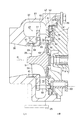
図3に示すように、本発明の実施形態に係る可変容量型過給機1は、エンジン(図示省略)からの排気ガスのエネルギーを利用して、エンジンに供給される空気を過給(圧縮)するものである。そして、可変容量型過給機1の具体的な構成等は、以下のようになる。
As shown in FIG. 3, the variable displacement supercharger 1 according to the embodiment of the present invention supercharges (compresses) the air supplied to the engine using the energy of the exhaust gas from the engine (not shown). ) The specific configuration of the
可変容量型過給機1は、ベアリングハウジング3を具備している。このベアリングハウジング3内には、ラジアルベアリング5及び一対のスラストベアリング7が設けられている。複数のベアリング5,7には、左右方向へ延びたロータ軸(タービン軸)9が回転可能に設けられている。換言すれば、ベアリングハウジング3には、ロータ軸9が複数のベアリング5,7を介して回転可能に設けられている。
The
ベアリングハウジング3の右側には、コンプレッサハウジング11が設けられている。このコンプレッサハウジング11内には、コンプレッサインペラ13がその軸心(換言すれば、ロータ軸9の軸心)C周りに回転可能に設けられている。また、コンプレッサインペラ13は、ロータ軸9の右端部に一体的に連結されたコンプレッサホイール15と、このコンプレッサホイール15の外周面に周方向に等間隔に設けられた複数のコンプレッサブレード17とを備えている。
A compressor housing 11 is provided on the right side of the bearing
コンプレッサハウジング11におけるコンプレッサインペラ13の入口側(コンプレッサハウジング11の右側部)には、空気を導入するための空気導入口19が形成されている。この空気導入口19は、空気を浄化するエアクリーナ(図示省略)に接続可能である。ベアリングハウジング3とコンプレッサハウジング11との間におけるコンプレッサインペラ13の出口側には、圧縮された空気を昇圧する環状のディフューザ流路21が形成されている。このディフューザ流路21は、空気導入口19に連通してある。更に、コンプレッサハウジング11の内部には、渦巻き状のコンプレッサスクロール流路23が形成されている。このコンプレッサスクロール流路23は、ディフューザ流路21に連通してある。そして、コンプレッサハウジング11の適宜位置には、圧縮された空気を排出するための空気排出口25が形成されている。この空気排出口25は、コンプレッサスクロール流路23に連通し、エンジンの吸気マニホールド(図示省略)に接続可能である。
An
図2及び図3に示すように、ベアリングハウジング3の左側には、タービンハウジング27が設けられている。このタービンハウジング27内には、排気ガスの圧力エネルギーを利用して回転力(回転トルク)を発生させるタービンインペラ29が軸心(タービンインペラ29の軸心、換言すれば、ロータ軸9の軸心)C周りに回転可能に設けられている。タービンインペラ29は、ロータ軸9の左端部に一体的に設けられたタービンホイール31と、このタービンホイール31の外周面に周方向に等間隔に設けられた複数のタービンブレード33とを備えている。
As shown in FIGS. 2 and 3, a
タービンハウジング27の適宜位置には、排気ガスを導入するためのガス導入口35が形成されている。このガス導入口35は、エンジンの排気マニホールド(図示省略)に接続可能である。タービンハウジング27の内部には、渦巻き状のタービンスクロール流路37が形成されている。このタービンスクロール流路37は、ガス導入口35に連通してある。そして、タービンハウジング27におけるタービンインペラ29の出口側(タービンハウジング27の左側部)には、排気ガスを排出するためのガス排出口39が形成されている。このガス排出口39は、タービンスクロール流路37に連通しており、排気ガスを浄化する排気ガス浄化装置(図示省略)に接続可能である。タービンハウジング27内におけるガス排出口39の入口側には、環状の段部41が形成されている。
A
なお、ベアリングハウジング3の左側面には、タービンインペラ29側からの熱を遮蔽する環状の遮熱板43が設けられている。ベアリングハウジング3の左側面と遮熱板43の外縁部との間には、波ワッシャ45が設けられている。波ワッシャ45は、遮熱板43を後述のノズルリング57に向けて付勢する。なお、波ワッシャ45は同じ機能を奏する皿バネや板バネ等の弾性部材でもよい。
An annular
タービンハウジング27内におけるタービンスクロール流路37とガス排出口39との間には、可変ノズルユニット47がタービンインペラ29を囲むように配設されている。可変ノズルユニット47は、タービンインペラ29側へ供給される排気ガスの流路面積(流量)を可変とするものである。そして、本発明の実施形態に係る可変ノズルユニット47の具体的な構成は、次のようになる。
A
図1(a)(b)及び図2に示すように、タービンハウジング27内には、サポートリング49がタービンインペラ29と同心状に配設されている。このサポートリング49は、タービンインペラ29と同心状に位置する環状の基部51を備えている。この基部51(サポートリング49の基部51)の外周縁には、筒状の中間部53が右方向(タービンインペラ29の軸方向一方側)へ突出して一体形成されている。サポートリング49の中間部53の先端縁には、環状の先端縁部(フランジ部)55が、サポートリング49の径方向外側へ突出して一体形成されている。この先端縁部55(サポートリング49のフランジ部55)は、ベアリングハウジング3とタービンハウジング27に挟持される。
As shown in FIGS. 1A and 1B and FIG. 2, a
図2に示すように、サポートリング49の基部51には、ノズルリング57が、基部51の円周方向に並んだ3つの連結ピン59の一端部(タービンインペラ29の軸方向一端部)のカシメ結合によって一体的に設けられている。ノズルリング57は、タービンインペラ29と同心状に位置している。遮熱板43の外周縁部は、波ワッシャ45の付勢力によってノズルリング57の内周縁部に圧接した状態で嵌合してある。また、ノズルリング57には、複数(1つのみ図示)の支持穴61が、ノズルリング57の円周方向に等間隔に貫通して形成されている。なお、本発明の実施形態にあっては、連結ピン59の個数は3つであるが、4つ以上であっても構わない。
As shown in FIG. 2, the
ノズルリング57に対して左右方向(タービンインペラ29の軸方向)に離隔対向した位置には、シュラウドリング63が複数の連結ピン59の他端部(タービンインペラ29の軸方向他端部)のカシメ結合によってノズルリング57と一体的に設けられている。シュラウドリング63は、タービンインペラ29と同心状に位置している。シュラウドリング63には、複数の支持穴65がシュラウドリング63の円周方向に等間隔に形成されている。複数の支持穴65は、ノズルリング57の複数の支持穴61に整合している。複数の連結ピン59は、ノズルリング57の対向面とシュラウドリング63の対向面との間隔を設定する機能を有している。
The
シュラウドリング63は、内周縁側に、複数のタービンブレード33の外縁を覆う筒状のシュラウド部67を有している。このシュラウド部67は、ガス排出口39側(下流側)へ突出し、タービンハウジング27の段部41の内側に位置している。また、シュラウドリング63のシュラウド部67の外周面には、リング溝(周溝)69が形成されている。更に、タービンハウジング27の段部41の内周面には、複数のシールリング71が自己の弾性力(複数のシールリング71の弾性力)によって圧接して設けられている。複数のシールリング71は、タービンスクロール流路37側からの排気ガスの漏れを抑える。各シールリング71の内周縁部は、シュラウドリング63のリング溝69に嵌入してある。
The
ノズルリング57の対向面とシュラウドリング63の対向面との間には、複数の可変ノズル73がノズルリング57(又はシュラウドリング63)の円周方向に等間隔に配設されている。各可変ノズル73は、タービンインペラ29の軸心Cに平行な軸心周りに正逆方向(開閉方向)へ回動可能である。また、各可変ノズル73の右側面(タービンインペラ29の軸方向一方側の側面)には、第1ノズル軸75が一体形成されている。各可変ノズル73の第1ノズル軸75は、ノズルリング57の対応する支持穴61に回動可能に支持されている。各可変ノズル73の左側面(タービンインペラ29の軸方向他方側の側面)には、第2ノズル軸77が第1ノズル軸75と同軸状に一体形成されている。各可変ノズル73の第2ノズル軸77は、シュラウドリング63の対応する支持穴65に回動可能に支持されている。なお、隣接した可変ノズル73の間隔は、個々の可変ノズル73の形状及び空力的な影響を考慮して、一定でなくてもよい。この場合、隣接した支持穴61の間隔、隣接した支持穴65の間隔も可変ノズル73の間隔に合わせて設定される。
Between the opposed surface of the
図2に示すように、ノズルリング57の対向面の反対側に形成した環状のリンク室79内には、複数の可変ノズル73を正逆方向(開閉方向)へ同期して回動させるためのリンク機構(同期機構)81が配設されている。このリンク機構81は、複数の可変ノズル73の第1ノズル軸75に連動連結してある。リンク機構81は、前述の特許文献1及び特許文献2等に示す公知の構成からなるものである。リンク機構81は、複数の可変ノズル73を開閉方向へ回動させるためのモータ又はシリンダ等の回動アクチュエータ(図示省略)に動力伝達機構83を介して接続されている。
As shown in FIG. 2, in the
続いて、本発明の実施形態に係る可変ノズルユニット47の構成の要部について説明する。
Next, the main part of the configuration of the
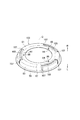
図1(a)(b)に示すように、サポートリング49は、前述のように、環状の基部51、筒状の中間部53、及び環状の先端縁部(フランジ部)55を備えている。また、サポートリング49の基部51は、3つ(連結ピン59と同数)のブリッジ状の結合エリアA1を円周方向に沿って有している。各結合エリアA1は、連結ピン59の一端部を挿通させるためのピン穴85を包囲している。各結合エリアA1は、ノズルリング57の対向面の反対面に接触している。
As shown in FIGS. 1A and 1B, the
サポートリング49の径方向において各結合エリアA1の外側に位置するサポートリング49の一部分には、第1切欠87が形成されている。具体的には、第1切欠87は、基部51から中間部53に亘って形成されている。第1切欠87は、ノズルリング57の円周の接線方向へ延びている。サポートリング49の径方向における各結合エリアA1の外側であって、サポートリング49の円周方向に隣接する第1切欠87、87の間には、第2切欠89又は第2切欠91が基部51から中間部53に亘って形成されている。第1切欠87及び第2切欠89,91は、結合エリアA1に対するサポートリング49の中間部53の変形(変位)を許容できるように構成されている。
A
なお、第1切欠87、第2切欠89,91の各幅(延伸方向に直交する方向における幅)は、サポートリング49の本来の機能及び機械的強度、並びに各切欠の上記の機能を損なわない限り任意である。即ち、各幅は延伸方向における何れの箇所において一定でもよく、例えば隣接する部材の形状に合わせて、変化してもよい。また、これらの幅は互いに異なる値であってもよい。例えば図1(a)に示す例では、結合エリアA1の位置関係により、第2切欠89の幅が、第1切欠87及び第2切欠91の各幅よりも大きく設定されている。
In addition, each width | variety (width in the direction orthogonal to an extending | stretching direction) of the
続いて、本発明の実施形態の作用及び効果について説明する。 Then, the effect | action and effect of embodiment of this invention are demonstrated.
ガス導入口35から導入した排気ガスがタービンスクロール流路37を経由してタービンインペラ29の入口側から出口側へ流通する。すると、排気ガスの圧力エネルギーを利用して回転力(回転トルク)を発生させて、ロータ軸9及びコンプレッサインペラ13をタービンインペラ29と一体的に回転させることができる。これにより、空気導入口19から導入した空気を圧縮して、ディフューザ流路21及びコンプレッサスクロール流路23を経由して空気排出口25から排出する。そして、エンジンに供給される空気を過給(圧縮)する。
Exhaust gas introduced from the
可変容量型過給機1の運転中、エンジン回転数が高回転域にあって、排気ガスの流量が多い場合には、回動アクチュエータによってリンク機構81を作動させつつ、複数の可変ノズル73を正方向(開方向)へ同期して回動させる。これにより、タービンインペラ29側へ供給される排気ガスのガス流路面積(可変ノズル73のスロート面積)を大きくして、多くの排気ガスを供給する。一方、エンジン回転数が低回転域にあって、排気ガスの流量が少ない場合には、回動アクチュエータによってリンク機構81を作動させつつ、複数の可変ノズル73を逆方向(閉方向)へ同期して回動させる。これにより、タービンインペラ29側へ供給される排気ガスのガス流路面積を小さくして、排気ガスの流速を高めて、タービンインペラ29の仕事量を十分に確保する。よって、排気ガスの流量の多少に関係なく、タービンインペラ29によって回転力を十分かつ安定的に発生させることができる(可変容量型過給機1の通常の作用)。
During operation of the
前述のように、サポートリング49の基部51がピン穴85を包囲する複数の結合エリアA1をサポートリング49の円周方向に沿って有し、サポートリング49における各結合エリアA1の周辺に前述のように第1切欠87、第2切欠89、及び第2切欠91が形成されている。そのため、可変容量型過給機1の運転中に、サポートリング49の中間部53が内側から押し広がるように熱変形しても、それに追従してノズルリング57が変形することを抑えることができる。これにより、ノズルサイドクリアランスを大きめに設定しなくても、可変容量型過給機1の運転中におけるノズルリング57の対向面とシュラウドリング63の対向面の平行度を十分に確保することができる。換言すれば、可変容量型過給機1の運転中におけるノズルリング57の対向面とシュラウドリング63の対向面の平行度を十分に確保しつつ、ノズルサイドクリアランスを極力小さくすることができる。
As described above, the
また、第1切欠87及び第2切欠91の各開口面積は小さい。従って、サポートリング49は、リンク機構81の遮熱板としての機能を維持することができる。
Moreover, each opening area of the
従って、本発明の実施形態によれば、複数の可変ノズル73の渋りを抑えて、複数の可変ノズル73の回動動作の安定性を十分に確保した上で、ノズルサイドクリアランスからの漏れ流れを低減して、可変容量型過給機1のタービン効率を向上させることができる。
Therefore, according to the embodiment of the present invention, the flow of leakage from the nozzle side clearance can be prevented while suppressing the astringency of the plurality of
また、前述のように、第1切欠87及び第2切欠91の開口面積を小さくして、サポートリング49がリンク機構81の遮熱板としての機能を維持できる。そのため、リンク機構81の熱変形を抑えて、可変ノズルユニット47の耐久性、換言すれば、可変容量型過給機1の耐久性を十分に確保することができる。
Further, as described above, the opening area of the
(変形例1)
本発明の実施形態の変形例1として、可変ノズルユニット47の構成要素としてサポートリング49に代えて、図4(a)に示すようなサポートリング93を用いても構わない。
(Modification 1)
As a first modification of the embodiment of the present invention, a
具体的には、サポートリング93は、サポートリング49と同様に、環状の基部51、筒状の中間部53、及び環状の先端縁部(フランジ部)55を備えている。サポートリング93の基部51は、3つの結合エリアA2をサポートリング93(基部51)の円周方向に沿って有している。3つの結合エリアA2は、ピン穴85を包囲し、ノズルリング57の対向面の反対面に接触している。サポートリング93の中間部53には、切欠95がサポートリング93(中間部53)の円周方向に沿って形成されている。切欠95は、サポートリング93の径方向における各結合エリアA2の外側に位置する。そして、切欠95は、結合エリアA2に対するサポートリング93の中間部53の変形を許容できるように構成されている。
Specifically, like the
なお、可変ノズルユニット47の構成要素としてサポートリング93を用いた場合にも、本発明の実施形態と同様の作用及び効果を奏するものである。
Even when the
(変形例2)
本発明の実施形態の変形例2として、可変ノズルユニット47の構成要素としてサポートリング49に代えて、図4(b)に示すようなサポートリング97を用いても構わない。
(Modification 2)
As a second modification of the embodiment of the present invention, a
具体的には、サポートリング97は、サポートリング49と同様に、環状の基部51、筒状の中間部53、及び環状の先端縁部(フランジ部)55を備えている。サポートリング97の基部51は、3つの結合エリアA3をサポートリング97(基部51)の円周方向に沿って有している。3つの結合エリアA3は、ピン穴85を包囲し、ノズルリング57の対向面の反対面に接触している。サポートリング97の中間部53には、第1切欠99がサポートリング97(中間部53)の円周方向に沿って形成されている。サポートリング97の径方向における各結合エリアA3の外側には、2つの第2切欠101、101が第1切欠99の両端部から基部51に亘ってそれぞれ形成されている。そして、各第1切欠99及び第2切欠101は、結合エリアA3に対するサポートリング97の中間部53の変形を許容できるように構成されている。第1切欠99及び第2切欠101の各幅は、第1切欠87、第2切欠89,91と同様に、第1切欠87、第2切欠89,91に求められる条件に従う限り、任意である。
Specifically, like the
なお、可変ノズルユニット47の構成要素としてサポートリング97を用いた場合にも、本発明の実施形態と同様の作用及び効果を奏するものである。
Even when the
(変形例3)
本発明の実施形態の変形例3として、可変ノズルユニット47の構成要素としてサポートリング49に代えて、図5に示すようなサポートリング103を用いても構わない。
(Modification 3)
As a third modification of the embodiment of the present invention, a
具体的には、サポートリング103は、サポートリング49と同様に、環状の基部51、筒状の中間部53、及び環状の先端縁部(フランジ部)55を備えている。サポートリング103の基部51は、3つの結合エリアA4をサポートリング103(基部51)の円周方向に沿って有している。3つの結合エリアA4は、ピン穴85を包囲し、ノズルリング57の対向面の反対面に接触している。サポートリング103の径方向において各結合エリアA4の外側に位置する基部51の一部分には、第1切欠105がサポートリング103(基部51)の円周方向に沿って形成されている。サポートリング103の径方向において各結合エリアA4の外側に位置するサポートリング103の一部分には、2つの第2切欠107が第1切欠105の両端部から中間部53に亘ってそれぞれ形成されている。第1切欠105及び第2切欠107は、結合エリアA4に対するサポートリング103の中間部53の変形を許容できるように構成されている。第1切欠105及び第2切欠107の各幅は、第1切欠87、第2切欠89,91と同様に、第1切欠87、第2切欠89,91に求められる条件に従う限り、任意である。
Specifically, like the
なお、可変ノズルユニット47の構成要素として別のサポートリング103を用いた場合にも、本発明の実施形態と同様の作用及び効果を奏するものである。
Even when another
本発明は、前述の実施形態の説明に限られるものではなく、種々の態様で実施可能である。また、本発明に包含される権利範囲は、これらの実施形態に限定されないものである。 The present invention is not limited to the description of the above-described embodiment, and can be implemented in various aspects. Further, the scope of rights encompassed by the present invention is not limited to these embodiments.
1:可変容量型過給機、3:ベアリングハウジング、9:ロータ軸、11: コンプレッサハウジング、13:コンプレッサインペラ、27:タービンハウジング、29:タービンインペラ、33:タービンブレード、39:ガス排出口、47:可変ノズルユニット、49:サポートリング、51:基部、53:中間部、55:先端縁部、57:ノズルリング、59:連結ピン、61:支持穴、63:シュラウドリング、65:支持穴、67:シュラウド部、73:可変ノズル、75:第1ノズル軸、77:第2ノズル軸、79:リンク室、81:リンク機構、85:ピン穴、A1:結合エリア、87:第1切欠、89:第2切欠、91:第2切欠、93:サポートリング、A2:結合エリア、95:切欠、97:サポートリング、A3:結合エリア、99:第1切欠、101:第2切欠、103:サポートリング、A2:結合エリア、105:第1切欠、107:第2切欠 1: variable displacement supercharger, 3: bearing housing, 9: rotor shaft, 11: compressor housing, 13: compressor impeller, 27: turbine housing, 29: turbine impeller, 33: turbine blade, 39: gas outlet, 47: variable nozzle unit, 49: support ring, 51: base, 53: intermediate part, 55: tip edge, 57: nozzle ring, 59: connecting pin, 61: support hole, 63: shroud ring, 65: support hole 67: shroud portion, 73: variable nozzle, 75: first nozzle shaft, 77: second nozzle shaft, 79: link chamber, 81: link mechanism, 85: pin hole, A1: coupling area, 87: first notch 89: second notch, 91: second notch, 93: support ring, A2: coupling area, 95: notch, 97: support ring, A3: connection Area, 99: first cutout, 101: second cutout, 103: support ring, A2: bond area, 105: first notch, 107: second notch
Claims (6)
前記タービンハウジング内に配設されるサポートリングであって、環状の基部、前記基部の外周縁に前記タービンインペラの軸方向一方側へ突出して一体形成された筒状の中間部、及び前記中間部の先端縁に、前記サポートリングの径方向外側へ突出して一体形成されかつ前記可変容量型過給機におけるベアリングハウジングと前記タービンハウジングに挟持される環状の先端縁部を備えたサポートリングと、
前記サポートリングの前記基部に、前記基部の円周方向に並んだ3つ以上の連結ピンの一端部の結合によって一体的に設けられたノズルリングと、
前記ノズルリングに対して前記軸方向に離隔した位置に、複数の前記連結ピンの他端部の結合によって前記ノズルリングと一体的に設けられ、前記タービンインペラにおける複数のタービンブレードの先端縁を覆うシュラウドリングと、
前記ノズルリングの対向面と前記シュラウドリングの対向面との間に、前記ノズルリング又は前記シュラウドリングの円周方向に配設され、前記タービンインペラの軸心に平行な軸心回りに正逆方向へ回動可能な複数の可変ノズルと、を具備し、
前記サポートリングの前記基部は、前記連結ピンの一端部を挿通させるためのピン穴を包囲しかつ前記ノズルリングの対向面の反対面に接触する前記連結ピンと同数の結合エリアを前記サポートリングの円周方向に沿って有し、前記サポートリングの径方向における各結合エリアの外側に位置する前記サポートリングの一部分には切欠が形成されていることを特徴とする可変ノズルユニット。 A variable nozzle unit that is disposed so as to surround a turbine impeller in a turbine housing of a variable displacement turbocharger, and that can change a flow passage area of exhaust gas supplied to the turbine impeller,
A support ring disposed in the turbine housing, the annular base portion, a cylindrical intermediate portion integrally formed on the outer peripheral edge of the base portion so as to protrude toward one axial direction of the turbine impeller, and the intermediate portion A support ring having an annular tip edge portion which is integrally formed to project radially outward of the support ring and is sandwiched between the bearing housing and the turbine housing in the variable displacement supercharger.
A nozzle ring provided integrally with the base of the support ring by coupling one end of three or more connecting pins arranged in the circumferential direction of the base;
The nozzle ring is provided integrally with the nozzle ring at a position spaced apart from the nozzle ring in the axial direction, and covers the tip edges of the turbine blades in the turbine impeller. With shroud rings,
Between the facing surface of the nozzle ring and the facing surface of the shroud ring, the nozzle ring or the shroud ring is disposed in the circumferential direction, and forward and reverse directions about an axis parallel to the axis of the turbine impeller A plurality of variable nozzles capable of rotating to,
The base of the support ring surrounds a pin hole for inserting one end of the connection pin, and has the same number of connection areas as the connection pin that contacts the opposite surface of the opposite surface of the nozzle ring. A variable nozzle unit having a notch formed in a part of the support ring that is provided along a circumferential direction and is located outside each coupling area in a radial direction of the support ring.
請求項1から請求項5のうちのいずれか一項に記載の可変ノズルユニットを具備したことを特徴とする可変容量型過給機。 In the variable capacity supercharger that uses the energy of the exhaust gas from the engine to supercharge the air supplied to the engine side,
A variable displacement supercharger comprising the variable nozzle unit according to any one of claims 1 to 5.
Priority Applications (6)
| Application Number | Priority Date | Filing Date | Title |
|---|---|---|---|
| JP2013261988A JP6152049B2 (en) | 2013-12-19 | 2013-12-19 | Variable nozzle unit and variable capacity turbocharger |
| CN201480066448.1A CN105814293B (en) | 2013-12-19 | 2014-10-23 | Variable-nozzle unit and variable capacity type booster |
| PCT/JP2014/078161 WO2015093143A1 (en) | 2013-12-19 | 2014-10-23 | Variable nozzle unit and variable-capacity supercharger |
| DE112014005943.9T DE112014005943T5 (en) | 2013-12-19 | 2014-10-23 | Variable nozzle unit and turbocharger with variable geometry system |
| EP14871084.1A EP3085919A4 (en) | 2013-12-19 | 2014-10-23 | Variable nozzle unit and variable geometry turbocharger |
| US15/174,186 US10233828B2 (en) | 2013-12-19 | 2016-06-06 | Variable nozzle unit and variable geometry system turbocharger |
Applications Claiming Priority (1)
| Application Number | Priority Date | Filing Date | Title |
|---|---|---|---|
| JP2013261988A JP6152049B2 (en) | 2013-12-19 | 2013-12-19 | Variable nozzle unit and variable capacity turbocharger |
Publications (2)
| Publication Number | Publication Date |
|---|---|
| JP2015117645A true JP2015117645A (en) | 2015-06-25 |
| JP6152049B2 JP6152049B2 (en) | 2017-06-21 |
Family
ID=53402500
Family Applications (1)
| Application Number | Title | Priority Date | Filing Date |
|---|---|---|---|
| JP2013261988A Expired - Fee Related JP6152049B2 (en) | 2013-12-19 | 2013-12-19 | Variable nozzle unit and variable capacity turbocharger |
Country Status (6)
| Country | Link |
|---|---|
| US (1) | US10233828B2 (en) |
| EP (1) | EP3085919A4 (en) |
| JP (1) | JP6152049B2 (en) |
| CN (1) | CN105814293B (en) |
| DE (1) | DE112014005943T5 (en) |
| WO (1) | WO2015093143A1 (en) |
Cited By (1)
| Publication number | Priority date | Publication date | Assignee | Title |
|---|---|---|---|---|
| WO2019187474A1 (en) * | 2018-03-29 | 2019-10-03 | 株式会社Ihi | Supercharger |
Families Citing this family (4)
| Publication number | Priority date | Publication date | Assignee | Title |
|---|---|---|---|---|
| JP6331736B2 (en) | 2014-06-13 | 2018-05-30 | 株式会社Ihi | Variable nozzle unit and variable capacity turbocharger |
| DE102016125189B4 (en) * | 2016-12-21 | 2020-11-26 | Man Energy Solutions Se | turbocharger |
| DE102017121316A1 (en) * | 2017-09-14 | 2019-03-14 | Man Diesel & Turbo Se | turbocharger |
| DE102018216408A1 (en) * | 2018-09-26 | 2020-03-26 | Continental Automotive Gmbh | Exhaust gas guide device for an exhaust gas turbocharger, exhaust gas turbocharger and method for producing the exhaust gas guide device |
Citations (7)
| Publication number | Priority date | Publication date | Assignee | Title |
|---|---|---|---|---|
| JP2008106667A (en) * | 2006-10-25 | 2008-05-08 | Aisin Takaoka Ltd | Turbine housing |
| JP2010196657A (en) * | 2009-02-26 | 2010-09-09 | Mitsubishi Heavy Ind Ltd | Variable displacement exhaust turbo-charger |
| JP2010216281A (en) * | 2009-03-13 | 2010-09-30 | Akita Fine Blanking:Kk | Exhaust guide assembly in vgs type turbocharger |
| EP2325454A1 (en) * | 2008-08-12 | 2011-05-25 | Keyyang Precision Co., Ltd. | Turbocharger equipped with a variable nozzle device |
| EP2594745A2 (en) * | 2011-09-30 | 2013-05-22 | Honeywell International Inc. | Turbocharger variable-nozzle assembly with vane sealing arrangement |
| JP2013253519A (en) * | 2012-06-06 | 2013-12-19 | Ihi Corp | Variable nozzle unit and variable capacity type supercharger |
| JP2013253520A (en) * | 2012-06-06 | 2013-12-19 | Ihi Corp | Variable nozzle unit and variable capacity type supercharger |
Family Cites Families (13)
| Publication number | Priority date | Publication date | Assignee | Title |
|---|---|---|---|---|
| JPH0737519A (en) | 1993-07-19 | 1995-02-07 | Sony Corp | Electron gun |
| JP2006012588A (en) | 2004-06-25 | 2006-01-12 | Shiizu:Kk | Optical component, and illumination light using the same |
| EP1816317B1 (en) * | 2006-02-02 | 2013-06-12 | IHI Corporation | Turbocharger with variable nozzle |
| JP4307500B2 (en) | 2007-09-21 | 2009-08-05 | 株式会社豊田自動織機 | Turbocharger with variable nozzle mechanism |
| JP2009144546A (en) * | 2007-12-12 | 2009-07-02 | Ihi Corp | Turbocharger |
| JP5141335B2 (en) | 2008-03-28 | 2013-02-13 | 株式会社Ihi | Variable nozzle unit and variable displacement turbocharger |
| JP2009243431A (en) | 2008-03-31 | 2009-10-22 | Ihi Corp | Variable nozzle unit and variable capacity type turbocharger |
| JP5071283B2 (en) | 2008-07-17 | 2012-11-14 | 株式会社Ihi | Turbocharger |
| JP5136496B2 (en) | 2009-03-27 | 2013-02-06 | 株式会社Ihi | Variable nozzle mechanism and variable displacement turbocharger |
| JP5397144B2 (en) | 2009-10-14 | 2014-01-22 | 株式会社Ihi | Assembly method of variable nozzle unit |
| JP5421057B2 (en) | 2009-10-19 | 2014-02-19 | トヨタ自動車株式会社 | Turbocharger |
| CN102639838B (en) * | 2009-12-17 | 2015-08-05 | 株式会社Ihi | Turbosupercharger |
| JP5949164B2 (en) * | 2012-05-29 | 2016-07-06 | 株式会社Ihi | Variable nozzle unit and variable capacity turbocharger |
-
2013
- 2013-12-19 JP JP2013261988A patent/JP6152049B2/en not_active Expired - Fee Related
-
2014
- 2014-10-23 CN CN201480066448.1A patent/CN105814293B/en not_active Expired - Fee Related
- 2014-10-23 WO PCT/JP2014/078161 patent/WO2015093143A1/en active Application Filing
- 2014-10-23 EP EP14871084.1A patent/EP3085919A4/en not_active Withdrawn
- 2014-10-23 DE DE112014005943.9T patent/DE112014005943T5/en not_active Withdrawn
-
2016
- 2016-06-06 US US15/174,186 patent/US10233828B2/en not_active Expired - Fee Related
Patent Citations (7)
| Publication number | Priority date | Publication date | Assignee | Title |
|---|---|---|---|---|
| JP2008106667A (en) * | 2006-10-25 | 2008-05-08 | Aisin Takaoka Ltd | Turbine housing |
| EP2325454A1 (en) * | 2008-08-12 | 2011-05-25 | Keyyang Precision Co., Ltd. | Turbocharger equipped with a variable nozzle device |
| JP2010196657A (en) * | 2009-02-26 | 2010-09-09 | Mitsubishi Heavy Ind Ltd | Variable displacement exhaust turbo-charger |
| JP2010216281A (en) * | 2009-03-13 | 2010-09-30 | Akita Fine Blanking:Kk | Exhaust guide assembly in vgs type turbocharger |
| EP2594745A2 (en) * | 2011-09-30 | 2013-05-22 | Honeywell International Inc. | Turbocharger variable-nozzle assembly with vane sealing arrangement |
| JP2013253519A (en) * | 2012-06-06 | 2013-12-19 | Ihi Corp | Variable nozzle unit and variable capacity type supercharger |
| JP2013253520A (en) * | 2012-06-06 | 2013-12-19 | Ihi Corp | Variable nozzle unit and variable capacity type supercharger |
Cited By (5)
| Publication number | Priority date | Publication date | Assignee | Title |
|---|---|---|---|---|
| WO2019187474A1 (en) * | 2018-03-29 | 2019-10-03 | 株式会社Ihi | Supercharger |
| CN111699307A (en) * | 2018-03-29 | 2020-09-22 | 株式会社Ihi | Pressure booster |
| JPWO2019187474A1 (en) * | 2018-03-29 | 2021-01-14 | 株式会社Ihi | Supercharger |
| US11162381B2 (en) | 2018-03-29 | 2021-11-02 | Ihi Corporation | Turbocharger |
| CN111699307B (en) * | 2018-03-29 | 2022-05-10 | 株式会社Ihi | Pressure booster |
Also Published As
| Publication number | Publication date |
|---|---|
| CN105814293A (en) | 2016-07-27 |
| US20160281593A1 (en) | 2016-09-29 |
| US10233828B2 (en) | 2019-03-19 |
| CN105814293B (en) | 2018-12-11 |
| EP3085919A4 (en) | 2017-09-06 |
| DE112014005943T5 (en) | 2016-09-29 |
| EP3085919A1 (en) | 2016-10-26 |
| WO2015093143A1 (en) | 2015-06-25 |
| JP6152049B2 (en) | 2017-06-21 |
Similar Documents
| Publication | Publication Date | Title |
|---|---|---|
| JP5949164B2 (en) | Variable nozzle unit and variable capacity turbocharger | |
| JP6331736B2 (en) | Variable nozzle unit and variable capacity turbocharger | |
| JP6542246B2 (en) | Variable displacement turbocharger | |
| US9664060B2 (en) | Variable nozzle unit and variable geometry system turbocharger | |
| JP5710452B2 (en) | Turbocharger | |
| JP6163789B2 (en) | Variable nozzle unit and variable capacity turbocharger | |
| JP6098233B2 (en) | Variable capacity turbocharger | |
| JP6152049B2 (en) | Variable nozzle unit and variable capacity turbocharger | |
| WO2016039015A1 (en) | Variable nozzle unit and variable displacement supercharger | |
| WO2015114965A1 (en) | Variable displacement supercharger | |
| WO2015114971A1 (en) | Variable nozzle unit and variable displacement supercharger | |
| JP2016017408A (en) | Variable nozzle unit and variable displacement turbocharger | |
| JP2014218943A (en) | Variable nozzle unit and variable displacement supercharger | |
| JP2013245655A (en) | Variable nozzle unit and variable displacement type supercharger | |
| JP5440390B2 (en) | Seal structure and variable capacity turbocharger | |
| JP2013253521A (en) | Variable nozzle unit and variable capacity type supercharger | |
| JP2013253519A (en) | Variable nozzle unit and variable capacity type supercharger | |
| JP2013194546A (en) | Variable nozzle unit and variable capacity type supercharger | |
| JP2015031237A (en) | Variable nozzle unit and variable displacement type supercharger | |
| JP5915394B2 (en) | Variable nozzle unit and variable capacity turbocharger | |
| JP6146507B2 (en) | Variable nozzle unit and variable capacity turbocharger | |
| JP6089791B2 (en) | Variable nozzle unit and variable capacity turbocharger | |
| JP6638594B2 (en) | Supercharger | |
| JP6149426B2 (en) | Variable capacity turbocharger |
Legal Events
| Date | Code | Title | Description |
|---|---|---|---|
| A621 | Written request for application examination |
Free format text: JAPANESE INTERMEDIATE CODE: A621 Effective date: 20160616 |
|
| TRDD | Decision of grant or rejection written | ||
| A01 | Written decision to grant a patent or to grant a registration (utility model) |
Free format text: JAPANESE INTERMEDIATE CODE: A01 Effective date: 20170509 |
|
| A61 | First payment of annual fees (during grant procedure) |
Free format text: JAPANESE INTERMEDIATE CODE: A61 Effective date: 20170526 |
|
| R150 | Certificate of patent or registration of utility model |
Ref document number: 6152049 Country of ref document: JP Free format text: JAPANESE INTERMEDIATE CODE: R150 |
|
| R250 | Receipt of annual fees |
Free format text: JAPANESE INTERMEDIATE CODE: R250 |
|
| LAPS | Cancellation because of no payment of annual fees |