JP6542246B2 - Variable displacement turbocharger - Google Patents
Variable displacement turbocharger Download PDFInfo
- Publication number
- JP6542246B2 JP6542246B2 JP2016551928A JP2016551928A JP6542246B2 JP 6542246 B2 JP6542246 B2 JP 6542246B2 JP 2016551928 A JP2016551928 A JP 2016551928A JP 2016551928 A JP2016551928 A JP 2016551928A JP 6542246 B2 JP6542246 B2 JP 6542246B2
- Authority
- JP
- Japan
- Prior art keywords
- nozzle
- nozzle ring
- turbine
- variable
- ring
- Prior art date
- Legal status (The legal status is an assumption and is not a legal conclusion. Google has not performed a legal analysis and makes no representation as to the accuracy of the status listed.)
- Active
Links
Images


Classifications
-
- F—MECHANICAL ENGINEERING; LIGHTING; HEATING; WEAPONS; BLASTING
- F02—COMBUSTION ENGINES; HOT-GAS OR COMBUSTION-PRODUCT ENGINE PLANTS
- F02B—INTERNAL-COMBUSTION PISTON ENGINES; COMBUSTION ENGINES IN GENERAL
- F02B37/00—Engines characterised by provision of pumps driven at least for part of the time by exhaust
- F02B37/12—Control of the pumps
- F02B37/24—Control of the pumps by using pumps or turbines with adjustable guide vanes
-
- F—MECHANICAL ENGINEERING; LIGHTING; HEATING; WEAPONS; BLASTING
- F01—MACHINES OR ENGINES IN GENERAL; ENGINE PLANTS IN GENERAL; STEAM ENGINES
- F01D—NON-POSITIVE DISPLACEMENT MACHINES OR ENGINES, e.g. STEAM TURBINES
- F01D11/00—Preventing or minimising internal leakage of working-fluid, e.g. between stages
- F01D11/003—Preventing or minimising internal leakage of working-fluid, e.g. between stages by packing rings; Mechanical seals
-
- F—MECHANICAL ENGINEERING; LIGHTING; HEATING; WEAPONS; BLASTING
- F01—MACHINES OR ENGINES IN GENERAL; ENGINE PLANTS IN GENERAL; STEAM ENGINES
- F01D—NON-POSITIVE DISPLACEMENT MACHINES OR ENGINES, e.g. STEAM TURBINES
- F01D17/00—Regulating or controlling by varying flow
- F01D17/10—Final actuators
- F01D17/12—Final actuators arranged in stator parts
- F01D17/14—Final actuators arranged in stator parts varying effective cross-sectional area of nozzles or guide conduits
- F01D17/16—Final actuators arranged in stator parts varying effective cross-sectional area of nozzles or guide conduits by means of nozzle vanes
- F01D17/165—Final actuators arranged in stator parts varying effective cross-sectional area of nozzles or guide conduits by means of nozzle vanes for radial flow, i.e. the vanes turning around axes which are essentially parallel to the rotor centre line
-
- F—MECHANICAL ENGINEERING; LIGHTING; HEATING; WEAPONS; BLASTING
- F02—COMBUSTION ENGINES; HOT-GAS OR COMBUSTION-PRODUCT ENGINE PLANTS
- F02B—INTERNAL-COMBUSTION PISTON ENGINES; COMBUSTION ENGINES IN GENERAL
- F02B39/00—Component parts, details, or accessories relating to, driven charging or scavenging pumps, not provided for in groups F02B33/00 - F02B37/00
-
- F—MECHANICAL ENGINEERING; LIGHTING; HEATING; WEAPONS; BLASTING
- F05—INDEXING SCHEMES RELATING TO ENGINES OR PUMPS IN VARIOUS SUBCLASSES OF CLASSES F01-F04
- F05D—INDEXING SCHEME FOR ASPECTS RELATING TO NON-POSITIVE-DISPLACEMENT MACHINES OR ENGINES, GAS-TURBINES OR JET-PROPULSION PLANTS
- F05D2220/00—Application
- F05D2220/40—Application in turbochargers
-
- Y—GENERAL TAGGING OF NEW TECHNOLOGICAL DEVELOPMENTS; GENERAL TAGGING OF CROSS-SECTIONAL TECHNOLOGIES SPANNING OVER SEVERAL SECTIONS OF THE IPC; TECHNICAL SUBJECTS COVERED BY FORMER USPC CROSS-REFERENCE ART COLLECTIONS [XRACs] AND DIGESTS
- Y02—TECHNOLOGIES OR APPLICATIONS FOR MITIGATION OR ADAPTATION AGAINST CLIMATE CHANGE
- Y02T—CLIMATE CHANGE MITIGATION TECHNOLOGIES RELATED TO TRANSPORTATION
- Y02T10/00—Road transport of goods or passengers
- Y02T10/10—Internal combustion engine [ICE] based vehicles
- Y02T10/12—Improving ICE efficiencies
Description
本開示は、可変ノズルユニット及び可変容量型過給機に関する。 The present disclosure relates to a variable nozzle unit and a variable displacement turbocharger.
可変容量型過給機では、タービンハウジング内のタービンスクロール流路とタービン翼車(タービンインペラ)との間に、可変ノズルユニットが設けられる。可変ノズルユニットは、タービンハウジング内のタービン翼車の外周側に設けられている。可変ノズルユニットは、一般的には、タービン翼車の軸方向に沿って互いに離間して設けられた第1ノズルリング及び第2ノズルリングと、第1ノズルリング及び第2ノズルリングに挟まれ円周方向に沿って等間隔に複数配置された可変ノズルと、を備えている。第1ノズルリングは、タービン翼車の軸方向に沿ってタービン翼車よりも軸受ハウジング側に設けられる。第2ノズルリングは、タービン翼車の外周を囲むように配置される。また、複数の可変ノズルは、それぞれタービン翼車の軸方向に沿って延びるノズル軸を有し、第1ノズルリング及び第2ノズルリングによってノズル軸が回動可能に支持される。上記の構成を備える可変ノズルユニットでは、複数の可変ノズルを開く方向へ同期して回転させることで、タービン翼車側へ供給される排気ガスの流路面積を大きくすることができる。また、複数の可変ノズルを絞る方向へ同期して回転させることで、排気ガスの流路面積を小さくすることができる。このように、可変容量型過給機では、可変ノズルによって流路面積を変化させて過給圧を制御することで、過給効率を好適に維持することができる。 In the variable displacement supercharger, a variable nozzle unit is provided between a turbine scroll passage in a turbine housing and a turbine impeller. The variable nozzle unit is provided on the outer peripheral side of the turbine wheel in the turbine housing. Generally, the variable nozzle unit has a first nozzle ring and a second nozzle ring provided apart from each other along the axial direction of the turbine wheel, and a circle sandwiched by the first nozzle ring and the second nozzle ring. And a plurality of variable nozzles arranged at equal intervals along the circumferential direction. The first nozzle ring is provided on the bearing housing side of the turbine wheel along the axial direction of the turbine wheel. The second nozzle ring is disposed to surround the outer periphery of the turbine wheel. Each of the plurality of variable nozzles has a nozzle axis extending along the axial direction of the turbine wheel, and the nozzle axis is rotatably supported by the first nozzle ring and the second nozzle ring. In the variable nozzle unit having the above configuration, the flow passage area of the exhaust gas supplied to the turbine wheel side can be increased by synchronously rotating the plurality of variable nozzles in the opening direction. In addition, the flow passage area of the exhaust gas can be reduced by synchronously rotating the plurality of variable nozzles in the narrowing direction. As described above, in the variable displacement supercharger, the supercharging efficiency can be suitably maintained by changing the flow passage area with the variable nozzle to control the supercharging pressure.
このような可変容量型過給機では、過給効率の向上を目的として、排気ガスの漏れ(リーク)を防ぐための構成が種々検討されている。例えば、特許文献1では、第2ノズルリングのうち、第1ノズルリングとの対向面とは逆の背面側にシールカバーを設けることで、タービンスクロール流路からタービン翼車の出口側への排気ガスの漏れを防止する構成が示されている。 In such variable displacement turbochargers, various configurations for preventing leakage of exhaust gas have been studied for the purpose of improving the supercharging efficiency. For example, in Patent Document 1, the exhaust from the turbine scroll flow path to the outlet side of the turbine wheel is provided by providing a seal cover on the back side opposite to the surface facing the first nozzle ring in the second nozzle ring. An arrangement for preventing gas leaks is shown.
近年、低燃費、低環境負荷に対応したディーゼルエンジンの開発が進められていて、このようなディーゼルエンジンに適用可能な可変容量型過給機に関しても、小型高出力化が求められている。 In recent years, development of a diesel engine compatible with low fuel consumption and low environmental load has been promoted, and a reduction in size and an increase in output are also required for a variable displacement turbocharger applicable to such a diesel engine.
本開示は、過給効率の更なる向上が図られた可変ノズルユニット及び可変容量型過給機を説明する。 The present disclosure describes a variable nozzle unit and a variable displacement turbocharger in which further improvement of the supercharging efficiency is achieved.
上記目的を達成するため、本開示の一形態に係る可変ノズルユニットは、可変容量型過給機におけるタービンハウジング内のタービンスクロール流路とタービン翼車との間に配置されて、タービンスクロール流路からタービン翼車へ供給される排気ガスの流路面積を変更する可変ノズルユニットであって、タービンハウジング内に配置され、第1支持孔が複数形成された第1ノズルリングと、第1ノズルリングに対してタービン翼車の軸線方向に沿って離間した位置に対向配置され、第1支持孔に対応した貫通孔である第2支持孔が複数形成された第2ノズルリングと、第1ノズルリングと第2ノズルリングとによって回動可能に支持される複数の可変ノズルと、第2ノズルリングにおけるタービンハウジングと対向する面に沿ってタービンスクロール流路とタービン翼車との間に配置された複数のシール部材と、を備え、可変ノズルは、一方側に延びる第1ノズル軸が第1支持孔に回動可能に支持されると共に、他方側に延びる第2ノズル軸が第2支持孔に回動可能に支持され、複数のシール部材に含まれる第1シール部材は、第2支持孔よりもタービン翼車側に設けられることを特徴とする。 In order to achieve the above object, a variable nozzle unit according to an embodiment of the present disclosure is disposed between a turbine scroll passage and a turbine wheel in a turbine housing of a variable displacement turbocharger, Nozzle unit for changing the flow passage area of exhaust gas supplied from the engine to the turbine wheel, the first nozzle ring disposed in the turbine housing and having a plurality of first support holes, and a first nozzle ring A second nozzle ring oppositely disposed at a position separated along the axial direction of the turbine wheel, and in which a plurality of second support holes corresponding to the first support holes are formed, and a first nozzle ring And a plurality of variable nozzles rotatably supported by the second nozzle ring and a turbine along a surface of the second nozzle ring facing the turbine housing A plurality of seal members disposed between the crawl passage and the turbine wheel, wherein the variable nozzle has a first nozzle shaft extending to one side rotatably supported in the first support hole, A second nozzle shaft extending to the other side is rotatably supported in the second support hole, and the first seal member included in the plurality of seal members is provided closer to the turbine wheel than the second support hole. I assume.
本開示によれば、過給効率の更なる向上が図られた可変ノズルユニット及び可変容量型過給機が提供される。 According to the present disclosure, a variable nozzle unit and a variable displacement supercharger are provided in which the supercharging efficiency is further improved.
本開示の一形態に係る可変ノズルユニットは、可変容量型過給機におけるタービンハウジング内のタービンスクロール流路とタービン翼車との間に配置されて、タービンスクロール流路からタービン翼車へ供給される排気ガスの流路面積を変更する可変ノズルユニットであって、タービンハウジング内に配置され、第1支持孔が複数形成された第1ノズルリングと、第1ノズルリングに対してタービン翼車の軸線方向に沿って離間した位置に対向配置され、第1支持孔に対応した貫通孔である第2支持孔が複数形成された第2ノズルリングと、第1ノズルリングと第2ノズルリングとによって回動可能に支持される複数の可変ノズルと、第2ノズルリングにおけるタービンハウジングと対向する面に沿ってタービンスクロール流路とタービン翼車との間に配置された複数のシール部材と、を備え、可変ノズルは、一方側に延びる第1ノズル軸が第1支持孔に回動可能に支持されると共に、他方側に延びる第2ノズル軸が第2支持孔に回動可能に支持され、複数のシール部材に含まれる第1シール部材は、第2支持孔よりもタービン翼車側に設けられることを特徴とする。 A variable nozzle unit according to an embodiment of the present disclosure is disposed between a turbine scroll channel and a turbine wheel in a turbine housing of a variable displacement turbocharger, and is supplied to the turbine wheel from the turbine scroll channel. Variable nozzle unit for changing the flow passage area of the exhaust gas, the first nozzle ring disposed in the turbine housing and having a plurality of first support holes formed therein, and the first nozzle ring with respect to the first nozzle ring A second nozzle ring oppositely disposed at a position separated along the axial direction and having a plurality of second support holes, which are through holes corresponding to the first support holes, and the first nozzle ring and the second nozzle ring A plurality of variable nozzles rotatably supported, and a turbine scroll passage and a turbine along a surface of the second nozzle ring facing the turbine housing And a plurality of sealing members disposed between the vehicle and the variable nozzle, wherein the variable nozzle has a first nozzle shaft extending to one side rotatably supported by the first support hole and a second extending to the other side. The nozzle shaft is rotatably supported in the second support hole, and the first seal member included in the plurality of seal members is provided closer to the turbine wheel than the second support hole.
上記の可変ノズルユニットによれば、第2ノズルリングにおいてタービンハウジングとの対向する面において、タービンスクロール流路とタービン翼車側との間に複数のシール部材が設けられている。まず、複数のシール部材を備えることで、タービンハウジングと対向する面側を経由する排気ガス流れの形成を防止することができる。また、複数のシール部材の1つである第1シール部材が、第2支持孔よりもタービン翼車側に設けられることで、タービンスクロール流路から直接タービン翼車側へ向かう排気ガス流路が塞がれていることに加えて、第2ノズルリングの第2支持孔を経てタービンハウジングと対向する面側からタービン翼車側の下流へ向かう排気ガス流れの形成を防止することができる。この結果、可変ノズルを通過する排気ガスの流量を増大することができるため、過給効率が向上する。 According to the variable nozzle unit described above, a plurality of seal members are provided between the turbine scroll passage and the turbine wheel side on the surface of the second nozzle ring that faces the turbine housing. First, by providing a plurality of seal members, it is possible to prevent the formation of an exhaust gas flow passing through the side facing the turbine housing. Further, by providing the first seal member, which is one of the plurality of seal members, on the turbine wheel side with respect to the second support hole, the exhaust gas flow path directly from the turbine scroll flow path to the turbine wheel side is In addition to being blocked, it is possible to prevent the formation of an exhaust gas flow from the side facing the turbine housing through the second support hole of the second nozzle ring toward the downstream side on the turbine wheel side. As a result, since the flow rate of the exhaust gas passing through the variable nozzle can be increased, the supercharging efficiency is improved.
ここで、複数のシール部材に含まれる第2シール部材は、第2支持孔よりもタービンスクロール流路側に設けられる態様とすることができる。 Here, the second seal member included in the plurality of seal members may be provided closer to the turbine scroll passage than the second support hole.
第2支持孔よりもタービンスクロール流路側に第2シール部材を設ける構成とすることで、第2ノズルリングとタービンハウジングとが対向する面側での排気ガスの移動を抑制することができ、可変ノズルに対して好適に排気ガスを誘導することができる。さらに、第2ノズルリングの背面(第1ノズルリングとの対向面とは逆側の面)において、第2ノズル軸が挿入される第2支持孔の周囲に、閉じた空間が形成されるため、第2支持孔を経て当該空間へ向けた排気ガスが流れることが抑制され、過給効率の更なる低下を防止することができる。 By providing the second seal member closer to the turbine scroll passage than the second support hole, the movement of exhaust gas on the side where the second nozzle ring and the turbine housing face can be suppressed, which is variable. Exhaust gas can be suitably induced | guided | derived with respect to a nozzle. Furthermore, in the back surface of the second nozzle ring (surface opposite to the surface facing the first nozzle ring), a closed space is formed around the second support hole into which the second nozzle axis is inserted. The exhaust gas directed to the space through the second support hole is suppressed from flowing, and it is possible to prevent a further reduction in the supercharging efficiency.
また、本開示の一形態に係る可変容量型過給機は、上記の可変ノズルユニットを含む可変容量型過給機であって、タービンハウジングは、第2ノズルリングよりも内周側において、その内周面がタービン翼車の翼端部と対向し翼端部の形状に沿った形状をなすシュラウド部を備える態様とすることができる。 A variable displacement supercharger according to one aspect of the present disclosure is a variable displacement supercharger including the above-described variable nozzle unit, and the turbine housing is located on the inner peripheral side of the second nozzle ring. The inner circumferential surface may face the blade tip of the turbine wheel and may include a shroud portion having a shape conforming to the shape of the blade tip.
タービンハウジングがシュラウド部を備える態様とすることで、第2ノズルリングの背面から連続する第2ノズルリングとタービンハウジングとの境界をタービン翼車よりも上流側に設けることができる。このため、仮に第2ノズルリングの背面側に排気ガス流れが形成されたとしても、その出口がタービン翼車よりも上流側にあることで、背面側の排気ガス流れもタービン翼車の回転に寄与することが可能となる。したがって、過給効率の更なる向上を図ることができる。 In the aspect in which the turbine housing includes the shroud portion, the boundary between the second nozzle ring and the turbine housing continuous from the back of the second nozzle ring can be provided upstream of the turbine wheel. For this reason, even if the exhaust gas flow is formed on the back side of the second nozzle ring, the exhaust gas flow on the back side is also for the rotation of the turbine wheel because its outlet is on the upstream side of the turbine wheel. It is possible to contribute. Accordingly, the supercharging efficiency can be further improved.
また、本開示の一形態に係る可変容量型過給機は、上記の可変ノズルユニットを含む可変容量型過給機であって、第2シール部材は、内周側でタービンハウジングと当接すると共に、外周側で第2ノズルリングと当接して、第2ノズルリングを押圧する皿ばね状である態様とすることができる。 A variable displacement supercharger according to an embodiment of the present disclosure is a variable displacement supercharger including the above-described variable nozzle unit, and the second seal member abuts on the inner peripheral side with the turbine housing. The outer peripheral side may be in the form of a disc spring that contacts the second nozzle ring to press the second nozzle ring.
皿ばね状のシール部材を第2のシール部材として採用することによって、タービンスクロール流路とタービン翼車との間に形成される隙間を塞ぐためのシール性が高められるため、過給効率の向上が可能となる。 By adopting the disc spring-like seal member as the second seal member, the sealability for closing the gap formed between the turbine scroll flow passage and the turbine wheel is enhanced, and hence the supercharging efficiency is improved. Is possible.
また、上記の可変容量型過給機において、第1ノズルリングと第2ノズルリングとは連結ピンにより固定され、第2シール部材は、第2ノズルリングとの当接部の内周端が、連結ピンの取り付け位置よりも径方向外側に位置する態様とすることができる。 In the variable displacement supercharger described above, the first nozzle ring and the second nozzle ring are fixed by the connection pin, and the second seal member is the inner peripheral end of the contact portion with the second nozzle ring, It can be set as the aspect located in radial direction outer side rather than the attachment position of a connection pin.
第2シール部材における第2ノズルリングとの当接部の内周端が、連結ピンの取付位置よりも径方向外側に位置することにより、第2ノズルリング表面に形成され得る段差等を回避して第2シール部材と第2ノズルリングとが当接することができる。したがって、タービンスクロール流路とタービン翼車側との間に形成される隙間に対するシール性をさらに高めることができる。 By locating the inner peripheral end of the contact portion of the second seal member with the second nozzle ring radially outward of the mounting position of the connection pin, a step or the like that may be formed on the surface of the second nozzle ring is avoided. Thus, the second seal member and the second nozzle ring can be in contact with each other. Therefore, the sealability to the gap formed between the turbine scroll passage and the turbine wheel side can be further enhanced.
また、本開示の一形態に係る可変容量型過給機は、タービンハウジング内のタービンスクロール流路とタービン翼車との間に配置されて、タービンスクロール流路からタービン翼車側へ供給される排気ガスの流路面積を変更する可変ノズルユニットを備える可変容量型過給機であって、可変ノズルユニットは、タービンハウジング内に配置され、第1支持孔が複数形成された第1ノズルリングと、第1ノズルリングに対してタービン翼車の軸線方向に沿って離間した位置に対向配置され、第1支持孔に対応した貫通孔である第2支持孔が複数形成された第2ノズルリングと、第1ノズルリングと第2ノズルリングとによって回動可能に支持される複数の可変ノズルと、第2ノズルリングにおけるタービンハウジングと対向する面に沿ってタービンスクロール流路とタービン翼車側との間に配置された複数のシール部材と、を備え、可変ノズルは、一方側に延びる第1ノズル軸が第1支持孔に回動可能に支持されると共に、他方側に延びる第2ノズル軸が第2支持孔に回動可能に支持され、複数のシール部材に含まれる第1シール部材は、第2支持孔よりもタービン翼車側に設けられ、複数のシール部材に含まれる第2シール部材は、第2支持孔よりもタービンスクロール流路側に設けられ、内周側でタービンハウジングと当接すると共に、外周側で第2ノズルリングと当接して、第2ノズルリングを押圧する皿ばね状であり、タービンハウジングは、第2シール部材の内周端を収容可能な溝部を有する態様とすることができる。 Further, a variable displacement turbocharger according to an embodiment of the present disclosure is disposed between a turbine scroll flow passage in a turbine housing and a turbine wheel, and is supplied from the turbine scroll flow passage to the turbine wheel side. A variable displacement supercharger including a variable nozzle unit that changes a flow passage area of exhaust gas, wherein the variable nozzle unit is disposed in a turbine housing and has a first nozzle ring in which a plurality of first support holes are formed. And a second nozzle ring disposed opposite to the first nozzle ring at a position separated along the axial direction of the turbine wheel, and in which a plurality of second support holes corresponding to the first support holes are formed. A plurality of variable nozzles rotatably supported by the first nozzle ring and the second nozzle ring, and a second nozzle ring along a surface facing the turbine housing The variable nozzle has a plurality of seal members disposed between the scroll passage and the turbine wheel side, and the variable nozzle has a first nozzle shaft extending to one side rotatably supported by the first support hole And a second nozzle shaft extending to the other side is rotatably supported in the second support hole, and the first seal member included in the plurality of seal members is provided closer to the turbine impeller than the second support hole, The second seal member included in the plurality of seal members is provided closer to the turbine scroll flow passage than the second support hole, contacts the turbine housing on the inner peripheral side, and contacts the second nozzle ring on the outer peripheral side. The disc housing may be in the form of a disc spring that presses the second nozzle ring, and the turbine housing may have a groove that can receive the inner peripheral end of the second seal member.
シールカバーの内周端がタービンハウジングの溝部内に収容可能な構成を備えることにより、可変容量型過給機の運転時に熱や流体荷重等によって仮にシールカバーが変形したとしても、溝部にシールカバーの内周端が収容されることで、シールカバーのさらなる変形を防ぐことができる。したがって、タービンスクロール流路側とタービン翼車との間に形成される隙間に対するシール性を維持することができる。 By providing the configuration in which the inner peripheral end of the seal cover can be accommodated in the groove of the turbine housing, even if the seal cover is temporarily deformed due to heat, fluid load, etc. during operation of the variable displacement turbocharger, the seal cover By accommodating the inner peripheral end of the seal cover, it is possible to prevent further deformation of the seal cover. Therefore, the sealability with respect to the gap formed between the turbine scroll passage side and the turbine wheel can be maintained.
以下、添付図面を参照して、本開示を実施するための形態を詳細に説明する。なお、図面の説明においては同一要素には同一符号を付し、重複する説明を省略する。 Hereinafter, embodiments of the present disclosure will be described in detail with reference to the attached drawings. In the description of the drawings, the same elements will be denoted by the same reference symbols, without redundant description.
(第1実施形態)
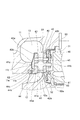
本開示の第1実施形態に係る可変容量型過給機について、図1〜図3を参照しながら説明する。図1に示されるように、第1実施形態に係る可変容量型過給機1は、タービン10とコンプレッサ20(遠心圧縮機)とを備えている。タービン10は、タービンハウジング11と、タービンハウジング11に収容されたタービン翼車12と、を備えている。コンプレッサ20は、コンプレッサハウジング21と、コンプレッサハウジング21に収容されたコンプレッサ翼車22と、を備えている。タービン翼車12は軸線X方向に沿って延びる回転軸32の一端に設けられており、コンプレッサ翼車22は回転軸32の他端に設けられている。タービンハウジング11とコンプレッサハウジング21との間には、ベアリングハウジング31が設けられている。回転軸32は、ベアリングハウジング31に回転自在に支持されており、回転軸32、タービン翼車12及びコンプレッサ翼車22が一体の回転体として回転する。First Embodiment
A variable displacement turbocharger according to a first embodiment of the present disclosure will be described with reference to FIGS. 1 to 3. As shown in FIG. 1, the variable displacement supercharger 1 according to the first embodiment includes a
タービンハウジング11には、排気ガス流入口(図示せず)及び排気ガス流出口16が設けられている。内燃機関(図示せず)から排出された排気ガスが、排気ガス流入口(図示せず)を通じてタービンハウジング11内に設けられた渦巻状のタービンスクロール流路13に流入し、タービン翼車12を回転させ、その後、排気ガス流出口16を通じてタービンハウジング11外に流出する。タービンハウジング11内にはタービン翼車12側へ供給される排気ガスの流路面積(流量)を制御する可変ノズルユニット40が設けられる。この点については後述する。なお、以下の実施形態では、タービンハウジング11内での排気ガス流れに関して、排気ガス流入口に近いタービンスクロール流路13側を「上流」とし、排気ガス流出口16に近いタービン翼車12側を「下流」として説明する場合がある。
The
コンプレッサハウジング21には、吸入口25及び吐出口(図示せず)が設けられている。上記のようにタービン翼車12が回転すると、回転軸32を介してコンプレッサ翼車22が回転する。コンプレッサ翼車22の回転によって、外部の空気が吸入口25を介して吸入され、コンプレッサスクロール流路を通り、吐出口から吐出される。吐出口から吐出された圧縮空気は、前述の内燃機関に供給される。
The
ベアリングハウジング31には、回転軸32を回転自在に支持するラジアルベアリング33及び一対のスラストベアリング34が設けられる。
The bearing
次に、タービンハウジング11に含まれる可変ノズルユニット40について図1〜図3を参照しながら説明する。
Next, the
可変ノズルユニット40は、軸線Xを中心とした周方向に間隔をおいて配置された複数の可変ノズル41と、これらの可変ノズル41を軸線X方向に挟むようにして保持する第1ノズルリング42及び第2ノズルリング43と、複数の可変ノズル41に固定されて半径方向外側に延びる複数のリンク部材45と、リンク部材45の半径方向外側の端部に係合する駆動リング46と、排気ガスの漏れを抑制するためのシールリング47(第1シール部材)及びシールカバー48(第2シール部材)と、を有する。図1から分かるように、この可変ノズルユニット40は、タービン翼車12の半径方向外側であって、タービンスクロール流路13からタービン翼車12側へ向かう排気ガス流路に対して複数の可変ノズル41が配置するように取り付けられる。
The
可変ノズルユニット40は、モータ又はシリンダ(図示せず)等の駆動が動力伝達機構49を介して伝達されることによって、駆動リング46が周方向に回転することで、駆動リング46にそれぞれ係合している複数のリンク部材45が周方向に回転する。これにより、複数のリンク部材45に対してそれぞれ固定された複数の可変ノズル41が回転(揺動)する。可変ノズルユニット40は、複数の可変ノズル41の回転量を制御することで、上流のタービンスクロール流路13側から下流のタービン翼車12側への排気ガス流量を制御することが可能となる。
The
次に、可変ノズルユニット40の各部について図2及び図3を参照しながら、説明する。第1ノズルリング42は、タービン翼車12の径方向外側であって、タービン翼車12の翼端部12aに対してベアリングハウジング31側となる位置に設けられる。第1ノズルリング42は、後述の第2ノズルリング43とX軸方向に沿って対向配置される。第1ノズルリング42は、軸線Xを中心とした周方向に間隔をおいて設けられた複数の貫通孔である第1支持孔61を有する。第1支持孔61は、可変ノズル41を支持するための貫通孔である。
Next, each part of the
また、第1ノズルリング42は、第1ノズルリング42のベアリングハウジング31側(背面側)において、第1ノズルリング42よりも外径が大きいサポートリング50に対して固定される。サポートリング50は、その外周縁がタービンハウジング11とベアリングハウジング31とによって挟み込まれる。これにより、サポートリング50及びサポートリング50に対して固定された第1ノズルリング42がタービンハウジング11及びベアリングハウジング31に対して固定される。
The
第1ノズルリング42の内周側であってタービン翼車12の背面(ベアリングハウジング側の面)と対向する位置には、タービン10側から伝わる熱を遮るための略円環状の遮熱板52が設けられる。図2に示すように、遮熱板52の内周縁は、ベアリングハウジング31を囲っている。また、遮熱板52の外周縁には切欠き52aが形成されていて、遮熱板52の外周縁は、この切欠き52aにおいて第1ノズルリング42の内周縁に対して当接する。これにより、タービン10側からベアリングハウジング31及びコンプレッサ20側への伝熱が抑制される。なお、遮熱板52の外周側とベアリングハウジング31との間にはウェーブワッシャー53(波ワッシャー)が設けられ、ウェーブワッシャー53によって遮熱板52が第1ノズルリング42側へ押圧される。このように、遮熱板52及びウェーブワッシャー53は、第1ノズルリング42をベアリングハウジング31側から支持している。ウェーブワッシャー53は、側面から見たときに波形をなしていて、ベアリングハウジング31に対して当接する部分と遮熱板52に対して当接する部分とを有し、これらの間の距離を確保すると共に弾性が調整されている。これにより、ウェーブワッシャー53によるばね力によって遮熱板52及び第1ノズルリング42が変形することを防止している。また、ウェーブワッシャー53によって、遮熱板52を介して、第1ノズルリング42を第2ノズルリング43に対して押圧する構成とすることで、第1ノズルリング42と第2ノズルリング43との間のシール性が向上する。
A substantially
第2ノズルリング43は、第1ノズルリング42に対して軸線X方向に沿って離間して設けられる。第1ノズルリング42と第2ノズルリング43とは、軸線Xを中心とした周方向に間隔をおいて配置された複数の連結ピン51により所定の距離離間した状態で接続される。また、第2ノズルリング43には、第1ノズルリング42における複数の第1支持孔61に対応して、軸線Xを中心とした周方向に間隔をおいて設けられた複数の貫通孔である第2支持孔62を有する。
The
環状の第2ノズルリング43の内周端には、軸線X方向に沿って排気ガス流出口16側へ延びるシュラウド部44が形成される。シュラウド部44において、その内周面44aは、タービン翼車12の翼端部12aと対向すると共に翼端部12aの形状に沿った形状を有する。
At an inner peripheral end of the annular
また、シュラウド部44の外周面44bは、タービンハウジング11の内周面11aと対向する。内周面11aは、タービン翼車12から排気ガス流出口16側へ延びる流路に対してシュラウド部44の形状に応じて切り欠かれることで形成された面である。これにより、第2ノズルリング43は、背面43b及びシュラウド部44の外周面44bにおいてタービンハウジング11と対向する。また、第2ノズルリング43のシュラウド部44の外周面44bの内周端における第2ノズルリング43とタービンハウジング11との境界部分は、タービン翼車12の翼端部12aよりも下流側(排気ガス流出口16側)に設けられる。
Further, the outer
タービンハウジング11の内周面11aと第2ノズルリング43との間には、シールリング47が設けられる。シールリング47は、第2ノズルリング43における可変ノズル41側の対向面43aとは逆側の背面43b側と、タービン翼車12との間が連通することを防ぐために設けられるシール部材の1つである。シールリング47としては、耐熱性を有する金属材料を用いることができるが、運転時の合口隙間がより小さくなるように、その材料及び形状は適宜変更することができる。また、シールリング47の数についても運転状況等に応じて適宜変更することができる。本実施形態におけるシールリング47は、図3に示すように、シュラウド部44の外周面44bに形成された溝44cに収容される。これにより、タービンハウジング11の内周面11aと第2ノズルリング43におけるシュラウド部44の外周面44bとの間を塞ぐようにシールリング47が配置される。すなわち、シールリング47は、第2支持孔62よりもタービン翼車12側に設けられる。
A
第2ノズルリング43のシュラウド部44の外周面44bに対向するように設けられたタービンハウジング11の内周面11aと、タービンスクロール流路13の内壁部分との間には、第2ノズルリング43における背面43bと対向する段差面11cが設けられる。段差面11cは、第2ノズルリング43の背面43bに対して離間して形成される。また、段差面11cと内周面11aとの間には、内周面11a及び段差面11cに連続する外周面11bが形成される。この外周面11b及び段差面11cと、第2ノズルリング43の背面43bとの間には、シールカバー48が設けられる。
A
シールカバー48は、第2ノズルリング43の背面43b側と、タービン翼車12との間が連通することを防ぐために設けられるシール部材の1つである。シールカバー48は、例えば円環状の板金を折り曲げ加工することにより形成することができる。シールカバー48としては、例えば、SUS304又はSUS310等のステンレス鋼等の金属材料を適宜選択して使用することができる。
The
シールカバー48は、タービンハウジング11の段差面11cと当接する支持部48aと、支持部48aの外周側に形成され支持部48aに対して折り曲げられて第2ノズルリング43側へ傾斜する傾斜部48bと、傾斜部48bの外周側で傾斜部48bに対して折り曲げられて第2ノズルリング43の背面43bと当接するリング当接部48cと、リング当接部48cの外周側に形成されて第2ノズルリング43の外周縁43dと当接するリング支持部48dとを備える。図3に示すように、シールカバー48は、支持部48aでタービンハウジング11の段差面11cと当接すると共に、リング当接部48c及びリング支持部48dで第2ノズルリング43と当接した状態で、タービンハウジング11と第2ノズルリング43との間に支持される。これにより、第2支持孔62よりもタービンスクロール流路13側において、タービンスクロール流路13側とタービン翼車12との間がシールカバー48によって塞がれる。
The
図3に示すように、シールカバー48には、内周側の支持部48aと外周側のリング当接部48cとの間に傾斜部48bが形成されている。これにより、シールカバー48は、第2ノズルリング43を支持する皿ばねとして機能する。本実施形態で示すシールカバー48では、皿ばね状のシールカバー48を採用することにより、タービンスクロール流路13側とタービン翼車12との間に形成される隙間に対するシール性が高められている。また、傾斜部48bを従来のシールカバー48よりも長く確保し、且つ、リング当接部48cが第2ノズルリング43の外周側と当接するような構成とすることにより、皿ばねの弾性力を制御して、第2ノズルリング43にかかるばね力が大きくなり過ぎないようにしている。このような構成とすることで、運転時等の高熱環境下において、第2ノズルリング43を含む可変ノズルユニット40がばね力を受けて熱変形することを防止することができる。
As shown in FIG. 3, in the
また、シールカバー48では、その外周端であってリング当接部48cから連続して形成されたリング支持部48dが、第2ノズルリング43を外側から囲うように取り付けられる。これにより、シールカバー48による第2ノズルリング43の支持性能が高められている。なお、リング支持部48dは、第2ノズルリング43の外側を全周に亘って囲う必要はなく、適宜隙間等が設けられていてもよい。その場合であっても、リング支持部48dを備えていない場合と比較して、シールカバー48による第2ノズルリング43の支持性能が向上する。
Further, in the
また、連結ピン51の第2ノズルリング43側(他方側)は、例えばかしめなどで第2ノズルリング43の背面43b側に固定されるが、連結ピン51の他方側端面は背面43bと僅かに段差が生じる場合が考えられる。すなわち、第2ノズルリング43の背面43b側表面に段差が形成される可能性がある。ここで、シールカバー48は、図3に示すように、リング当接部48cの内周端を連結ピン51よりも径方向外側に位置するように構成とされていることで、第2ノズルリング43の背面43bにおいて、背面43bと連結ピン51端面との段差を回避して、リング当接部48cが第2ノズルリング43の外周側と当接することができる。したがって、第2ノズルリング43の背面43b側へ漏れる排気ガス流れを防止して、背面43bと連結ピン51端面との段差にシールカバー48が当接している場合と比較して、タービンスクロール流路13とタービン翼車12側との間に形成される隙間に対するシール性をさらに高めることができる。
Further, the
このように、第2ノズルリング43の背面43b及び内周側のシュラウド部44側において、タービンスクロール流路13とタービン翼車12側とが連通することを防止するために、2つのシール部材、すなわち、シールリング47及びシールカバー48が取り付けられる。これにより、タービンスクロール流路13を流れる排気ガスは、第2ノズルリング43の対向面43a側の可変ノズル41側を通過して、タービン翼車12側へ流入する。
Thus, in order to prevent communication between the
なお、図2に示すように、第1ノズルリング42側では、第1ノズルリング42の外周縁とタービンハウジング11との間に隙間があるため、排気ガスが第1ノズルリング42の背面42b側に流入可能である。しかしながら、第1ノズルリング42の背面42b側とタービン翼車12側との間には、遮熱板52及びウェーブワッシャー53が設けられ(図2参照)、連通が防止されているので、背面42b側からの排気ガスの流入が規制される。
Note that, as shown in FIG. 2, since there is a gap between the outer peripheral edge of the
可変ノズル41は、第1ノズルリング42と第2ノズルリング43との間に複数設けられる。可変ノズル41は、タービンスクロール流路13側とタービン翼車12側との間の排気ガス流路上に設けられて軸線Xと平行な軸心に沿って回動可能な平板状のノズル部41aと、ノズル部41aの回動軸心を構成する第1ノズル軸41b及び第2ノズル軸41cと、を備える。このうち、第1ノズル軸41bは、ノズル部41aから第1ノズルリング42側(一方側)に延びる軸であって、第1ノズルリング42の第1支持孔61に挿入されて回動可能に支持される。また、第1ノズル軸41bは、第1ノズルリング42のベアリングハウジング31側(背面側)において、リンク部材45に対して固定される。一方、第2ノズル軸41cは、ノズル部41aから第2ノズルリング43側(他方側)に延びる軸であって、第2ノズルリング43の第2支持孔62に挿入されて回動可能に支持される。第1ノズル軸41b及び第2ノズル軸41cは同心上に延びる。すなわち、可変ノズル41は、軸線X方向に沿ってノズル部41aを挟んで配置された第1ノズルリング42及び第2ノズルリング43によって回動可能に両側から支持される所謂両持ちの可変ノズルである。
A plurality of
図3に示すように、可変ノズル41における第1ノズル軸41bの根元部分(ノズル部41a側の端部)には、第1ノズルリング42における可変ノズル41側の対向面42aに沿って第1ノズル軸41bから外方に突出すると共に、対向面42aと接触可能な第1鍔部41dが設けられる。また、可変ノズル41における第2ノズル軸41cの根元部分(ノズル部41a側の端部)には、第2ノズルリング43における可変ノズル41側の対向面43aに沿って第2ノズル軸41cから外方に突出すると共に、対向面43aと接触可能な第2鍔部41eが設けられる。第1鍔部41d及び第2鍔部41eを備えることによって、可変ノズル41のノズル部41aに対する排気ガス圧等による可変ノズル41の回動軸のずれ等を防ぐことができる。なお、第1鍔部41d及び第2鍔部41eを備えていなくてもよい。
As shown in FIG. 3, at a root portion (an end on the
ここで、本実施形態に係る可変ノズルユニット40を含む可変容量型過給機1では、2つのシール部材として、シールリング47(第1シール部材)及びシールカバー48(第2シール部材)が設けられている。これらの部材は、第2ノズルリング43の背面43b及び内周側のシュラウド部44の外周面44b側からの排気ガスの流通を抑制することができる。これにより、過給機全体としての性能の向上が図られる。この点について、図3及び図4を参照しながら説明する。
Here, in the variable displacement supercharger 1 including the
図4は、従来型の可変容量型過給機の断面図であり、図2に対応するものである。図4に示す可変容量型過給機2では、可変ノズルユニット70の構造が、本実施形態に係る可変容量型過給機1の可変ノズルユニット40の構造と一部相違する。例えば、第2ノズルリング73のシュラウド部74の外周面とタービンハウジングとの間にシールリング47に対応するシール部材を備えていない点が相違する。
FIG. 4 is a cross-sectional view of a conventional variable displacement turbocharger, corresponding to FIG. In the
従来型の可変容量型過給機2では、シールカバー78が設けられていることで、タービンスクロール流路13から第2ノズルリング73の背面73b側を経て直接タービン翼車12側へ向かう排気ガス流路は塞がれている。しかしながら、第2ノズルリング73に取り付けられる可変ノズル71の第2ノズル軸71cの周囲と第2ノズルリング73との間には、ノズルの回動性を確保するための隙間が確保されるため、第2ノズル軸71cを支持する第2支持孔75を介した排気ガス流れが生じることが考えられる。この場合、タービンスクロール流路13からの排気ガスは、第2ノズルリング73の対向面73a側から第2支持孔75を経て背面73b側へ向かい、背面73b側を伝って、シュラウド部74とタービンハウジング11との間からタービン翼車12側の流路へ流れてしまう。この場合、可変ノズル71を通過しない排気ガス流れが生じると、可変ノズル71を利用した流量制御を排気ガス全体に適用できないことになるため、可変容量型過給機全体としての性能を十分に発揮できないことが考えられる。また、排気ガスにはすす等の異物が含まれるため、排気ガスが第2支持孔75及び第2ノズルリング73の背面73b側にも流出する場合には、背面73b側及びシュラウド部74の外周側にもすす等の異物が付着することが考えられる。この場合、異物の付着等による性能低下(例えば、可変ノズルの作動性の低下)が生じることが考えられる。
In the
これに対して、本実施形態に係る可変ノズルユニット40を含む可変容量型過給機1では、第2ノズルリング43の背面43b及びシュラウド部44の外周面44b側において、タービンスクロール流路13とタービン翼車12側との間に複数のシール部材が設けられている。複数のシール部材を備えることで、第2ノズルリング43の背面43b及びシュラウド部44の外周面44b側を経由する排気ガス流れの形成を防止することができる。また、本実施形態に係る可変ノズルユニット40を含む可変容量型過給機1では、複数のシール部材の1つであるシールリング47が第2ノズルリング43の第2支持孔62よりも下流側(タービン翼車12側)に設けられていることを特徴とする。シールカバー48を設けることで、タービンスクロール流路13から直接タービン翼車12側へ向かう排気ガス流路が塞がれていることに加えて、シールリング47を設けることで、第2ノズルリング43の第2支持孔62を経て背面43b側からタービン翼車12側の下流へ向かう排気ガス流が生じることを防ぐことができる。この結果、可変ノズル41を通過する排気ガスの流量を増大することができるため、過給効率が向上する。
On the other hand, in the variable displacement supercharger 1 including the
また、第2ノズル軸41cが挿入される第2支持孔62に対して、シールカバー48は上流側(タービンスクロール流路13側)に設けられると共に、シールリング47は下流側(タービン翼車12側)に設けられる。このようなシールリング47及びシールカバー48を同時に設けることで、第2ノズルリング43の背面43b及びシュラウド部44の外周面44bにおいて、第2ノズル軸41cが挿入される第2支持孔62の周囲に、シールリング47、シールカバー48及びタービンハウジング11に囲われた空間S(図3参照)が形成される。空間S内の圧力は、第2支持孔62によって接続されたノズル部41a側と概ね同じになるために、第2支持孔62を経て空間Sに対して排気ガスが流れることも抑制される。また、シールカバー48を設けない場合と比較して、第2ノズルリング43の背面43bが、タービンスクロール流路13に露出しないため、可変ノズル41を通過する前の排気ガスと接触することによる異物の付着等を防止することができる。この結果、可変ノズルの作動性の低下等による過給効率の低下を防ぐことができる。したがって、本実施形態に係る可変ノズルユニット40及び可変容量型過給機1では、過給効率の更なる向上が図られると共に、安定した過給効率での長期運転が可能となると考えられる。
Further, the
また、本実施形態の可変ノズルユニット40におけるシール部材の一つとして用いられるシールカバー48は、第2ノズルリング43を支持する皿ばねとして機能する。シールカバー48が皿ばね状であることにより、タービンスクロール流路13側とタービン翼車12との間に形成される隙間に対するシール性を高められている。また、シールカバー48によれば、従来型のシールカバー78(図4参照)と比較して、傾斜部48bを十分に確保し、且つ、リング当接部48cが第2ノズルリング43の外周側と当接するような構成とすることができる。この場合、可変ノズルユニット40の熱変形等を防止するために第2ノズルリング43にかかるばね力をより好適に制御することができる。
Further, the
また、シールカバー48によって、第2ノズルリング43は、第1ノズルリング42側へ押圧される。そして、第1ノズルリング42は、遮熱板52を介してウェーブワッシャー53によって第2ノズルリング43側へ押圧される。このように、第1ノズルリング42及び第2ノズルリング43が互いに近寄るように両側から弾性を有する部材に押圧された状態で支持される構成を備えることで、可変ノズルユニット40全体としてのシール性も向上され、過給効率の向上が図られる。
Further, the
なお、シールカバー48によるシール性を高めるためにタービンハウジング11の形状を変更してもよい。図5は、タービンハウジング11の形状の変更例を示す断面図であり、シールカバー48の内周端近傍の拡大図である。図5に示す変形例では、タービンハウジング11の段差面11cよりも内周側の外周面11bに溝部11dが形成されている。溝部11dは、シールカバー48の支持部48aから連続する内周端48eを受け入れ可能な位置に設けられる。シールカバー48は、可変ノズルユニット40を含む可変容量型過給機1の組み立て時に、シールカバー48の内周端48eがタービンハウジング11の溝部11d内に収容された状態で取り付けられてもよい。また、シールカバー48の内周端48eは、溝部11dよりも段差面11c側において外周面11bと当接するように、シールカバー48が取り付けられてもよい。
The shape of the
可変容量型過給機1の運転時には、シールカバー48に対してタービンスクロール流路13側の領域の内圧は、シールカバー48に対して第2支持孔62側の領域の内圧に比べて高くなる。したがって、運転時には、シールカバー48に対して圧力差に由来して、タービンスクロール流路13側からの流体荷重がかかる。さらに、可変容量型過給機1の運転時には、シールカバー48周辺は高温となる。このため、エンジン開発等により、シールカバー48にかかる流体荷重やシールカバー48の周辺温度がより厳しい条件になると、流体荷重を受けたシールカバー48がクリープ変形を起こす可能性が考えられる。これに対して、図5に示す変形例では、シールカバー48の内周端48eがタービンハウジング11の溝部11d内に収容可能な構成を備える。これにより、仮にシールカバー48が変形したとしても、溝部11dにシールカバー48の内周端48eが収容されることで、シールカバー48のさらなる変形を防ぐことができる。したがって、タービンスクロール流路13側とタービン翼車12との間に形成される隙間に対するシール性を維持することができる。
During operation of the variable displacement supercharger 1, the internal pressure in the region on the turbine
(第2実施形態)
次に、第2実施形態に係る可変ノズルユニットを含む可変容量型過給機について、図6を参照しながら説明する。第2実施形態に係る可変容量型過給機は、第1実施形態に係る可変容量型過給機と比較して以下の点が相違する。すなわち、第2実施形態に係る可変容量型過給機3における可変ノズルユニット400では、可変ノズル41及び第1ノズルリング42の形状は、第1実施形態における可変ノズルユニット40と同じであるが、第2ノズルリング430の形状が可変ノズルユニット40における第2ノズルリング43とは異なる。また、ウェーブワッシャー53に代えて皿ばね54が遮熱板52を支持する点も第1実施形態における可変ノズルユニット40とは相違する。Second Embodiment
Next, a variable displacement supercharger including a variable nozzle unit according to a second embodiment will be described with reference to FIG. The variable displacement supercharger according to the second embodiment is different from the variable displacement supercharger according to the first embodiment in the following points. That is, in the
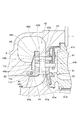
図6に示すように、第2実施形態に係る可変容量型過給機3における可変ノズルユニット400では、第2ノズルリング430はシュラウド部を備えておらず、タービンハウジング11側にシュラウド部が設けられる。すなわち、円環状の第2ノズルリング430の内周側には、タービンハウジング11のうち、タービンスクロール流路13の内側の内壁部分を構成しながら、軸線X方向に沿って延びるシュラウド部17が形成される。
As shown in FIG. 6, in the
タービンハウジング11のシュラウド部17において、その内周面17aは、タービン翼車12の翼端部12aと対向すると共に翼端部12aの形状に沿った形状を有する。また、シュラウド部17の外周面17bは、第2ノズルリング430の内周縁43cと対向する。このように、第2ノズルリング430は、背面43b及び内周縁43cにおいてタービンハウジング11と対向する。また、第2ノズルリング430の内周縁43cにおける第2ノズルリング430とタービンハウジング11との境界部分は、タービン翼車12の翼端部12aよりも上流側(可変ノズル41に近い側)に設けられる。
In the
外周面17bと第2ノズルリング430との間には、シールリング47が設けられる。シールリング47の形状は第1実施形態における可変ノズルユニット40におけるシールリングと同様であるが、取り付け位置が異なる。すなわち、シールリング47は、図6に示すように、シュラウド部17の外周面17bに形成された溝17dに収容される。これにより、シュラウド部17の外周面17bと第2ノズルリング430の内周縁43cとの間を塞ぐようにシールリング47が配置される。
A
また、タービンハウジング11のシュラウド部17において、その外周面17bと、タービンスクロール流路13の内壁部分との間には、第2ノズルリング430における背面43bと対向する段差面17cが設けられる。段差面17cは、第2ノズルリング430の背面43bに対して離間して形成される。シュラウド部17の段差面17cと、第2ノズルリング430の背面43bとの間には、シールカバー48が設けられる。シールカバー48の形状は第1実施形態における可変ノズルユニット40におけるシールカバーと同様である。図6に示すように、シールカバー48は、支持部48aでシュラウド部17の段差面17cと当接すると共に、リング当接部48c及びリング支持部48dで第2ノズルリング430と当接した状態で、タービンハウジング11のシュラウド部17と第2ノズルリング430との間に支持される。これにより、タービンスクロール流路13側とタービン翼車12との間がシールカバー48によって塞がれる。このシールカバー48は、第1実施形態と同様に、第2ノズルリング430を支持する皿ばねとして機能する。
Further, in the
このように、第2ノズルリング430の背面43b及び内周縁43c側において、タービンスクロール流路13とタービン翼車12側とが連通することを防止するために、2つのシール部材、すなわち、シールリング47及びシールカバー48が取り付けられる。これにより、タービンスクロール流路13を流れる排気ガスは、第2ノズルリング430の対向面43a側の可変ノズル41側を通過して、タービン翼車12側へ流入する。
Thus, in order to prevent communication between the
なお、本実施形態に係る可変ノズルユニット400では、遮熱板52を介して第1ノズルリング42を支持する弾性部材として、ウェーブワッシャー53に代えて皿ばね54が用いられている。皿ばね54もウェーブワッシャー53と同様に、ばね力によって遮熱板52及び第1ノズルリング42が変形することを防止している。また、皿ばね54によって、遮熱板52を介して、第1ノズルリング42を第2ノズルリング430に対して押圧する構成とすることで、第1ノズルリング42と第2ノズルリング430との間のシール性が向上する。なお、遮熱板52を介して第1ノズルリング42を支持する部材はこれらに限定されず、適宜変更することができる。
In the
ここで、本実施形態に係る可変ノズルユニット400を含む可変容量型過給機3においても、2つのシール部材として、シールリング47(第1シール部材)及びシールカバー48(第2シール部材)が設けられている。これらの部材は、第2ノズルリング430の背面43b及び内周縁43c側からの排気ガスの流通を抑制することができる。これにより、過給機全体としての性能の向上及び作業性の向上が図られる。この点は、第1実施形態に係る可変容量型過給機1の可変ノズルユニット40と同様である。
Here, also in the
さらに、本実施形態における可変容量型過給機3では、タービン翼車12の形状に対応したシュラウド部17がタービンハウジング11により形成されている点が、第1実施形態の可変容量型過給機1及び従来型の可変容量型過給機2と相違する。例えば、第1実施形態の可変容量型過給機1のように、タービン翼車12の翼形状に沿ったシュラウド部44が第2ノズルリング430によって構成されている場合、仮に可変ノズル41を通過しない排気ガス流れが第2ノズルリング430の背面43bに形成された場合、第2ノズルリング430とタービンハウジング11との境界部のうちタービン翼車12側の端部は、タービン翼車12よりも下流(排気ガス流出口)側となる。これに対して、本実施形態に係る可変容量型過給機3では、シュラウド部17がタービンハウジング11によって形成されていることで、第2ノズルリング430の背面43bから連続して第2ノズルリング430の内周縁43cに形成されるタービンハウジング11との境界部分が、タービン翼車12の翼端部12aよりも上流側(可変ノズル41に近い側)に設けられる。これにより、仮にシールリング47又はシールカバー48が劣化して、第2ノズルリング430の背面43b及び内周縁43c側に排気ガス流れが形成されたとしても、その出口がタービン翼車12よりも上流側にあることで、背面43b及び内周縁43c側の排気ガス流れもタービン翼車12の回転に寄与することが可能となり、過給効率の低下を防止することができるという効果が得られる。
Furthermore, in the
以上、本開示の実施形態に係る可変ノズルユニット及び可変容量型過給機について説明したが、本開示は必ずしも上述した実施形態に限定されるものではなく、その要旨を逸脱しない範囲で種々の変更を行うことができる。 As mentioned above, although the variable nozzle unit and variable displacement type supercharger concerning the embodiment of this indication were explained, this indication is not necessarily limited to the embodiment mentioned above, and various changes in the range which does not deviate from the gist It can be performed.
例えば、上述の実施形態に係る可変ノズルユニット及び可変容量型過給機の形状は一例に過ぎず、本開示の趣旨を脱しない範囲で適宜変更してよい。例えば、本実施形態においては、複数のシール部材として、シールリング47とシールカバー48と備える構成について説明したが、シール部材の数及び形状は適宜変更することができる。複数のシール部材のうちの少なくとも1つが、第2ノズルリング43、430の背面側であって且つ第2支持孔62よりも下流側において、タービンハウジング11との隙間に配置される構成であればよい。
For example, the shapes of the variable nozzle unit and the variable displacement supercharger according to the above-described embodiment are merely examples, and may be appropriately changed without departing from the scope of the present disclosure. For example, in the present embodiment, the configuration in which the
さらに、タービンハウジング11、第1ノズルリング42、及び第2ノズルリング43、430等の形状、並びに、可変ノズル41を回転させるためのリンク部材45等を含むリンク機構の構成についても適宜変更することができる。
Furthermore, the configuration of the link mechanism including the shapes of the
本開示によれば、過給効率の更なる向上が図られた可変ノズルユニット及び可変容量型過給機が提供される。 According to the present disclosure, a variable nozzle unit and a variable displacement supercharger are provided in which the supercharging efficiency is further improved.
1、2、3 可変容量型過給機
10 タービン
11 タービンハウジング
12 タービン翼車
12a 翼端部
13 タービンスクロール流路
16 排気ガス流出口
17 シュラウド部
17a 内周面
17b 外周面
17c 段差面
17d 溝
20 コンプレッサ
21 コンプレッサハウジング
31 ベアリングハウジング
32 回転軸
40 可変ノズルユニット
41 可変ノズル
41a ノズル部
41b 第1ノズル軸
41c 第2ノズル軸
42 第1ノズルリング
42a 対向面
42b 背面
43 第2ノズルリング
43a 対向面
43b 背面
44 シュラウド部
44a 内周面
44b 外周面
44c 溝
45 リンク部材
46 駆動リング
47 シールリング(シール部材の一例)
48 シールカバー(シール部材の一例)
48a 支持部
48b 傾斜部
48c リング当接部
48d リング支持部
48e 内周端
49 動力伝達機構
50 サポートリング
51 連結ピン
52 遮熱板
53 ウェーブワッシャー
54 皿ばね
61 第1支持孔
62 第2支持孔
70 可変ノズルユニット
71 可変ノズル
71c 第2ノズル軸
72 第1ノズルリング
73 第2ノズルリング
74 シュラウド部
75 第2支持孔
400 可変ノズルユニット
430 第2ノズルリング1, 2, 3
48 Seal cover (example of seal member)
Claims (3)
前記可変ノズルユニットは、前記タービンハウジング内に配置され、第1支持孔が複数形成された第1ノズルリングと、前記第1ノズルリングに対して前記タービン翼車の軸線方向に沿って離間した位置に対向配置され、前記第1支持孔に対応した貫通孔である第2支持孔が複数形成された第2ノズルリングと、前記第1ノズルリングと前記第2ノズルリングとによって回動可能に支持される複数の可変ノズルと、前記第2ノズルリングにおける前記タービンハウジングと対向する面に沿って前記タービンスクロール流路と前記タービン翼車側との間に配置された複数のシール部材と、を備え、
前記可変ノズルは、一方側に延びる第1ノズル軸が前記第1支持孔に回動可能に支持されると共に、他方側に延びる第2ノズル軸が前記第2支持孔に回動可能に支持され、
前記複数のシール部材に含まれる第1シール部材は、前記第2支持孔よりも前記タービン翼車側に設けられ、
前記複数のシール部材に含まれる第2シール部材は、前記第2支持孔よりも前記タービンスクロール流路側に設けられ、内周側で前記タービンハウジングと当接すると共に、外周側で前記第2ノズルリングと当接して、前記第2ノズルリングを押圧する皿ばね状であり、
前記第1ノズルリングと前記第2ノズルリングとは連結ピンにより固定され、
前記第2シール部材は、前記第2ノズルリングとの当接部の内周端が、前記連結ピンの取り付け位置よりも径方向外側に位置する可変容量型過給機。 A variable displacement turbocharger is disposed between a turbine scroll passage and a turbine wheel in a turbine housing of a variable displacement turbocharger, and changes a flow passage area of exhaust gas supplied from the turbine scroll passage to the turbine wheel side. A variable displacement turbocharger including a nozzle unit, wherein
The variable nozzle unit is disposed in the turbine housing, and has a first nozzle ring formed with a plurality of first support holes, and a position spaced apart from the first nozzle ring along the axial direction of the turbine wheel. And rotatably supported by a second nozzle ring on which a plurality of second support holes, which are through holes corresponding to the first support holes, are formed to face each other, and the first nozzle ring and the second nozzle ring A plurality of variable nozzles, and a plurality of seal members disposed between the turbine scroll passage and the turbine wheel side along a surface of the second nozzle ring facing the turbine housing. ,
The variable nozzle has a first nozzle shaft extending to one side rotatably supported by the first support hole, and a second nozzle shaft extending to the other side rotatably supported by the second support hole. ,
The first seal member included in the plurality of seal members is provided closer to the turbine wheel than the second support hole,
A second seal member included in the plurality of seal members is provided closer to the turbine scroll flow passage than the second support hole, and abuts the turbine housing on the inner peripheral side, and the second nozzle ring on the outer peripheral side And a disc spring shape for pressing the second nozzle ring in contact with the
The first nozzle ring and the second nozzle ring are fixed by connection pins,
It said second sealing member, the inner peripheral end of the contact portion between the second nozzle ring, variable capacity supercharger you located radially outward from the mounting position of the connection pin.
前記可変ノズルユニットは、前記タービンハウジング内に配置され、第1支持孔が複数形成された第1ノズルリングと、前記第1ノズルリングに対して前記タービン翼車の軸線方向に沿って離間した位置に対向配置され、前記第1支持孔に対応した貫通孔である第2支持孔が複数形成された第2ノズルリングと、前記第1ノズルリングと前記第2ノズルリングとによって回動可能に支持される複数の可変ノズルと、前記第2ノズルリングにおける前記タービンハウジングと対向する面に沿って前記タービンスクロール流路と前記タービン翼車側との間に配置された複数のシール部材と、を備え、
前記可変ノズルは、一方側に延びる第1ノズル軸が前記第1支持孔に回動可能に支持されると共に、他方側に延びる第2ノズル軸が前記第2支持孔に回動可能に支持され、
前記複数のシール部材に含まれる第1シール部材は、前記第2支持孔よりも前記タービン翼車側に設けられ、
前記複数のシール部材に含まれる第2シール部材は、前記第2支持孔よりも前記タービンスクロール流路側に設けられ、内周側で前記タービンハウジングと当接すると共に、外周側で前記第2ノズルリングと当接して、前記第2ノズルリングを押圧する皿ばね状であり、
前記タービンハウジングは、前記第2シール部材の内周端を収容可能な溝部を有し、
前記第1ノズルリングと前記第2ノズルリングとは連結ピンにより固定され、
前記第2シール部材は、前記第2ノズルリングとの当接部の内周端が、前記連結ピンの取り付け位置よりも径方向外側に位置する可変容量型過給機。 Variable displacement type provided with a variable nozzle unit disposed between a turbine scroll passage in a turbine housing and a turbine wheel for changing a flow passage area of exhaust gas supplied from the turbine scroll passage to the turbine wheel side Being a supercharger,
The variable nozzle unit is disposed in the turbine housing, and has a first nozzle ring formed with a plurality of first support holes, and a position spaced apart from the first nozzle ring along the axial direction of the turbine wheel. And rotatably supported by a second nozzle ring on which a plurality of second support holes, which are through holes corresponding to the first support holes, are formed to face each other, and the first nozzle ring and the second nozzle ring A plurality of variable nozzles, and a plurality of seal members disposed between the turbine scroll passage and the turbine wheel side along a surface of the second nozzle ring facing the turbine housing. ,
The variable nozzle has a first nozzle shaft extending to one side rotatably supported by the first support hole, and a second nozzle shaft extending to the other side rotatably supported by the second support hole. ,
The first seal member included in the plurality of seal members is provided closer to the turbine wheel than the second support hole,
A second seal member included in the plurality of seal members is provided closer to the turbine scroll flow passage than the second support hole, and abuts the turbine housing on the inner peripheral side, and the second nozzle ring on the outer peripheral side And a disc spring shape for pressing the second nozzle ring in contact with the
The turbine housing, have a can accommodate grooves of the inner peripheral end of the second sealing member,
The first nozzle ring and the second nozzle ring are fixed by connection pins,
The variable displacement supercharger wherein an inner peripheral end of a contact portion of the second seal member with the second nozzle ring is positioned radially outward of an attachment position of the connection pin .
Applications Claiming Priority (3)
| Application Number | Priority Date | Filing Date | Title |
|---|---|---|---|
| JP2014203956 | 2014-10-02 | ||
| JP2014203956 | 2014-10-02 | ||
| PCT/JP2015/076504 WO2016052231A1 (en) | 2014-10-02 | 2015-09-17 | Variable nozzle unit and variable-capacity supercharger |
Publications (2)
| Publication Number | Publication Date |
|---|---|
| JPWO2016052231A1 JPWO2016052231A1 (en) | 2017-04-27 |
| JP6542246B2 true JP6542246B2 (en) | 2019-07-10 |
Family
ID=55630271
Family Applications (1)
| Application Number | Title | Priority Date | Filing Date |
|---|---|---|---|
| JP2016551928A Active JP6542246B2 (en) | 2014-10-02 | 2015-09-17 | Variable displacement turbocharger |
Country Status (5)
| Country | Link |
|---|---|
| US (1) | US10465601B2 (en) |
| JP (1) | JP6542246B2 (en) |
| CN (1) | CN106715863B (en) |
| DE (1) | DE112015004533T5 (en) |
| WO (1) | WO2016052231A1 (en) |
Families Citing this family (11)
| Publication number | Priority date | Publication date | Assignee | Title |
|---|---|---|---|---|
| DE112015004188T5 (en) * | 2014-09-12 | 2017-05-24 | Ihi Corporation | Variable nozzle unit and turbocharger with variable geometry system |
| WO2017175615A1 (en) | 2016-04-04 | 2017-10-12 | 株式会社Ihi | Variable nozzle unit, supercharger, and method for manufacturing variable nozzle unit |
| JP7052263B2 (en) * | 2017-09-11 | 2022-04-12 | いすゞ自動車株式会社 | Variable nozzle turbocharger |
| JP7043762B2 (en) * | 2017-09-11 | 2022-03-30 | いすゞ自動車株式会社 | Variable nozzle turbocharger |
| DE112019003480B4 (en) * | 2018-07-11 | 2024-01-18 | Ihi Corporation | Turbocharger with a variable capacity mechanism |
| DE112019005210T5 (en) * | 2018-10-18 | 2021-07-08 | Ihi Corporation | Variable capacity turbocharger |
| WO2020115941A1 (en) | 2018-12-04 | 2020-06-11 | 株式会社Ihi | Variable displacement supercharger |
| WO2020194651A1 (en) * | 2019-03-28 | 2020-10-01 | 三菱重工エンジン&ターボチャージャ株式会社 | Nozzle device and exhaust turbo supercharger |
| EP3929407A1 (en) * | 2020-06-23 | 2021-12-29 | ABB Schweiz AG | Modular nozzle ring for a turbine stage of a flow engine |
| DE102021201821A1 (en) | 2021-02-26 | 2022-09-01 | Vitesco Technologies GmbH | Turbocharger device for an exhaust gas turbocharger of an internal combustion engine |
| CN117248992B (en) * | 2023-11-17 | 2024-01-26 | 宁波威孚天力增压技术股份有限公司 | Turbocharger with improved nozzle ring positioning structure |
Family Cites Families (18)
| Publication number | Priority date | Publication date | Assignee | Title |
|---|---|---|---|---|
| DE19703033A1 (en) * | 1997-01-29 | 1998-07-30 | Asea Brown Boveri | Exhaust gas turbine of a turbocharger |
| DE10029640C2 (en) * | 2000-06-15 | 2002-09-26 | 3K Warner Turbosystems Gmbh | Exhaust gas turbocharger for an internal combustion engine |
| DE10048105A1 (en) * | 2000-09-28 | 2002-04-11 | Daimler Chrysler Ag | Angle turbocharger for an internal combustion engine with variable turbine geometry |
| JP4729901B2 (en) | 2004-11-01 | 2011-07-20 | 株式会社Ihi | Turbocharger and sealing device |
| WO2007046798A1 (en) * | 2005-10-18 | 2007-04-26 | Honeywell International, Inc. | Turbocharger and variable-nozzle cartridge therefor |
| JP2009144546A (en) | 2007-12-12 | 2009-07-02 | Ihi Corp | Turbocharger |
| JP4952558B2 (en) | 2007-12-12 | 2012-06-13 | 株式会社Ihi | Turbocharger |
| JP5402682B2 (en) | 2010-01-29 | 2014-01-29 | 株式会社Ihi | Turbocharger sealing device |
| JP5849445B2 (en) | 2011-06-13 | 2016-01-27 | 株式会社Ihi | Variable nozzle unit and variable capacity turbocharger |
| JP2013015100A (en) | 2011-07-05 | 2013-01-24 | Ihi Corp | Variable nozzle unit and variable displacement type supercharger |
| JP5710452B2 (en) | 2011-11-16 | 2015-04-30 | トヨタ自動車株式会社 | Turbocharger |
| JP2013104412A (en) | 2011-11-16 | 2013-05-30 | Toyota Motor Corp | Variable nozzle mechanism |
| JP2013253521A (en) | 2012-06-06 | 2013-12-19 | Ihi Corp | Variable nozzle unit and variable capacity type supercharger |
| JP6349745B2 (en) * | 2014-01-29 | 2018-07-04 | 株式会社Ihi | Variable nozzle unit and variable capacity turbocharger |
| JP6331423B2 (en) * | 2014-01-29 | 2018-05-30 | 株式会社Ihi | Variable capacity turbocharger |
| JP6476615B2 (en) * | 2014-07-04 | 2019-03-06 | 株式会社Ihi | Variable nozzle unit and variable capacity turbocharger |
| US10087774B2 (en) * | 2014-09-29 | 2018-10-02 | Honeywell International Inc. | Turbocharger variable-vane cartridge with nozzle ring and pipe secured by two-piece self-centering spacers |
| US9732633B2 (en) * | 2015-03-09 | 2017-08-15 | Caterpillar Inc. | Turbocharger turbine assembly |
-
2015
- 2015-09-17 CN CN201580045795.0A patent/CN106715863B/en active Active
- 2015-09-17 JP JP2016551928A patent/JP6542246B2/en active Active
- 2015-09-17 DE DE112015004533.3T patent/DE112015004533T5/en active Pending
- 2015-09-17 WO PCT/JP2015/076504 patent/WO2016052231A1/en active Application Filing
- 2015-09-17 US US15/511,367 patent/US10465601B2/en active Active
Also Published As
| Publication number | Publication date |
|---|---|
| US20170298813A1 (en) | 2017-10-19 |
| US10465601B2 (en) | 2019-11-05 |
| JPWO2016052231A1 (en) | 2017-04-27 |
| CN106715863B (en) | 2019-08-23 |
| WO2016052231A1 (en) | 2016-04-07 |
| CN106715863A (en) | 2017-05-24 |
| DE112015004533T5 (en) | 2017-07-13 |
Similar Documents
| Publication | Publication Date | Title |
|---|---|---|
| JP6542246B2 (en) | Variable displacement turbocharger | |
| EP2180160B1 (en) | Turbo charger | |
| JP5710452B2 (en) | Turbocharger | |
| EP2857653B1 (en) | Variable nozzle unit and variable-geometry turbocharger | |
| US7351042B2 (en) | Structure of scroll of variable-throat exhaust turbocharger and method for manufacturing the turbocharger | |
| JP5118767B1 (en) | Turbocharger seal ring assembly method and turbocharger | |
| EP2233718B1 (en) | Turbocharger | |
| WO2013125580A1 (en) | Turbo charger | |
| JP6442389B2 (en) | Turbocharger | |
| JP2010096110A (en) | Turbocharger | |
| JP5440390B2 (en) | Seal structure and variable capacity turbocharger | |
| JP6152049B2 (en) | Variable nozzle unit and variable capacity turbocharger | |
| JP5787085B2 (en) | Turbocharger | |
| JP2011252439A (en) | Fixed vane turbocharger | |
| JP6504075B2 (en) | Vehicle turbocharger | |
| JP6325479B2 (en) | Turbocharger | |
| JPWO2017203962A1 (en) | Turbocharger | |
| JP2013194546A (en) | Variable nozzle unit and variable capacity type supercharger | |
| JP5915394B2 (en) | Variable nozzle unit and variable capacity turbocharger | |
| JP6089791B2 (en) | Variable nozzle unit and variable capacity turbocharger | |
| JP2016148344A (en) | Variable nozzle unit and variable displacement supercharger | |
| JP6149426B2 (en) | Variable capacity turbocharger |
Legal Events
| Date | Code | Title | Description |
|---|---|---|---|
| A621 | Written request for application examination |
Free format text: JAPANESE INTERMEDIATE CODE: A621 Effective date: 20161221 |
|
| A131 | Notification of reasons for refusal |
Free format text: JAPANESE INTERMEDIATE CODE: A131 Effective date: 20171010 |
|
| A02 | Decision of refusal |
Free format text: JAPANESE INTERMEDIATE CODE: A02 Effective date: 20180410 |
|
| A521 | Request for written amendment filed |
Free format text: JAPANESE INTERMEDIATE CODE: A523 Effective date: 20180530 |
|
| A911 | Transfer to examiner for re-examination before appeal (zenchi) |
Free format text: JAPANESE INTERMEDIATE CODE: A911 Effective date: 20180606 |
|
| A912 | Re-examination (zenchi) completed and case transferred to appeal board |
Free format text: JAPANESE INTERMEDIATE CODE: A912 Effective date: 20180713 |
|
| A521 | Request for written amendment filed |
Free format text: JAPANESE INTERMEDIATE CODE: A523 Effective date: 20190320 |
|
| A61 | First payment of annual fees (during grant procedure) |
Free format text: JAPANESE INTERMEDIATE CODE: A61 Effective date: 20190612 |
|
| R150 | Certificate of patent or registration of utility model |
Ref document number: 6542246 Country of ref document: JP Free format text: JAPANESE INTERMEDIATE CODE: R150 |