JP2015114505A - Imaging lens and imaging device - Google Patents
Imaging lens and imaging device Download PDFInfo
- Publication number
- JP2015114505A JP2015114505A JP2013256819A JP2013256819A JP2015114505A JP 2015114505 A JP2015114505 A JP 2015114505A JP 2013256819 A JP2013256819 A JP 2013256819A JP 2013256819 A JP2013256819 A JP 2013256819A JP 2015114505 A JP2015114505 A JP 2015114505A
- Authority
- JP
- Japan
- Prior art keywords
- lens
- imaging
- group
- focusing
- refractive power
- Prior art date
- Legal status (The legal status is an assumption and is not a legal conclusion. Google has not performed a legal analysis and makes no representation as to the accuracy of the status listed.)
- Pending
Links
- 238000003384 imaging method Methods 0.000 title claims abstract description 176
- 230000014509 gene expression Effects 0.000 claims abstract description 23
- 230000003287 optical effect Effects 0.000 claims description 74
- 230000008859 change Effects 0.000 claims description 13
- 230000004075 alteration Effects 0.000 abstract description 133
- 230000000052 comparative effect Effects 0.000 description 65
- 238000010586 diagram Methods 0.000 description 38
- 206010010071 Coma Diseases 0.000 description 33
- 201000009310 astigmatism Diseases 0.000 description 31
- 238000006243 chemical reaction Methods 0.000 description 9
- 239000006059 cover glass Substances 0.000 description 7
- 238000012545 processing Methods 0.000 description 6
- 239000000758 substrate Substances 0.000 description 5
- 238000004891 communication Methods 0.000 description 4
- 238000000034 method Methods 0.000 description 4
- 230000002093 peripheral effect Effects 0.000 description 4
- 238000004904 shortening Methods 0.000 description 3
- 238000012937 correction Methods 0.000 description 2
- 239000004973 liquid crystal related substance Substances 0.000 description 2
- 239000000463 material Substances 0.000 description 2
- 230000004044 response Effects 0.000 description 2
- 230000015556 catabolic process Effects 0.000 description 1
- 230000000295 complement effect Effects 0.000 description 1
- 238000006731 degradation reaction Methods 0.000 description 1
- 238000013461 design Methods 0.000 description 1
- 230000002542 deteriorative effect Effects 0.000 description 1
- 239000011521 glass Substances 0.000 description 1
- 238000005259 measurement Methods 0.000 description 1
- 238000012986 modification Methods 0.000 description 1
- 230000004048 modification Effects 0.000 description 1
- 230000008569 process Effects 0.000 description 1
- 210000001747 pupil Anatomy 0.000 description 1
- 239000004065 semiconductor Substances 0.000 description 1
Images


Landscapes
- Lens Barrels (AREA)
- Lenses (AREA)
Abstract
Description
本発明は、CCD(Charge Coupled Devices)型イメージセンサやCMOS(Complementary Meta1−Oxide Semiconductor)型イメージセンサ等の固体撮像素子を用いた撮像装置に好適な撮像レンズ及び撮像レンズを用いた撮像装置に関するものである。 The present invention relates to an imaging lens suitable for an imaging apparatus using a solid-state imaging device such as a CCD (Charge Coupled Devices) type image sensor or a CMOS (Complementary Meta 1-Oxide Semiconductor) type image sensor, and an imaging apparatus using the imaging lens. It is.
近年、CCD型イメージセンサあるいはCMOS型イメージセンサ等の固体撮像素子を用いた撮像素子の高性能化、小型化に伴い、撮像装置を備えた携帯電話や携帯情報端末が普及しつつある。さらに最近では、このような携帯情報端末等に搭載されるディスプレイは、ユーザーに高付加価値をアピールすべく大型化・高精細化が推進され、これに対応して撮像素子も一層の高画素化が求められている。しかしながら、ディスプレイや撮像素子の高性能化のみではユーザーの要求に応えるには不十分であり、撮像機能に対する要求も高まっている。このような撮像機能に対する要求としては、近距離被写体にもフォーカシング可能としてマクロ撮影を可能とすることなどがある。しかしながら、撮像レンズを一体で繰り出すことで近距離被写体にフォーカシングを行うようにすると、収差変動が過大になりやすいという問題がある。 2. Description of the Related Art In recent years, mobile phones and personal digital assistants equipped with an image pickup device are becoming popular as an image pickup device using a solid-state image pickup device such as a CCD image sensor or a CMOS image sensor becomes higher in performance and smaller. More recently, the displays mounted on such portable information terminals have been increased in size and definition in order to appeal high added value to users, and in response to this, the number of pixels in the image sensor has increased. Is required. However, only high performance of the display and the imaging device is insufficient to meet the user's request, and the demand for the imaging function is increasing. As a request for such an imaging function, there is a need to enable macro shooting so as to be able to focus on a short-distance subject. However, if focusing is performed on a short-distance subject by extending the imaging lens integrally, there is a problem that aberration fluctuation tends to be excessive.
これに対し、撮像レンズを前群と後群とに分割し、近距離被写体にフォーカシングする際に、それぞれ異なる繰り出し量とすることで、フォーカシングによる収差変動を抑制する技術が特許文献1に記載されている。
On the other hand,
一方、撮像装置を搭載する携帯情報端末等の薄形化を図るべく、撮像装置の小型化の要求も根強くある。このような要求に対して、画素数を増大しつつも小型化を図るため、画素サイズの小さい撮像素子も開発されている。しかるに、撮像素子の画素サイズが小さくなると、その分1画素が受光できる光量が減少するため、S/N比が小さくなることによるノイズや、露光時間が長くなるため発生する手振れによる画像劣化が問題となる。 On the other hand, there is a strong demand for downsizing of an imaging device in order to reduce the thickness of a portable information terminal or the like equipped with the imaging device. In response to such a demand, an image sensor having a small pixel size has been developed in order to reduce the size while increasing the number of pixels. However, when the pixel size of the image sensor is reduced, the amount of light that can be received by one pixel is reduced accordingly, so noise due to a decrease in the S / N ratio and image degradation due to camera shake that occurs due to a longer exposure time are problems. It becomes.
かかる問題の対策のため、画素サイズの小さい撮像素子に対し、より明るい撮像レンズ(例えば、F1.9以下の大口径レンズ)を組み合わせることも考えられる。しかしながら、レンズの大口径化は受光光量の増加には寄与する一方、球面収差やコマ収差などの単色収差の発生を招き、光学性能を劣化させる恐れがある。また、大口径の撮像レンズは、近距離被写体に対するフォーカス時の光線通過位置が変化しやすいため、収差変動も大きいという問題がある。 As a countermeasure against such a problem, it is conceivable to combine a brighter imaging lens (for example, a large-diameter lens of F1.9 or less) with an imaging element having a small pixel size. However, while increasing the diameter of the lens contributes to an increase in the amount of received light, it may cause monochromatic aberrations such as spherical aberration and coma aberration, which may degrade optical performance. In addition, the large-diameter imaging lens has a problem that aberration variation is large because the light beam passage position during focusing on a short-distance subject is easily changed.
ここで、特許文献1に記載の撮像レンズにおいて、前群は物体側から正の第1レンズ、絞り、正の第2レンズの順に並んでいる。この撮像レンズをこのまま大口径化しようとすると、口径の大きさに大きな影響を受ける球面収差やコマ収差が増大し、高性能化が難しくなるが、前群に正レンズしか含まない構成では収差補正が困難である。また、特許文献1の撮像レンズは全系で3枚のレンズから構成されているが、大口径化しようとすると一般的に3枚構成では収差補正が困難となり、高性能化の妨げとなる恐れがある。
Here, in the imaging lens described in
本発明は、このような問題点に鑑みてなされたものであり、携帯情報端末等に搭載される撮像装置に好適であり、大口径化した場合でも諸収差が良好に補正され、なおかつ近距離被写体に対するフォーカス時にも諸収差が十分補正された撮像レンズ及びそれを用いた撮像装置を提供することを目的とする。 The present invention has been made in view of such problems, and is suitable for an imaging device mounted on a portable information terminal or the like, and various aberrations are corrected well even when the aperture is increased, and a short distance is achieved. An object of the present invention is to provide an imaging lens in which various aberrations are sufficiently corrected even when focusing on a subject, and an imaging apparatus using the imaging lens.
ここで、小型の撮像レンズの尺度であるが、本発明では下式を満たすレベルの小型化を目指している。この範囲を満たすことで、撮像装置全体の小型軽量化が可能となる。
L/2Y<1.00 (5)
ただし、
L:撮像レンズ全系の最も物体側のレンズ面から像側焦点までの光軸上の距離
2Y:固体撮像素子の撮像面対角線長(固体撮像素子の矩形実効画素領域の対角線長)
ここで、像側焦点とは撮像レンズに光軸と平行な平行光線が入射した場合の像点をいう。
なお、撮像レンズの最も像側の面と像側焦点位置との間に、光学的ローパスフィルタ、赤外線カットフィルタ、または固体撮像素子パッケージのシールガラス等の平行平板が配置される場合には、平行平板部分は空気換算距離としたうえで上記Lの値を計算するものとする。また、より望ましくは下式の範囲が良い。
L/2Y<0.95 (5)’
Here, although it is a scale of a small imaging lens, the present invention aims at miniaturization at a level satisfying the following expression. By satisfying this range, the entire imaging apparatus can be reduced in size and weight.
L / 2Y <1.00 (5)
However,
L: Distance on the optical axis from the lens surface closest to the object side to the image-side focal point of the entire imaging lens system 2Y: diagonal length of the imaging surface of the solid-state imaging device (diagonal length of the rectangular effective pixel region of the solid-state imaging device)
Here, the image-side focal point refers to an image point when a parallel light beam parallel to the optical axis is incident on the imaging lens.
When a parallel plate such as an optical low-pass filter, an infrared cut filter, or a seal glass of a solid-state image sensor package is disposed between the image-side surface of the imaging lens and the image-side focal position, the imaging lens is parallel. The flat plate portion is calculated as the above L value after the air conversion distance. More preferably, the range of the following formula is good.
L / 2Y <0.95 (5) '
請求項1に記載の撮像レンズは、固体撮像素子の撮像面に被写体像を結像させるために5枚以上のレンズを有する撮像レンズであって、
物体側から順に、前群と後群とからなり、
前記前群において、物体側に配置された正の屈折力を有するレンズ(A)と、前記レンズ(A)より像側に配置された負の屈折力を有するレンズ(B)とが隣り合って並んでおり、
前記後群において、最も像側のレンズ(C)の像側面は有効径内に極値を持ち、
遠距離にある被写体を撮影する場合と、近距離にある被写体を撮影する場合とで、前記前群と前記後群の位置変化量が以下の条件式を満足することを特徴とする。
1.00<MF/MR<1.80 (1)
但し
MF:前記前群の位置変化量(mm)
MR:前記後群の位置変化量(mm)
The imaging lens according to
In order from the object side, it consists of a front group and a rear group,
In the front group, a lens (A) having a positive refractive power arranged on the object side and a lens (B) having a negative refractive power arranged on the image side from the lens (A) are adjacent to each other. Lined up
In the rear group, the image side surface of the lens (C) closest to the image side has an extreme value within the effective diameter,
The positional change amounts of the front group and the rear group satisfy the following conditional expressions when shooting a subject at a long distance and shooting a subject at a short distance.
1.00 <MF / MR <1.80 (1)
However, MF: Position change amount of the front group (mm)
MR: Position change amount of the rear group (mm)
固体撮像素子の撮像面に被写体像を形成する撮像レンズは、固体撮像素子の受光効率を向上させるため、撮像面への光線入射角度を小さく抑える必要がある。比較的薄形の携帯情報端末等に搭載する撮像装置に好適な撮像レンズのように光学全長を短縮したレンズの場合、射出瞳位置が像面に近くなってしまうため、周辺像高に結像する光線の撮像面への入射角度を小さく抑えることが難しくなる。本発明によれば、前記後群のうち最も像側のレンズ(C)の像側面を有効径内に極値を持たせることで、周辺像高に結像する光線に対し正の屈折力を持つことになるため、撮像面への光線入射角を小さく抑えることができる。 An imaging lens that forms a subject image on the imaging surface of a solid-state imaging device needs to suppress the incident angle of light on the imaging surface to be small in order to improve the light receiving efficiency of the solid-state imaging device. In the case of a lens with a shortened optical total length, such as an imaging lens suitable for an imaging device mounted on a relatively thin portable information terminal or the like, the exit pupil position becomes close to the image plane, so the image is formed at the peripheral image height. It becomes difficult to keep the incident angle of the incident light on the imaging surface small. According to the present invention, by providing an extreme value within the effective diameter of the image side surface of the lens (C) closest to the image in the rear group, a positive refractive power can be obtained with respect to a light beam formed at the peripheral image height. Therefore, the light incident angle on the imaging surface can be kept small.
条件式(1)は、遠距離被写体の撮影時に対して、近距離被写体を撮影する際の、前記前群の繰出し量と前記後群の繰出し量の比を規定している。近距離被写体を撮影する際に、前記前群と前記後群が同じ距離だけ移動する、いわゆる全群等量繰出しによるフォーシングを行なうと、周辺像高に結像する光束は、近距離被写体に対するフォーカシング時に、各レンズ内において無限遠方(又は遠距離被写体)に対するフォーカシング時に比べて光軸に近い位置を通過するため、光線通過位置の変化による収差変動が生じやすく、光学性能が劣化する恐れがある。さらに、前記後群のうち最も像側のレンズ(C)の像側面が有効径内に極値を持つ場合、中心付近から周辺にかけて大きくパワーが変化するため、前記最も像側のレンズ(C)内を通過する光線通過位置が変動すると、発生する収差変動も大きくなり、光学性能の劣化も大きくなる恐れがある。なお、「遠距離被写体」とは撮像レンズから60cmを超える距離にある被写体をいい、「近距離被写体」とは、撮像レンズから60cm以内にある被写体をいうものとする。 Conditional expression (1) defines the ratio of the amount of advance of the front group and the amount of advance of the rear group when photographing a short-distance subject with respect to photographing a long-distance subject. When photographing a short-distance subject, if the forcing by the so-called all-group equivalent feeding, in which the front group and the rear group move by the same distance, the light beam formed at the peripheral image height is applied to the near-distance subject. At the time of focusing, the lens passes through a position closer to the optical axis than at the time of focusing on an infinitely far distance (or far-distance subject) in each lens. Therefore, aberration fluctuation is likely to occur due to a change in the light beam passing position, and optical performance may be deteriorated. . Further, when the image side surface of the lens (C) closest to the image side in the rear group has an extreme value within the effective diameter, the power changes greatly from the vicinity of the center to the periphery, so the lens (C) closest to the image side. If the light passing position passing through the inside fluctuates, the generated aberration fluctuations also increase, and the optical performance may be greatly deteriorated. It should be noted that “a long-distance subject” refers to a subject at a distance exceeding 60 cm from the imaging lens, and “a short-distance subject” refers to a subject within 60 cm from the imaging lens.
これに対し、条件式(1)の値が下限を上回ることで、前記後群の位置変化量に対し前記前群の位置変化量が大きくなり、近距離被写体に対するフォーカシング時に前記前群と前記後群の間隔が開くため、前記後群の光線通過位置を光軸から離すことができる。従って近距離被写体に対するフォーカシング時の前記後群の光線通過位置を、無限遠方(又は遠距離被写体)に対するフォーカシング時の位置に近付けることになるため、光線通過位置の変化に伴う、収差変動を小さく抑えることができる。一方、条件式(1)の値が上限を下回ることで、前記後群の繰出し量に対し、前記前群の繰出し量が大きくなり過ぎないため、前記後群の光線通過位置が変化し過ぎず、収差変動を抑えて性能が劣化することを防ぐことができる。また、遠距離被写体撮影時と近距離被写体撮影時とで画角が大きく変化してしまうことを防ぐことができる。好ましくは以下の式を満たすことである。
1.05<MF/MR<1.60 (1’)
On the other hand, when the value of conditional expression (1) exceeds the lower limit, the position change amount of the front group becomes larger than the position change amount of the rear group, and the front group and the rear group are focused during focusing on a short-distance subject. Since the distance between the groups is increased, the light passing position of the rear group can be separated from the optical axis. Accordingly, the light beam passing position of the rear group at the time of focusing on a short-distance subject is brought close to the position at the time of focusing on an infinitely far distance (or a long-distance subject), and therefore aberration fluctuations accompanying changes in the light ray passing position are suppressed to a small level. be able to. On the other hand, when the value of conditional expression (1) is less than the upper limit, the amount of feeding of the front group does not become too large with respect to the amount of feeding of the rear group, so the light passing position of the rear group does not change too much. Thus, it is possible to prevent the performance from deteriorating by suppressing the fluctuation of aberration. In addition, it is possible to prevent the angle of view from changing greatly between when shooting a long distance subject and when shooting a short distance subject. Preferably, the following formula is satisfied.
1.05 <MF / MR <1.60 (1 ′)
このように前記前群と前記後群の位置変化量を変えることで、近距離被写体に対するフォーカシング時の光学性能を向上させることは可能になるが、一方で、撮像レンズを大口径化するにつれて、被写体の距離に関わらず収差の補正が困難となりがちである。そこで、前記前群中に正の屈折力を有するレンズ(A)を含めることで、全系の主点位置を物体側に寄せ、光学全長の短縮に有利にしつつ、更に前記前群中に負の屈折力を有するレンズ(B)を含むことで、前記レンズ(A)で発生する色収差を補正することができる。一般的に球面収差は、レンズを通過する光線高さが高いほど顕著に発生するため、大口径の撮像レンズで顕著に発生する傾向がある。本発明によれば、前記レンズ(A)と前記レンズ(B)を隣合わせて配置することで、前記レンズ(A)と前記レンズ(B)を通過する光線高さが近くなるため、レンズ(A)で発生した球面収差をレンズ(B)で補正しやすくなり、これにより撮像レンズの大口径化に有効である。撮像レンズのFナンバーは、1.9以下であると好ましいが、それ以上のFナンバーであっても本発明は有効である。 In this way, by changing the position change amount of the front group and the rear group, it becomes possible to improve the optical performance at the time of focusing on a short-distance subject, but on the other hand, as the imaging lens is enlarged, Aberration correction tends to be difficult regardless of the distance of the subject. Therefore, by including a lens (A) having a positive refractive power in the front group, the principal point position of the entire system is brought closer to the object side, which is advantageous for shortening the optical total length, and further in the front group. By including the lens (B) having the refracting power, chromatic aberration generated in the lens (A) can be corrected. In general, spherical aberration is more prominent in a large aperture imaging lens because it is more prominent as the height of light passing through the lens is higher. According to the present invention, by arranging the lens (A) and the lens (B) next to each other, the height of the light beam passing through the lens (A) and the lens (B) becomes close, so that the lens (A ) Is easily corrected by the lens (B), which is effective in increasing the diameter of the imaging lens. The F number of the imaging lens is preferably 1.9 or less, but the present invention is effective even with an F number higher than that.
請求項2に記載の撮像レンズは,請求項1に記載の発明において、前記後群における最も像側のレンズ(C)は、光軸付近に負の屈折力を持ち、周辺に正の屈折力を持つことを特徴とする。
The imaging lens according to claim 2 is the imaging lens according to
前記最も像側のレンズ(C)が、光軸付近に負の屈折力を持ち、周辺に正の屈折力を持つことで、周辺像高に結像する光線に対し正の屈折力を持つことになるため、固体撮像素子の撮像面への光線入射角を小さく抑えることができる。 The most image side lens (C) has a negative refractive power in the vicinity of the optical axis and has a positive refractive power in the periphery, so that it has a positive refractive power with respect to a light beam formed at the peripheral image height. Therefore, the light incident angle on the imaging surface of the solid-state imaging device can be kept small.
請求項3に記載の撮像レンズは,請求項1又は2に記載の発明において、前記レンズ(A)の正の屈折力は、前記前群における他のレンズが持つ正の屈折力のうち最大であり、以下の条件式を満足することを特徴とする。
0.6<fp/f<1.2 (2)
但し
fp:前記前群のレンズ(A)の焦点距離(mm)
f:前記撮像レンズの遠距離被写体撮影時の焦点距離(mm)
According to a third aspect of the present invention, in the invention of the first or second aspect, the positive refractive power of the lens (A) is the largest among the positive refractive powers of other lenses in the front group. And the following conditional expression is satisfied.
0.6 <fp / f <1.2 (2)
Where fp: focal length (mm) of the front lens group (A)
f: Focal length (mm) of the imaging lens when shooting a long-distance subject
条件式(2)は、前記レンズ(A)の焦点距離と全系の焦点距離の比を規定している。条件式(2)の値が下限を上回ることで、前記レンズ(A)に強い正の屈折力を持たせることができるため、全系の主点位置を物体側に寄せることができ、光学全長の短縮に有利になる。一方、条件式(2)の値が上限を下回ることで、前記レンズ(A)の屈折力が強くなりすぎず、これにより収差の発生を抑えることができる。 Conditional expression (2) defines the ratio of the focal length of the lens (A) to the focal length of the entire system. When the value of conditional expression (2) exceeds the lower limit, the lens (A) can have a strong positive refractive power, so that the principal point position of the entire system can be brought closer to the object side, and the optical total length It becomes advantageous for shortening. On the other hand, when the value of conditional expression (2) is less than the upper limit, the refractive power of the lens (A) does not become too strong, thereby suppressing the occurrence of aberrations.
請求項4に記載の撮像レンズは,請求項1〜3のいずれかに記載の発明において、前記レンズ(B)は、以下の条件式を満足することを特徴とする。
−2.0<fn/f<−0.8 (3)
但し
fn:前記前群のレンズ(B)の焦点距離(mm)
f:前記撮像レンズの遠距離被写体撮影時の焦点距離(mm)
According to a fourth aspect of the present invention, in the invention according to any one of the first to third aspects, the lens (B) satisfies the following conditional expression.
−2.0 <fn / f <−0.8 (3)
Where fn: focal length (mm) of the front lens group (B)
f: Focal length (mm) of the imaging lens when shooting a long-distance subject
条件式(3)は,前記レンズ(B)の焦点距離と全系の焦点距離の比を規定している。前記レンズ(B)は前記レンズ(A)の像側に配置され、前記レンズ(A)で発生した収差を補正する機能を持つ。条件式(3)の値が下限を上回ることで、前記レンズ(B)の負の屈折力が強くなりすぎず、収差の過剰補正を防ぐことができる。一方、条件式(3)の値が上限を下回ることで、前記レンズ(B)に強い負の屈折力を持たせることができ、前記レンズ(A)で発生した収差を適切に補正することができる。 Conditional expression (3) defines the ratio of the focal length of the lens (B) to the focal length of the entire system. The lens (B) is disposed on the image side of the lens (A) and has a function of correcting aberrations generated in the lens (A). When the value of conditional expression (3) exceeds the lower limit, the negative refractive power of the lens (B) does not become too strong, and overcorrection of aberration can be prevented. On the other hand, when the value of conditional expression (3) is below the upper limit, the lens (B) can have a strong negative refractive power, and the aberration generated in the lens (A) can be corrected appropriately. it can.
請求項5に記載の撮像レンズは,請求項1〜4のいずれかに記載の発明において、以下の条件式を満足することを特徴とする。
−1.0<fp/fn<−0.3 (4)
但し
fp:前記前群のレンズ(A)の焦点距離(mm)
fn:前記前群のレンズ(B)の焦点距離(mm)
According to a fifth aspect of the present invention, in the invention of any one of the first to fourth aspects, the following conditional expression is satisfied.
−1.0 <fp / fn <−0.3 (4)
Where fp: focal length (mm) of the front lens group (A)
fn: focal length (mm) of the lens (B) in the front group
条件式(4)は、前記レンズ(A)と前記レンズ(B)の焦点距離の比を規定している。条件式(4)の範囲を満たすことで、前記レンズ(A)の屈折力に対し、前記レンズ(B)の屈折力が適切になり、収差の補正不足や過剰補正を防ぎ、適切に収差を補正することができる。 Conditional expression (4) defines the ratio of the focal lengths of the lens (A) and the lens (B). By satisfying the range of the conditional expression (4), the refractive power of the lens (B) becomes appropriate with respect to the refractive power of the lens (A), thereby preventing undercorrection and overcorrection of aberrations, and appropriately correcting aberrations. It can be corrected.
請求項6に記載の撮像レンズは,請求項1〜5のいずれかに記載の発明において、前記前群において、前記レンズ(A)は最も物体側に配置され、前記レンズ(B)は、物体側から2番目に配置されていることを特徴とする。 According to a sixth aspect of the present invention, in the invention according to any one of the first to fifth aspects, the lens (A) is disposed on the most object side in the front group, and the lens (B) It is arranged second from the side.
前記レンズ(A)と前記レンズ(B)を最も物体側に配置することで、全系の主点位置を物体側に寄せることができるため、光学全長の短縮に有利になる。 By disposing the lens (A) and the lens (B) on the most object side, the principal point position of the entire system can be moved to the object side, which is advantageous for shortening the optical total length.
請求項7に記載の撮像レンズは,請求項1〜6のいずれかに記載の発明において、実質的に屈折力を有しないレンズを有することを特徴とする。つまり、請求項1の構成に、実質的に屈折力を持たないダミーレンズを付与した場合でも本発明の適用範囲内である。
According to a seventh aspect of the present invention, in the invention of any one of the first to sixth aspects, the imaging lens has a lens that does not substantially have refractive power. That is, even when a dummy lens having substantially no refractive power is added to the configuration of
請求項8に記載の撮像装置は、請求項1〜7のいずれかに記載の撮像レンズを備えることを特徴とする。 An imaging device according to an eighth aspect includes the imaging lens according to any one of the first to seventh aspects.
本発明によれば、携帯情報端末等に搭載される撮像装置に好適であり、大口径化した場合でも諸収差が良好に補正され、なおかつ近距離被写体に対するフォーカス時にも諸収差が十分補正された撮像レンズ及びそれを用いた撮像装置を提供することができる。 According to the present invention, it is suitable for an imaging device mounted on a portable information terminal or the like, and various aberrations are corrected well even when the aperture is increased, and the various aberrations are sufficiently corrected even when focusing on a short-distance subject. An imaging lens and an imaging apparatus using the imaging lens can be provided.
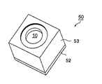
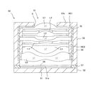
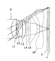
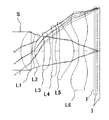
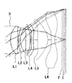
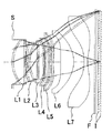
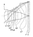
以下、本発明の実施の形態を図面に基づいて説明する。図1は、本実施の形態にかかる撮像ユニット(撮像装置)50の斜視図であり、図2は、撮像ユニット50の撮像レンズの光軸に沿った断面を模式的に示した図である。
Hereinafter, embodiments of the present invention will be described with reference to the drawings. FIG. 1 is a perspective view of an imaging unit (imaging device) 50 according to the present embodiment, and FIG. 2 is a diagram schematically showing a cross section along the optical axis of the imaging lens of the
図2に示すように、撮像ユニット50は、光電変換部51aを有する固体撮像素子としてのCMOS型撮像素子51と、この撮像素子51の光電変換部51aに被写体像を撮像させる撮像レンズ10と、撮像レンズ10を保持する鏡筒53と、撮像レンズ10と撮像素子51の間に配置された平行平板状の光学フィルタ54と、撮像レンズ10の前群を駆動する第1アクチュエータ55と、撮像レンズ10の後群を駆動する第2アクチュエータ56と、撮像素子51を実装した基板52と、光学フィルタ54を保持しつつ鏡筒53と基板52とを連結する台座部材57とを有する。
As shown in FIG. 2, the
図2に示すように、撮像素子51は、その受光側の平面の中央部に、画素(光電変換素子)が2次元的に配置された、受光部としての光電変換部51aが形成されており、その周囲には信号処理回路(不図示)が形成されている。かかる信号処理回路は、各画素を順次駆動し信号電荷を得る駆動回路部と、各信号電荷をデジタル信号に変換するA/D変換部と、このデジタル信号を用いて画像信号出力を形成する信号処理部等から構成されている。また、撮像素子51の受光側の平面の外縁近傍には、多数のパッド(図示略)が配置されており、不図示のワイヤを介して基板52に接続されている。撮像素子51は、光電変換部51aからの信号電荷をデジタルYUV信号等の画像信号等に変換し、ワイヤを介して基板52上の所定の回路に出力する。ここで、Yは輝度信号、U(=R−Y)は赤と輝度信号との色差信号、V(=B−Y)は青と輝度信号との色差信号である。なお、撮像素子は上記CMOS型のイメージセンサに限定されるものではなく、CCD等の他のものを使用しても良い。
As shown in FIG. 2, the
鏡筒53の物体側に、小開口(ここでは開口絞り)Sが設けられた物体側壁53aが形成されている。
On the object side of the
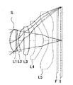
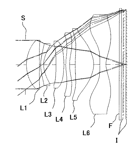
鏡筒53内に配置された撮像レンズ10は、物体側より順に、正の屈折力を有する第1レンズL1(ここではレンズA)、負の屈折力を有する第2レンズL2(ここではレンズB)、第3レンズL3、第4レンズL4、第5レンズL5,像側面が有効径内に極値を持つ第6レンズL6(ここではレンズC)からなる。前群を構成するレンズL1〜L3は、フランジ部を第1ホルダHD1により保持されており、第1アクチュエータ55により光軸方向に移動可能とされている。又、後群を構成するレンズL4〜L6は、フランジ部を第2ホルダHD2により保持されており、第2アクチュエータ56により光軸方向に移動可能とされている。撮像レンズ10は、遠距離被写体の撮影時に対して、近距離被写体の撮影時に、前群と後群が、以下の条件式を満足するように光軸方向物体側と移動する。
1.00<MF/MR<1.80 (1)
但し
MF:前群の位置変化量(mm)
MR:後群の位置変化量(mm)
The
1.00 <MF / MR <1.80 (1)
However, MF: Position change amount of front group (mm)
MR: Rear group position change (mm)
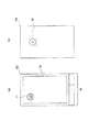
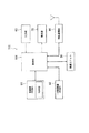
上述した撮像ユニット50の動作について説明する。図3は、撮像ユニット50を携帯端末としてのスマートフォン100に装備した状態を示す図である。また、図4はスマートフォン100の制御ブロック図である。
The operation of the
撮像ユニット50は、例えば、鏡筒53の物体側端面がスマートフォン100の背面(図3(b)参照)に設けられ、タッチパネル70の裏側に相当する位置に配設される。
In the
撮像ユニット50は、スマートフォン100の制御部101と接続され、輝度信号や色差信号等の画像信号を制御部101側に出力する。
The
一方、スマートフォン100は、図4に示すように、各部を統括的に制御すると共に、各処理に応じたプログラムを実行する制御部(CPU)101と、番号等をキーにより指示入力するための入力部60と、所定のデータの他に撮像した映像等を表示する液晶表示部70と、外部サーバとの間の各種情報通信を実現するための無線通信部80と、スマートフォン100のシステムプログラムや各種処理プログラム及び端末ID等の必要な諸データを記憶している記憶部(ROM)91と、制御部101によって実行される各種処理プログラムやデータ、若しくは処理データ、或いは撮像ユニット50により得られた撮像データ等を一時的に格納する作業領域として用いられる及び一時記憶部(RAM)92とを備えている。
On the other hand, as shown in FIG. 4, the
スマートフォン100は、入力キー部60の操作によって動作し、タッチパネル(表示部)70に表示されたアイコン71等をタッチすることで、撮像ユニット50を動作させて撮像を行うことができる。このとき、アクチュエータ55、56を駆動することで、無限遠方から近距離被写体までフォーカシングを行うことができる。撮像ユニット50から入力された画像信号は、制御部101で後述する画像処理を施され、上記スマートフォン100の制御系により、記憶部92に記憶されたり、或いはタッチパネル70で表示され、さらには、無線通信部80を介して映像情報として外部に送信される。
The
(実施例)
次に、上述した実施の形態に好適な実施例について説明する。但し、以下に示す実施例により本発明が限定されるものではない。実施例における各符号の意味は以下の通りである(長さの単位は、波長以外mm)。
FL:撮像レンズ全系の焦点距離(mm)
Fno:Fナンバー
w :半画角(゜)
Ymax:固体撮像素子の撮像面対角線長の半分の長さ(最大像高:mm)
BF:バックフォーカス(mm)(撮像レンズ全系の最も物体側のレンズ面から像面までの光軸上の距離)
TL:光学全長(mm)
BFa:バックフォーカス(mm)(撮像レンズ全系の最も物体側のレンズ面から像面までの距離。但し、カバーガラスを空気換算長とした場合の近軸像面までの光軸上の距離)
TLa:光学全長(mm)(撮像レンズ全系の最も物体側のレンズ面から像面までの光軸上の距離。但し、カバーガラスを空気換算長とした場合の近軸像面までの光軸上の距離)
r :屈折面の曲率半径(mm)
d :軸上面間隔(mm)
nd:レンズ材料のd線の常温での屈折率
vd:レンズ材料のアッベ数
STO:開口絞り
(Example)
Next, examples suitable for the above-described embodiment will be described. However, the present invention is not limited to the following examples. The meaning of each code | symbol in an Example is as follows (a unit of length is mm other than a wavelength).
FL: Focal length of the entire imaging lens system (mm)
Fno: F number w: Half angle of view (°)
Ymax: half the diagonal length of the imaging surface of the solid-state imaging device (maximum image height: mm)
BF: Back focus (mm) (distance on the optical axis from the lens surface closest to the object side to the image plane in the entire imaging lens system)
TL: Optical total length (mm)
BFa: Back focus (mm) (distance from the lens surface closest to the object side of the entire imaging lens system to the image plane. However, the distance on the optical axis to the paraxial image plane when the cover glass is an air conversion length)
TLa: optical total length (mm) (distance on the optical axis from the lens surface closest to the object side of the entire imaging lens system to the image plane. However, the optical axis to the paraxial image plane when the cover glass is an air-converted length. Distance above)
r: radius of curvature of refractive surface (mm)
d: Distance between shaft upper surfaces (mm)
nd: Refractive index of lens material at d-line at room temperature vd: Abbe number of lens material STO: Aperture stop
各実施例において、各面番号の後に「*」が記載されている面が非球面形状を有する面であり、非球面の形状は、面の頂点を原点とし、光軸方向にX軸をとり、光軸と垂直方向の高さをhとして以下の「数1」で表す。
In each embodiment, the surface described with “*” after each surface number is a surface having an aspheric shape, and the shape of the aspheric surface has the vertex of the surface as the origin and the X axis in the optical axis direction. The height in the direction perpendicular to the optical axis is h, and is expressed by the following “
Ai:i次の非球面係数
R :曲率半径
K :円錐定数
である。
Ai: i-th order aspherical coefficient R: radius of curvature K: conic constant.
また、以降(表のレンズデータを含む)において、10のべき乗数(例えば、2.5×10-02)を、E(例えば2.5e−002)を用いて表すものとする。また、レンズデータの面番号は第1レンズの物体側を1面として順に付与した。なお、実施例に記載の長さを表す数値の単位はすべてmmとする。 In the following (including the lens data in the table), a power of 10 (for example, 2.5 × 10 −02 ) is expressed using E (for example, 2.5e−002). The surface number of the lens data was given in order with the object side of the first lens as one surface. In addition, the unit of the numerical value showing the length as described in an Example shall be mm.
なお、請求項ならびに実施例に記載の近軸曲率半径の意味合いについて、実際のレンズ測定の場面においては、レンズ中央近傍(具体的には、レンズ有効径に対して10%以内の中央領域)での形状測定値を最小自乗法でフィッティングした際の近似曲率半径を近軸曲率半径であるとみなすことができる。また、例えば2次の非球面係数を使用した場合には、非球面定義式の基準曲率半径に2次の非球面係数も勘案した曲率半径を近軸曲率半径とみなすことができる。(例えば参考文献として、松居吉哉著「レンズ設計法」(共立出版株式会社)のP41〜42を参照のこと) In addition, regarding the implication of the paraxial radius of curvature described in the claims and examples, in the actual lens measurement scene, in the vicinity of the center of the lens (specifically, the central region within 10% of the lens effective diameter). The approximate radius of curvature when the measured shape of the shape is fitted by the method of least squares can be regarded as the paraxial radius of curvature. For example, when a secondary aspherical coefficient is used, a radius of curvature that takes into account the secondary aspherical coefficient in the reference curvature radius of the aspherical definition formula can be regarded as a paraxial curvature radius. (For example, see references 41 to 42 of Yoshiya Matsui's “Lens Design Method” (Kyoritsu Publishing Co., Ltd.) for reference)
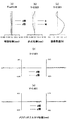
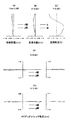
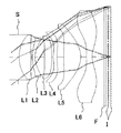
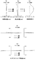
(実施例1と比較例1)
実施例1及び比較例1におけるレンズデータを表1に示す。図5は実施例1のレンズの断面図であり、図6は、比較例1のレンズの断面図である。実施例1及び比較例1とは、レンズ形状は共通であり、無限遠方にフォーカシングした際のレンズ位置も共通である。但し、近距離被写体にフォーカシングした際に、実施例1は前群と後群の繰り出し量が異なり、比較例1は全群の繰り出し量が等しくなっている。図5、6において、実線は近距離被写体(撮像レンズから10cm)フォーカシング時のレンズ位置と撮像面位置と光路を示し、一点鎖線は無限遠方フォーカシング時のレンズ位置と撮像面位置と光路を示している。なお、比較しやすいように、図5,6においては、撮像レンズ側(図5ではレンズL4〜L6)を固定し、相対的に撮像面が移動したものとして示している。
(Example 1 and Comparative Example 1)
Table 1 shows lens data in Example 1 and Comparative Example 1. FIG. 5 is a cross-sectional view of the lens of Example 1, and FIG. 6 is a cross-sectional view of the lens of Comparative Example 1. The lens shape is the same as in Example 1 and Comparative Example 1, and the lens position when focusing to infinity is also common. However, when focusing on a short-distance subject, Example 1 differs in the amount of extension of the front group and the rear group, and Comparative Example 1 has the same amount of extension for all groups. 5 and 6, the solid line indicates the lens position, the imaging surface position, and the optical path when focusing on a short-distance subject (10 cm from the imaging lens), and the alternate long and short dash line indicates the lens position, imaging surface position, and optical path when focusing on infinity. Yes. For easy comparison, FIGS. 5 and 6 show that the imaging lens side (lenses L4 to L6 in FIG. 5) is fixed and the imaging surface is relatively moved.
実施例1及び比較例1の撮像レンズは、物体側から順に、開口絞りS,正の屈折力を有する第1レンズL1(レンズA)、負の屈折力を有する第2レンズL2(レンズB)、第3レンズL3、第4レンズL4,第5レンズL5,像側面が有効径内に極値を持つ第6レンズL6(レンズC)からなる。第1レンズL1の正の屈折力は、前群中、最も強いものであり、第6レンズL6は、光軸付近に負の屈折力を持ち、周辺に正の屈折力を持つ。Fはカバーガラス又はIRカットフィルタを想定した平行平板であり、Iは固体撮像素子の撮像面である。実施例1では、レンズL1〜L3が前群を構成し、レンズL4〜L6が後群を構成する。 The imaging lenses of Example 1 and Comparative Example 1 have an aperture stop S, a first lens L1 having a positive refractive power (lens A), and a second lens L2 having a negative refractive power (lens B) in order from the object side. The third lens L3, the fourth lens L4, the fifth lens L5, and the sixth lens L6 (lens C) whose image side surface has an extreme value within the effective diameter. The positive refractive power of the first lens L1 is the strongest in the front group, and the sixth lens L6 has a negative refractive power in the vicinity of the optical axis and a positive refractive power in the periphery. F is a parallel plate assuming a cover glass or an IR cut filter, and I is an imaging surface of the solid-state imaging device. In Example 1, the lenses L1 to L3 constitute the front group, and the lenses L4 to L6 constitute the rear group.
[表1]
[実施例1]
Reference Wave Length = 587.56 nm
面データ
面番号 r d nd vd 有効径
STO INFINITY 0.0500 2.700
2* 2.0164 0.7001 1.54470 56.2 2.625
3* -9.8401 0.0681 2.489
4* 1.9159 0.1548 1.63469 23.9 2.263
5* 1.1239 0.4595 2.046
6 INFINITY 0.2000 2.002
7* -20.2537 0.4142 1.54470 56.2 2.203
8* -6.3415 VARIABLE 2.532
9* 2.4936 0.2000 1.63469 23.9 3.088
10* 1.9276 0.3004 3.406
11* 7.8447 0.9846 1.54470 56.2 3.597
12* -1.3875 0.3194 3.847
13* 7.4959 0.3225 1.54470 56.2 5.062
14* 1.0490 0.7000 5.336
15 INFINITY 0.1100 1.51633 64.1 6.000
16 INFINITY VARIABLE 6.000
非球面係数
2:K=5.34931e-001,A4=-1.69769e-003,A6=1.63552e-003,A8=-1.19855e-002,A10=1.49150e-002,A12=-8.23861e-003,A14=1.86134e-003
3:K=-7.50627e+001,A4=9.15739e-002,A6=-1.12007e-001,A8=1.14533e-001,A10=-7.65568e-002,A12=2.95866e-002,A14=-4.87500e-003
4:K=-1.59992e+001,A4=1.39545e-002,A6=-3.81141e-002,A8=5.61809e-002,A10=-4.79593e-002,A12=1.90519e-002,A14=-3.54001e-003
5:K=-4.86945e+000,A3=-1.12825e-002,A4=1.09747e-002,A5=2.78450e-002,A6=4.62375e-002,A8=-1.16515e-001,A10=1.49399e-001,A12=-1.01912e-001,A14=2.83205e-002
7:K=-4.82385e+001,A3=-1.07910e-002,A4=4.07725e-002,A5=-1.40323e-001,A6=1.33801e-001,A8=-1.67791e-001,A10=1.83451e-001,A12=-1.11716e-001,A14=2.51870e-002
8:K=-8.00000e+001,A3=-2.10832e-002,A4=-6.64680e-002,A5=9.42365e-002,A6=-1.18450e-001,A8=3.68282e-002,A10=-8.95217e-004,A12=-5.41019e-003
9:K=1.32838e-001,A3=-1.75807e-002,A4=-3.09421e-001,A5=3.68096e-001,A6=-2.67632e-001,A8=9.92310e-002,A10=-2.69240e-002,A12=2.68515e-003
10:K=5.46443e-002,A3=-2.69423e-002,A4=-2.49595e-001,A5=1.56177e-001,A6=-5.38703e-002,A8=1.57095e-003,A10=6.10817e-003,A12=-2.46515e-003,A14=2.16168e-004
11:K=-5.85358e+001,A3=-2.30635e-002,A4=8.25686e-002,A5=-1.48628e-001,A6=9.27047e-002,A8=-3.86835e-002,A10=1.64803e-002,A12=-3.56651e-003,A14=3.08117e-004
12:K=-8.00463e+000,A3=-6.22701e-002,A4=-8.42285e-002,A5=8.55637e-002,A6=-1.52955e-002,A8=-1.44000e-002,A10=7.06880e-003,A12=-1.15541e-003,A14=5.92561e-005
13:K=5.78031e+000,A3=-1.64712e-001,A4=-9.25534e-002,A5=4.02699e-002,A6=2.35776e-002,A8=-2.78645e-003,A10=-3.66823e-004,A12=8.01289e-005,A14=-4.00882e-006
14:K=-5.94778e+000,A3=-3.08084e-002,A4=-1.18894e-001,A5=9.88842e-002,A6=-2.71705e-002,A8=9.54064e-004,A10=-1.17795e-004,A12=2.49313e-005,A14=-1.55834e-006
FL 3.784
Fno 1.44
w 75.43
Ymax 2.921
BF 0.909
TL 5.183
BFa 0.872
TLa 5.145
合焦距離 INF 10cm 10cm全群繰出し(比較例)
d8 0.1000 0.1451 0.1000
d16 0.0992 0.2196 0.2459
Elem Surfs Focal Length Diameter
1 2- 3 3.1376 2.625
2 4- 5 -4.6355 2.263
3 7- 8 16.7730 2.532
4 9-10 -15.5096 3.406
5 11-12 2.2490 3.847
6 13-14 -2.2794 5.336
[table 1]
[Example 1]
Reference Wave Length = 587.56 nm
Surface data surface number rd nd vd Effective diameter
STO INFINITY 0.0500 2.700
2 * 2.0164 0.7001 1.54470 56.2 2.625
3 * -9.8401 0.0681 2.489
4 * 1.9159 0.1548 1.63469 23.9 2.263
5 * 1.1239 0.4595 2.046
6 INFINITY 0.2000 2.002
7 * -20.2537 0.4142 1.54470 56.2 2.203
8 * -6.3415 VARIABLE 2.532
9 * 2.4936 0.2000 1.63469 23.9 3.088
10 * 1.9276 0.3004 3.406
11 * 7.8447 0.9846 1.54470 56.2 3.597
12 * -1.3875 0.3194 3.847
13 * 7.4959 0.3225 1.54470 56.2 5.062
14 * 1.0490 0.7000 5.336
15 INFINITY 0.1100 1.51633 64.1 6.000
16 INFINITY VARIABLE 6.000
Aspheric coefficient
2: K = 5.34931e-001, A4 = -1.69769e-003, A6 = 1.63552e-003, A8 = -1.19855e-002, A10 = 1.49150e-002, A12 = -8.23861e-003, A14 = 1.86134 e-003
3: K = -7.50627e + 001, A4 = 9.15739e-002, A6 = -1.12007e-001, A8 = 1.14533e-001, A10 = -7.65568e-002, A12 = 2.95866e-002, A14 =- 4.87500e-003
4: K = -1.59992e + 001, A4 = 1.39545e-002, A6 = -3.81141e-002, A8 = 5.61809e-002, A10 = -4.79593e-002, A12 = 1.90519e-002, A14 =- 3.54001e-003
5: K = -4.86945e + 000, A3 = -1.12825e-002, A4 = 1.09747e-002, A5 = 2.78450e-002, A6 = 4.62375e-002, A8 = -1.16515e-001, A10 = 1.49399 e-001, A12 = -1.01912e-001, A14 = 2.83205e-002
7: K = -4.82385e + 001, A3 = -1.07910e-002, A4 = 4.07725e-002, A5 = -1.40323e-001, A6 = 1.33801e-001, A8 = -1.67791e-001, A10 = 1.83451e-001, A12 = -1.11716e-001, A14 = 2.51870e-002
8: K = -8.00000e + 001, A3 = -2.10832e-002, A4 = -6.64680e-002, A5 = 9.42365e-002, A6 = -1.18450e-001, A8 = 3.68282e-002, A10 = -8.95217e-004, A12 = -5.41019e-003
9: K = 1.32838e-001, A3 = -1.75807e-002, A4 = -3.09421e-001, A5 = 3.68096e-001, A6 = -2.67632e-001, A8 = 9.92310e-002, A10 =- 2.69240e-002, A12 = 2.68515e-003
10: K = 5.46443e-002, A3 = -2.69423e-002, A4 = -2.49595e-001, A5 = 1.56177e-001, A6 = -5.38703e-002, A8 = 1.57095e-003, A10 = 6.10817 e-003, A12 = -2.46515e-003, A14 = 2.16168e-004
11: K = -5.85358e + 001, A3 = -2.30635e-002, A4 = 8.25686e-002, A5 = -1.48628e-001, A6 = 9.27047e-002, A8 = -3.86835e-002, A10 = 1.64803e-002, A12 = -3.56651e-003, A14 = 3.08117e-004
12: K = -8.00463e + 000, A3 = -6.22701e-002, A4 = -8.42285e-002, A5 = 8.55637e-002, A6 = -1.52955e-002, A8 = -1.44000e-002, A10 = 7.06880e-003, A12 = -1.15541e-003, A14 = 5.92561e-005
13: K = 5.78031e + 000, A3 = -1.64712e-001, A4 = -9.25534e-002, A5 = 4.02699e-002, A6 = 2.35776e-002, A8 = -2.78645e-003, A10 =- 3.66823e-004, A12 = 8.01289e-005, A14 = -4.00882e-006
14: K = -5.94778e + 000, A3 = -3.08084e-002, A4 = -1.18894e-001, A5 = 9.88842e-002, A6 = -2.71705e-002, A8 = 9.54064e-004, A10 = -1.17795e-004, A12 = 2.49313e-005, A14 = -1.55834e-006
FL 3.784
Fno 1.44
w 75.43
Ymax 2.921
BF 0.909
TL 5.183
BFa 0.872
TLa 5.145
Focusing distance INF 10cm 10cm all groups extended (comparative example)
d8 0.1000 0.1451 0.1000
d16 0.0992 0.2196 0.2459
Elem Surfs Focal Length Diameter
1 2- 3 3.1376 2.625
2 4- 5 -4.6355 2.263
3 7-8 16.7730 2.532
4 9-10 -15.5096 3.406
5 11-12 2.2490 3.847
6 13-14 -2.2794 5.336
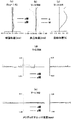
図7は実施例1及び比較例1の無限遠方フォーカシング時の収差図(球面収差(a)、非点収差(b)、歪曲収差(c)、メリディオナルコマ収差(d),(e))である。図8は実施例1の近距離被写体フォーカシング時の収差図(球面収差(a)、非点収差(b)、歪曲収差(c)、メリディオナルコマ収差(d),(e))である。図9は比較例1の近距離被写体フォーカシング時の収差図(球面収差(a)、非点収差(b)、歪曲収差(c)、メリディオナルコマ収差(d),(e))である。ここで、球面収差図及びメリディオナルコマ収差図において、実線はd線、点線はg線に対する球面収差量をそれぞれ表し、非点収差図において、実線Sはサジタル面、点線Mはメリディオナル面を表す(以下、同じ)。 FIG. 7 is an aberration diagram at the time of infinity focusing in Example 1 and Comparative Example 1 (spherical aberration (a), astigmatism (b), distortion (c), meridional coma (d), (e). ). FIG. 8 is an aberration diagram (spherical aberration (a), astigmatism (b), distortion aberration (c), meridional coma aberration (d), (e)) at the time of focusing on a short distance object in Example 1. . FIG. 9 is an aberration diagram (spherical aberration (a), astigmatism (b), distortion aberration (c), meridional coma aberration (d), (e)) at the time of short-distance object focusing in Comparative Example 1. . Here, in the spherical aberration diagram and the meridional coma aberration diagram, the solid line represents the amount of spherical aberration with respect to the d-line and the dotted line, respectively, and in the astigmatism diagram, the solid line S represents the sagittal surface and the dotted line M represents the meridional surface. Represent (hereinafter the same).
図5,6を比較すると、全群等量繰出しの比較例1に対して、後群より前群の繰り出し量を大きくした実施例1では、無限遠方フォーカシング時の光路(実線)に対して、近距離被写体フォーカシング時の光路(一点鎖線)の光軸直交方向変動量が少ない。よって、各レンズの光線入射位置の変動が、被写体距離にかかわらず抑制される。これにより、図8,9を比較すると明らかなように、収差変動を抑制できる。 Comparing FIGS. 5 and 6, in Example 1 in which the feeding amount of the front group is larger than that of the rear group compared to Comparative Example 1 in which all groups are fed out, the optical path (solid line) during infinitely far focusing is The amount of fluctuation in the direction perpendicular to the optical axis of the optical path (one-dot chain line) during short-distance subject focusing is small. Therefore, fluctuations in the light incident position of each lens are suppressed regardless of the subject distance. As a result, as is apparent from a comparison between FIGS.
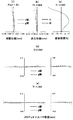
(実施例2と比較例2)
実施例2及び比較例2におけるレンズデータを表2に示す。図10は実施例2のレンズの断面図であり、図11は、比較例2のレンズの断面図である。実施例2及び比較例2とは、レンズ形状は共通であり、無限遠方にフォーカシングした際のレンズ位置も共通である。但し、近距離被写体にフォーカシングした際に、実施例2は前群と後群の繰り出し量が異なり、比較例2は全群の繰り出し量が等しくなっている。図10、11において、実線は近距離被写体(撮像レンズから10cm)フォーカシング時のレンズ位置と撮像面位置と光路を示し、一点鎖線は無限遠方フォーカシング時のレンズ位置と撮像面位置と光路を示している。なお、比較しやすいように、図10,11においては、撮像レンズ側(図10ではレンズL5〜L6)を固定し、相対的に撮像面が移動したものとして示している。
(Example 2 and Comparative Example 2)
Table 2 shows lens data in Example 2 and Comparative Example 2. 10 is a cross-sectional view of the lens of Example 2, and FIG. 11 is a cross-sectional view of the lens of Comparative Example 2. In Example 2 and Comparative Example 2, the lens shape is common, and the lens position when focusing to infinity is also common. However, when focusing on a short-distance subject, the amount of extension in the front group and the rear group is different in Example 2, and the amount of extension in all groups is equal in Comparative Example 2. 10 and 11, the solid line indicates the lens position, the imaging surface position, and the optical path when focusing on a short-distance subject (10 cm from the imaging lens), and the alternate long and short dash line indicates the lens position, imaging surface position, and optical path when focusing on infinity. Yes. For easy comparison, in FIGS. 10 and 11, the imaging lens side (lenses L5 to L6 in FIG. 10) is fixed and the imaging surface is relatively moved.
実施例2及び比較例2の撮像レンズは、物体側から順に、開口絞りS,正の屈折力を有する第1レンズL1(レンズA)、負の屈折力を有する第2レンズL2(レンズB)、第3レンズL3、第4レンズL4,第5レンズL5,像側面が有効径内に極値を持つ第6レンズL6(レンズC)からなる。第1レンズL1の正の屈折力は、前群中、最も強いものであり、第6レンズL6は、光軸付近に負の屈折力を持ち、周辺に正の屈折力を持つ。Fはカバーガラス又はIRカットフィルタを想定した平行平板であり、Iは固体撮像素子の撮像面である。実施例2では、レンズL1〜L4が前群を構成し、レンズL5〜L6が後群を構成する。 The imaging lenses of Example 2 and Comparative Example 2 have an aperture stop S, a first lens L1 having a positive refractive power (lens A), and a second lens L2 having a negative refractive power (lens B) in order from the object side. The third lens L3, the fourth lens L4, the fifth lens L5, and the sixth lens L6 (lens C) whose image side surface has an extreme value within the effective diameter. The positive refractive power of the first lens L1 is the strongest in the front group, and the sixth lens L6 has a negative refractive power in the vicinity of the optical axis and a positive refractive power in the periphery. F is a parallel plate assuming a cover glass or an IR cut filter, and I is an imaging surface of the solid-state imaging device. In Example 2, the lenses L1 to L4 constitute the front group, and the lenses L5 to L6 constitute the rear group.
[表2]
[実施例2]
面データ
面番号 r d nd vd 有効径
STO INFINITY 0.0500 2.625
2* 2.0091 0.6952 1.54470 56.2 2.640
3* -10.4799 0.0740 2.512
4* 1.9937 0.1542 1.63469 23.9 2.291
5* 1.1620 0.4005 2.074
6 INFINITY 0.1400 2.129
7* 4208.7895 0.4097 1.54470 56.2 2.244
8* -56.7294 0.1000 2.490
9* 2.5035 0.2000 1.63469 23.9 2.625
10* 2.3858 VARIABLE 2.943
11* 12.6375 0.9737 1.54470 56.2 3.367
12* -1.3092 0.3286 3.814
13* 8.3099 0.3223 1.54470 56.2 5.126
14* 1.0423 0.7000 5.375
15 INFINITY 0.1100 1.51633 64.1 5.763
16 INFINITY VARIABLE 5.810
非球面係数
2:K=1.57279e-001,A4=3.94752e-003,A6=2.83183e-003,A8=-9.37735e-003,A10=1.29937e-002,A12=-7.46045e-003,A14=1.83372e-003
3:K=-5.50362e+001,A4=9.45062e-002,A6=-1.13062e-001,A8=1.15232e-001,A10=-7.80785e-002,A12=3.06439e-002,A14=-5.06147e-003
4:K=-1.69116e+001,A4=1.64439e-002,A6=-3.75357e-002,A8=5.35850e-002,A10=-4.41587e-002,A12=1.82114e-002,A14=-3.54001e-003
5:K=-5.56093e+000,A3=6.26744e-004,A4=2.34287e-002,A5=1.53577e-002,A6=3.01794e-002,A8=-1.01448e-001,A10=1.55943e-001,A12=-1.15852e-001,A14=3.41357e-002
7:K=8.00000e+001,A3=-1.63174e-002,A4=6.28962e-002,A5=-1.50417e-001,A6=1.34480e-001,A8=-1.60432e-001,A10=1.78874e-001,A12=-1.14292e-001,A14=2.61146e-002
8:K=8.00000e+001,A3=-8.56030e-002,A4=-1.93295e-002,A5=8.80337e-002,A6=-1.29806e-001,A8=2.75352e-002,A10=3.20224e-003,A12=-6.07380e-003
9:K=-3.39979e+000,A3=-7.07642e-002,A4=-3.45283e-001,A5=3.77120e-001,A6=-2.87979e-001,A8=8.54697e-002,A10=-2.20272e-002,A12=5.44002e-003
10:K=1.26619e+000,A3=-3.55406e-002,A4=-2.77981e-001,A5=1.26735e-001,A6=-5.06670e-002,A8=3.83498e-003,A10=4.81753e-003,A12=-2.53396e-003,A14=2.04537e-004
11:K=-8.00000e+001,A3=-1.80134e-002,A4=5.24632e-002,A5=-1.07760e-001,A6=7.59798e-002,A8=-4.05601e-002,A10=1.80609e-002,A12=-4.19070e-003,A14=3.13615e-004
12:K=-7.51540e+000,A3=-7.10944e-002,A4=-8.92430e-002,A5=9.31586e-002,A6=-1.36116e-002,A8=-1.59368e-002,A10=7.09451e-003,A12=-1.07278e-003,A14=3.14152e-005
13:K=7.73185e+000,A3=-1.55686e-001,A4=-9.05406e-002,A5=3.86140e-002,A6=2.28519e-002,A8=-2.77300e-003,A10=-3.55190e-004,A12=8.08088e-005,A14=-4.15519e-006
14:K=-6.01675e+000,A3=-1.64177e-002,A4=-1.32244e-001,A5=1.01778e-001,A6=-2.65959e-002,A8=8.39264e-004,A10=-1.30386e-004,A12=2.55692e-005,A14=-1.40288e-006
FL 3.778
Fno 1.44
w 75.42
Ymax 2.921
BF 0.914
TL 5.172
BFa 0.877
TLa 5.135
合焦距離 INF 10cm 10cm全群繰出し(比較例)
d10 0.4099 0.4514 0.4099
d16 0.1043 0.2386 0.2495
Elem Surfs Focal Length Diameter
1 2- 3 3.1570 2.640
2 4- 5 -4.7290 2.291
3 7- 8 102.7664 2.490
4 9-10 -234.7668 2.943
5 11-12 2.2329 3.814
6 13-14 -2.2227 5.375
[Table 2]
[Example 2]
Surface data surface number rd nd vd Effective diameter
STO INFINITY 0.0500 2.625
2 * 2.0091 0.6952 1.54470 56.2 2.640
3 * -10.4799 0.0740 2.512
4 * 1.9937 0.1542 1.63469 23.9 2.291
5 * 1.1620 0.4005 2.074
6 INFINITY 0.1400 2.129
7 * 4208.7895 0.4097 1.54470 56.2 2.244
8 * -56.7294 0.1000 2.490
9 * 2.5035 0.2000 1.63469 23.9 2.625
10 * 2.3858 VARIABLE 2.943
11 * 12.6375 0.9737 1.54470 56.2 3.367
12 * -1.3092 0.3286 3.814
13 * 8.3099 0.3223 1.54470 56.2 5.126
14 * 1.0423 0.7000 5.375
15 INFINITY 0.1100 1.51633 64.1 5.763
16 INFINITY VARIABLE 5.810
Aspheric coefficient
2: K = 1.57279e-001, A4 = 3.94752e-003, A6 = 2.83183e-003, A8 = -9.37735e-003, A10 = 1.29937e-002, A12 = -7.46045e-003, A14 = 1.83372e -003
3: K = -5.50362e + 001, A4 = 9.45062e-002, A6 = -1.13062e-001, A8 = 1.15232e-001, A10 = -7.80785e-002, A12 = 3.06439e-002, A14 =- 5.06147e-003
4: K = -1.69116e + 001, A4 = 1.64439e-002, A6 = -3.75357e-002, A8 = 5.35850e-002, A10 = -4.41587e-002, A12 = 1.82114e-002, A14 =- 3.54001e-003
5: K = -5.56093e + 000, A3 = 6.26744e-004, A4 = 2.34287e-002, A5 = 1.53577e-002, A6 = 3.01794e-002, A8 = -1.01448e-001, A10 = 1.55943e -001, A12 = -1.15852e-001, A14 = 3.41357e-002
7: K = 8.00000e + 001, A3 = -1.63174e-002, A4 = 6.28962e-002, A5 = -1.50417e-001, A6 = 1.34480e-001, A8 = -1.60432e-001, A10 = 1.78874 e-001, A12 = -1.14292e-001, A14 = 2.61146e-002
8: K = 8.00000e + 001, A3 = -8.56030e-002, A4 = -1.93295e-002, A5 = 8.80337e-002, A6 = -1.29806e-001, A8 = 2.75352e-002, A10 = 3.20224 e-003, A12 = -6.07380e-003
9: K = -3.39979e + 000, A3 = -7.07642e-002, A4 = -3.45283e-001, A5 = 3.77120e-001, A6 = -2.87979e-001, A8 = 8.54697e-002, A10 = -2.20272e-002, A12 = 5.44002e-003
10: K = 1.26619e + 000, A3 = -3.55406e-002, A4 = -2.77981e-001, A5 = 1.26735e-001, A6 = -5.06670e-002, A8 = 3.83498e-003, A10 = 4.81753 e-003, A12 = -2.53396e-003, A14 = 2.04537e-004
11: K = -8.00000e + 001, A3 = -1.80134e-002, A4 = 5.24632e-002, A5 = -1.07760e-001, A6 = 7.59798e-002, A8 = -4.05601e-002, A10 = 1.80609e-002, A12 = -4.19070e-003, A14 = 3.13615e-004
12: K = -7.51540e + 000, A3 = -7.10944e-002, A4 = -8.92430e-002, A5 = 9.31586e-002, A6 = -1.36116e-002, A8 = -1.59368e-002, A10 = 7.09451e-003, A12 = -1.07278e-003, A14 = 3.14152e-005
13: K = 7.73185e + 000, A3 = -1.55686e-001, A4 = -9.05406e-002, A5 = 3.86140e-002, A6 = 2.28519e-002, A8 = -2.77300e-003, A10 =- 3.55190e-004, A12 = 8.08088e-005, A14 = -4.15519e-006
14: K = -6.01675e + 000, A3 = -1.64177e-002, A4 = -1.32244e-001, A5 = 1.01778e-001, A6 = -2.65959e-002, A8 = 8.39264e-004, A10 = -1.30386e-004, A12 = 2.55692e-005, A14 = -1.40288e-006
FL 3.778
Fno 1.44
w 75.42
Ymax 2.921
BF 0.914
TL 5.172
BFa 0.877
TLa 5.135
Focusing distance INF 10cm 10cm all groups extended (comparative example)
d10 0.4099 0.4514 0.4099
d16 0.1043 0.2386 0.2495
Elem Surfs Focal Length Diameter
1 2- 3 3.1570 2.640
2 4- 5 -4.7290 2.291
3 7- 8 102.7664 2.490
4 9-10 -234.7668 2.943
5 11-12 2.2329 3.814
6 13-14 -2.2227 5.375
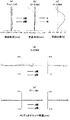
図12は実施例2及び比較例2の無限遠方フォーカシング時の収差図(球面収差(a)、非点収差(b)、歪曲収差(c)、メリディオナルコマ収差(d),(e))である。図13は実施例2の近距離被写体フォーカシング時の収差図(球面収差(a)、非点収差(b)、歪曲収差(c)、メリディオナルコマ収差(d),(e))である。図14は比較例2の近距離被写体フォーカシング時の収差図(球面収差(a)、非点収差(b)、歪曲収差(c)、メリディオナルコマ収差(d),(e))である。 FIG. 12 is an aberration diagram in Example 2 and Comparative Example 2 during focusing at infinity (spherical aberration (a), astigmatism (b), distortion (c), meridional coma (d), (e). ). FIG. 13 is an aberration diagram (spherical aberration (a), astigmatism (b), distortion aberration (c), meridional coma aberration (d), (e)) at the time of focusing on a short distance object in Example 2. . FIG. 14 is an aberration diagram (spherical aberration (a), astigmatism (b), distortion aberration (c), meridional coma aberration (d), (e)) at the time of short-distance object focusing in Comparative Example 2. .
図10,11を比較すると、全群等量繰出しの比較例2に対して、後群より前群の繰り出し量を大きくした実施例2では、無限遠方フォーカシング時の光路(実線)に対して、近距離被写体フォーカシング時の光路(一点鎖線)の光軸直交方向変動量が少ない。よって、各レンズの光線入射位置の変動が、被写体距離にかかわらず抑制される。これにより、図13,14を比較すると明らかなように、収差変動を抑制できる。 When comparing FIGS. 10 and 11, in Example 2 in which the feeding amount of the front group is larger than that of the rear group, compared to Comparative Example 2 in which all groups are fed out, the optical path (solid line) during infinitely far focusing is The amount of fluctuation in the direction perpendicular to the optical axis of the optical path (one-dot chain line) during short-distance subject focusing is small. Therefore, fluctuations in the light incident position of each lens are suppressed regardless of the subject distance. As a result, as is apparent from a comparison between FIGS.
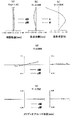
(実施例3と比較例3)
実施例3及び比較例3におけるレンズデータを表3に示す。図15は実施例3のレンズの断面図であり、図16は、比較例3のレンズの断面図である。実施例3及び比較例3とは、レンズ形状は共通であり、無限遠方にフォーカシングした際のレンズ位置も共通である。但し、近距離被写体にフォーカシングした際に、実施例3は前群と後群の繰り出し量が異なり、比較例3は全群の繰り出し量が等しくなっている。図15、16において、実線は近距離被写体(撮像レンズから10cm)フォーカシング時のレンズ位置と撮像面位置と光路を示し、一点鎖線は無限遠方フォーカシング時のレンズ位置と撮像面位置と光路を示している。なお、比較しやすいように、図15,16においては、撮像レンズ側(図15ではレンズL4〜L5)を固定し、相対的に撮像面が移動したものとして示している。
(Example 3 and Comparative Example 3)
Table 3 shows lens data in Example 3 and Comparative Example 3. 15 is a cross-sectional view of the lens of Example 3, and FIG. 16 is a cross-sectional view of the lens of Comparative Example 3. In Example 3 and Comparative Example 3, the lens shape is common, and the lens position when focusing to infinity is also common. However, when focusing on a short-distance subject, the amount of extension in the front group and the rear group is different in Example 3, and the amount of extension in all groups is equal in Comparative Example 3. 15 and 16, the solid line indicates the lens position, the imaging surface position, and the optical path when focusing on a short-distance subject (10 cm from the imaging lens), and the alternate long and short dash line indicates the lens position, imaging surface position, and optical path when focusing on infinity. Yes. For ease of comparison, in FIGS. 15 and 16, the imaging lens side (lenses L4 to L5 in FIG. 15) is fixed and the imaging surface is relatively moved.
実施例3及び比較例3の撮像レンズは、物体側から順に、開口絞りS,正の屈折力を有する第1レンズL1(レンズA)、負の屈折力を有する第2レンズL2(レンズB)、第3レンズL3、第4レンズL4,像側面が有効径内に極値を持つ第5レンズL5(レンズC)からなる。第1レンズL1の正の屈折力は、前群中、最も強いものであり、第5レンズL5は、光軸付近に負の屈折力を持ち、周辺に正の屈折力を持つ。Fはカバーガラス又はIRカットフィルタを想定した平行平板であり、Iは固体撮像素子の撮像面である。実施例3では、レンズL1〜L3が前群を構成し、レンズL4〜L5が後群を構成する。 The imaging lenses of Example 3 and Comparative Example 3 have an aperture stop S, a first lens L1 having a positive refractive power (lens A), and a second lens L2 having a negative refractive power (lens B) in order from the object side. The third lens L3, the fourth lens L4, and the fifth lens L5 (lens C) whose image side surface has an extreme value within the effective diameter. The positive refractive power of the first lens L1 is the strongest in the front group, and the fifth lens L5 has a negative refractive power in the vicinity of the optical axis and a positive refractive power in the periphery. F is a parallel plate assuming a cover glass or an IR cut filter, and I is an imaging surface of the solid-state imaging device. In Example 3, the lenses L1 to L3 constitute the front group, and the lenses L4 to L5 constitute the rear group.
[表3]
[実施例3]
面データ
面番号 r d nd vd 有効径
STO INFINITY 0.0500 1.966
2 INFINITY -0.3683 1.966
3* 1.5591 0.5338 1.54470 56.2 1.968
4* 33.4902 0.0778 1.862
5* 4.6119 0.1700 1.63469 23.9 1.864
6* 1.8613 0.4656 1.857
7* 8.9390 0.4826 1.54470 56.2 2.185
8* INFINITY VARIABLE 2.448
9* -17.0704 0.7113 1.54470 56.2 2.765
10* -1.2674 0.4855 3.361
11* -1.4052 0.3142 1.54470 56.2 4.761
12* 3.6294 0.4090 5.008
13 INFINITY 0.1100 1.51633 64.1 5.653
14 INFINITY VARIABLE 5.706
非球面係数
3:K=9.16290e-002,A4=2.03102e-003,A6=1.96915e-002,A8=-3.07399e-002,A10=2.63591e-000
4:K=-1.00000e+000,A4=-6.23278e-002,A6=2.39862e-001,A8=-3.66397e-001,A10=3.20886e-001,A12=-1.18037e-001
5:K=1.00000e+000,A4=-2.46567e-001,A6=5.69834e-001,A8=-7.16893e-001,A10=5.32203e-001,A12=-1.92818e-001
6:K=-2.27497e+001,A4=1.99084e-001,A6=-3.16574e-001,A8=6.64830e-001,A10=-6.33466e-001,A12=2.48060e-001
7:K=8.66996e+000,A4=-7.91911e-002,A6=-7.64850e-002,A8=2.73329e-001,A10=-4.46972e-001,A12=3.43230e-001,A14=-9.00657e-002
8:K=0.00000e+000,A4=-9.58045e-002,A6=5.96433e-002,A8=-1.34169e-001,A10=1.45786e-001,A12=-9.36522e-002,A14=2.77093e-002
9:K=1.00000e+000,A4=-8.88838e-002,A6=4.32356e-002,A8=-3.56913e-002,A10=1.35533e-002,A12=-4.27958e-003,
10:K=-3.09525e+000,A3=3.51468e-002,A4=-1.11481e-001,A5=1.44454e-002,A6=2.95663e-002,A8=2.84472e-003,A10=-2.85087e-003,A12=-1.56050e-005,A14=8.26462e-005
11:K=-1.03625e+000,A3=5.10144e-002,A4=7.28045e-003,A5=2.58949e-003,A6=2.03721e-003,A8=-2.00746e-004,A10=-2.56243e-005,A12=3.09141e-006,A14=1.52126e-008
12:K=-4.00000e+001,A3=3.23445e-003,A4=-2.08383e-002,A5=-1.42851e-003,A6=3.01963e-003,A8=-6.14877e-004,A10=-4.68535e-006,A12=4.94715e-006,A14=2.73261e-007
FL 3.719
Fno1.85
w 75.78
Ymax 2.921
BF 0.740
TL 4.500
BFa 0.703
TLa 4.462
合焦距離 INF 10cm 10cm全群繰出し(比較例)
d8 0.5190 0.5504 0.5190
d14 0.2210 0.3390 0.3640
Elem Surfs Focal Length Diameter
1 3- 4 2.9844 1.968
2 5- 6 -5.0380 1.864
3 7- 8 16.4109 2.448
4 9-10 2.4741 3.361
5 11-12 -1.8197 5.008
[Table 3]
[Example 3]
Surface data surface number rd nd vd Effective diameter
STO INFINITY 0.0500 1.966
2 INFINITY -0.3683 1.966
3 * 1.5591 0.5338 1.54470 56.2 1.968
4 * 33.4902 0.0778 1.862
5 * 4.6119 0.1700 1.63469 23.9 1.864
6 * 1.8613 0.4656 1.857
7 * 8.9390 0.4826 1.54470 56.2 2.185
8 * INFINITY VARIABLE 2.448
9 * -17.0704 0.7113 1.54470 56.2 2.765
10 * -1.2674 0.4855 3.361
11 * -1.4052 0.3142 1.54470 56.2 4.761
12 * 3.6294 0.4090 5.008
13 INFINITY 0.1100 1.51633 64.1 5.653
14 INFINITY VARIABLE 5.706
Aspheric coefficient
3: K = 9.16290e-002, A4 = 2.03102e-003, A6 = 1.96915e-002, A8 = -3.07399e-002, A10 = 2.63591e-000
4: K = -1.00000e + 000, A4 = -6.23278e-002, A6 = 2.39862e-001, A8 = -3.66397e-001, A10 = 3.20886e-001, A12 = -1.18037e-001
5: K = 1.00000e + 000, A4 = -2.46567e-001, A6 = 5.69834e-001, A8 = -7.16893e-001, A10 = 5.32203e-001, A12 = -1.92818e-001
6: K = -2.27497e + 001, A4 = 1.99084e-001, A6 = -3.16574e-001, A8 = 6.64830e-001, A10 = -6.33466e-001, A12 = 2.48060e-001
7: K = 8.66996e + 000, A4 = -7.91911e-002, A6 = -7.64850e-002, A8 = 2.73329e-001, A10 = -4.46972e-001, A12 = 3.43230e-001, A14 =- 9.00657e-002
8: K = 0.00000e + 000, A4 = -9.58045e-002, A6 = 5.96433e-002, A8 = -1.34169e-001, A10 = 1.45786e-001, A12 = -9.36522e-002, A14 = 2.77093 e-002
9: K = 1.00000e + 000, A4 = -8.88838e-002, A6 = 4.32356e-002, A8 = -3.56913e-002, A10 = 1.35533e-002, A12 = -4.27958e-003,
10: K = -3.09525e + 000, A3 = 3.51468e-002, A4 = -1.11481e-001, A5 = 1.44454e-002, A6 = 2.95663e-002, A8 = 2.84472e-003, A10 = -2.85087 e-003, A12 = -1.56050e-005, A14 = 8.26462e-005
11: K = -1.03625e + 000, A3 = 5.10144e-002, A4 = 7.28045e-003, A5 = 2.58949e-003, A6 = 2.03721e-003, A8 = -2.00746e-004, A10 = -2.56243 e-005, A12 = 3.09141e-006, A14 = 1.52126e-008
12: K = -4.00000e + 001, A3 = 3.23445e-003, A4 = -2.08383e-002, A5 = -1.42851e-003, A6 = 3.01963e-003, A8 = -6.14877e-004, A10 = -4.68535e-006, A12 = 4.94715e-006, A14 = 2.73261e-007
FL 3.719
Fno1.85
w 75.78
Ymax 2.921
BF 0.740
TL 4.500
BFa 0.703
TLa 4.462
Focusing distance INF 10cm 10cm all groups extended (comparative example)
d8 0.5190 0.5504 0.5190
d14 0.2210 0.3390 0.3640
Elem Surfs Focal Length Diameter
1 3- 4 2.9844 1.968
2 5- 6 -5.0380 1.864
3 7-8 16.4109 2.448
4 9-10 2.4741 3.361
5 11-12 -1.8197 5.008
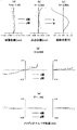
図17は実施例3及び比較例3の無限遠方フォーカシング時の収差図(球面収差(a)、非点収差(b)、歪曲収差(c)、メリディオナルコマ収差(d),(e))である。図18は実施例3の近距離被写体フォーカシング時の収差図(球面収差(a)、非点収差(b)、歪曲収差(c)、メリディオナルコマ収差(d),(e))である。図19は比較例3の近距離被写体フォーカシング時の収差図(球面収差(a)、非点収差(b)、歪曲収差(c)、メリディオナルコマ収差(d),(e))である。 FIG. 17 is an aberration diagram in Example 3 and Comparative Example 3 during focusing at infinity (spherical aberration (a), astigmatism (b), distortion (c), meridional coma (d), (e). ). FIG. 18 is an aberration diagram (spherical aberration (a), astigmatism (b), distortion aberration (c), meridional coma aberration (d), (e)) at the time of focusing on a short distance object in Example 3. . FIG. 19 is an aberration diagram (spherical aberration (a), astigmatism (b), distortion aberration (c), meridional coma aberration (d), (e)) at the time of short-distance object focusing in Comparative Example 3. .
図15,16を比較すると、全群等量繰出しの比較例3に対して、後群より前群の繰り出し量を大きくした実施例3では、無限遠方フォーカシング時の光路(実線)に対して、近距離被写体フォーカシング時の光路(一点鎖線)の光軸直交方向変動量が少ない。よって、各レンズの光線入射位置の変動が、被写体距離にかかわらず抑制される。これにより、図18,19を比較すると明らかなように、収差変動を抑制できる。 15 and 16, in Example 3 in which the amount of feeding of the front group is larger than that of the rear group, compared to Comparative Example 3 in which all the groups are fed out equally, with respect to the optical path (solid line) at infinity focusing, The amount of fluctuation in the direction perpendicular to the optical axis of the optical path (one-dot chain line) during short-distance subject focusing is small. Therefore, fluctuations in the light incident position of each lens are suppressed regardless of the subject distance. This makes it possible to suppress fluctuations in aberrations as is apparent when comparing FIGS.
(実施例4と比較例4)
実施例4及び比較例4におけるレンズデータを表4に示す。図20は実施例4のレンズの断面図であり、図21は、比較例4のレンズの断面図である。実施例4及び比較例4とは、レンズ形状は共通であり、無限遠方にフォーカシングした際のレンズ位置も共通である。但し、近距離被写体にフォーカシングした際に、実施例4は前群と後群の繰り出し量が異なり、比較例4は全群の繰り出し量が等しくなっている。図20、21において、実線は近距離被写体(撮像レンズから10cm)フォーカシング時のレンズ位置と撮像面位置と光路を示し、一点鎖線は無限遠方フォーカシング時のレンズ位置と撮像面位置と光路を示している。なお、比較しやすいように、図20,21においては、撮像レンズ側(図20ではレンズL4〜L7)を固定し、相対的に撮像面が移動したものとして示している。
(Example 4 and Comparative Example 4)
Table 4 shows lens data in Example 4 and Comparative Example 4. 20 is a cross-sectional view of the lens of Example 4, and FIG. 21 is a cross-sectional view of the lens of Comparative Example 4. The lens shape is the same as in Example 4 and Comparative Example 4, and the lens position when focusing to infinity is also common. However, when focusing on a short-distance subject, the amount of extension in the front group and the rear group is different in Example 4, and the amount of extension in all groups is equal in Comparative Example 4. 20 and 21, a solid line indicates a lens position, an imaging surface position, and an optical path at the time of focusing on a short-distance subject (10 cm from the imaging lens), and an alternate long and short dash line indicates a lens position, an imaging surface position, and an optical path at the time of infinity focusing. Yes. For easy comparison, in FIGS. 20 and 21, the imaging lens side (lenses L4 to L7 in FIG. 20) is fixed and the imaging surface is relatively moved.
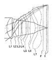
実施例4及び比較例4の撮像レンズは、物体側から順に、開口絞りS,正の屈折力を有する第1レンズL1(レンズA)、負の屈折力を有する第2レンズL2(レンズB)、第3レンズL3、第4レンズL4,第5レンズL5,第6レンズL6,像側面が有効径内に極値を持つ第7レンズL7(レンズC)からなる。第1レンズL1の正の屈折力は、前群中、最も強いものであり、第7レンズL7は、光軸付近に負の屈折力を持ち、周辺に正の屈折力を持つ。Fはカバーガラス又はIRカットフィルタを想定した平行平板であり、Iは固体撮像素子の撮像面である。実施例4では、レンズL1〜L3が前群を構成し、レンズL4〜L7が後群を構成する。 The imaging lenses of Example 4 and Comparative Example 4 have an aperture stop S, a first lens L1 having a positive refractive power (lens A), and a second lens L2 having a negative refractive power (lens B) in order from the object side. The third lens L3, the fourth lens L4, the fifth lens L5, the sixth lens L6, and the seventh lens L7 (lens C) whose image side surface has an extreme value within the effective diameter. The positive refractive power of the first lens L1 is the strongest in the front group, and the seventh lens L7 has a negative refractive power in the vicinity of the optical axis and a positive refractive power in the periphery. F is a parallel plate assuming a cover glass or an IR cut filter, and I is an imaging surface of the solid-state imaging device. In Example 4, the lenses L1 to L3 constitute the front group, and the lenses L4 to L7 constitute the rear group.
[表4]
[実施例4]
面データ
面番号 r d nd vd 有効径
STO INFINITY -0.2468 3.137
2* 2.5005 0.8252 1.54470 56.2 3.137
3* -10.5043 0.0718 2.988
4* 2.6081 0.2266 1.63469 23.9 2.737
5* 1.4393 0.5242 2.453
6 INFINITY 0.2000 2.400
7* 23.9779 0.4466 1.54470 56.2 2.632
8* 7.8472 VARIABLE 3.002
9* 3.2992 0.5111 1.54470 56 3.333
10* 7.5547 0.2288 3.635
11* 10.3299 0.2138 1.63469 23.9 3.873
12* 4.9745 0.2789 4.120
13* 5.5829 0.8481 1.54470 56.2 4.741
14* -1.5801 0.4134 5.020
15* -836.4626 0.2500 1.54470 56.2 5.810
16* 1.3124 0.5000 6.427
17 INFINITY 0.1100 1.51633 64.1 6.871
18 INFINITY VARIABLE 6.906
非球面係数
2:K=-8.58477e-001,A4=1.03455e-002,A6=1.30099e-003,A8=-1.42416e-003,A10=1.44662e-003,A12=-5.38962e-004,A14=8.43901e-005
3:K=-2.78060e+001,A4=5.39696e-002,A6=-4.34311e-002,A8=2.93926e-002,A10=-1.32923e-002,A12=3.38565e-003,A14=-3.54697e-004
4:K=-1.78152e+001,A4=1.12075e-002,A6=-1.45352e-002,A8=1.38363e-002,A10=-8.31398e-003,A12=2.47222e-003,A14=-2.69677e-004
5:K=-5.50379e+000,A3=6.89480e-003,A4=6.89728e-003,A5=8.71157e-003,A6=1.76812e-002,A8=-3.27725e-002,A10=2.87104e-002,A12=-1.28716e-002,A14=2.37434e-003
7:K=-8.00000e+001,A3=-8.41064e-003,A4=8.77150e-003,A5=-8.63565e-002,A6=8.73777e-002,A8=-5.06460e-002,A10=2.24718e-002,A12=-5.61849e-003,A14=1.30266e-004
8:K=6.45596e+000,A3=-2.79513e-002,A4=-9.44470e-002,A5=1.61763e-003,A6=2.29949e-002,A8=-1.03711e-002,A10=1.18597e-003,A12=7.46164e-004,A14=-3.05680e-004
9:K=4.93077e-001,A3=-4.30472e-002,A4=-8.12464e-002,A5=3.87714e-003,A6=-5.61064e-003,A8=5.94585e-004,A10=1.11085e-003,A12=1.53276e-004,A14=-9.17525e-005
10:K=5.73009e+000,A3=-4.20274e-002,A4=-2.87745e-002,A5=2.26675e-002,A6=-4.77060e-002,A8=1.42891e-002,A10=-2.19953e-003,A12=1.49437e-004
11:K=1.83030e+001,A3=-3.41979e-002,A4=-1.86978e-001,A5=1.62864e-001,A6=-9.99240e-002,A8=2.52099e-002,A10=-3.20768e-003,A12=1.09667e-004
12:K=-1.22428e+001,A3=-2.82690e-002,A4=-1.46417e-001,A5=7.21508e-002,A6=-1.80970e-002,A8=1.49407e-003,A10=1.07675e-003,A12=-2.46954e-004,A14=1.19441e-005
13:K=-9.05324e+000,A3=-7.57649e-003,A4=6.71306e-003,A5=-5.41252e-002,A6=4.40156e-002,A8=-1.17892e-002,A10=2.49719e-003,A12=-3.02804e-004,A14=1.58749e-005
14:K=-8.67402e+000,A3=-4.68660e-002,A4=-3.51226e-002,A5=4.50630e-002,A6=-2.89400e-003,A8=-4.45024e-003,A10=1.08800e-003,A12=-1.25626e-004,A14=5.87838e-006
15:K=8.00000e+001,A3=-8.52558e-002,A4=-5.10832e-002,A5=1.76136e-002,A6=8.35488e-003,A8=-7.35427e-004,A10=-5.72577e-005,A12=9.52801e-006,A14=-3.35765e-007
16:K=-6.86618e+000,A3=-2.59968e-003,A4=-8.41405e-002,A5=5.06798e-002,A6=-1.06962e-002,A8=3.36219e-004,A10=-3.93849e-005,A12=2.90683e-006,A14=-6.28292e-008
FL 4.589
Fno 1.43
w 75.43
Ymax 3.564
BF 1.071
TL 6.247
BFa 1.034
TLa 6.209
合焦距離 INF 10cm 10cm全群繰出し(比較例)
d8 0.1370 0.1480 0.1370
d18 0.4625 0.6767 0.6844
Elem Surfs Focal Length Diameter
1 2- 3 3.7928 3.137
2 4- 5 -5.4719 2.737
3 7- 8 -21.6261 3.002
4 9-10 10.3157 3.635
5 11-12 -15.3560 4.120
6 13-14 2.3595 5.020
7 15-16 -2.4054 6.427
[Table 4]
[Example 4]
Surface data surface number rd nd vd Effective diameter
STO INFINITY -0.2468 3.137
2 * 2.5005 0.8252 1.54470 56.2 3.137
3 * -10.5043 0.0718 2.988
4 * 2.6081 0.2266 1.63469 23.9 2.737
5 * 1.4393 0.5242 2.453
6 INFINITY 0.2000 2.400
7 * 23.9779 0.4466 1.54470 56.2 2.632
8 * 7.8472 VARIABLE 3.002
9 * 3.2992 0.5111 1.54470 56 3.333
10 * 7.5547 0.2288 3.635
11 * 10.3299 0.2138 1.63469 23.9 3.873
12 * 4.9745 0.2789 4.120
13 * 5.5829 0.8481 1.54470 56.2 4.741
14 * -1.5801 0.4134 5.020
15 * -836.4626 0.2500 1.54470 56.2 5.810
16 * 1.3124 0.5000 6.427
17 INFINITY 0.1100 1.51633 64.1 6.871
18 INFINITY VARIABLE 6.906
Aspheric coefficient
2: K = -8.58477e-001, A4 = 1.03455e-002, A6 = 1.30099e-003, A8 = -1.42416e-003, A10 = 1.44662e-003, A12 = -5.38962e-004, A14 = 8.43901 e-005
3: K = -2.78060e + 001, A4 = 5.39696e-002, A6 = -4.34311e-002, A8 = 2.93926e-002, A10 = -1.32923e-002, A12 = 3.38565e-003, A14 =- 3.54697e-004
4: K = -1.78152e + 001, A4 = 1.12075e-002, A6 = -1.45352e-002, A8 = 1.38363e-002, A10 = -8.31398e-003, A12 = 2.47222e-003, A14 =- 2.69677e-004
5: K = -5.50379e + 000, A3 = 6.89480e-003, A4 = 6.89728e-003, A5 = 8.71157e-003, A6 = 1.76812e-002, A8 = -3.27725e-002, A10 = 2.87104e -002, A12 = -1.28716e-002, A14 = 2.37434e-003
7: K = -8.00000e + 001, A3 = -8.41064e-003, A4 = 8.77150e-003, A5 = -8.63565e-002, A6 = 8.73777e-002, A8 = -5.06460e-002, A10 = 2.24718e-002, A12 = -5.61849e-003, A14 = 1.30266e-004
8: K = 6.45596e + 000, A3 = -2.79513e-002, A4 = -9.44470e-002, A5 = 1.61763e-003, A6 = 2.29949e-002, A8 = -1.03711e-002, A10 = 1.18597 e-003, A12 = 7.46164e-004, A14 = -3.05680e-004
9: K = 4.93077e-001, A3 = -4.30472e-002, A4 = -8.12464e-002, A5 = 3.87714e-003, A6 = -5.61064e-003, A8 = 5.94585e-004, A10 = 1.11085 e-003, A12 = 1.53276e-004, A14 = -9.17525e-005
10: K = 5.73009e + 000, A3 = -4.20274e-002, A4 = -2.87745e-002, A5 = 2.26675e-002, A6 = -4.77060e-002, A8 = 1.42891e-002, A10 =- 2.19953e-003, A12 = 1.49437e-004
11: K = 1.83030e + 001, A3 = -3.41979e-002, A4 = -1.86978e-001, A5 = 1.62864e-001, A6 = -9.99240e-002, A8 = 2.52099e-002, A10 =- 3.20768e-003, A12 = 1.09667e-004
12: K = -1.22428e + 001, A3 = -2.82690e-002, A4 = -1.46417e-001, A5 = 7.21508e-002, A6 = -1.80970e-002, A8 = 1.49407e-003, A10 = 1.07675e-003, A12 = -2.46954e-004, A14 = 1.19441e-005
13: K = -9.05324e + 000, A3 = -7.57649e-003, A4 = 6.71306e-003, A5 = -5.41252e-002, A6 = 4.40156e-002, A8 = -1.17892e-002, A10 = 2.49719e-003, A12 = -3.02804e-004, A14 = 1.58749e-005
14: K = -8.67402e + 000, A3 = -4.68660e-002, A4 = -3.51226e-002, A5 = 4.50630e-002, A6 = -2.89400e-003, A8 = -4.45024e-003, A10 = 1.08800e-003, A12 = -1.25626e-004, A14 = 5.87838e-006
15: K = 8.00000e + 001, A3 = -8.52558e-002, A4 = -5.10832e-002, A5 = 1.76136e-002, A6 = 8.35488e-003, A8 = -7.35427e-004, A10 =- 5.72577e-005, A12 = 9.52801e-006, A14 = -3.35765e-007
16: K = -6.86618e + 000, A3 = -2.59968e-003, A4 = -8.41405e-002, A5 = 5.06798e-002, A6 = -1.06962e-002, A8 = 3.36219e-004, A10 = -3.93849e-005, A12 = 2.90683e-006, A14 = -6.28292e-008
FL 4.589
Fno 1.43
w 75.43
Ymax 3.564
BF 1.071
TL 6.247
BFa 1.034
TLa 6.209
Focusing distance INF 10cm 10cm all groups extended (comparative example)
d8 0.1370 0.1480 0.1370
d18 0.4625 0.6767 0.6844
Elem Surfs Focal Length Diameter
1 2- 3 3.7928 3.137
2 4- 5 -5.4719 2.737
3 7- 8 -21.6261 3.002
4 9-10 10.3157 3.635
5 11-12 -15.3560 4.120
6 13-14 2.3595 5.020
7 15-16 -2.4054 6.427
図22は実施例4及び比較例4の無限遠方フォーカシング時の収差図(球面収差(a)、非点収差(b)、歪曲収差(c)、メリディオナルコマ収差(d),(e))である。図23は実施例4の近距離被写体フォーカシング時の収差図(球面収差(a)、非点収差(b)、歪曲収差(c)、メリディオナルコマ収差(d),(e))である。図24は比較例4の近距離被写体フォーカシング時の収差図(球面収差(a)、非点収差(b)、歪曲収差(c)、メリディオナルコマ収差(d),(e))である。 FIG. 22 is an aberration diagram of Example 4 and Comparative Example 4 during focusing at infinity (spherical aberration (a), astigmatism (b), distortion (c), meridional coma (d), (e). ). FIG. 23 is an aberration diagram (spherical aberration (a), astigmatism (b), distortion aberration (c), meridional coma aberration (d), (e)) at the time of focusing on a short distance object in Example 4. . FIG. 24 is an aberration diagram (spherical aberration (a), astigmatism (b), distortion aberration (c), meridional coma aberration (d), (e)) at the time of short-distance object focusing in Comparative Example 4. .
図20,21を比較すると、全群等量繰出しの比較例4に対して、後群より前群の繰り出し量を大きくした実施例4では、無限遠方フォーカシング時の光路(実線)に対して、近距離被写体フォーカシング時の光路(一点鎖線)の光軸直交方向変動量が少ない。よって、各レンズの光線入射位置の変動が、被写体距離にかかわらず抑制される。これにより、図23,24を比較すると明らかなように、収差変動を抑制できる。 When comparing FIGS. 20 and 21, in Example 4 in which the feeding amount of the front group is larger than that of the rear group, compared to Comparative Example 4 in which all the groups are fed out, the optical path (solid line) during infinitely far focusing is The amount of fluctuation in the direction perpendicular to the optical axis of the optical path (one-dot chain line) during short-distance subject focusing is small. Therefore, fluctuations in the light incident position of each lens are suppressed regardless of the subject distance. This makes it possible to suppress aberration fluctuations, as is apparent when comparing FIGS.
(実施例5と比較例5)
実施例5及び比較例5におけるレンズデータを表5に示す。図25は実施例5のレンズの断面図であり、図26は、比較例5のレンズの断面図である。実施例5及び比較例5とは、レンズ形状は共通であり、無限遠方にフォーカシングした際のレンズ位置も共通である。但し、近距離被写体にフォーカシングした際に、実施例5は前群と後群の繰り出し量が異なり、比較例5は全群の繰り出し量が等しくなっている。図25、26において、実線は近距離被写体(撮像レンズから10cm)フォーカシング時のレンズ位置と撮像面位置と光路を示し、一点鎖線は無限遠方フォーカシング時のレンズ位置と撮像面位置と光路を示している。なお、比較しやすいように、図20,21においては、撮像レンズ側(図25ではレンズL6〜L7)を固定し、相対的に撮像面が移動したものとして示している。
(Example 5 and Comparative Example 5)
Table 5 shows lens data in Example 5 and Comparative Example 5. 25 is a sectional view of the lens of Example 5, and FIG. 26 is a sectional view of the lens of Comparative Example 5. In Example 5 and Comparative Example 5, the lens shape is common, and the lens position when focusing to infinity is also common. However, when focusing on a short-distance subject, the amount of extension in the front group and the rear group is different in Example 5, and the amount of extension in all groups is equal in Comparative Example 5. 25 and 26, a solid line indicates a lens position, an imaging surface position, and an optical path at the time of focusing on a short-distance subject (10 cm from the imaging lens), and an alternate long and short dash line indicates a lens position, an imaging surface position, and an optical path at the time of infinite distance focusing. Yes. For easy comparison, in FIGS. 20 and 21, the imaging lens side (lenses L6 to L7 in FIG. 25) is fixed and the imaging surface is relatively moved.
実施例5及び比較例5の撮像レンズは、物体側から順に、開口絞りS,正の屈折力を有する第1レンズL1(レンズA)、負の屈折力を有する第2レンズL2(レンズB)、第3レンズL3、第4レンズL4,第5レンズL5,第6レンズL6,像側面が有効径内に極値を持つ第7レンズL7(レンズC)からなる。第1レンズL1の正の屈折力は、前群中、最も強いものであり、第7レンズL7は、光軸付近に負の屈折力を持ち、周辺に正の屈折力を持つ。Fはカバーガラス又はIRカットフィルタを想定した平行平板であり、Iは固体撮像素子の撮像面である。実施例5では、レンズL1〜L5が前群を構成し、レンズL6〜L7が後群を構成する。 The imaging lenses of Example 5 and Comparative Example 5 have an aperture stop S, a first lens L1 having a positive refractive power (lens A), and a second lens L2 having a negative refractive power (lens B) in order from the object side. The third lens L3, the fourth lens L4, the fifth lens L5, the sixth lens L6, and the seventh lens L7 (lens C) whose image side surface has an extreme value within the effective diameter. The positive refractive power of the first lens L1 is the strongest in the front group, and the seventh lens L7 has a negative refractive power in the vicinity of the optical axis and a positive refractive power in the periphery. F is a parallel plate assuming a cover glass or an IR cut filter, and I is an imaging surface of the solid-state imaging device. In Example 5, the lenses L1 to L5 constitute the front group, and the lenses L6 to L7 constitute the rear group.
[表5]
[実施例5]
面データ
面番号 r d nd vd 有効径
STO INFINITY -6e-014 3.145
2* 2.3584 0.8775 1.54470 56.2 3.145
3* -8.7068 0.0795 2.984
4* 3.2329 0.1902 1.63469 23.9 2.746
5* 1.5687 0.3795 2.472
6 INFINITY 0.2348 2.470
7* 15.8127 0.4320 1.54470 56.2 2.758
8* 5.1333 0.0507 2.985
9* 3.4454 0.2865 1.54470 56 3.143
10* 11.5711 0.1000 3.327
11* 4.6112 0.2000 1.63469 23.9 3.374
12* 5.2562 VARIABLE 3.655
13* -51.6053 0.9109 1.54470 56.2 3.823
14* -2.0064 0.7278 4.397
15* -4.3137 0.2500 1.54470 56.2 5.630
16* 2.4134 0.5000 6.380
17 INFINITY 0.1100 1.51633 64.1 7.031
18 INFINITY VARIABLE 7.072
非球面係数
2:K=-8.61315e-001,A4=1.02536e-002,A6=9.54919e-004,A8=-1.24245e-003,A10=1.47468e-003,A12=-6.08125e-004,A14=9.94100e-005
3:K=-8.00000e+001,A4=5.21648e-002,A6=-4.63698e-002,A8=3.11854e-002,A10=-1.32148e-002,A12=3.08132e-003,A14=-2.91252e-004
4:K=-3.81042e+001,A4=1.28097e-002,A6=-1.49742e-002,A8=1.59088e-002,A10=-8.71021e-003,A12=2.38371e-003,A14=-2.73296e-004
5:K=-7.42846e+000,A3=9.90410e-003,A4=-6.53069e-004,A5=1.24090e-002,A6=2.36058e-002,A8=-3.47183e-002,A10=2.81168e-002,A12=-1.18281e-002,A14=2.12695e-003
7:K=5.15208e+001,A3=-1.72409e-002,A4=2.55000e-002,A5=-9.08703e-002,A6=8.29896e-002,A8=-4.56691e-002,A10=2.20733e-002,A12=-6.91010e-003,A14=7.67117e-004
8:K=7.75683e+000,A3=-5.61277e-002,A4=-8.72367e-002,A5=-5.80313e-003,A6=1.89488e-002,A8=-1.12208e-002,A10=1.51008e-003,A12=1.05088e-003,A14=-4.46082e-004
9:K=1.62623e-001,A3=-5.04031e-002,A4=-7.07126e-002,A5=8.37182e-003,A6=-1.19683e-002,A8=-1.70341e-003,A10=1.37591e-003,A12=3.27545e-004,A14=-7.54779e-005
10:K=3.99231e+001,A3=-4.67223e-002,A4=-6.90028e-003,A5=2.20342e-002,A6=-4.40329e-002,A8=1.55571e-002,A10=-2.75737e-003,A12=-2.08057e-004
11:K=4.96873e+000,A3=-1.63028e-002,A4=-1.97867e-001,A5=1.70761e-001,A6=-9.66890e-002,A8=2.37360e-002,A10=-3.80127e-003,A12=-9.92589e-005
12:K=1.96649e+000,A3=3.31162e-003,A4=-1.34551e-001,A5=6.91107e-002,A6=-2.04651e-002,A8=6.55348e-004,A10=8.87569e-004,A12=-2.41822e-004,A14=1.40847e-005
13:K=7.98748e+001,A3=-1.14749e-002,A4=2.33949e-002,A5=-6.15964e-002,A6=3.92405e-002,A8=-1.19550e-002,A10=2.59773e-003,A12=-2.30155e-004,A14=-2.02946e-005
14:K=-8.75176e+000,A3=-2.35641e-002,A4=-6.26544e-002,A5=3.57659e-002,A6=-1.76844e-003,A8=-3.93870e-003,A10=1.08225e-003,A12=-1.29351e-004,A14=6.44420e-006
15:K=-3.02596e+000,A3=-3.46216e-002,A4=-5.44880e-002,A5=1.45521e-002,A6=7.87924e-003,A8=-6.49846e-004,A10=-5.22505e-005,A12=8.78889e-006,A14=-3.16845e-007
16:K=-1.22818e+001,A3=5.28702e-003,A4=-7.56527e-002,A5=4.70156e-002,A6=-1.10815e-002,A8=3.88675e-004,A10=-3.77309e-005,A12=2.85396e-006,A14=-6.92262e-008
FL 4.628
Fno 1.45
w 74.22
Ymax 3.564
BF 0.757
TL 6.000
BFa 0.720
TLa 5.963
合焦距離 INF 10cm 10cm全群繰出し(比較例)
d12 0.5234 0.6382 0.5234
d18 0.1471 0.3013 0.3740
Elem Surfs Focal Length Diameter
1 2- 3 3.5049 3.145
2 4- 5 -5.0243 2.746
3 7- 8 -14.1561 2.985
4 9-10 8.8966 3.327
5 11-12 52.8437 3.655
6 13-14 3.8078 4.397
7 15-16 -2.8044 6.380
[Table 5]
[Example 5]
Surface data surface number rd nd vd Effective diameter
STO INFINITY -6e-014 3.145
2 * 2.3584 0.8775 1.54470 56.2 3.145
3 * -8.7068 0.0795 2.984
4 * 3.2329 0.1902 1.63469 23.9 2.746
5 * 1.5687 0.3795 2.472
6 INFINITY 0.2348 2.470
7 * 15.8127 0.4320 1.54470 56.2 2.758
8 * 5.1333 0.0507 2.985
9 * 3.4454 0.2865 1.54470 56 3.143
10 * 11.5711 0.1000 3.327
11 * 4.6112 0.2000 1.63469 23.9 3.374
12 * 5.2562 VARIABLE 3.655
13 * -51.6053 0.9109 1.54470 56.2 3.823
14 * -2.0064 0.7278 4.397
15 * -4.3137 0.2500 1.54470 56.2 5.630
16 * 2.4134 0.5000 6.380
17 INFINITY 0.1100 1.51633 64.1 7.031
18 INFINITY VARIABLE 7.072
Aspheric coefficient
2: K = -8.61315e-001, A4 = 1.02536e-002, A6 = 9.54919e-004, A8 = -1.24245e-003, A10 = 1.47468e-003, A12 = -6.08125e-004, A14 = 9.94100 e-005
3: K = -8.00000e + 001, A4 = 5.21648e-002, A6 = -4.63698e-002, A8 = 3.11854e-002, A10 = -1.32148e-002, A12 = 3.08132e-003, A14 =- 2.91252e-004
4: K = -3.81042e + 001, A4 = 1.28097e-002, A6 = -1.49742e-002, A8 = 1.59088e-002, A10 = -8.71021e-003, A12 = 2.38371e-003, A14 =- 2.73296e-004
5: K = -7.42846e + 000, A3 = 9.90410e-003, A4 = -6.53069e-004, A5 = 1.24090e-002, A6 = 2.36058e-002, A8 = -3.47183e-002, A10 = 2.81168 e-002, A12 = -1.18281e-002, A14 = 2.12695e-003
7: K = 5.15208e + 001, A3 = -1.72409e-002, A4 = 2.55000e-002, A5 = -9.08703e-002, A6 = 8.29896e-002, A8 = -4.56691e-002, A10 = 2.20733 e-002, A12 = -6.91010e-003, A14 = 7.67117e-004
8: K = 7.75683e + 000, A3 = -5.61277e-002, A4 = -8.72367e-002, A5 = -5.80313e-003, A6 = 1.89488e-002, A8 = -1.12208e-002, A10 = 1.51008e-003, A12 = 1.05088e-003, A14 = -4.46082e-004
9: K = 1.62623e-001, A3 = -5.04031e-002, A4 = -7.07126e-002, A5 = 8.37182e-003, A6 = -1.19683e-002, A8 = -1.70341e-003, A10 = 1.37591e-003, A12 = 3.27545e-004, A14 = -7.54779e-005
10: K = 3.99231e + 001, A3 = -4.67223e-002, A4 = -6.90028e-003, A5 = 2.20342e-002, A6 = -4.40329e-002, A8 = 1.55571e-002, A10 =- 2.75737e-003, A12 = -2.08057e-004
11: K = 4.96873e + 000, A3 = -1.63028e-002, A4 = -1.97867e-001, A5 = 1.70761e-001, A6 = -9.66890e-002, A8 = 2.37360e-002, A10 =- 3.80127e-003, A12 = -9.92589e-005
12: K = 1.96649e + 000, A3 = 3.31162e-003, A4 = -1.34551e-001, A5 = 6.91107e-002, A6 = -2.04651e-002, A8 = 6.55348e-004, A10 = 8.87569e -004, A12 = -2.41822e-004, A14 = 1.40847e-005
13: K = 7.98748e + 001, A3 = -1.14749e-002, A4 = 2.33949e-002, A5 = -6.15964e-002, A6 = 3.92405e-002, A8 = -1.19550e-002, A10 = 2.59773 e-003, A12 = -2.30155e-004, A14 = -2.02946e-005
14: K = -8.75176e + 000, A3 = -2.35641e-002, A4 = -6.26544e-002, A5 = 3.57659e-002, A6 = -1.76844e-003, A8 = -3.93870e-003, A10 = 1.08225e-003, A12 = -1.29351e-004, A14 = 6.444420e-006
15: K = -3.02596e + 000, A3 = -3.46216e-002, A4 = -5.44880e-002, A5 = 1.45521e-002, A6 = 7.87924e-003, A8 = -6.49846e-004, A10 = -5.22505e-005, A12 = 8.78889e-006, A14 = -3.16845e-007
16: K = -1.22818e + 001, A3 = 5.28702e-003, A4 = -7.56527e-002, A5 = 4.70156e-002, A6 = -1.10815e-002, A8 = 3.88675e-004, A10 =- 3.77309e-005, A12 = 2.85396e-006, A14 = -6.92262e-008
FL 4.628
Fno 1.45
w 74.22
Ymax 3.564
BF 0.757
TL 6.000
BFa 0.720
TLa 5.963
Focusing distance INF 10cm 10cm all groups extended (comparative example)
d12 0.5234 0.6382 0.5234
d18 0.1471 0.3013 0.3740
Elem Surfs Focal Length Diameter
1 2- 3 3.5049 3.145
2 4- 5 -5.0243 2.746
3 7-8 -14.1561 2.985
4 9-10 8.8966 3.327
5 11-12 52.8437 3.655
6 13-14 3.8078 4.397
7 15-16 -2.8044 6.380
図27は実施例5及び比較例5の無限遠方フォーカシング時の収差図(球面収差(a)、非点収差(b)、歪曲収差(c)、メリディオナルコマ収差(d),(e))である。図28は実施例5の近距離被写体フォーカシング時の収差図(球面収差(a)、非点収差(b)、歪曲収差(c)、メリディオナルコマ収差(d),(e))である。図29は比較例5の近距離被写体フォーカシング時の収差図(球面収差(a)、非点収差(b)、歪曲収差(c)、メリディオナルコマ収差(d),(e))である。 FIG. 27 is an aberration diagram in Example 5 and Comparative Example 5 during focusing at infinity (spherical aberration (a), astigmatism (b), distortion (c), meridional coma (d), (e). ). FIG. 28 is an aberration diagram (spherical aberration (a), astigmatism (b), distortion aberration (c), meridional coma aberration (d), (e)) at the time of focusing on a short-distance subject in Example 5. . FIG. 29 is an aberration diagram (spherical aberration (a), astigmatism (b), distortion aberration (c), meridional coma aberration (d), (e)) at the time of short-distance object focusing in Comparative Example 5. .
図25,26を比較すると、全群等量繰出しの比較例5に対して、後群より前群の繰り出し量を大きくした実施例5では、無限遠方フォーカシング時の光路(実線)に対して、近距離被写体フォーカシング時の光路(一点鎖線)の光軸直交方向変動量が少ない。よって、各レンズの光線入射位置の変動が、被写体距離にかかわらず抑制される。これにより、図28,29を比較すると明らかなように、収差変動を抑制できる。 When comparing FIGS. 25 and 26, in Example 5 in which the feeding amount of the front group is larger than that of the rear group, compared to Comparative Example 5 in which all the groups are fed out, the optical path (solid line) during infinitely far focusing is The amount of fluctuation in the direction perpendicular to the optical axis of the optical path (one-dot chain line) during short-distance subject focusing is small. Therefore, fluctuations in the light incident position of each lens are suppressed regardless of the subject distance. This makes it possible to suppress fluctuations in aberrations as is apparent when comparing FIGS.
各条件式に対応する実施例の値を表6にまとめて示す。 Table 6 summarizes the values of the examples corresponding to the respective conditional expressions.
[表6]
実施例1 実施例2 実施例3 実施例4 実施例5
(1) 1.37458 1.30901 1.26610 1.05135 1.74449
(2) 0.82925 0.83574 0.80241 0.82655 0.75738
(3) -1.22516 -1.25187 -1.35455 -1.19247 -1.08572
(4) -0.67685 -0.66759 -0.59238 -0.69314 -0.69758
[Table 6]
Example 1 Example 2 Example 3 Example 4 Example 5
(1) 1.37458 1.30901 1.26610 1.05135 1.74449
(2) 0.82925 0.83574 0.80241 0.82655 0.75738
(3) -1.22516 -1.25187 -1.35455 -1.19247 -1.08572
(4) -0.67685 -0.66759 -0.59238 -0.69314 -0.69758
また、本発明は、明細書に記載の実施例に限定されるものではなく、他の実施例・変形例を含むことは、本明細書に記載された実施例や思想から本分野の当業者にとって明らかである。例えば、実質的に屈折力を持たないダミーレンズを更に付与した場合でも本発明の適用範囲内である。 Further, the present invention is not limited to the embodiments described in the specification, and it is understood that other embodiments and modifications are included in the art from the embodiments and ideas described in the present specification. It is obvious to For example, even when a dummy lens having substantially no refractive power is further provided, it is within the scope of application of the present invention.
10 撮像レンズ
50 撮像ユニット
51 撮像素子
51a 光電変換部
52 基板
53 鏡筒
53a 物体側壁
54 光学フィルタ
55 第1アクチュエータ
56 第2アクチュエータ
57 台座部材
60 入力キー部
70 液晶表示部
71 アイコン
80 無線通信部
92 記憶部
100 スマートフォン
101 制御部
HD1 第1ホルダ
HD2 第2ホルダ
L1-L7 レンズ
DESCRIPTION OF
Claims (8)
物体側から順に、前群と後群とからなり、
前記前群において、物体側に配置された正の屈折力を有するレンズ(A)と、前記レンズ(A)より像側に配置された負の屈折力を有するレンズ(B)とが隣り合って並んでおり、
前記後群において、最も像側のレンズ(C)の像側面は有効径内に極値を持ち、
遠距離にある被写体を撮影する場合と、近距離にある被写体を撮影する場合とで、前記前群と前記後群の位置変化量が以下の条件式を満足することを特徴とする撮像レンズ。
1.00<MF/MR<1.80 (1)
但し
MF:前記前群の位置変化量(mm)
MR:前記後群の位置変化量(mm) An imaging lens having five or more lenses for forming a subject image on an imaging surface of a solid-state imaging device,
In order from the object side, it consists of a front group and a rear group,
In the front group, a lens (A) having a positive refractive power arranged on the object side and a lens (B) having a negative refractive power arranged on the image side from the lens (A) are adjacent to each other. Lined up
In the rear group, the image side surface of the lens (C) closest to the image side has an extreme value within the effective diameter,
An imaging lens, wherein a positional change amount of the front group and the rear group satisfies the following conditional expression when shooting a subject at a long distance and shooting a subject at a short distance.
1.00 <MF / MR <1.80 (1)
However, MF: Position change amount of the front group (mm)
MR: Position change amount of the rear group (mm)
0.6<fp/f<1.2 (2)
但し
fp:前記前群のレンズ(A)の焦点距離(mm)
f:前記撮像レンズの遠距離被写体撮影時の焦点距離(mm) The positive refractive power of the lens (A) is the maximum among the positive refractive powers of the other lenses in the front group, and satisfies the following conditional expression. Imaging lens.
0.6 <fp / f <1.2 (2)
Where fp: focal length (mm) of the front lens group (A)
f: Focal length (mm) of the imaging lens when shooting a long-distance subject
−2.0<fn/f<−0.8 (3)
但し
fn:前記前群のレンズ(B)の焦点距離(mm)
f:前記撮像レンズの遠距離被写体撮影時の焦点距離(mm) The imaging lens according to claim 1, wherein the lens (B) satisfies the following conditional expression.
−2.0 <fn / f <−0.8 (3)
Where fn: focal length (mm) of the front lens group (B)
f: Focal length (mm) of the imaging lens when shooting a long-distance subject
−1.0<fp/fn<−0.3 (4)
但し
fp:前記前群のレンズ(A)の焦点距離(mm)
fn:前記前群のレンズ(B)の焦点距離(mm) The imaging lens according to claim 1, wherein the following conditional expression is satisfied.
−1.0 <fp / fn <−0.3 (4)
Where fp: focal length (mm) of the front lens group (A)
fn: focal length (mm) of the lens (B) in the front group
Priority Applications (1)
| Application Number | Priority Date | Filing Date | Title |
|---|---|---|---|
| JP2013256819A JP2015114505A (en) | 2013-12-12 | 2013-12-12 | Imaging lens and imaging device |
Applications Claiming Priority (1)
| Application Number | Priority Date | Filing Date | Title |
|---|---|---|---|
| JP2013256819A JP2015114505A (en) | 2013-12-12 | 2013-12-12 | Imaging lens and imaging device |
Publications (1)
| Publication Number | Publication Date |
|---|---|
| JP2015114505A true JP2015114505A (en) | 2015-06-22 |
Family
ID=53528345
Family Applications (1)
| Application Number | Title | Priority Date | Filing Date |
|---|---|---|---|
| JP2013256819A Pending JP2015114505A (en) | 2013-12-12 | 2013-12-12 | Imaging lens and imaging device |
Country Status (1)
| Country | Link |
|---|---|
| JP (1) | JP2015114505A (en) |
Cited By (41)
| Publication number | Priority date | Publication date | Assignee | Title |
|---|---|---|---|---|
| CN105403981A (en) * | 2015-12-22 | 2016-03-16 | 中山联合光电科技股份有限公司 | High-image quality optical lens |
| CN105866925A (en) * | 2016-01-07 | 2016-08-17 | 瑞声科技(新加坡)有限公司 | Camera lens |
| CN105866921A (en) * | 2016-01-08 | 2016-08-17 | 瑞声科技(新加坡)有限公司 | Camera lens |
| CN105911675A (en) * | 2015-12-21 | 2016-08-31 | 瑞声科技(新加坡)有限公司 | Image photographing lens |
| US9671591B2 (en) | 2015-04-16 | 2017-06-06 | Largan Precision Co., Ltd. | Optical lens assembly, image capturing apparatus and electronic device |
| CN106802469A (en) * | 2016-12-14 | 2017-06-06 | 瑞声科技(新加坡)有限公司 | Camera optical camera lens |
| CN106842501A (en) * | 2016-06-20 | 2017-06-13 | 瑞声科技(新加坡)有限公司 | Pick-up lens |
| CN106896474A (en) * | 2016-12-30 | 2017-06-27 | 玉晶光电(厦门)有限公司 | Optical lens group |
| JP2017122875A (en) * | 2016-01-08 | 2017-07-13 | エーエーシー テクノロジーズ ピーティーイー リミテッドAac Technologies Pte.Ltd. | Imaging lens |
| JP2017122843A (en) * | 2016-01-07 | 2017-07-13 | エーエーシー テクノロジーズ ピーティーイー リミテッドAac Technologies Pte.Ltd. | Imaging lens |
| JP2017125904A (en) * | 2016-01-13 | 2017-07-20 | 株式会社ニコン | Imaging lens and imaging system |
| KR20170096778A (en) * | 2016-02-17 | 2017-08-25 | 삼성전자주식회사 | Optical lens assembly and apparatus having the same and method of forming an image |
| CN107797244A (en) * | 2017-10-30 | 2018-03-13 | 瑞声科技(新加坡)有限公司 | Camera optical camera lens |
| US9977224B2 (en) | 2016-08-22 | 2018-05-22 | Largan Precision Co., Ltd. | Optical imaging system, imaging apparatus and electronic device |
| EP3343262A1 (en) * | 2016-12-30 | 2018-07-04 | GeniuS Electronic Optical Co., Ltd. | Optical imaging lens |
| CN109283659A (en) * | 2015-07-03 | 2019-01-29 | 大立光电股份有限公司 | Capture lens systems and image-taking device |
| WO2019066251A1 (en) * | 2017-09-27 | 2019-04-04 | 삼성전자 주식회사 | Optical lens assembly and electronic device comprising same |
| CN109828361A (en) * | 2018-12-31 | 2019-05-31 | 瑞声科技(新加坡)有限公司 | Camera optical camera lens |
| CN109960018A (en) * | 2018-05-04 | 2019-07-02 | 浙江舜宇光学有限公司 | Optical imaging lens |
| CN110488468A (en) * | 2019-08-28 | 2019-11-22 | 浙江舜宇光学有限公司 | Optical imaging system |
| CN110749983A (en) * | 2019-12-05 | 2020-02-04 | 瑞声通讯科技(常州)有限公司 | Camera optics |
| CN110888224A (en) * | 2016-10-05 | 2020-03-17 | 大立光电股份有限公司 | Optical photographing system set, image capturing device and electronic device |
| CN110908075A (en) * | 2019-12-05 | 2020-03-24 | 瑞声通讯科技(常州)有限公司 | Camera optics |
| CN111045193A (en) * | 2019-12-30 | 2020-04-21 | 瑞声通讯科技(常州)有限公司 | Camera optics |
| WO2020088024A1 (en) * | 2018-10-30 | 2020-05-07 | 浙江舜宇光学有限公司 | Optical imaging camera |
| CN111158125A (en) * | 2017-07-04 | 2020-05-15 | 浙江舜宇光学有限公司 | Optical imaging lens |
| US10690886B2 (en) | 2017-06-30 | 2020-06-23 | Largan Precision Co., Ltd. | Imaging lens assembly, image capturing unit and electronic device |
| CN111352218A (en) * | 2020-04-14 | 2020-06-30 | 南昌欧菲精密光学制品有限公司 | Optical system, camera module and electronic equipment |
| CN111830690A (en) * | 2020-09-19 | 2020-10-27 | 瑞泰光学(常州)有限公司 | Image pickup optical lens |
| CN111897098A (en) * | 2020-08-27 | 2020-11-06 | 南昌欧菲精密光学制品有限公司 | Optical system, camera module and electronic equipment |
| CN112269249A (en) * | 2020-12-24 | 2021-01-26 | 诚瑞光学(苏州)有限公司 | camera optics |
| US10914919B2 (en) | 2018-02-22 | 2021-02-09 | Largan Precision Co., Ltd. | Optical imaging lens assembly, image capturing unit and electronic device |
| WO2021031278A1 (en) * | 2019-08-16 | 2021-02-25 | 诚瑞光学(常州)股份有限公司 | Photographing optical lens |
| JP2021096455A (en) * | 2019-12-13 | 2021-06-24 | エーエーシー オプティクス (チャンジョウ)カンパニーリミテッド | Image capturing optical lens |
| JP2021184071A (en) * | 2020-05-20 | 2021-12-02 | エーエーシー オプティックス ソリューションズ ピーティーイー リミテッド | Imaging optical lens |
| JP2022113092A (en) * | 2021-01-22 | 2022-08-03 | 北京小米移動軟件有限公司 | IMAGING LENS, IMAGING DEVICE AND ELECTRONIC DEVICE |
| US11573402B2 (en) | 2018-05-04 | 2023-02-07 | Zhejiang Sunny Optical Co., Ltd. | Optical imaging lens assembly |
| US11747598B2 (en) | 2015-10-20 | 2023-09-05 | Largan Precision Co., Ltd. | Image capturing lens system, image capturing apparatus and electronic device |
| JP2023553446A (en) * | 2020-12-10 | 2023-12-21 | エルジー イノテック カンパニー リミテッド | Optical system and camera module including it |
| WO2025139615A1 (en) * | 2023-12-29 | 2025-07-03 | 华为技术有限公司 | Camera module and electronic device |
| US12360347B2 (en) | 2016-02-04 | 2025-07-15 | Largan Precision Co., Ltd. | Photographing optical lens assembly including seven lenses of +-++--+, +---+-+, +--+--+, +--++-+, +-+---+ OR +-+-+-- refractive powers, image capturing device and electronic device |
-
2013
- 2013-12-12 JP JP2013256819A patent/JP2015114505A/en active Pending
Cited By (77)
| Publication number | Priority date | Publication date | Assignee | Title |
|---|---|---|---|---|
| US11391927B2 (en) | 2015-04-16 | 2022-07-19 | Largan Precision Co., Ltd. | Optical lens assembly, image capturing apparatus and electronic device |
| US10133033B2 (en) | 2015-04-16 | 2018-11-20 | Largan Precision Co., Ltd. | Optical lens assembly, image capturing apparatus and electronic device |
| US10788650B2 (en) | 2015-04-16 | 2020-09-29 | Largan Precision Co., Ltd. | Optical lens assembly, image capturing apparatus and electronic device |
| US10481368B2 (en) | 2015-04-16 | 2019-11-19 | Largan Precision Co., Ltd. | Optical lens assembly, image capturing apparatus and electronic device |
| US9671591B2 (en) | 2015-04-16 | 2017-06-06 | Largan Precision Co., Ltd. | Optical lens assembly, image capturing apparatus and electronic device |
| US12510737B2 (en) | 2015-04-16 | 2025-12-30 | Largan Precision Co., Ltd. | Optical lens assembly, image capturing apparatus and electronic device |
| CN109283659B (en) * | 2015-07-03 | 2021-03-02 | 大立光电股份有限公司 | Image capturing lens system and image capturing device |
| CN109283659A (en) * | 2015-07-03 | 2019-01-29 | 大立光电股份有限公司 | Capture lens systems and image-taking device |
| US11747598B2 (en) | 2015-10-20 | 2023-09-05 | Largan Precision Co., Ltd. | Image capturing lens system, image capturing apparatus and electronic device |
| CN105911675B (en) * | 2015-12-21 | 2018-08-14 | 瑞声科技(新加坡)有限公司 | Pick-up lens |
| CN105911675A (en) * | 2015-12-21 | 2016-08-31 | 瑞声科技(新加坡)有限公司 | Image photographing lens |
| CN105403981A (en) * | 2015-12-22 | 2016-03-16 | 中山联合光电科技股份有限公司 | High-image quality optical lens |
| US9703078B1 (en) | 2016-01-07 | 2017-07-11 | AAC Technologies Pte. Ltd. | Camera lens |
| JP2017122844A (en) * | 2016-01-07 | 2017-07-13 | エーエーシー テクノロジーズ ピーティーイー リミテッドAac Technologies Pte.Ltd. | Imaging lens |
| CN105866925A (en) * | 2016-01-07 | 2016-08-17 | 瑞声科技(新加坡)有限公司 | Camera lens |
| JP2017122843A (en) * | 2016-01-07 | 2017-07-13 | エーエーシー テクノロジーズ ピーティーイー リミテッドAac Technologies Pte.Ltd. | Imaging lens |
| US9759894B2 (en) | 2016-01-07 | 2017-09-12 | AAC Technologies Pte. Ltd. | Camera lens |
| JP2017122876A (en) * | 2016-01-08 | 2017-07-13 | エーエーシー テクノロジーズ ピーティーイー リミテッドAac Technologies Pte.Ltd. | Imaging lens |
| US9835832B2 (en) | 2016-01-08 | 2017-12-05 | AAC Technologies Pte. Ltd. | Camera lens |
| CN105866921A (en) * | 2016-01-08 | 2016-08-17 | 瑞声科技(新加坡)有限公司 | Camera lens |
| CN105866921B (en) * | 2016-01-08 | 2018-09-21 | 瑞声科技(新加坡)有限公司 | Pick-up lens |
| US10168509B2 (en) | 2016-01-08 | 2019-01-01 | AAC Technologies Pte. Ltd. | Camera lens |
| JP2017122875A (en) * | 2016-01-08 | 2017-07-13 | エーエーシー テクノロジーズ ピーティーイー リミテッドAac Technologies Pte.Ltd. | Imaging lens |
| JP2017125904A (en) * | 2016-01-13 | 2017-07-20 | 株式会社ニコン | Imaging lens and imaging system |
| US12360347B2 (en) | 2016-02-04 | 2025-07-15 | Largan Precision Co., Ltd. | Photographing optical lens assembly including seven lenses of +-++--+, +---+-+, +--+--+, +--++-+, +-+---+ OR +-+-+-- refractive powers, image capturing device and electronic device |
| KR102663749B1 (en) * | 2016-02-17 | 2024-05-08 | 삼성전자주식회사 | Optical lens assembly and apparatus having the same and method of forming an image |
| KR20170096778A (en) * | 2016-02-17 | 2017-08-25 | 삼성전자주식회사 | Optical lens assembly and apparatus having the same and method of forming an image |
| CN106842501A (en) * | 2016-06-20 | 2017-06-13 | 瑞声科技(新加坡)有限公司 | Pick-up lens |
| US12386153B2 (en) | 2016-08-22 | 2025-08-12 | Largan Precision Co., Ltd. | Optical imaging system, imaging apparatus and electronic device |
| US9977224B2 (en) | 2016-08-22 | 2018-05-22 | Largan Precision Co., Ltd. | Optical imaging system, imaging apparatus and electronic device |
| US11789244B2 (en) | 2016-08-22 | 2023-10-17 | Largan Precision Co., Ltd. | Optical imaging system, imaging apparatus and electronic device |
| CN110888224B (en) * | 2016-10-05 | 2021-10-01 | 大立光电股份有限公司 | Optical camera system group, imaging device and electronic device |
| CN110888224A (en) * | 2016-10-05 | 2020-03-17 | 大立光电股份有限公司 | Optical photographing system set, image capturing device and electronic device |
| CN106802469A (en) * | 2016-12-14 | 2017-06-06 | 瑞声科技(新加坡)有限公司 | Camera optical camera lens |
| CN106896474B (en) * | 2016-12-30 | 2019-12-27 | 玉晶光电(厦门)有限公司 | Optical lens group |
| CN106896474A (en) * | 2016-12-30 | 2017-06-27 | 玉晶光电(厦门)有限公司 | Optical lens group |
| US10133032B2 (en) | 2016-12-30 | 2018-11-20 | Genius Electronic Optical (Xiamen) Co., Ltd. | Optical imaging lens |
| EP3343262A1 (en) * | 2016-12-30 | 2018-07-04 | GeniuS Electronic Optical Co., Ltd. | Optical imaging lens |
| US10690886B2 (en) | 2017-06-30 | 2020-06-23 | Largan Precision Co., Ltd. | Imaging lens assembly, image capturing unit and electronic device |
| CN111158125A (en) * | 2017-07-04 | 2020-05-15 | 浙江舜宇光学有限公司 | Optical imaging lens |
| CN111158125B (en) * | 2017-07-04 | 2022-04-08 | 浙江舜宇光学有限公司 | Optical imaging lens |
| WO2019066251A1 (en) * | 2017-09-27 | 2019-04-04 | 삼성전자 주식회사 | Optical lens assembly and electronic device comprising same |
| US11586015B2 (en) | 2017-09-27 | 2023-02-21 | Samsung Electronics Co., Ltd. | Optical lens assembly and electronic device comprising same |
| CN107797244A (en) * | 2017-10-30 | 2018-03-13 | 瑞声科技(新加坡)有限公司 | Camera optical camera lens |
| US10914919B2 (en) | 2018-02-22 | 2021-02-09 | Largan Precision Co., Ltd. | Optical imaging lens assembly, image capturing unit and electronic device |
| US11994748B2 (en) | 2018-02-22 | 2024-05-28 | Largan Precision Co., Ltd. | Optical imaging lens assembly, image capturing unit and electronic device |
| US11709338B2 (en) | 2018-02-22 | 2023-07-25 | Largan Precision Co., Ltd. | Optical imaging lens assembly, image capturing unit and electronic device |
| CN109960018B (en) * | 2018-05-04 | 2021-05-25 | 浙江舜宇光学有限公司 | Optical imaging lens |
| CN109960018A (en) * | 2018-05-04 | 2019-07-02 | 浙江舜宇光学有限公司 | Optical imaging lens |
| US11573402B2 (en) | 2018-05-04 | 2023-02-07 | Zhejiang Sunny Optical Co., Ltd. | Optical imaging lens assembly |
| US12092796B2 (en) | 2018-10-30 | 2024-09-17 | Zhejiang Sunny Optical Co., Ltd | Optical imaging lens assembly |
| WO2020088024A1 (en) * | 2018-10-30 | 2020-05-07 | 浙江舜宇光学有限公司 | Optical imaging camera |
| CN109828361B (en) * | 2018-12-31 | 2021-05-04 | 瑞声光学解决方案私人有限公司 | Image pickup optical lens |
| CN109828361A (en) * | 2018-12-31 | 2019-05-31 | 瑞声科技(新加坡)有限公司 | Camera optical camera lens |
| JP2021033287A (en) * | 2019-08-16 | 2021-03-01 | エーエーシー オプティックス ソリューションズ ピーティーイー リミテッド | Imaging optical lens |
| WO2021031278A1 (en) * | 2019-08-16 | 2021-02-25 | 诚瑞光学(常州)股份有限公司 | Photographing optical lens |
| CN110488468A (en) * | 2019-08-28 | 2019-11-22 | 浙江舜宇光学有限公司 | Optical imaging system |
| CN110488468B (en) * | 2019-08-28 | 2024-05-03 | 浙江舜宇光学有限公司 | Optical imaging system |
| CN110749983B (en) * | 2019-12-05 | 2021-07-30 | 诚瑞光学(常州)股份有限公司 | Camera optics |
| CN110908075A (en) * | 2019-12-05 | 2020-03-24 | 瑞声通讯科技(常州)有限公司 | Camera optics |
| US11221466B2 (en) | 2019-12-05 | 2022-01-11 | Aac Optics Solutions Pte. Ltd. | Camera optical lens |
| CN110749983A (en) * | 2019-12-05 | 2020-02-04 | 瑞声通讯科技(常州)有限公司 | Camera optics |
| JP2021096455A (en) * | 2019-12-13 | 2021-06-24 | エーエーシー オプティクス (チャンジョウ)カンパニーリミテッド | Image capturing optical lens |
| CN111045193A (en) * | 2019-12-30 | 2020-04-21 | 瑞声通讯科技(常州)有限公司 | Camera optics |
| CN111352218A (en) * | 2020-04-14 | 2020-06-30 | 南昌欧菲精密光学制品有限公司 | Optical system, camera module and electronic equipment |
| US11314061B2 (en) | 2020-05-20 | 2022-04-26 | Aac Optics Solutions Pte. Ltd. | Camera optical lens |
| JP2021184071A (en) * | 2020-05-20 | 2021-12-02 | エーエーシー オプティックス ソリューションズ ピーティーイー リミテッド | Imaging optical lens |
| CN111897098A (en) * | 2020-08-27 | 2020-11-06 | 南昌欧菲精密光学制品有限公司 | Optical system, camera module and electronic equipment |
| WO2022057047A1 (en) * | 2020-09-19 | 2022-03-24 | 诚瑞光学(深圳)有限公司 | Optical camera lens |
| CN111830690A (en) * | 2020-09-19 | 2020-10-27 | 瑞泰光学(常州)有限公司 | Image pickup optical lens |
| JP2023553446A (en) * | 2020-12-10 | 2023-12-21 | エルジー イノテック カンパニー リミテッド | Optical system and camera module including it |
| CN112269249B (en) * | 2020-12-24 | 2021-03-23 | 诚瑞光学(苏州)有限公司 | Image pickup optical lens |
| CN112269249A (en) * | 2020-12-24 | 2021-01-26 | 诚瑞光学(苏州)有限公司 | camera optics |
| JP7285285B2 (en) | 2021-01-22 | 2023-06-01 | 北京小米移動軟件有限公司 | IMAGING LENS, IMAGING DEVICE AND ELECTRONIC DEVICE |
| JP2022113092A (en) * | 2021-01-22 | 2022-08-03 | 北京小米移動軟件有限公司 | IMAGING LENS, IMAGING DEVICE AND ELECTRONIC DEVICE |
| US12189099B2 (en) | 2021-01-22 | 2025-01-07 | Beijing Xiaomi Mobile Software Co., Ltd. | Photographing lens system, photographing device and electronic apparatus |
| WO2025139615A1 (en) * | 2023-12-29 | 2025-07-03 | 华为技术有限公司 | Camera module and electronic device |
Similar Documents
| Publication | Publication Date | Title |
|---|---|---|
| JP2015114505A (en) | Imaging lens and imaging device | |
| JP5854227B2 (en) | Imaging lens and imaging apparatus | |
| CN113238358B (en) | Camera lens | |
| JP5304117B2 (en) | Imaging lens, imaging device, and portable terminal | |
| JP6105317B2 (en) | Wide-angle imaging lens | |
| JP5907417B2 (en) | Imaging lens, imaging device, and information device | |
| JP6845484B2 (en) | Imaging optical system, lens unit and imaging device | |
| JP5963040B2 (en) | Imaging lens, imaging device, and information device | |
| JP6222564B2 (en) | Imaging lens, lens unit, imaging device, digital still camera, and portable terminal | |
| JP6836142B2 (en) | Imaging optical system and imaging device | |
| JP5308777B2 (en) | Wide angle optical system and imaging apparatus using the same | |
| WO2017199633A1 (en) | Imaging lens and imaging device | |
| JP2009258286A (en) | Imaging lens, imaging unit, and mobile terminal | |
| JP2015072404A (en) | Image capturing lens, image capturing device, and mobile terminal | |
| JPWO2014162779A1 (en) | Imaging lens and imaging apparatus | |
| WO2014155467A1 (en) | Imaging lens and imaging device provided with imaging lens | |
| JP5308778B2 (en) | Wide angle optical system and imaging apparatus using the same | |
| JP2011095301A (en) | Imaging lens, imaging apparatus and portable terminal | |
| JPWO2015041123A1 (en) | Imaging lens, imaging device, and portable terminal | |
| WO2014073685A1 (en) | Image capture lens, image capture device, and portable terminal | |
| JP2015001644A (en) | Image capturing lens and image capturing device | |
| JP2015022152A (en) | Image capturing lens and image capturing device | |
| JP2014238469A (en) | Zoom lens and imaging apparatus | |
| JPWO2013145989A1 (en) | Imaging lens, imaging device, and portable terminal | |
| TWI758880B (en) | Imaging optical system, imaging device, and portable terminal |