JP6105317B2 - Wide-angle imaging lens - Google Patents
Wide-angle imaging lens Download PDFInfo
- Publication number
- JP6105317B2 JP6105317B2 JP2013030313A JP2013030313A JP6105317B2 JP 6105317 B2 JP6105317 B2 JP 6105317B2 JP 2013030313 A JP2013030313 A JP 2013030313A JP 2013030313 A JP2013030313 A JP 2013030313A JP 6105317 B2 JP6105317 B2 JP 6105317B2
- Authority
- JP
- Japan
- Prior art keywords
- lens
- imaging lens
- image
- refractive power
- imaging
- Prior art date
- Legal status (The legal status is an assumption and is not a legal conclusion. Google has not performed a legal analysis and makes no representation as to the accuracy of the status listed.)
- Active
Links
- 238000003384 imaging method Methods 0.000 title claims description 115
- 230000003287 optical effect Effects 0.000 claims description 57
- 230000014509 gene expression Effects 0.000 claims description 50
- 230000005499 meniscus Effects 0.000 claims description 10
- 230000004075 alteration Effects 0.000 description 58
- 201000009310 astigmatism Diseases 0.000 description 24
- 238000010586 diagram Methods 0.000 description 17
- 239000000463 material Substances 0.000 description 6
- 238000004519 manufacturing process Methods 0.000 description 5
- 230000035945 sensitivity Effects 0.000 description 5
- 239000004033 plastic Substances 0.000 description 4
- 239000004417 polycarbonate Substances 0.000 description 3
- 238000004904 shortening Methods 0.000 description 3
- 206010010071 Coma Diseases 0.000 description 2
- 230000000694 effects Effects 0.000 description 2
- 230000002093 peripheral effect Effects 0.000 description 2
- 150000001925 cycloalkenes Chemical class 0.000 description 1
- 239000006185 dispersion Substances 0.000 description 1
- 239000011521 glass Substances 0.000 description 1
- 229920000515 polycarbonate Polymers 0.000 description 1
- 230000004304 visual acuity Effects 0.000 description 1
Images


Classifications
-
- G—PHYSICS
- G02—OPTICS
- G02B—OPTICAL ELEMENTS, SYSTEMS OR APPARATUS
- G02B13/00—Optical objectives specially designed for the purposes specified below
- G02B13/001—Miniaturised objectives for electronic devices, e.g. portable telephones, webcams, PDAs, small digital cameras
- G02B13/0015—Miniaturised objectives for electronic devices, e.g. portable telephones, webcams, PDAs, small digital cameras characterised by the lens design
- G02B13/002—Miniaturised objectives for electronic devices, e.g. portable telephones, webcams, PDAs, small digital cameras characterised by the lens design having at least one aspherical surface
- G02B13/0045—Miniaturised objectives for electronic devices, e.g. portable telephones, webcams, PDAs, small digital cameras characterised by the lens design having at least one aspherical surface having five or more lenses
Description
本発明は、小型の撮像装置に使用されるCCDセンサやC-MOSセンサの固体撮像素子上に被写体の像を結像させる撮像レンズに関し、特に、小型化、薄型化が進むスマートフォンや携帯電話機およびPDA(Personal Digital Assistant)などの携帯端末機器等、さらには、ゲーム機やPCなどの情報端末機器等に搭載される撮像装置に内蔵する撮像レンズに関するものである。 The present invention relates to an imaging lens for forming an image of a subject on a solid-state imaging device of a CCD sensor or a C-MOS sensor used in a small imaging device, and in particular, a smartphone and a mobile phone that are becoming smaller and thinner. The present invention relates to an imaging lens built in an imaging device mounted on a portable terminal device such as a PDA (Personal Digital Assistant), and further on an information terminal device such as a game machine or a PC.
近年、スマートフォンなどの携帯端末機器等に搭載される撮像装置の性能は、高画素化に対応した高い解像力を備えるようになっている。また、これらの撮像装置に組み込まれる撮像レンズに対しても、高解像度、小型化、薄型化、明るいレンズ系であることが要求されている。また、広範囲に被写体の像を撮影可能な、広い画角に対応するカメラは、様々な分野での利用が一層期待されるようになっている。例えば、小型な監視カメラや防犯カメラへのニーズはもちろんのこと、近年ではスマートフォンで遠隔操作できるカメラ付きロボット掃除機や、カメラが組み込まれたメガネ型ヘッドマウントディスプレイなども急速に開発が進んでいる。これらの製品に搭載する撮像装置に搭載する撮像レンズには、高い性能と小型化に加えて、従来よりも広い画角、または広い視野角に適応することが強く求められている。 In recent years, the performance of an imaging device mounted on a mobile terminal device such as a smartphone has a high resolving power corresponding to an increase in the number of pixels. Further, an imaging lens incorporated in these imaging apparatuses is also required to have a high resolution, a small size, a thin thickness, and a bright lens system. In addition, a camera that can capture an image of a subject over a wide range and has a wide angle of view is expected to be used in various fields. For example, in addition to the need for small surveillance cameras and security cameras, in recent years, robotic vacuum cleaners with cameras that can be remotely operated with smartphones, and eyeglass-type head-mounted displays with built-in cameras are rapidly developing. . In addition to high performance and downsizing, an imaging lens mounted on an imaging device mounted on these products is strongly required to adapt to a wider angle of view or a wider viewing angle than before.
しかしながら、撮影画角の広角化を図ると、特に周辺部における収差補正が非常に困難になり、良好な光学性能を確保できないという問題が生じやすい。そのため、高解像度、小型化、薄型化に対応し、かつ広角化の要求を満足する撮像レンズを実現することは難しい。 However, when the shooting angle of view is widened, it is very difficult to correct aberrations particularly in the peripheral portion, and a problem that good optical performance cannot be ensured easily occurs. Therefore, it is difficult to realize an imaging lens that can cope with high resolution, downsizing, thinning, and satisfying the demand for wide angle.
従来、広い画角への対応や高性能化を目指した撮像レンズとしては、例えば、以下の特許文献1から3のような撮像レンズが知られている。
Conventionally, as imaging lenses aiming at compatibility with a wide angle of view and high performance, for example, imaging lenses as described in
特許文献1には、物体側から順に、像面側に凹面を向けた負の第1レンズ、像面側が凸面である正の第2レンズ、開口絞り、物体側に平面を向けた平凸レンズもしくは曲率半径の絶対値が大きな面を物体側に向けた両凸レンズである第3レンズ、及び正の合成屈折力を有する第4レンズと第5レンズとの接合からなる撮像レンズが開示されている。
In
特許文献2には、物体側から像面側に向かって順に配置された、正の屈折力を有する両凸レンズからなる第1レンズと、負の屈折力を有し、像面側のレンズ面が凹面である第2レンズと、正の屈折力を有し、像面側のレンズ面が凸面であるメニスカスレンズからなる第3レンズと、負の屈折力を有し、両方のレンズ面が非球面形状で、像面側のレンズ面が光軸近傍で凹面である第4レンズとを備える撮像レンズが開示されている。
In
また、特許文献3には、物体側より順に、正の第1レンズと、正の第2レンズと、負の第3レンズ、正の第4レンズ、負の第5レンズからなる、小型化および諸収差の良好な補正を目指した撮像レンズが開示されている。 Further, in Patent Document 3, in order from the object side, a positive first lens, a positive second lens, a negative third lens, a positive fourth lens, and a negative fifth lens, An imaging lens that aims to correct various aberrations is disclosed.
上記特許文献1に記載の撮像レンズは、F値が2.0と明るいレンズ系であると共に、第1レンズに負の屈折力を持たせることにより、約90°の広い画角を実現している。しかしながら、光学全長は約18mmであり、小型化および薄型化には対応できない。また、全てのレンズ面が球面であるため、収差補正が困難であり、良好な結像性能を得ることは難しい。実際に、開示されている収差図でも球面収差が大きいことが分かる。さらには、全てのレンズはガラス材料で形成されているため、低コスト化の面においても不利である。
The imaging lens described in
上記特許文献2に記載の撮像レンズは、光学全長は5.4mm程度で、撮像素子の有効撮像面の対角線の長さとの比は0.9程度であり、比較的薄型化が実現できている。また、最大画角が70°から75°程度であり、比較的広角化が図られているが、近年の更なる広角化の要求には対応できていない。さらに、F値は2.8程度であり、小型で高画素の撮像素子に十分に対応できる明るいレンズ系であるとはいえない。
The imaging lens described in
上記特許文献3に記載の撮像レンズは、F値は2.0から2.5程度の明るいレンズ系を実現しつつ、諸収差を良好に補正している。5枚構成のため、諸収差の補正には有利だが、小型化および薄型化には不利であり、光学全長は7.8mm程度と長く、光学全長と最大像高の比は1.1程度となっている。また、最大画角は62°程度である。従って、特許文献3の撮像レンズにおいても、前述した近年の要求を同時に満足することができない。 The imaging lens described in Patent Document 3 corrects various aberrations well while realizing a bright lens system having an F value of about 2.0 to 2.5. The five-lens configuration is advantageous for correction of various aberrations, but is disadvantageous for miniaturization and thinning, the optical total length is as long as 7.8 mm, and the ratio between the optical total length and the maximum image height is approximately 1.1. It has become. The maximum field angle is about 62 °. Therefore, the imaging lens disclosed in Patent Document 3 cannot simultaneously satisfy the above-described recent requirements.
このように、従来の技術においては、高解像度、小型化、薄型化に対応し、かつ広角化の要求を満足することは困難であった。 Thus, in the conventional technology, it has been difficult to meet the demand for wide angle and high resolution, downsizing and thinning.
本発明は、上述した課題に鑑みてなされたものであり、その目的は、最大画角で90°前後の広い画角を実現しつつ、諸収差を良好に補正することが可能であり、小型、薄型で、且つ比較的明るい撮像レンズを低コストで提供することにある。 The present invention has been made in view of the above-described problems, and an object of the present invention is to make it possible to satisfactorily correct various aberrations while realizing a wide field angle of about 90 ° at the maximum field angle, and to achieve a compact size. An object of the present invention is to provide a low-cost imaging lens that is thin and relatively bright.
なお、ここでいう薄型とは光学全長が撮像素子の有効撮像面の対角線の長さよりも短いレベルを指している。 Here, the term “thin” refers to a level where the optical total length is shorter than the length of the diagonal line of the effective imaging surface of the imaging device.
本発明による撮像レンズは、固体撮像素子用の撮像レンズであって、物体側から像面側に向かって順に、光軸近傍で物体側に凸面を向けた正または負の屈折力を有する両面が非球面の第1レンズと、開口絞りと、像面側に凸面を向けた正の屈折力を有する第2レンズと、像面側に凹面を向けた負の屈折力を有する第3レンズと、像面側に凸面を向けた正の屈折力を有する第4レンズと、光軸近傍で像面側に凹面を向けたメニスカス形状で負の屈折力を有する第5レンズとで構成され、以下の条件式(1)を満足する。
(1)0.9<ih/f<1.1
ただし、fは撮像レンズ全系の焦点距離、ihは最大像高である。
An imaging lens according to the present invention is an imaging lens for a solid-state imaging device, and has both positive and negative refractive powers with a convex surface facing the object side in the vicinity of the optical axis in order from the object side to the image plane side. An aspherical first lens, an aperture stop, a second lens having a positive refractive power with a convex surface facing the image surface side, and a third lens having a negative refractive power with a concave surface facing the image surface side, A fourth lens having a positive refractive power with a convex surface facing the image surface side, and a fifth lens having a negative refractive power with a meniscus shape having a concave surface facing the image surface side in the vicinity of the optical axis. Conditional expression (1) is satisfied.
(1) 0.9 <ih / f <1.1
Here, f is the focal length of the entire imaging lens system, and ih is the maximum image height.
上記構成の撮像レンズは、第1レンズ、第2レンズ、第3レンズ、第4レンズとから構成された正の合成屈折力のレンズ群と、負の屈折力の第5レンズを配置した、いわゆるテレフォトタイプとしていることにより、光学全長の短縮を図るうえで有利な構成となる。 The imaging lens having the above-described configuration is a so-called lens group having a positive combined refractive power composed of a first lens, a second lens, a third lens, and a fourth lens, and a fifth lens having a negative refractive power. By adopting the telephoto type, it becomes an advantageous configuration for shortening the optical total length.
第1レンズは、比較的弱い正または負の屈折力にしており、主に収差の良好な補正に寄与している。また、両面を非球面で形成しており、物体側の面は光軸近傍で物体側に凸面を向けた形状から周辺部において凹面に変化する非球面形状にすることで、球面収差および高い像高位置での非点収差を効果的に補正する。または、第1レンズに形成する非球面を上述したような形状変化を伴わない、一様に変化する非球面で形成する場合は、より広い角度から入射する光線を取り込みやすくなるため広角化に有利になる。 The first lens has a relatively weak positive or negative refractive power, and mainly contributes to good correction of aberrations. In addition, both surfaces are formed as aspheric surfaces, and the object-side surface is changed from a shape with a convex surface toward the object side in the vicinity of the optical axis to a concave surface at the periphery, thereby achieving spherical aberration and high image quality. Effectively corrects astigmatism at high positions. Alternatively, when the aspherical surface formed on the first lens is formed with a uniform aspherical surface that does not change in shape as described above, it is easy to capture incident light from a wider angle, which is advantageous for widening the angle. become.
第2レンズは、像面側に凸面を向けた正の屈折力を有するレンズであり、撮像レンズを構成する5枚レンズの中で比較的強い屈折力を有している。ここで、第2レンズの形状を両凸形状にすれば、正の屈折力を物体側の面と像面側の面とで分担させることによって、面の公差感度の上昇を抑えながら強い屈折力を発生させることができるため、光学全長の短縮に有利になる。または、第2レンズの形状を像面側に凸面を向けたメニスカス形状とする場合は、像面側の面に対して物体側の面の曲率半径を大きく設定することで、非点収差および像面湾曲の補正に有利になる。 The second lens is a lens having a positive refractive power with a convex surface facing the image surface side, and has a relatively strong refractive power among the five lenses constituting the imaging lens. Here, if the shape of the second lens is a biconvex shape, the positive refractive power is shared between the object-side surface and the image-side surface, so that the increase in the tolerance sensitivity of the surface is suppressed and the strong refractive power is increased. Can be generated, which is advantageous for shortening the optical total length. Alternatively, when the shape of the second lens is a meniscus shape with the convex surface facing the image surface side, the astigmatism and image can be reduced by setting the radius of curvature of the object side surface to be larger than the image surface side surface. This is advantageous for correction of surface curvature.
第3レンズは像面側に凹面を向けた負の屈折力を有するレンズであり、球面収差および色収差の補正に効果がある。 The third lens is a lens having a negative refractive power with the concave surface facing the image surface side, and is effective in correcting spherical aberration and chromatic aberration.
第4レンズは像面側に凸面を向けた正の屈折力を有するレンズであり、主に非点収差および像面湾曲の補正に効果がある。 The fourth lens is a lens having a positive refractive power with the convex surface facing the image surface side, and is mainly effective in correcting astigmatism and curvature of field.
第5レンズは、像面側に凹面を向けたメニスカス形状の負の屈折力を有するレンズであり、バックフォーカスの確保を容易にしている。また、物体側の面および像面側の面に変極点を持つ非球面形状にすることで、主に歪曲収差および像面湾曲を補正する効果と、撮像素子へ入射する光線の角度を制御する効果を得ている。なお、ここでいう変極点とは接平面と光軸が垂直に交わる非球面上の点を意味する。 The fifth lens is a meniscus lens having a negative refractive power with the concave surface facing the image surface side, and facilitates securing the back focus. In addition, the aspherical shape having inflection points on the object side surface and the image surface side surface mainly controls the effect of correcting distortion and curvature of field, and the angle of light rays incident on the image sensor. The effect is gained. The inflection point here means a point on the aspheric surface where the tangential plane and the optical axis intersect perpendicularly.
また、撮像レンズを構成する5枚のレンズは、諸収差をより好適に補正するため、全ての面を非球面で形成することが好ましい。 Further, it is preferable that all the surfaces of the five lenses constituting the imaging lens are formed as aspherical surfaces in order to more appropriately correct various aberrations.
条件式(1)は撮像レンズ全系の焦点距離と最大像高の比を規定するものであり、広角化を実現しつつ、良好な結像性能を得るための条件である。条件式(1)の下限値を下回ると、撮像レンズ全系の焦点距離が長くなりすぎ、広角化に不利になる。一方、上限値を上回ると、画角が広くなりすぎ、収差を良好に補正することが困難になり、光学性能の劣化が生じる。 Conditional expression (1) defines the ratio between the focal length and the maximum image height of the entire imaging lens system, and is a condition for obtaining good imaging performance while realizing a wide angle. If the lower limit of conditional expression (1) is not reached, the focal length of the entire imaging lens system becomes too long, which is disadvantageous for widening the angle. On the other hand, if the upper limit is exceeded, the angle of view becomes too wide, it becomes difficult to correct aberrations well, and optical performance deteriorates.
条件式(1)は、以下に示す(1a)がより好適な範囲である。
(1a)0.95<ih/f<1.06
In conditional expression (1), the following (1a) is a more preferable range.
(1a) 0.95 <ih / f <1.06
また、本発明の撮像レンズは以下の条件式(2)を満足することが望ましい。
(2)0.04<|r1/r2|<2.50
ただし、r1は第1レンズの物体側の面の曲率半径、r2は第1レンズの像面側の面の曲率半径である。
Moreover, it is desirable that the imaging lens of the present invention satisfies the following conditional expression (2).
(2) 0.04 <| r1 / r2 | <2.50
Here, r1 is the radius of curvature of the object side surface of the first lens, and r2 is the radius of curvature of the image side surface of the first lens.
条件式(2)は第1レンズの近軸における面形状を適切に規定するものである。条件式(2)の下限値を下回ると、第1レンズの物体側の面の正の屈折力が強くなるため小型化には有利になるが、当該面の製造誤差感度が高くなり、特に球面収差が悪化する。一方、上限値を上回ると、光学全長を短縮することが困難になる。 Conditional expression (2) properly defines the surface shape of the first lens on the paraxial axis. If the lower limit of conditional expression (2) is not reached, the positive refractive power of the object-side surface of the first lens becomes strong, which is advantageous for downsizing, but the manufacturing error sensitivity of the surface increases, and particularly the spherical surface. Aberrations get worse. On the other hand, if the upper limit is exceeded, it is difficult to shorten the optical total length.
また、本発明の撮像レンズは以下の条件式(3)を満足することが望ましい。
(3)0.4<r6/f<0.8
ただし、r6は第3レンズの像面側の面の曲率半径である。
Moreover, it is desirable that the imaging lens of the present invention satisfies the following conditional expression (3).
(3) 0.4 <r6 / f <0.8
Here, r6 is the radius of curvature of the image plane side surface of the third lens.
条件式(3)は撮像レンズ全系の焦点距離に対する第3レンズの像面側の面の曲率半径の値を適切な範囲に規定するものである。条件式(3)の下限値を下回ると、第3レンズの像面側の面の周辺部における光線の出射角度が大きくなり、コマ収差の補正が困難となる。一方、上限値を上回ると、第3レンズの屈折力が弱くなりすぎることにより、像面湾曲の補正が困難となる。 Conditional expression (3) defines the value of the radius of curvature of the image side surface of the third lens with respect to the focal length of the entire imaging lens system within an appropriate range. If the lower limit value of conditional expression (3) is not reached, the outgoing angle of the light beam at the peripheral portion of the image plane side surface of the third lens becomes large, making it difficult to correct coma. On the other hand, when the value exceeds the upper limit, the refractive power of the third lens becomes too weak, so that it becomes difficult to correct field curvature.
また、本発明の撮像レンズは以下の条件式(4)を満足することが望ましい。
(4)1.94<|r7/r8|<3.65
ただし、r7は第4レンズの物体側の面の曲率半径、r8は第4レンズの像面側の面の曲率半径である。
Moreover, it is desirable that the imaging lens of the present invention satisfies the following conditional expression (4).
(4) 1.94 <| r7 / r8 | <3.65
Here, r7 is the radius of curvature of the object side surface of the fourth lens, and r8 is the radius of curvature of the image side surface of the fourth lens.
条件式(4)は第4レンズの近軸における面形状を適切に規定するものである。条件式(4)の下限値を下回ると、第4レンズの正の屈折力が弱くなりすぎ、光学全長を短縮することが困難になる。一方、上限値を上回ると、第4レンズの正の屈折力が強くなりすぎ、球面収差の補正が困難となる。条件式(4)の範囲内に規定することによって、球面収差を良好に補正しつつ、小型化および薄型化が容易となる。 Conditional expression (4) appropriately defines the surface shape of the fourth lens on the paraxial axis. If the lower limit value of conditional expression (4) is not reached, the positive refractive power of the fourth lens becomes too weak, and it becomes difficult to shorten the optical total length. On the other hand, if the upper limit is exceeded, the positive refractive power of the fourth lens becomes too strong, and it becomes difficult to correct spherical aberration. By defining it within the range of conditional expression (4), it becomes easy to reduce the size and thickness while correcting the spherical aberration well.
また、本発明の撮像レンズは以下の条件式(5)を満足することが望ましい。
(5)1.33<TTL/f<2.20
ただし、TTLはフィルタ類を取り外した際の第1レンズの物体側の面から像面までの光軸上の距離である。
Moreover, it is desirable that the imaging lens of the present invention satisfies the following conditional expression (5).
(5) 1.33 <TTL / f <2.20
However, TTL is the distance on the optical axis from the object side surface of the first lens to the image plane when the filters are removed.
条件式(5)は撮像レンズ全系の焦点距離に対する光学全長の比の範囲を規定するものである。条件式(5)の下限値を下回ると、光学全長が短くなりすぎ、諸収差を良好に補正することが困難になると共に、製造誤差感度が高いレンズ系になりやすい。一方、上限値を上回ると、光学全長が長くなりすぎ、撮像レンズの薄型化が困難となる。 Conditional expression (5) defines the range of the ratio of the optical total length to the focal length of the entire imaging lens system. If the lower limit of conditional expression (5) is not reached, the total optical length becomes too short, making it difficult to correct various aberrations well, and a lens system with high manufacturing error sensitivity tends to be obtained. On the other hand, if the upper limit is exceeded, the optical total length becomes too long, and it is difficult to make the imaging lens thinner.
また、本発明の撮像レンズは以下の条件式(6)を満足することが望ましい。
(6)0.65<f2/f<1.24
ただし、f2は第2レンズの焦点距離である。
Moreover, it is desirable that the imaging lens of the present invention satisfies the following conditional expression (6).
(6) 0.65 <f2 / f <1.24
Here, f2 is the focal length of the second lens.
条件式(6)は撮像レンズ全系の焦点距離に対する第2レンズの正の屈折力を適切な範囲に規定するものである。条件式(6)の下限値を下回ると、第2レンズの正の屈折力が強くなりすぎ、球面収差を良好に補正することが困難となる。一方、上限値を上回ると、第2レンズの正の屈折力が弱くなりすぎ、光学全長を短くすることが困難となる。 Conditional expression (6) defines the positive refractive power of the second lens with respect to the focal length of the entire imaging lens system within an appropriate range. If the lower limit value of conditional expression (6) is not reached, the positive refractive power of the second lens becomes too strong, and it becomes difficult to correct spherical aberration well. On the other hand, when the value exceeds the upper limit, the positive refractive power of the second lens becomes too weak, and it becomes difficult to shorten the optical total length.
また、本発明の撮像レンズは以下の条件式(7)を満足することが望ましい。
(7)1.0<|r3|/f
ただし、r3は第2レンズの物体側の面の曲率半径である。
Moreover, it is desirable that the imaging lens of the present invention satisfies the following conditional expression (7).
(7) 1.0 <| r3 | / f
Here, r3 is the radius of curvature of the object side surface of the second lens.
条件式(7)は全系の焦点距離に対する第2レンズの物体側の面の曲率半径を適切な範囲に規定するものである。条件式(7)の下限値を上回ることによって、第1レンズで発生する球面収差の補正と、非点収差および像面湾曲を良好に補正することが可能になる。 Conditional expression (7) defines the radius of curvature of the object side surface of the second lens with respect to the focal length of the entire system within an appropriate range. By exceeding the lower limit value of conditional expression (7), it becomes possible to correct spherical aberration generated in the first lens and to correct astigmatism and curvature of field satisfactorily.
なお、上述したように、第1レンズで発生する球面収差量を抑制すると共に光学全長を短縮するためには、前述した条件式(2)が有効であり、さらに条件式(7)も第1レンズで発生する球面収差を抑制するための有効な条件となっている。ここで、条件式(2)および(7)は、以下の条件式(2a)、(7a)がより好適な範囲となる。
(2a) 0.04<|r1/r2|<1.2
(7a)2.0<|r3|/f
As described above, in order to suppress the amount of spherical aberration generated in the first lens and shorten the optical total length, the above-described conditional expression (2) is effective, and the conditional expression (7) is also the first. This is an effective condition for suppressing the spherical aberration generated in the lens. Here, in conditional expressions (2) and (7), the following conditional expressions (2a) and (7a) are in a more preferable range.
(2a) 0.04 <| r1 / r2 | <1.2
(7a) 2.0 <| r3 | / f
すなわち、条件式(2a)は、第1レンズの屈折力が弱まる方向を制限することで、より光学全長を短縮する際に有利な条件となる。また、条件式(7a)は第2レンズの物体側の面の屈折力が大きくなる方向を制限することで、当該面の屈折力を抑え、第1レンズで発生する球面収差をより良好に補正する条件となる。 That is, the conditional expression (2a) is an advantageous condition for further shortening the optical total length by limiting the direction in which the refractive power of the first lens is weakened. Conditional expression (7a) limits the direction in which the refractive power of the object side surface of the second lens increases, thereby suppressing the refractive power of the surface and better correcting spherical aberration generated in the first lens. It becomes condition to do.
従って、条件式(2a)および条件式(7a)を同時に満足するよう構成すれば、良好な収差補正と共により短縮された光学系を得ることが可能になる。 Accordingly, if the conditional expression (2a) and the conditional expression (7a) are satisfied at the same time, it is possible to obtain a shortened optical system with good aberration correction.
また、本発明の撮像レンズは、以下の条件式(8)を満足することが望ましい。
(8) −1.6<f3/f<−1.0
ただし、f3は第3レンズの焦点距離である。
Moreover, it is desirable that the imaging lens of the present invention satisfies the following conditional expression (8).
(8) -1.6 <f3 / f <-1.0
Here, f3 is the focal length of the third lens.
条件式(8)は撮像レンズ全系の焦点距離に対する第3レンズの負の屈折力を適切な範囲に規定するものである。条件式(8)の下限値を下回ると、第3レンズの負の屈折力が弱くなり過ぎて、像面湾曲および軸上色収差の補正が困難になる。一方、上限値を上回ると、第3レンズの負の屈折力が強くなり過ぎることで、コマ収差および歪曲収差の補正が困難になる。 Conditional expression (8) defines the negative refractive power of the third lens with respect to the focal length of the entire imaging lens system within an appropriate range. If the lower limit value of conditional expression (8) is not reached, the negative refractive power of the third lens becomes too weak, making it difficult to correct curvature of field and axial chromatic aberration. On the other hand, if the upper limit is exceeded, the negative refractive power of the third lens becomes too strong, making it difficult to correct coma and distortion.
また、本発明の撮像レンズはすべてプラスチック材料を採用することで、製造が容易となり、低コストでの生産を可能にしている。 In addition, since all the imaging lenses of the present invention employ a plastic material, manufacturing becomes easy and production at low cost is possible.
本発明により、広い画角を実現しつつ、諸収差を良好に補正でき、小型化、薄型化に対応可能な、比較的明るい撮像レンズを低コストで得ることが出来る。 According to the present invention, it is possible to obtain a relatively bright imaging lens at low cost that can correct various aberrations while realizing a wide angle of view and can cope with downsizing and thinning.
以下、本発明に係る実施形態について図面を参照しながら詳細に説明する。
図1、図3、図5、図7、図9、図11、図13、図15はそれぞれ、本実施形態の実施例1から8に係る撮像レンズの概略構成図を示している。いずれも基本的なレンズ構成は同様であるため、ここでは主に実施例1の概略構成図を参照しながら、本実施形態の撮像レンズ構成について説明する。
Hereinafter, embodiments according to the present invention will be described in detail with reference to the drawings.
1, 3, 5, 7, 9, 11, 13, and 15 show schematic configuration diagrams of the imaging lenses according to Examples 1 to 8 of the present embodiment, respectively. Since the basic lens configuration is the same in all cases, the configuration of the imaging lens of the present embodiment will be described here mainly with reference to the schematic configuration diagram of Example 1.
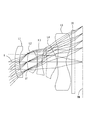
図1に示すように、本実施形態の撮像レンズは、物体側から像面側に向かって順に、正の屈折力を有する第1レンズL1と、開口絞りSTと、正の屈折力を有する第2レンズL2と、負の屈折力を有する第3レンズL3と、正の屈折力を有する第4レンズL4と、負の屈折力を有する第5レンズL5とで構成されている。 As shown in FIG. 1, the imaging lens of the present embodiment includes, in order from the object side to the image plane side, a first lens L1 having a positive refractive power, an aperture stop ST, and a first lens having a positive refractive power. The second lens L2 includes a third lens L3 having negative refractive power, a fourth lens L4 having positive refractive power, and a fifth lens L5 having negative refractive power.
また、第5レンズL5と像面IMとの間にはフィルタIRが配置されている。なお、このフィルタIRは省略することが可能である。 Further, a filter IR is disposed between the fifth lens L5 and the image plane IM. This filter IR can be omitted.
上記5枚構成の撮像レンズにおいて、第1レンズL1は物体側の面が光軸Xの近傍において凸面で、像面側の面が凹面で形成されたメニスカス形状の両面が非球面のレンズであり、第2レンズL2は物体側の面と像面側の面が共に凸面で形成された両凸形状のレンズであり、第3レンズL3は物体側の面が凸面で像面側の面が凹面のメニスカス形状のレンズであり、第4レンズL4は光軸Xの近傍で物体側の面が凹面で像面側の面が凸面のメニスカス形状のレンズであり、第5レンズL5は光軸Xの近傍で物体側の面が凸面で像面側の面が凹面のメニスカス形状のレンズである。 In the imaging lens having the five-lens configuration, the first lens L1 is a meniscus double-sided lens in which the object-side surface is a convex surface near the optical axis X and the image-side surface is a concave surface. The second lens L2 is a biconvex lens in which both the object side surface and the image side surface are convex, and the third lens L3 is a convex surface on the object side and a concave surface on the image side. The fourth lens L4 is a meniscus lens having a concave surface on the object side and a convex surface on the image surface side in the vicinity of the optical axis X, and the fifth lens L5 has an optical axis X. A meniscus lens having a convex surface on the object side and a concave surface on the image surface side in the vicinity.
第1レンズL1は、比較的弱い屈折力に設定するとともに、両面を非球面で形成しており、物体側の面の非球面形状は、光軸Xの近傍から離れる従って物体側に凸面を向けた形状から周辺部では物体側に凹面を向けた形状に変化している。このような非球面形状に形成することで、球面収差および高い像高位置での非点収差を効果的に補正している。なお、第1レンズL1は、光軸Xの近傍で物体側に凸面を向けたレンズであれば良く、実施例2のように両面が凸面であっても構わない。また、第1レンズL1は、実施例3のように負の屈折力を有していても良い。さらに、実施例7や実施例8のように、第1レンズL1と第2レンズL2との間隔を空け、有効径を大きくし、物体側の面と像面側の面を共に一様に変化する非球面形状とすれば、より広い角度からの光線を取り込むことが可能になる。 The first lens L1 is set to have a relatively weak refractive power, and both surfaces are formed as aspherical surfaces. The aspherical shape of the object-side surface is away from the vicinity of the optical axis X, so that the convex surface is directed toward the object side. The shape has changed from a curved shape to a shape with a concave surface facing the object side at the periphery. By forming such an aspherical shape, spherical aberration and astigmatism at a high image height position are effectively corrected. The first lens L1 may be a lens having a convex surface facing the object side in the vicinity of the optical axis X, and both surfaces may be convex as in the second embodiment. Further, the first lens L1 may have a negative refractive power as in the third embodiment. Further, as in Example 7 and Example 8, the distance between the first lens L1 and the second lens L2 is increased, the effective diameter is increased, and both the object side surface and the image surface side surface are uniformly changed. If the aspherical shape is used, it is possible to capture light rays from a wider angle.
第2レンズL2は、撮像レンズを構成する5枚レンズの中で比較的強い屈折力を有している。両面を凸面で形成しているため、正の屈折力を物体側の面と像面側の面とで分担させ、面の公差感度の上昇を抑えながら、強い屈折力を発生させることで光学全長を短縮している。また、第2レンズL2は像面側に凸面を向けた正の屈折力を有するレンズであれば良く、実施例4のように像面側に凸面を向けたメニスカス形状を採用することも可能である。その場合は、像面側の面に対して物体側の面の曲率半径を大きく設定することで、非点収差および像面湾曲の補正に有利になる。 The second lens L2 has a relatively strong refractive power among the five lenses constituting the imaging lens. Since both sides are convex, the positive optical power is shared between the object-side surface and the image-side surface, suppressing the increase in surface tolerance sensitivity, and generating strong refractive power while suppressing the increase in surface tolerance sensitivity. Is shortened. The second lens L2 may be a lens having a positive refractive power with the convex surface facing the image surface side, and may adopt a meniscus shape with the convex surface facing the image surface as in the fourth embodiment. is there. In that case, setting the radius of curvature of the object-side surface to be larger than the image-side surface is advantageous for correcting astigmatism and curvature of field.
第3レンズL3は像面側に凹面を向けた負の屈折力を有するレンズであり、球面収差および色収差の補正をしている。 The third lens L3 is a lens having a negative refractive power with the concave surface facing the image surface side, and corrects spherical aberration and chromatic aberration.
第4レンズL4は像面側に凸面を向けた正の屈折力を有するレンズであり、主に非点収差および像面湾曲の補正をしている。 The fourth lens L4 is a lens having a positive refractive power with the convex surface facing the image surface side, and mainly corrects astigmatism and curvature of field.
第5レンズL5は、像面側に凹面を向けたメニスカス形状の負の屈折力を有するレンズであり、バックフォーカスの確保と、物体側の面および像面側の面に形成された変極点を有する非球面形状によって、主に歪曲収差および像面湾曲を補正すると共に、撮像素子へ入射する光線の角度を制御している。 The fifth lens L5 is a meniscus lens having a negative refractive power with the concave surface facing the image surface side. The back lens is secured, and inflection points formed on the object side surface and the image surface side surface are changed. The aspherical shape that is used mainly corrects distortion and curvature of field, and controls the angle of light incident on the image sensor.
また、本実施形態の撮像レンズは、すべてプラスチック材料を採用しており、低コストで大量生産を可能にしている。より具体的には、第1レンズL1、第2レンズL2、第4レンズL4、第5レンズL5にはアッベ数が50から60の範囲の低分散なシクロオレフィン系のプラスチック材料を、第3レンズL3にはアッベ数が20から30の範囲の高分散なポリカーボネート系のプラスチック材料を採用している。第3レンズL3に上述した高分散の材料を選択することで、色収差の良好な補正が図られている。 In addition, the imaging lens of this embodiment is entirely made of a plastic material, enabling mass production at a low cost. More specifically, the first lens L1, the second lens L2, the fourth lens L4, and the fifth lens L5 are made of a low-dispersion cycloolefin plastic material having an Abbe number in the range of 50 to 60, and the third lens. For L3, a highly dispersed polycarbonate plastic material having an Abbe number in the range of 20 to 30 is used. By selecting the above-described highly dispersed material for the third lens L3, good correction of chromatic aberration is achieved.
本発明の撮像レンズは以下の条件式を満足する。
(1)0.9<ih/f<1.1
(2)0.04<|r1/r2|<2.50
(3)0.4<r6/f<0.8
(4)1.94<|r7/r8|<3.65
(5)1.33<TTL/f<2.20
(6)0.65<f2/f<1.24
(7)1.0<|r3|/f
(8)−1.6<f3/f<−1.0
ただし、
f:撮像レンズ全系の焦点距離
f2:第2レンズL2の焦点距離
f3:第3レンズL3の焦点距離
ih:最大像高
r1:第1レンズL1の物体側の面の曲率半径
r2:第1レンズL1の像面側の面の曲率半径
r3:第2レンズL2の物体側の面の曲率半径
r6:第3レンズL3の像面側の面の曲率半径
r7:第4レンズL4の物体側の面の曲率半径
r8:第4レンズL4の像面側の面の曲率半径
TTL:フィルタIR類を取り外した際の第1レンズL1の物体側の面から像面IMまでの光軸上の距離
The imaging lens of the present invention satisfies the following conditional expression.
(1) 0.9 <ih / f <1.1
(2) 0.04 <| r1 / r2 | <2.50
(3) 0.4 <r6 / f <0.8
(4) 1.94 <| r7 / r8 | <3.65
(5) 1.33 <TTL / f <2.20
(6) 0.65 <f2 / f <1.24
(7) 1.0 <| r3 | / f
(8) -1.6 <f3 / f <-1.0
However,
f: focal length of the entire imaging lens system f2: focal length of the second lens L2 f3: focal length of the third lens L3 ih: maximum image height r1: radius of curvature of the object side surface of the first lens L1 r2: first R3: radius of curvature of object side surface of second lens L2 r6: radius of curvature of image side surface of third lens L3 r7: radius of curvature of object side of fourth lens L4 Radius of curvature of surface r8: Radius of curvature of image surface side of fourth lens L4 TTL: Distance on the optical axis from the object side surface of first lens L1 to image surface IM when filter IRs are removed
本実施形態では、すべてのレンズ面を非球面で形成している。これらのレンズ面に採用する非球面形状は光軸方向の軸をZ、光軸に直交する方向の高さをH、円錐係数をk、非球面係数をA4、A6、A8、A10、A12、A14、A16としたとき数式1により表わされる。
In the present embodiment, all lens surfaces are aspherical. The aspherical shape adopted for these lens surfaces is Z in the optical axis direction, H in the direction perpendicular to the optical axis, k in the conical coefficient, A4, A6, A8, A10, A12, When A14 and A16 are set, they are expressed by

次に本実施形態に係る撮像レンズの実施例を示す。各実施例において、fは撮像レンズ全系の焦点距離を、FnoはFナンバーを、ωは半画角を、ihは最大像高をそれぞれ示す。また、iは物体側から数えた面番号、rは曲率半径、dは光軸上のレンズ面間の距離(面間隔)、Ndはd線(基準波長)の屈折率、νdはd線に対するアッベ数をそれぞれ示す。なお、非球面に関しては、面番号iの後に*(アスタリスク)の符号を付加して示す。 Next, examples of the imaging lens according to this embodiment will be described. In each embodiment, f represents the focal length of the entire imaging lens system, Fno represents the F number, ω represents the half field angle, and ih represents the maximum image height. Further, i is a surface number counted from the object side, r is a radius of curvature, d is a distance (surface interval) between lens surfaces on the optical axis, Nd is a refractive index of d-line (reference wavelength), and νd is relative to d-line. The Abbe numbers are shown. As for the aspherical surface, a surface number i is added after the symbol * (asterisk).
基本的なレンズデータを以下の表1に示す。 Basic lens data is shown in Table 1 below.
実施例1の撮像レンズは、表9に示すように条件式(1)から(8)の全てを満たしている。 The imaging lens of Example 1 satisfies all of the conditional expressions (1) to (8) as shown in Table 9.
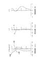
図2は実施例1の撮像レンズについて、球面収差(mm)、非点収差(mm)、歪曲収差(%)を示したものである。球面収差図は、F線(486nm)、d線(588nm)、C線(656nm)の各波長に対する収差量を示している。また、非点収差図にはサジタル像面S、タンジェンシャル像面Tにおける収差量をそれぞれ示している(図4、図6、図8、図10、図12、図14、図16においても同じ)。図2に示すように、各収差は良好に補正されていることが分かる。 FIG. 2 shows spherical aberration (mm), astigmatism (mm), and distortion (%) for the imaging lens of Example 1. The spherical aberration diagram shows the amount of aberration with respect to each wavelength of the F line (486 nm), the d line (588 nm), and the C line (656 nm). The astigmatism diagrams show the aberration amounts on the sagittal image surface S and the tangential image surface T (the same applies to FIGS. 4, 6, 8, 10, 12, 14, and 16). ). As shown in FIG. 2, it can be seen that each aberration is well corrected.
また、約90°の広い画角を達成し、F値は2.4程度の明るい撮像レンズ系が実現されている。さらに、光学全長TTLは4.24mmと短く、光学全長TTLと最大像高ihとの比(TTL/2ih)が0.74であり、5枚構成でありながら薄型化が実現されている。 Also, a bright imaging lens system that achieves a wide angle of view of about 90 ° and an F value of about 2.4 is realized. Further, the optical total length TTL is as short as 4.24 mm, and the ratio (TTL / 2ih) between the optical total length TTL and the maximum image height ih is 0.74, and the thinning is realized even though the configuration is five sheets.
基本的なレンズデータを以下の表2に示す。 Basic lens data is shown in Table 2 below.
実施例2の撮像レンズは、表9に示すように条件式(1)から(8)の全てを満たしている。 The imaging lens of Example 2 satisfies all the conditional expressions (1) to (8) as shown in Table 9.
図4は実施例2の撮像レンズについて、球面収差(mm)、非点収差(mm)、歪曲収差(%)を示したものである。図4に示すように、各収差は良好に補正されていることが分かる。 FIG. 4 shows spherical aberration (mm), astigmatism (mm), and distortion (%) for the imaging lens of Example 2. As shown in FIG. 4, it can be seen that each aberration is well corrected.
また、約90°の広い画角を達成し、F値は2.4程度の明るい撮像レンズ系が実現されている。さらに、光学全長TTLは4.23mmと短く、光学全長TTLと最大像高ihとの比(TTL/2ih)が0.74であり、5枚構成でありながら薄型化が実現されている。 Also, a bright imaging lens system that achieves a wide angle of view of about 90 ° and an F value of about 2.4 is realized. Further, the optical total length TTL is as short as 4.23 mm, and the ratio (TTL / 2ih) between the optical total length TTL and the maximum image height ih is 0.74, so that the thinning is realized even though the configuration is five sheets.
基本的なレンズデータを以下の表3に示す。
実施例3の撮像レンズは、表9に示すように条件式(1)から(8)の全てを満たしている。 The imaging lens of Example 3 satisfies all the conditional expressions (1) to (8) as shown in Table 9.
図6は実施例3の撮像レンズについて、球面収差(mm)、非点収差(mm)、歪曲収差(%)を示したものである。図6に示すように、各収差は良好に補正されていることが分かる。 FIG. 6 shows spherical aberration (mm), astigmatism (mm), and distortion (%) for the imaging lens of Example 3. As shown in FIG. 6, it can be seen that each aberration is corrected satisfactorily.
また、約90°の広い画角を達成し、F値は2.4程度の明るい撮像レンズ系が実現されている。さらに、光学全長TTLは4.54mmと短く、光学全長TTLと最大像高ihとの比(TTL/2ih)が0.79であり、5枚構成でありながら薄型化が実現されている。 Also, a bright imaging lens system that achieves a wide angle of view of about 90 ° and an F value of about 2.4 is realized. Further, the optical total length TTL is as short as 4.54 mm, and the ratio (TTL / 2ih) between the optical total length TTL and the maximum image height ih is 0.79, and the thinning is realized even though the configuration is five sheets.
基本的なレンズデータを以下の表4に示す。
実施例4の撮像レンズは、表9に示すように条件式(1)から(8)の全てを満たしている。 The imaging lens of Example 4 satisfies all conditional expressions (1) to (8) as shown in Table 9.
図8は実施例4の撮像レンズについて、球面収差(mm)、非点収差(mm)、歪曲収差(%)を示したものである。図8に示すように、各収差は良好に補正されていることが分かる。 FIG. 8 shows spherical aberration (mm), astigmatism (mm), and distortion (%) for the imaging lens of Example 4. As shown in FIG. 8, it can be seen that each aberration is corrected satisfactorily.
また、約90°の広い画角を達成し、F値は2.4程度の明るい撮像レンズ系が実現されている。さらに、光学全長TTLは4.03mmと短く、光学全長TTLと最大像高ihとの比(TTL/2ih)が0.71であり、5枚構成でありながら薄型化が実現されている。 Also, a bright imaging lens system that achieves a wide angle of view of about 90 ° and an F value of about 2.4 is realized. Further, the optical total length TTL is as short as 4.03 mm, and the ratio (TTL / 2ih) between the optical total length TTL and the maximum image height ih is 0.71, and thinning is realized despite the five-lens configuration.
基本的なレンズデータを以下の表5に示す。
実施例5の撮像レンズは、表9に示すように条件式(1)から(8)の全てを満たしている。 The imaging lens of Example 5 satisfies all conditional expressions (1) to (8) as shown in Table 9.
図10は実施例5の撮像レンズについて、球面収差(mm)、非点収差(mm)、歪曲収差(%)を示したものである。図10に示すように、各収差は良好に補正されていることが分かる。 FIG. 10 shows spherical aberration (mm), astigmatism (mm), and distortion (%) for the imaging lens of Example 5. As shown in FIG. 10, it can be seen that each aberration is corrected satisfactorily.
また、約90°の広い画角を達成し、F値は2.4程度の明るい撮像レンズ系が実現されている。さらに、光学全長TTLは4.03mmと短く、光学全長TTLと最大像高ihとの比(TTL/2ih)が0.71であり、5枚構成でありながら薄型化が実現されている。 Also, a bright imaging lens system that achieves a wide angle of view of about 90 ° and an F value of about 2.4 is realized. Further, the optical total length TTL is as short as 4.03 mm, and the ratio (TTL / 2ih) between the optical total length TTL and the maximum image height ih is 0.71, and thinning is realized despite the five-lens configuration.
基本的なレンズデータを以下の表6に示す。
実施例6の撮像レンズは、表9に示すように条件式(1)から(8)の全てを満たしている。 The imaging lens of Example 6 satisfies all the conditional expressions (1) to (8) as shown in Table 9.
図12は実施例6の撮像レンズについて、球面収差(mm)、非点収差(mm)、歪曲収差(%)を示したものである。図12に示すように、各収差は良好に補正されていることが分かる。 FIG. 12 shows spherical aberration (mm), astigmatism (mm), and distortion (%) for the imaging lens of Example 6. As shown in FIG. 12, it can be seen that each aberration is corrected satisfactorily.
また、約90°の広い画角を達成し、F値は2.4程度の明るい撮像レンズ系が実現されている。さらに、光学全長TTLは4.05mmと短く、光学全長TTLと最大像高ihとの比(TTL/2ih)が0.71であり、5枚構成でありながら薄型化が実現されている。 Also, a bright imaging lens system that achieves a wide angle of view of about 90 ° and an F value of about 2.4 is realized. Further, the optical total length TTL is as short as 4.05 mm, and the ratio (TTL / 2ih) between the optical total length TTL and the maximum image height ih is 0.71, and thinning is realized despite the five-lens configuration.
基本的なレンズデータを以下の表7に示す。
実施例7の撮像レンズは、表9に示すように条件式(1)から(8)の全てを満たしている。 The imaging lens of Example 7 satisfies all of the conditional expressions (1) to (8) as shown in Table 9.
図14は実施例7の撮像レンズについて、球面収差(mm)、非点収差(mm)、歪曲収差(%)を示したものである。図14に示すように、各収差は良好に補正されていることが分かる。 FIG. 14 shows spherical aberration (mm), astigmatism (mm), and distortion (%) for the imaging lens of Example 7. As shown in FIG. 14, it can be seen that each aberration is corrected satisfactorily.
また、約93°の広い画角を達成し、F値は2.2程度の明るい撮像レンズ系が実現されている。さらに、光学全長TTLは4.22mmと短く、光学全長TTLと最大像高ihとの比(TTL/2ih)が0.93であり、5枚構成でありながら薄型化が実現されている。 In addition, a bright imaging lens system that achieves a wide angle of view of about 93 ° and an F value of about 2.2 is realized. Further, the optical total length TTL is as short as 4.22 mm, and the ratio (TTL / 2ih) between the optical total length TTL and the maximum image height ih is 0.93, and the thinning is realized despite the five-lens configuration.
基本的なレンズデータを以下の表8に示す。
実施例8の撮像レンズは、表9に示すように条件式(1)から(8)の全てを満たしている。 The imaging lens of Example 8 satisfies all conditional expressions (1) to (8) as shown in Table 9.
図16は実施例8の撮像レンズについて、球面収差(mm)、非点収差(mm)、歪曲収差(%)を示したものである。図16に示すように、各収差は良好に補正されていることが分かる。 FIG. 16 shows spherical aberration (mm), astigmatism (mm), and distortion (%) for the imaging lens of Example 8. As shown in FIG. 16, it can be seen that each aberration is corrected satisfactorily.
また、約93°の広い画角を達成し、F値は2.2程度の明るい撮像レンズ系が実現されている。さらに、光学全長TTLは4.02mmと短く、光学全長TTLと最大像高ihとの比(TTL/2ih)が0.89であり、5枚構成でありながら薄型化が実現されている。 In addition, a bright imaging lens system that achieves a wide angle of view of about 93 ° and an F value of about 2.2 is realized. Further, the optical total length TTL is as short as 4.02 mm, and the ratio (TTL / 2ih) between the optical total length TTL and the maximum image height ih is 0.89, and the thinning is realized despite the five-lens configuration.
以上、説明したように、本発明の実施形態に係る撮像レンズは、撮影画角が約90°から93°の広い画角を達成しながら、収差が良好に補正された光学系を可能にする。また、光学全長と最大像高ihとの比(TTL/2ih)は1.0以下から0.8以下を達成するほどの薄型化が図られている。さらにF値は2.2から2.4程度の明るい撮像レンズ系の実現を可能にする。 As described above, the imaging lens according to the embodiment of the present invention enables an optical system in which aberrations are well corrected while achieving a wide field angle of about 90 ° to 93 °. . Further, a reduction in thickness is achieved so that the ratio (TTL / 2ih) between the optical total length and the maximum image height ih is 1.0 or less and 0.8 or less. Furthermore, it is possible to realize a bright imaging lens system having an F value of about 2.2 to 2.4.
表9に実施例1から8に係る条件式(1)から(8)の値を示す。 Table 9 shows values of conditional expressions (1) to (8) according to Examples 1 to 8.
本発明の各実施の形態に係る5枚構成の撮像レンズは、小型化、薄型化が進むスマートフォンや携帯電話機およびPDA(Personal Digital Assistant)などの携帯端末機器等、さらには、ゲーム機やPCなどの情報端末機器等に搭載される撮像装置に内蔵する光学系に適用した場合、当該カメラの広角化と高性能化を図ることができる。 The imaging lens having a five-lens configuration according to each embodiment of the present invention is a mobile terminal device such as a smart phone, a mobile phone, and a PDA (Personal Digital Assistant) that is becoming smaller and thinner, and further, a game machine, a PC, and the like When the present invention is applied to an optical system built in an imaging device mounted on an information terminal device or the like, the camera can have a wider angle and higher performance.
ST 開口絞り
L1 第1レンズ
L2 第2レンズ
L3 第3レンズ
L4 第4レンズ
L5 第5レンズ
IR フィルタ
IM 像面
ST Aperture stop L1 First lens L2 Second lens L3 Third lens L4 Fourth lens L5 Fifth lens IR filter IM Image plane
Claims (6)
(1)0.9<ih/f<1.1
(4)2.15≦|r7/r8|<3.65
(6)0.65<f2/f<1.24
ただし、
f :撮像レンズ全系の焦点距離
ih:最大像高
r7:第4レンズの物体側の面の曲率半径
r8:第4レンズの像面側の面の曲率半径
f2:第2レンズの焦点距離 An imaging lens for a solid-state imaging device, wherein a first lens having a positive or negative refractive power in the vicinity of the optical axis and having a positive or negative refractive power in the vicinity of the optical axis in order from the object side to the image plane side; An aperture stop, a second lens having a positive refractive power with a convex surface facing the image surface side, a third lens having a negative refractive power with a concave surface facing the image surface side, and a convex surface facing the image surface side A fourth lens having a positive refractive power and a fifth lens having a negative refractive power in the meniscus shape having a concave surface facing the image plane in the vicinity of the optical axis. The following conditional expressions (1) , ( 2) An imaging lens characterized by satisfying 4) and (6) .
(1) 0.9 <ih / f <1.1
(4) 2.15 ≦ | r7 / r8 | <3.65
(6) 0.65 <f2 / f <1.24
However,
f: Focal length of the entire imaging lens system ih: Maximum image height
r7: radius of curvature of the object side surface of the fourth lens
r8: radius of curvature of the image side surface of the fourth lens
f2: focal length of the second lens
(2)0.04<|r1/r2|<2.50
ただし、
r1:第1レンズの物体側の面の曲率半径
r2:第1レンズの像面側の面の曲率半径 The imaging lens according to claim 1, wherein the following conditional expression (2) is satisfied.
(2) 0.04 <| r1 / r2 | <2.50
However,
r1: radius of curvature of the object side surface of the first lens r2: radius of curvature of the image side surface of the first lens
(3)0.4<r6/f<0.8
ただし、
r6:第3レンズの像面側の面の曲率半径 The imaging lens according to claim 1, wherein the following conditional expression (3) is satisfied.
(3) 0.4 <r6 / f <0.8
However,
r6: radius of curvature of the image side surface of the third lens
(5)1.33<TTL/f<2.20
ただし、
TTL:フィルタ類を取り外した際の第1レンズの物体側の面から像面までの光軸上の距離 The imaging lens according to claim 1, wherein the following conditional expression (5) is satisfied.
(5) 1.33 <TTL / f <2.20
However,
TTL: Distance on the optical axis from the object side surface of the first lens to the image plane when the filters are removed
(7) 1.0<|r3|/f
ただし、
r3:第2レンズの物体側の面の曲率半径 The imaging lens according to claim 2, wherein the following conditional expression (7) is satisfied.
(7) 1.0 <| r3 | / f
However,
r3: radius of curvature of the object side surface of the second lens
(8) −1.6<f3/f<−1.0
ただし、
f3:第3レンズの焦点距離 The imaging lens according to claim 1, wherein the following conditional expression (8) is satisfied.
(8) -1.6 <f3 / f <-1.0
However,
f3: focal length of the third lens
Priority Applications (3)
| Application Number | Priority Date | Filing Date | Title |
|---|---|---|---|
| JP2013030313A JP6105317B2 (en) | 2013-01-25 | 2013-02-19 | Wide-angle imaging lens |
| CN201320761035.8U CN203606555U (en) | 2013-01-25 | 2013-11-27 | Wide angle pick-up lens |
| US14/146,761 US9134511B2 (en) | 2013-01-25 | 2014-01-03 | Imaging lens |
Applications Claiming Priority (3)
| Application Number | Priority Date | Filing Date | Title |
|---|---|---|---|
| JP2013011847 | 2013-01-25 | ||
| JP2013011847 | 2013-01-25 | ||
| JP2013030313A JP6105317B2 (en) | 2013-01-25 | 2013-02-19 | Wide-angle imaging lens |
Publications (3)
| Publication Number | Publication Date |
|---|---|
| JP2014160141A JP2014160141A (en) | 2014-09-04 |
| JP2014160141A5 JP2014160141A5 (en) | 2016-03-17 |
| JP6105317B2 true JP6105317B2 (en) | 2017-03-29 |
Family
ID=50719219
Family Applications (1)
| Application Number | Title | Priority Date | Filing Date |
|---|---|---|---|
| JP2013030313A Active JP6105317B2 (en) | 2013-01-25 | 2013-02-19 | Wide-angle imaging lens |
Country Status (3)
| Country | Link |
|---|---|
| US (1) | US9134511B2 (en) |
| JP (1) | JP6105317B2 (en) |
| CN (1) | CN203606555U (en) |
Families Citing this family (42)
| Publication number | Priority date | Publication date | Assignee | Title |
|---|---|---|---|---|
| US9804358B2 (en) * | 2013-04-01 | 2017-10-31 | Sony Corporation | Bright large aperture imaging lens and imaging unit |
| TWI470267B (en) | 2013-10-14 | 2015-01-21 | Largan Precision Co Ltd | Optical image capturing system, image capturing device and mobile terminal |
| TWI487939B (en) | 2013-11-08 | 2015-06-11 | Largan Precision Co Ltd | Optical photographing lens assembly, image capturing device and electronic mobile terminal |
| KR20150091695A (en) * | 2014-02-03 | 2015-08-12 | 삼성전자주식회사 | Photographing lens and photographing apparatus |
| US9557627B2 (en) * | 2014-03-07 | 2017-01-31 | Apple Inc. | Folded camera lens systems |
| TWI485425B (en) | 2014-05-26 | 2015-05-21 | Largan Precision Co Ltd | Imaging optical system, image capturing device and mobile terminal |
| KR101709830B1 (en) * | 2014-08-28 | 2017-02-23 | 삼성전기주식회사 | Optical system |
| KR101659165B1 (en) * | 2014-09-30 | 2016-09-22 | 삼성전기주식회사 | Optical system |
| TWI545342B (en) | 2014-11-06 | 2016-08-11 | 玉晶光電股份有限公司 | Imaging lens and electronic apparatus utilizing the imaging lens |
| KR102004798B1 (en) | 2014-11-18 | 2019-10-01 | 삼성전기주식회사 | Lens module |
| KR101701008B1 (en) | 2014-11-28 | 2017-01-31 | 삼성전기주식회사 | Optical system |
| CN105739060B (en) * | 2014-12-10 | 2018-01-02 | 大立光电股份有限公司 | Optical imaging lens group, image-taking device and electronic installation |
| TWI546563B (en) * | 2014-12-10 | 2016-08-21 | 先進光電科技股份有限公司 | Optical image capturing system |
| TWI623771B (en) * | 2014-12-10 | 2018-05-11 | 先進光電科技股份有限公司 | Optical image capturing system |
| CN105093495B (en) * | 2015-03-17 | 2017-11-10 | 玉晶光电(厦门)有限公司 | The electronic installation of optical imaging lens and the application optical imaging lens |
| TWI599811B (en) * | 2015-06-05 | 2017-09-21 | 先進光電科技股份有限公司 | Optical image capturing system |
| TWI599792B (en) * | 2015-06-05 | 2017-09-21 | 先進光電科技股份有限公司 | Optical image capturing system |
| KR20170050723A (en) * | 2015-10-30 | 2017-05-11 | 삼성전자주식회사 | Lens assembly and electronic device with the same |
| KR101813334B1 (en) * | 2015-11-24 | 2017-12-28 | 삼성전기주식회사 | Optical Imaging System |
| KR102117514B1 (en) | 2015-11-26 | 2020-06-01 | 삼성전기주식회사 | Optical Imaging System |
| TWI611204B (en) | 2015-12-15 | 2018-01-11 | 大立光電股份有限公司 | Imaging lens assembly, image capturing apparatus and electronic device |
| TWI601994B (en) * | 2015-12-15 | 2017-10-11 | 大立光電股份有限公司 | Imaging optical lens assembly, image capturing apparatus and electronic device |
| CN106932883B (en) * | 2015-12-30 | 2020-02-18 | 信泰光学(深圳)有限公司 | Optical lens |
| KR101901978B1 (en) * | 2016-03-18 | 2018-09-27 | 주식회사 에이스솔루텍 | Photographic lens optical system |
| KR20170109468A (en) * | 2016-03-21 | 2017-09-29 | 주식회사 에이스솔루텍 | Photographic lens optical system |
| TWI625546B (en) * | 2016-11-09 | 2018-06-01 | 大立光電股份有限公司 | Photographing optical lens system, imaging apparatus and electronic device |
| CN106526799B (en) * | 2016-11-28 | 2019-03-01 | 河北汉光重工有限责任公司 | A kind of high stability, high energy laser receive camera lens |
| CN106970456B (en) * | 2017-01-20 | 2020-01-14 | 玉晶光电(厦门)有限公司 | Optical lens group |
| TWI629501B (en) * | 2017-04-28 | 2018-07-11 | 聲遠精密光學股份有限公司 | Wide angle imaging lens assembly |
| JP2019035828A (en) * | 2017-08-12 | 2019-03-07 | ナンチャン オー−フィルム オプティカル−エレクトロニック テック カンパニー リミテッド | Imaging optical system |
| TWI790224B (en) * | 2018-03-12 | 2023-01-21 | 大陸商信泰光學(深圳)有限公司 | Lens assembly |
| CN111123472B (en) * | 2018-11-01 | 2023-03-24 | 佳能企业股份有限公司 | Optical lens |
| US20210033824A1 (en) * | 2019-08-01 | 2021-02-04 | Apple Inc. | Lens System |
| KR102327737B1 (en) * | 2020-05-26 | 2021-11-17 | 삼성전기주식회사 | Optical Imaging System |
| CN113946031B (en) * | 2020-07-15 | 2022-10-21 | 新巨科技股份有限公司 | Five-piece type wide-angle lens group |
| CN111929846B (en) * | 2020-09-22 | 2020-12-18 | 瑞泰光学(常州)有限公司 | Image pickup optical lens |
| CN112596206A (en) * | 2020-12-18 | 2021-04-02 | 四川都乐光电科技有限公司 | Wide-angle lens of mobile phone |
| CN113109927B (en) * | 2021-04-27 | 2024-04-05 | 玉晶光电(厦门)有限公司 | Optical imaging lens |
| CN113281879B (en) * | 2021-04-30 | 2022-06-24 | 江西晶超光学有限公司 | Optical system, lens module and electronic equipment |
| CN113296241B (en) * | 2021-06-15 | 2022-06-17 | 辽宁中蓝光电科技有限公司 | Small-size super-wide-angle lens |
| CN113589484B (en) * | 2021-08-03 | 2023-07-14 | 浙江舜宇光学有限公司 | Optical imaging lens |
| CN116107072B (en) * | 2023-04-13 | 2023-09-01 | 江西联益光学有限公司 | optical lens |
Family Cites Families (13)
| Publication number | Priority date | Publication date | Assignee | Title |
|---|---|---|---|---|
| JP2009075141A (en) | 2006-09-06 | 2009-04-09 | Fujinon Corp | Imaging lens and camera system including the same |
| CN100582856C (en) * | 2007-09-06 | 2010-01-20 | 鸿富锦精密工业(深圳)有限公司 | Lens system |
| JP5298682B2 (en) | 2008-07-24 | 2013-09-25 | コニカミノルタ株式会社 | Imaging lens |
| JP5607398B2 (en) * | 2009-04-07 | 2014-10-15 | 富士フイルム株式会社 | IMAGING LENS, IMAGING DEVICE, AND PORTABLE TERMINAL DEVICE |
| JP5368171B2 (en) | 2009-05-21 | 2013-12-18 | パナソニック株式会社 | Imaging lens and imaging apparatus using the same |
| TWI418877B (en) * | 2010-12-15 | 2013-12-11 | Largan Precision Co | Imagery optical system |
| JP5654384B2 (en) * | 2011-02-28 | 2015-01-14 | カンタツ株式会社 | Imaging lens |
| KR101897055B1 (en) * | 2011-08-31 | 2018-10-29 | 엘지이노텍 주식회사 | Optical system |
| TWI452331B (en) | 2012-03-08 | 2014-09-11 | Largan Precision Co Ltd | Optical image lens assembly |
| TWI435103B (en) | 2012-04-06 | 2014-04-21 | Largan Precision Co Ltd | Optical imaging lens system |
| TWI461731B (en) | 2012-05-18 | 2014-11-21 | Largan Precision Co Ltd | Image lens system |
| TWI474069B (en) | 2012-06-05 | 2015-02-21 | Largan Precision Co Ltd | Image capturing optical lens assembly |
| TWI437259B (en) | 2012-07-27 | 2014-05-11 | Largan Precision Co Ltd | Optical image capturing lens system |
-
2013
- 2013-02-19 JP JP2013030313A patent/JP6105317B2/en active Active
- 2013-11-27 CN CN201320761035.8U patent/CN203606555U/en not_active Expired - Lifetime
-
2014
- 2014-01-03 US US14/146,761 patent/US9134511B2/en active Active
Also Published As
| Publication number | Publication date |
|---|---|
| CN203606555U (en) | 2014-05-21 |
| US9134511B2 (en) | 2015-09-15 |
| JP2014160141A (en) | 2014-09-04 |
| US20140211328A1 (en) | 2014-07-31 |
Similar Documents
| Publication | Publication Date | Title |
|---|---|---|
| JP6105317B2 (en) | Wide-angle imaging lens | |
| JP6709564B2 (en) | Imaging lens | |
| JP6144954B2 (en) | Imaging lens | |
| JP6167348B2 (en) | Imaging lens | |
| JP6351171B2 (en) | Imaging lens with 7 optical elements | |
| JP6529320B2 (en) | Imaging lens | |
| JP5992868B2 (en) | Imaging device | |
| JP6358752B2 (en) | Imaging lens | |
| JP5800438B2 (en) | Imaging lens and imaging device provided with imaging lens | |
| JP6226369B2 (en) | Wide-angle imaging lens | |
| JP5985904B2 (en) | Imaging lens | |
| JP5818702B2 (en) | Imaging lens | |
| JP6332851B2 (en) | Imaging lens | |
| JP6324824B2 (en) | Imaging lens | |
| JP6710473B2 (en) | Imaging lens | |
| JP6005941B2 (en) | Imaging lens | |
| JP2016095460A (en) | Imaging lens and imaging apparatus including imaging lens | |
| JP2016114803A (en) | Image capturing lens and image capturing device having the same | |
| JP2016085390A (en) | Image capturing lens and image capturing device having the same | |
| JP2014102408A (en) | Image capturing lens | |
| JP5818866B2 (en) | Imaging lens | |
| JP2014112131A (en) | Imaging lens | |
| JP2012208326A (en) | Imaging lens | |
| JP2015169889A (en) | Imaging lens and imaging apparatus including the imaging lens | |
| JP2015187699A (en) | Imaging lens and imaging device equipped with imaging lens |
Legal Events
| Date | Code | Title | Description |
|---|---|---|---|
| A521 | Request for written amendment filed |
Free format text: JAPANESE INTERMEDIATE CODE: A523 Effective date: 20160201 |
|
| A621 | Written request for application examination |
Free format text: JAPANESE INTERMEDIATE CODE: A621 Effective date: 20160201 |
|
| RD02 | Notification of acceptance of power of attorney |
Free format text: JAPANESE INTERMEDIATE CODE: A7422 Effective date: 20160201 |
|
| RD02 | Notification of acceptance of power of attorney |
Free format text: JAPANESE INTERMEDIATE CODE: A7422 Effective date: 20160924 |
|
| RD04 | Notification of resignation of power of attorney |
Free format text: JAPANESE INTERMEDIATE CODE: A7424 Effective date: 20160926 |
|
| A131 | Notification of reasons for refusal |
Free format text: JAPANESE INTERMEDIATE CODE: A131 Effective date: 20161129 |
|
| A977 | Report on retrieval |
Free format text: JAPANESE INTERMEDIATE CODE: A971007 Effective date: 20161130 |
|
| A521 | Request for written amendment filed |
Free format text: JAPANESE INTERMEDIATE CODE: A523 Effective date: 20161227 |
|
| TRDD | Decision of grant or rejection written | ||
| A01 | Written decision to grant a patent or to grant a registration (utility model) |
Free format text: JAPANESE INTERMEDIATE CODE: A01 Effective date: 20170131 |
|
| A61 | First payment of annual fees (during grant procedure) |
Free format text: JAPANESE INTERMEDIATE CODE: A61 Effective date: 20170302 |
|
| R150 | Certificate of patent or registration of utility model |
Ref document number: 6105317 Country of ref document: JP Free format text: JAPANESE INTERMEDIATE CODE: R150 |
|
| S531 | Written request for registration of change of domicile |
Free format text: JAPANESE INTERMEDIATE CODE: R313531 |
|
| R350 | Written notification of registration of transfer |
Free format text: JAPANESE INTERMEDIATE CODE: R350 |
|
| R250 | Receipt of annual fees |
Free format text: JAPANESE INTERMEDIATE CODE: R250 |
|
| R250 | Receipt of annual fees |
Free format text: JAPANESE INTERMEDIATE CODE: R250 |
|
| S111 | Request for change of ownership or part of ownership |
Free format text: JAPANESE INTERMEDIATE CODE: R313113 |
|
| R371 | Transfer withdrawn |
Free format text: JAPANESE INTERMEDIATE CODE: R371 |
|
| S111 | Request for change of ownership or part of ownership |
Free format text: JAPANESE INTERMEDIATE CODE: R313113 |
|
| R350 | Written notification of registration of transfer |
Free format text: JAPANESE INTERMEDIATE CODE: R350 |
|
| R250 | Receipt of annual fees |
Free format text: JAPANESE INTERMEDIATE CODE: R250 |
|
| R250 | Receipt of annual fees |
Free format text: JAPANESE INTERMEDIATE CODE: R250 |
|
| R350 | Written notification of registration of transfer |
Free format text: JAPANESE INTERMEDIATE CODE: R350 |
|
| R350 | Written notification of registration of transfer |
Free format text: JAPANESE INTERMEDIATE CODE: R350 |
|
| R250 | Receipt of annual fees |
Free format text: JAPANESE INTERMEDIATE CODE: R250 |