JP2015114114A - Method for evaluating mechanical characteristic of thin-plate material, method for selecting thin-plate material using the same, and selected thin-plate material - Google Patents
Method for evaluating mechanical characteristic of thin-plate material, method for selecting thin-plate material using the same, and selected thin-plate material Download PDFInfo
- Publication number
- JP2015114114A JP2015114114A JP2013254011A JP2013254011A JP2015114114A JP 2015114114 A JP2015114114 A JP 2015114114A JP 2013254011 A JP2013254011 A JP 2013254011A JP 2013254011 A JP2013254011 A JP 2013254011A JP 2015114114 A JP2015114114 A JP 2015114114A
- Authority
- JP
- Japan
- Prior art keywords
- plate material
- thin plate
- bending
- test
- elastic modulus
- Prior art date
- Legal status (The legal status is an assumption and is not a legal conclusion. Google has not performed a legal analysis and makes no representation as to the accuracy of the status listed.)
- Pending
Links
- 239000000463 material Substances 0.000 claims description 106
- 238000012360 testing method Methods 0.000 claims description 104
- 238000005452 bending Methods 0.000 claims description 80
- 238000011156 evaluation Methods 0.000 claims description 38
- 238000000034 method Methods 0.000 claims description 31
- 238000013001 point bending Methods 0.000 claims description 22
- 238000005259 measurement Methods 0.000 claims description 19
- 239000011521 glass Substances 0.000 claims description 18
- 239000000758 substrate Substances 0.000 claims description 17
- 239000011347 resin Substances 0.000 claims description 15
- 229920005989 resin Polymers 0.000 claims description 15
- 239000004744 fabric Substances 0.000 claims description 8
- 239000000835 fiber Substances 0.000 claims description 4
- 238000006073 displacement reaction Methods 0.000 claims description 2
- 230000000052 comparative effect Effects 0.000 description 10
- 239000011342 resin composition Substances 0.000 description 9
- 238000004519 manufacturing process Methods 0.000 description 7
- 238000010187 selection method Methods 0.000 description 7
- ZWEHNKRNPOVVGH-UHFFFAOYSA-N 2-Butanone Chemical compound CCC(C)=O ZWEHNKRNPOVVGH-UHFFFAOYSA-N 0.000 description 6
- 239000002966 varnish Substances 0.000 description 5
- RYGMFSIKBFXOCR-UHFFFAOYSA-N Copper Chemical compound [Cu] RYGMFSIKBFXOCR-UHFFFAOYSA-N 0.000 description 4
- 239000002313 adhesive film Substances 0.000 description 4
- 229920001187 thermosetting polymer Polymers 0.000 description 4
- MEVBAGCIOOTPLF-UHFFFAOYSA-N 2-[[5-(oxiran-2-ylmethoxy)naphthalen-2-yl]oxymethyl]oxirane Chemical compound C1OC1COC(C=C1C=CC=2)=CC=C1C=2OCC1CO1 MEVBAGCIOOTPLF-UHFFFAOYSA-N 0.000 description 3
- FXHOOIRPVKKKFG-UHFFFAOYSA-N N,N-Dimethylacetamide Chemical compound CN(C)C(C)=O FXHOOIRPVKKKFG-UHFFFAOYSA-N 0.000 description 3
- 229920000459 Nitrile rubber Polymers 0.000 description 3
- OAICVXFJPJFONN-UHFFFAOYSA-N Phosphorus Chemical compound [P] OAICVXFJPJFONN-UHFFFAOYSA-N 0.000 description 3
- 239000000919 ceramic Substances 0.000 description 3
- 229910052802 copper Inorganic materials 0.000 description 3
- 239000010949 copper Substances 0.000 description 3
- 239000003822 epoxy resin Substances 0.000 description 3
- RAXXELZNTBOGNW-UHFFFAOYSA-N imidazole Natural products C1=CNC=N1 RAXXELZNTBOGNW-UHFFFAOYSA-N 0.000 description 3
- 125000005439 maleimidyl group Chemical group C1(C=CC(N1*)=O)=O 0.000 description 3
- 229910052698 phosphorus Inorganic materials 0.000 description 3
- 239000011574 phosphorus Substances 0.000 description 3
- 229920000647 polyepoxide Polymers 0.000 description 3
- 239000004065 semiconductor Substances 0.000 description 3
- PLIKAWJENQZMHA-UHFFFAOYSA-N 4-aminophenol Chemical compound NC1=CC=C(O)C=C1 PLIKAWJENQZMHA-UHFFFAOYSA-N 0.000 description 2
- 229920002799 BoPET Polymers 0.000 description 2
- UFWIBTONFRDIAS-UHFFFAOYSA-N Naphthalene Chemical compound C1=CC=CC2=CC=CC=C21 UFWIBTONFRDIAS-UHFFFAOYSA-N 0.000 description 2
- VYPSYNLAJGMNEJ-UHFFFAOYSA-N Silicium dioxide Chemical compound O=[Si]=O VYPSYNLAJGMNEJ-UHFFFAOYSA-N 0.000 description 2
- 150000001875 compounds Chemical class 0.000 description 2
- 238000001035 drying Methods 0.000 description 2
- 238000005530 etching Methods 0.000 description 2
- 238000002156 mixing Methods 0.000 description 2
- 239000000203 mixture Substances 0.000 description 2
- 239000005011 phenolic resin Substances 0.000 description 2
- 229920000139 polyethylene terephthalate Polymers 0.000 description 2
- 239000005020 polyethylene terephthalate Substances 0.000 description 2
- 238000010992 reflux Methods 0.000 description 2
- 229910000679 solder Inorganic materials 0.000 description 2
- JYEUMXHLPRZUAT-UHFFFAOYSA-N 1,2,3-triazine Chemical compound C1=CN=NN=C1 JYEUMXHLPRZUAT-UHFFFAOYSA-N 0.000 description 1
- GUIACFHOZIQGKX-UHFFFAOYSA-N 1-[4-[4-(2,5-dioxopyrrol-1-yl)phenyl]sulfonylphenyl]pyrrole-2,5-dione Chemical compound O=C1C=CC(=O)N1C1=CC=C(S(=O)(=O)C=2C=CC(=CC=2)N2C(C=CC2=O)=O)C=C1 GUIACFHOZIQGKX-UHFFFAOYSA-N 0.000 description 1
- ARXJGSRGQADJSQ-UHFFFAOYSA-N 1-methoxypropan-2-ol Chemical compound COCC(C)O ARXJGSRGQADJSQ-UHFFFAOYSA-N 0.000 description 1
- XNWFRZJHXBZDAG-UHFFFAOYSA-N 2-METHOXYETHANOL Chemical compound COCCO XNWFRZJHXBZDAG-UHFFFAOYSA-N 0.000 description 1
- ZCUJYXPAKHMBAZ-UHFFFAOYSA-N 2-phenyl-1h-imidazole Chemical compound C1=CNC(C=2C=CC=CC=2)=N1 ZCUJYXPAKHMBAZ-UHFFFAOYSA-N 0.000 description 1
- HYDATEKARGDBKU-UHFFFAOYSA-N 4-[4-[4-(4-aminophenoxy)phenyl]phenoxy]aniline Chemical group C1=CC(N)=CC=C1OC1=CC=C(C=2C=CC(OC=3C=CC(N)=CC=3)=CC=2)C=C1 HYDATEKARGDBKU-UHFFFAOYSA-N 0.000 description 1
- 229910002012 Aerosil® Inorganic materials 0.000 description 1
- 239000004952 Polyamide Substances 0.000 description 1
- 230000002378 acidificating effect Effects 0.000 description 1
- 230000001588 bifunctional effect Effects 0.000 description 1
- 238000006243 chemical reaction Methods 0.000 description 1
- 239000003795 chemical substances by application Substances 0.000 description 1
- 239000011248 coating agent Substances 0.000 description 1
- 238000000576 coating method Methods 0.000 description 1
- 230000006835 compression Effects 0.000 description 1
- 238000007906 compression Methods 0.000 description 1
- 238000001816 cooling Methods 0.000 description 1
- 239000011889 copper foil Substances 0.000 description 1
- XLJMAIOERFSOGZ-UHFFFAOYSA-M cyanate Chemical compound [O-]C#N XLJMAIOERFSOGZ-UHFFFAOYSA-M 0.000 description 1
- 238000013461 design Methods 0.000 description 1
- 238000011161 development Methods 0.000 description 1
- 239000003085 diluting agent Substances 0.000 description 1
- BXKDSDJJOVIHMX-UHFFFAOYSA-N edrophonium chloride Chemical compound [Cl-].CC[N+](C)(C)C1=CC=CC(O)=C1 BXKDSDJJOVIHMX-UHFFFAOYSA-N 0.000 description 1
- 229910021485 fumed silica Inorganic materials 0.000 description 1
- 239000005350 fused silica glass Substances 0.000 description 1
- 238000010438 heat treatment Methods 0.000 description 1
- 125000002887 hydroxy group Chemical group [H]O* 0.000 description 1
- 150000002460 imidazoles Chemical class 0.000 description 1
- 239000011256 inorganic filler Substances 0.000 description 1
- 229910003475 inorganic filler Inorganic materials 0.000 description 1
- 238000007689 inspection Methods 0.000 description 1
- 230000010354 integration Effects 0.000 description 1
- 239000012948 isocyanate Substances 0.000 description 1
- 150000002513 isocyanates Chemical class 0.000 description 1
- 238000010030 laminating Methods 0.000 description 1
- 229910052751 metal Inorganic materials 0.000 description 1
- 239000002184 metal Substances 0.000 description 1
- 150000002739 metals Chemical class 0.000 description 1
- 239000012046 mixed solvent Substances 0.000 description 1
- 239000010680 novolac-type phenolic resin Substances 0.000 description 1
- 239000002245 particle Substances 0.000 description 1
- ISWSIDIOOBJBQZ-UHFFFAOYSA-N phenol group Chemical group C1(=CC=CC=C1)O ISWSIDIOOBJBQZ-UHFFFAOYSA-N 0.000 description 1
- 229920002647 polyamide Polymers 0.000 description 1
- -1 polyethylene terephthalate Polymers 0.000 description 1
- 238000007788 roughening Methods 0.000 description 1
- 239000007787 solid Substances 0.000 description 1
- 239000002904 solvent Substances 0.000 description 1
- 239000000126 substance Substances 0.000 description 1
- 125000001424 substituent group Chemical group 0.000 description 1
- 239000013077 target material Substances 0.000 description 1
- 238000010998 test method Methods 0.000 description 1
- 239000013585 weight reducing agent Substances 0.000 description 1
Images
Landscapes
- Investigating Strength Of Materials By Application Of Mechanical Stress (AREA)
Abstract
Description
本発明は、曲げ強度が強く、高弾性で取り扱い性に優れており、半導体パッケージ用やプリント配線板用に好適な薄板状積層板の機械特性評価方法及びその評価方法を用いたそれらの選別方法、選別された薄板状材料に関する。 The present invention is a method for evaluating the mechanical properties of a thin laminated board having a high bending strength, high elasticity and excellent handleability, and suitable for use in semiconductor packages and printed wiring boards, and a selection method using the evaluation method. The present invention relates to a selected sheet material.
近年、電子機器の小型化、軽量化、多機能化が一段と進み、これに伴い、LSIやチップ部品等の高集積化が進みその形態も多ピン化、小型化へと急速に変化している。このため多層プリント配線板は、電子部品の実装密度を向上するために、微細配線化の開発が進められている。これらの要求に合致する多層プリント配線板の製造方法として、ビルトアップ方式があり、軽量化や小型化、微細化に適した手法として主流になりつつある。
このような動向に対して、コア基材をより薄くし、高い配線密度の状態でビルドアップ層数を低減する必要が生じているが、コア基材の薄型化と鉛フリーはんだの適用によるリフローの高温化が相まって、はんだ実装時に反りが生じやすくなり、またチップとコア基材の熱膨張係数の差に起因するクラックが発生しやすくなっている。このような背景から、低熱膨張性や高弾性を有するコア基材が求められている。また、コア基材の薄型化に伴い、コア基材の機械強度が低下し、取り扱い性の悪化が懸念されることから、コア基材の高強度化も必要とされている。
一方、コア基材の薄型化に伴い、コア基材の評価方法についても課題が表面化してきた。すなわち、従来はコア基材の弾性率をJIS規格(例えばJIS R 1601の「ファインセラミックスの室温曲げ強さ試験方法」)やIPC規格(例えばIPC−TM−650 2.4.4)に定められる3点曲げ試験により評価していたが、これらの規格は厚さ0.8mm以上の材料にしか対応しておらず、厚さ0.8mm未満のコア基材については、強度や弾性率の試験の規格がなく、評価をすることが出来なかった。
In recent years, electronic devices have become smaller, lighter, and more functional, and along with this, higher integration of LSIs and chip components has progressed, and the form has rapidly changed to multi-pin and miniaturization. . For this reason, in order to improve the mounting density of electronic components, the development of micro wiring has been advanced for multilayer printed wiring boards. There is a built-up method as a method for manufacturing a multilayer printed wiring board meeting these requirements, and it is becoming mainstream as a method suitable for weight reduction, miniaturization, and miniaturization.
In response to these trends, it is necessary to make the core base material thinner and reduce the number of build-up layers with a high wiring density. However, reflow by reducing the thickness of the core base material and applying lead-free solder In combination with the increase in temperature, warpage is likely to occur during solder mounting, and cracks due to the difference in thermal expansion coefficient between the chip and the core substrate are likely to occur. From such a background, a core base material having low thermal expansibility and high elasticity is required. Moreover, since the mechanical strength of a core base material falls with the thinning of a core base material and a handleability is aggravated, the core base material is also required to have high strength.
On the other hand, with the thinning of the core base material, problems have been surfaced with respect to the evaluation method of the core base material. That is, conventionally, the elastic modulus of the core base material is defined by JIS standards (for example, “room temperature bending strength test method of fine ceramics” of JIS R 1601) and IPC standards (for example, IPC-TM-650 2.4.4). Although evaluated by a three-point bending test, these standards only deal with materials with a thickness of 0.8 mm or more, and for core base materials with a thickness of less than 0.8 mm, test for strength and elastic modulus. Because there was no standard, it was not possible to evaluate.
また、3点曲げ試験において、下部2支点間の距離が可変な冶具を用いることで、厚さ0.8mm以下の材料についても強度を簡易的に求める装置が提案されている(島津製作所Siチップ曲げ専用システムetc)。
しかし、下部2支点間の距離が可変な冶具を使用した場合、厚さ0.8mm未満の板状材料では試料が滑る等の理由で、厚さ0.8mm以上の板状材料と同等の強度および弾性率の値を得ることができず、厚さ0.8mm以上の板状材料の測定結果を再現することができなかった。更に、下部2支点間の距離が可変な冶具を使用した場合、冶具の耐熱性に問題があることから室温(5〜35℃)での測定に限られていた。以上のことから、厚さ0.8mm未満の板状材料を厚さ0.8mm以上の板状材料と同等の強度、弾性率が得られるような評価方法や、室温以上の温度における板状材料の強度、弾性率の評価方法がこれまでなかった。
本発明は、かかる事情に鑑みなされたものであり、0.8mm未満の薄板状材料に適用可能な強度(最大曲げ応力)及び曲げ弾性率を再現性よく測定できる薄板状材料の機械特性評価方法を提供すると同時に、前記評価方法を用いて薄板状材料(コア基材)を選別する選別方法、選別され特性の良好な積層板およびプリント配線板を提供することを目的とするものである。
In a three-point bending test, there has been proposed an apparatus for easily obtaining the strength of a material having a thickness of 0.8 mm or less by using a jig with a variable distance between the lower two fulcrums (Shimadzu Corporation Si chip). Bending system etc).
However, when a jig with a variable distance between the lower two fulcrums is used, the strength of the plate-like material with a thickness of 0.8 mm or more is equivalent to the strength of the plate-like material with a thickness of 0.8 mm or more because the sample slides in the plate-like material with a thickness of less than 0.8 mm. Further, the value of the elastic modulus could not be obtained, and the measurement result of the plate material having a thickness of 0.8 mm or more could not be reproduced. Furthermore, when a jig with a variable distance between the lower two fulcrums is used, there is a problem with the heat resistance of the jig, so that the measurement is limited to room temperature (5-35 ° C.). From the above, a plate-like material having a thickness of less than 0.8 mm, an evaluation method for obtaining the same strength and elastic modulus as a plate-like material having a thickness of 0.8 mm or more, and a plate-like material at a temperature of room temperature or higher There has been no evaluation method for strength and elastic modulus.
The present invention has been made in view of such circumstances, and is a method for evaluating mechanical properties of a thin plate material that can measure strength (maximum bending stress) and bending elastic modulus applicable to a thin plate material of less than 0.8 mm with high reproducibility. At the same time, it is an object of the present invention to provide a sorting method for sorting a thin plate-like material (core substrate) using the evaluation method, a laminated board and a printed wiring board that are sorted and have good characteristics.
本発明者らは上記の課題を解決するために鋭意研究を行った結果、厚さ0.8mm未満の板状材料の3点曲げ試験において、2支点間距離Lと、試験速度vを所定の範囲の値とすることによって、10℃〜350℃の温度条件下において再現性良く正確な強度、及び弾性率の値が得られることを見出し、本発明に到達した。
即ち、本発明は、以下の薄板状材料の評価方法およびその評価方法を用いた選別方法、その選別方法によって選別された積層板およびプリント配線板を提供するものである。
[1] 薄板状材料の機械特性評価方法であって、機械特性が前記薄板状材料の試験片を一定距離に配置された2支点上に置き、支点間の中央の1点に荷重を加える3点曲げ試験による最大荷重から求まる最大曲げ応力を前記薄板状材料の強度とする強度評価方法であり、下記式(1)〜(4)の試験片、測定条件により前記薄板状材料の3点曲げ試験を行い、下記式(5)により前記薄板状材料の強度(最大曲げ応力)を評価する薄板状材料の機械特性評価方法。
0.05≦t<0.8 ‥‥(1)
0.8≦L<12.8 ‥‥(2)
0.01≦v≦0.5 ‥‥(3)
10≦T≦350 ‥‥(4)
(式(1)〜(4)中、tは、試験片の厚さ(mm)、Lは、2支点間距離(mm)、vは、試験速度(mm/min)、Tは、試験温度(℃)を示す。)
σ=3FL/2Wt2 ‥‥(5)
(式(5)中、σは、最大曲げ応力、Fは、曲げ荷重、Lは、支点間距離、Wは、試験片の幅、tは、試験片の厚さを示す。)
[2]薄板状材料の機械特性評価方法であって、機械特性が、前記薄板状材料の試験片を一定距離に配置された2支点上に置き、支点間の中央の1点に荷重を加える3点曲げ試験による曲げ変位量と荷重の大きさから求まる弾性率の最大値を前記薄板状材料の曲げ弾性率とする弾性率評価方法であり、下記式(1)〜(4)の試験片、測定条件により前記薄板状材料の3点曲げ試験を行い、下記式(6)により前記薄板状材料の曲げ弾性率を評価する薄板状材料の機械特性評価方法。
0.05≦t<0.8 ‥‥(1)
0.8≦L<12.8 ‥‥(2)
0.01≦v≦0.5 ‥‥(3)
10≦T≦350 ‥‥(4)
(式(1)〜(4)中、tは、試験片の厚さ(mm)、Lは、2支点間距離(mm)、vは、試験速度(mm/min)、Tは、試験温度(℃)を示す。)
E=L3×ΔF/(4Wt3×Δs)‥‥(6)
(式(6)中、Eは、曲げ弾性率、Lは、2支点間距離、ΔFは、曲げ荷重の変化量、Wは、試験片の幅、tは、試験片の厚さ、Δsは、たわみの変化量を示す。)
[3]前記薄板状材料が、1層以上の樹脂硬化物層と1層以上の基板層を含む積層板からなることを特徴とする、[1]または[2]に記載の薄板状材料の機械特性評価方法。
[4]前記基板層が、ガラス板、ガラスクロス、有機繊維から選ばれる少なくとも一つを含むことを特徴とする、[3]に記載の薄板状材料の機械特性評価方法。
[5]薄板状材料の選別方法であって、[1]〜[4]のいずれかに記載の薄板状材料の機械特性評価方法による強度(最大曲げ応力)または曲げ弾性率を基準にして前記薄板状材料を選別する選別方法。
[6]薄板状材料の強度が、50〜2000MPaである薄板状材料を選別する、[5]に記載の薄板状材料の選別方法。
[7]薄板状材料の曲げ弾性率が、10〜200GPaである薄板状材料を選別する、[5]または[6]に記載の薄板状材料の選別方法。
[8][5]〜[7]のいずれかに記載の薄板状材料の選別方法によって選別された薄板状材料。
[9]選別された薄板状材料が、積層板である[8]に記載の薄板状材料。
[10]積層板が、プリント配線板におけるインターポーザである[9]に記載の薄板状材料。
As a result of intensive studies to solve the above problems, the present inventors have determined that a distance L between two fulcrums and a test speed v are predetermined in a three-point bending test of a plate-like material having a thickness of less than 0.8 mm. By setting the value within the range, it was found that accurate strength and elastic modulus values could be obtained with good reproducibility under the temperature condition of 10 ° C. to 350 ° C., and the present invention was achieved.
That is, the present invention provides the following thin plate-like material evaluation method, a selection method using the evaluation method, a laminated board selected by the selection method, and a printed wiring board.
[1] A method for evaluating the mechanical properties of a thin plate material, wherein the test piece of the thin plate material is placed on two fulcrums arranged at a fixed distance, and a load is applied to one central point between the
0.05 ≦ t <0.8 (1)
0.8 ≦ L <12.8 (2)
0.01 ≦ v ≦ 0.5 (3)
10 ≦ T ≦ 350 (4)
(In the formulas (1) to (4), t is the thickness of the test piece (mm), L is the distance between two fulcrums (mm), v is the test speed (mm / min), and T is the test temperature. (° C.)
σ = 3FL / 2Wt 2 (5)
(In formula (5), σ is the maximum bending stress, F is the bending load, L is the distance between the fulcrums, W is the width of the test piece, and t is the thickness of the test piece.)
[2] A method for evaluating the mechanical properties of a thin plate-like material, the mechanical properties of which are obtained by placing a test piece of the thin plate-like material on two fulcrums arranged at a fixed distance and applying a load to one central point between the fulcrums. This is an elastic modulus evaluation method in which the maximum value of the elastic modulus obtained from the bending displacement amount and the magnitude of the load by a three-point bending test is used as the bending elastic modulus of the thin plate material, and the test pieces of the following formulas (1) to (4) A method for evaluating mechanical properties of a thin plate material, wherein a three-point bending test of the thin plate material is performed according to measurement conditions, and a bending elastic modulus of the thin plate material is evaluated by the following equation (6).
0.05 ≦ t <0.8 (1)
0.8 ≦ L <12.8 (2)
0.01 ≦ v ≦ 0.5 (3)
10 ≦ T ≦ 350 (4)
(In the formulas (1) to (4), t is the thickness of the test piece (mm), L is the distance between two fulcrums (mm), v is the test speed (mm / min), and T is the test temperature. (° C.)
E = L 3 × ΔF / (4 Wt 3 × Δs) (6)
(In Equation (6), E is the flexural modulus, L is the distance between the two fulcrums, ΔF is the amount of change in bending load, W is the width of the test piece, t is the thickness of the test piece, and Δs is Indicates the amount of change in deflection.)
[3] The thin plate-like material according to [1] or [2], wherein the thin plate-like material comprises a laminated plate including one or more cured resin layers and one or more substrate layers. Mechanical property evaluation method.
[4] The method for evaluating mechanical properties of a thin plate material according to [3], wherein the substrate layer includes at least one selected from a glass plate, a glass cloth, and an organic fiber.
[5] A method for selecting a thin plate material, which is based on the strength (maximum bending stress) or the bending elastic modulus obtained by the mechanical property evaluation method for a thin plate material according to any one of [1] to [4]. A sorting method for sorting thin plate materials.
[6] The method for selecting a thin plate material according to [5], wherein the thin plate material having a strength of 50 to 2000 MPa is selected.
[7] The method for selecting a thin plate material according to [5] or [6], wherein the thin plate material having a bending elastic modulus of 10 to 200 GPa is selected.
[8] A thin plate material selected by the thin plate material selecting method according to any one of [5] to [7].
[9] The thin plate material according to [8], wherein the selected thin plate material is a laminated plate.
[10] The thin plate material according to [9], wherein the laminate is an interposer in a printed wiring board.
本発明によると、0.8mm未満の薄板状材料に適用可能な強度及び弾性率の機械特性評価方法を提供すると同時に、前記評価方法を用いて選別した薄板状材料を用いた積層板およびプリント配線板を提供することができる。 According to the present invention, a mechanical property evaluation method of strength and elastic modulus applicable to a thin plate material of less than 0.8 mm is provided, and at the same time, a laminate and a printed wiring using the thin plate material selected using the evaluation method Board can be provided.
以下、本発明の機械特性評価方法、選別方法および薄板状材料について詳細に説明する。
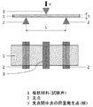
3点曲げ試験は、試験片を一定距離に配置された2支点上に置き、支点間の中央の1点に荷重を加えることで、試験片の曲げ強さ、曲げ弾性率を評価することができる。図1に、3点曲げ試験の模式的な断面図を記す。
1は試験片、2は支点であり、2支点の中央にある3によって荷重を加える。荷重が加わった試験片は徐々にたわんでいき、一定以上の荷重が加わることで破断もしくは塑性変形する。曲げ荷重が最大となったときの曲げ荷重から、最大曲げ応力を求めることができる。なお、最大曲げ応力σは、曲げ荷重をF、支点間距離をL、試験片幅をW、試験片厚さをtとすると、下記式(5)で計算することができる。本発明では、最大曲げ応力σを、試験片の強度とする。
σ=3FL/2Wt2 ‥‥(5)
Hereinafter, the mechanical property evaluation method, the selection method, and the thin plate material of the present invention will be described in detail.
In the three-point bending test, the bending strength and bending elastic modulus of the test piece can be evaluated by placing the test piece on two fulcrums arranged at a fixed distance and applying a load to one central point between the fulcrums. it can. FIG. 1 shows a schematic cross-sectional view of a three-point bending test.
1 is a test piece, 2 is a fulcrum, and a load is applied by 3 at the center of 2 fulcrum. The test piece to which the load is applied gradually bends, and breaks or plastically deforms when a load exceeding a certain level is applied. The maximum bending stress can be obtained from the bending load when the bending load becomes maximum. The maximum bending stress σ can be calculated by the following equation (5), where F is the bending load, L is the distance between the fulcrums, W is the specimen width, and t is the specimen thickness. In the present invention, the maximum bending stress σ is the strength of the test piece.
σ = 3FL / 2Wt 2 (5)
また、曲げ弾性率は、曲げ荷重−たわみ曲線の直線部の初期勾配より算出することができる。曲げ荷重の変化量をΔF、たわみの変化量をΔsとすると、曲げ弾性率Eは、式(6)で計算することができる。
E=L3×ΔF/(4Wt3×Δs)‥‥(6)
Further, the bending elastic modulus can be calculated from the initial gradient of the linear portion of the bending load-deflection curve. When the amount of change in bending load is ΔF and the amount of change in deflection is Δs, the bending elastic modulus E can be calculated by Equation (6).
E = L 3 × ΔF / (4 Wt 3 × Δs) (6)
厚さ0.8mm以上の材料においては、JISやIPCの規格によって上記の曲げ応力、曲げ弾性率を求める方法が定められている。
本発明では、試験片の厚さtが0.05mm以上、0.8mm未満の場合において、L(2支点間距離)とv(試験速度)を適切な値にすることで、再現良く、厚さ0.8mm以上の試験片を測定したときと同程度の強度と弾性率を得ることができる。
For materials having a thickness of 0.8 mm or more, a method for obtaining the above bending stress and bending elastic modulus is defined by JIS and IPC standards.
In the present invention, when the thickness t of the test piece is 0.05 mm or more and less than 0.8 mm, L (distance between two fulcrums) and v (test speed) are set to appropriate values, and the thickness is good. The same strength and elastic modulus can be obtained as when a test piece having a thickness of 0.8 mm or more is measured.
試験片の厚さtが0.05mm以上、0.8mm未満の場合において、L(2支点間距離)はtの12〜20倍とすることが再現良く、厚さ0.8mm以上の試験片を測定したときと同程度の強度と弾性率を得るうえで好ましく、14〜18倍とすることが更に好ましく、16倍とすることが最も好ましい。
また、v(試験速度)の値は、0.01〜0.5mm/minとすることが再現良く、厚さ0.8mm以上の試験片を測定したときと同程度の強度と弾性率を得るうえで好ましい。
vの値の最適値は試験片の厚さtだけでなく、試験片の強度、厚さにもよるが、vの値が厚さtの0.2倍〜5倍であると再現良く、厚さ0.8mm以上の試験片を測定したときと同程度の強度と弾性率を得るうえで好ましい。
When the thickness t of the test piece is 0.05 mm or more and less than 0.8 mm, L (distance between two fulcrums) is preferably 12 to 20 times t, and the test piece has a thickness of 0.8 mm or more. It is preferable for obtaining the same strength and elastic modulus as measured, more preferably 14 to 18 times, and most preferably 16 times.
Further, the value of v (test speed) is preferably 0.01 to 0.5 mm / min, and the strength and elastic modulus are the same as when a test piece having a thickness of 0.8 mm or more is measured. In addition, it is preferable.
The optimum value of v depends not only on the thickness t of the test piece, but also on the strength and thickness of the test piece, but when the value of v is 0.2 to 5 times the thickness t, the reproduction is good. It is preferable to obtain the same strength and elastic modulus as when a test piece having a thickness of 0.8 mm or more is measured.
本発明の3点曲げ試験の評価方法及び選別方法に使用する試験片は、薄板状材料である。
本発明で用いる薄板状材料は、厚さtが、0.05mm以上で、0.8mm未満の薄板であり、例えば、プリント配線板のように絶縁層の表面に回路が形成され、その回路厚みにより多少の凹凸がある場合でも、評価することができるので薄板状としている。
本発明では、厚みtの16倍を、2支点間距離Lとし、0.8mm以上、12.8mm未満としている。2支点間距離Lが、12.8mmでは、試験片がすべり易く、正確な値が得られない恐れがある。また、本発明では、試験速度vを0.01mm/min以上、0.5mm/min未満とする。試験速度vが、0.5mm/minを超えると試験片がすべり易く正確な値が得られない恐れがある。本発明では、2支点間距離Lが、0.8≦L<12.8mmと相当に狭い間隔であるので、支点間の中央の1点に荷重を加える治具は、試験片と接触する先端(圧子)を丸くし曲率を2mm以下、好ましくは1mm以下とする。
本発明では、実施例でも示すように試験片の幅は、試験片の長さと同じ程度で、正方形に近い形状とすることが好ましい。
The test piece used for the evaluation method and the selection method of the three-point bending test of the present invention is a thin plate material.
The thin plate material used in the present invention is a thin plate having a thickness t of 0.05 mm or more and less than 0.8 mm. For example, a circuit is formed on the surface of an insulating layer like a printed wiring board, and the circuit thickness is Therefore, even if there is some unevenness, it can be evaluated, so it is in the form of a thin plate.
In the present invention, 16 times the thickness t is the distance L between the two fulcrums, and is 0.8 mm or more and less than 12.8 mm. When the distance L between the two fulcrums is 12.8 mm, the test piece easily slips, and an accurate value may not be obtained. Moreover, in this invention, the test speed v shall be 0.01 mm / min or more and less than 0.5 mm / min. If the test speed v exceeds 0.5 mm / min, the test piece is likely to slip and an accurate value may not be obtained. In the present invention, since the distance L between the two fulcrums is a relatively narrow distance of 0.8 ≦ L <12.8 mm, the jig for applying a load to one central point between the fulcrums is the tip that contacts the test piece. The (indenter) is rounded and the curvature is 2 mm or less, preferably 1 mm or less.
In the present invention, as shown in the examples, the width of the test piece is preferably about the same as the length of the test piece and close to a square.
本発明で用いる薄板状材料としては、厚みが0.05mm以上で、0.8mm未満の1層以上の樹脂硬化物層と1層以上の基板層を含む積層板であると好ましい。この基板層は、ガラス板、ガラスクロス、有機繊維から選ばれる少なくとも一つを含むことが好ましい。例えば熱硬化性樹脂層及び基板層から構成されるものが挙げられる。基板層としては、薄板ガラス、ガラスクロス、有機繊維等からなるか、もしくは一部含まれるものを使用することができる。セラミックスを用いても良い。
また、熱硬化性樹脂としては、例えばエポキシ樹脂、フェノール樹脂、シアネート樹脂、トリアジン樹脂などを使用することができる。
また、積層板が、プリント配線板におけるインターポーザであることが好ましい。インターポーザが薄板状材料である場合、その機械的特性を評価することで品質を評価することができる。さらに、インターポーザとしての、材料、基材等の正確な測定値に基いた選択が可能となり組成設計に寄与することができる。
The thin plate material used in the present invention is preferably a laminated plate including one or more cured resin layers having a thickness of 0.05 mm or more and less than 0.8 mm and one or more substrate layers. The substrate layer preferably contains at least one selected from a glass plate, a glass cloth, and an organic fiber. For example, what is comprised from a thermosetting resin layer and a board | substrate layer is mentioned. As the substrate layer, one made of thin glass, glass cloth, organic fiber, or the like, or a part thereof can be used. Ceramics may be used.
Moreover, as a thermosetting resin, an epoxy resin, a phenol resin, cyanate resin, a triazine resin etc. can be used, for example.
Moreover, it is preferable that a laminated board is an interposer in a printed wiring board. When the interposer is a thin plate-like material, the quality can be evaluated by evaluating its mechanical characteristics. Furthermore, selection as an interposer based on accurate measured values of materials, base materials, and the like is possible, which can contribute to composition design.
本発明の薄板状材料の選別方法は、薄板状材料の機械特性評価方法による強度(最大曲げ応力)または曲げ弾性率を基準にして前記薄板状材料を選別する。
従来の評価方法では、薄板状材料の場合、試験片がすべり測定値にバラつきがあったり、試験片の表面状態により滑りやすさなどで正確な機械特性は測定できなかったが、本発明による評価方法では滑りやすさを抑制しているので、正確な測定ができることで、材料の組成、組合わせにより目標とする材料の選択、選別が可能となる。
また、量産品における品質検査による測定バラつきが少なくなるため良否判定が細かな範囲で行うことができる。
例えば、薄板状材料の強度が、50〜2000MPaである高強度な薄板状材料を選別したり、薄板状材料の曲げ弾性率が、10〜200GPaである高弾性率な薄板状材料を選別することができる。
In the method for selecting a thin plate material of the present invention, the thin plate material is selected based on the strength (maximum bending stress) or the bending elastic modulus obtained by the mechanical property evaluation method of the thin plate material.
In the conventional evaluation method, in the case of a thin plate-like material, the measurement value of the test piece may vary, and due to the surface condition of the test piece, the exact mechanical characteristics could not be measured due to slipperiness, etc. In the method, since slipperiness is suppressed, accurate measurement can be performed, so that the target material can be selected and selected by the composition and combination of the materials.
Further, since the measurement variation due to the quality inspection in the mass-produced product is reduced, the quality determination can be performed in a fine range.
For example, selecting a high-strength thin plate material with a strength of the thin plate material of 50 to 2000 MPa, or selecting a high elastic modulus thin plate material with a bending elastic modulus of the thin plate material of 10 to 200 GPa. Can do.
次に実施例により本発明を具体的に説明するが、本発明はこれらの実施例に限定されるものではない。
(実施例1)
(接着フィルムAの製造)
フェノール性水酸基含有ポリブタジエン変性ポリアミド(日本化薬株式会社製、商品名:BPAM−155)1.5gに、N、N−ジメチルアセトアミド(DMAc)を13.5g配合した後、ビフェニルアラルキル型エポキシ樹脂(日本化薬株式会社製、商品名:NC−3000H)10g、ノボラック型フェノール樹脂(DIC株式会社製、商品名:TD−2090)3.6g、硬化促進剤として2−フェニルイミダゾール(四国化成工業株式会社製、商品名:2PZ)0.1gを、ヒュームドシリカ(日本アエロジル株式会社製、商品名:R972、比表面積130m2/g)0.9gを添加した後、DMAc及びメチルエチルケトンからなる混合溶剤で希釈した(固形分濃度約25質量%)。その後、分散機(ナノマイザー、商品名、吉田機械興業株式会社製)を用いて、均一な樹脂ワニスAを得た。
次に、得られた樹脂ワニスAを、支持体の離型処理ポリエチレンテレフタレート(PET)フィルム(PET−38X、リンテック株式会社製、商品名)の離型処理面に乾燥後5μmになるように塗布し、180℃で10分間乾燥させて樹脂組成物層とPETフィルムからなる接着フィルムAを形成した。
EXAMPLES Next, although an Example demonstrates this invention concretely, this invention is not limited to these Examples.
(Example 1)
(Manufacture of adhesive film A)
After blending 13.5 g of N, N-dimethylacetamide (DMAc) with 1.5 g of phenolic hydroxyl group-containing polybutadiene-modified polyamide (Nippon Kayaku Co., Ltd., trade name: BPAM-155), biphenylaralkyl epoxy resin ( Nippon Kayaku Co., Ltd., trade name: NC-3000H) 10 g, Novolac type phenolic resin (DIC Corporation, trade name: TD-2090) 3.6 g, 2-phenylimidazole (Shikoku Chemicals Co., Ltd.) as a curing accelerator 0.1 g of company-made product name: 2PZ was added to 0.9 g of fumed silica (manufactured by Nippon Aerosil Co., Ltd., product name: R972, specific surface area 130 m 2 / g), and then mixed solvent consisting of DMAc and methyl ethyl ketone (Solid content concentration of about 25% by mass). Thereafter, a uniform resin varnish A was obtained using a disperser (Nanomizer, trade name, manufactured by Yoshida Kikai Kogyo Co., Ltd.).
Next, the obtained resin varnish A was applied to a release-treated surface of a release-treated polyethylene terephthalate (PET) film (PET-38X, manufactured by Lintec Co., Ltd.) as a support so as to be 5 μm after drying. And it was made to dry at 180 degreeC for 10 minute (s), and the adhesive film A which consists of a resin composition layer and a PET film was formed.
(薄板状材料(積層板)の作製)
次いで、以下のようにして積層体(樹脂組成物層/ガラス基板層/樹脂組成物層)を製造した。ガラス基板(ガラス基板層、厚さ150μm)の両面上に、前記の接着フィルムAの樹脂組成物層がガラス基板に当接するように配置し、バッチ式の真空加圧ラミネーター「MVLP−500」(株式会社名機製作所製、商品名)を用いてラミネートによって積層した。この際の真空度は30mmHg以下であり、温度は120℃、圧力は0.5MPaの設定とした。
室温(25℃)に冷却後、支持体のPETフィルムを剥がし、180℃で60分間硬化して、3層構造の薄板状材料である積層板(樹脂硬化物層/ガラス基板層/樹脂硬化物層)を得た。
(Production of thin plate material (laminate))
Next, a laminate (resin composition layer / glass substrate layer / resin composition layer) was produced as follows. On both surfaces of a glass substrate (glass substrate layer, thickness 150 μm), the resin composition layer of the adhesive film A is placed in contact with the glass substrate, and a batch-type vacuum pressure laminator “MVLP-500” ( The product was manufactured by laminating using a product name, manufactured by Meiki Seisakusho Co., Ltd. The degree of vacuum at this time was 30 mmHg or less, the temperature was set to 120 ° C., and the pressure was set to 0.5 MPa.
After cooling to room temperature (25 ° C.), the PET film of the support is peeled off and cured at 180 ° C. for 60 minutes to obtain a laminated sheet (resin cured product layer / glass substrate layer / resin cured product) having a three-layer structure. Layer).
(3点曲げ試験)
上記で得られた積層板から、20mm×20mmの試験片を5枚切り出した。
三点曲げ試験は、オートグラフ(株式会社島津製作所製、AG−1kNX)を用いて測定した。2支点間距離Lは3.2mm、試料の厚さtは0.17mm±0.01mm、測定温度Tは20℃、試験速度vは0.1mm/minとして測定した。
試験片の曲げ強さは、上記条件で曲げ荷重が最大となったときの応力の値とし前記式(5)から、曲げ弾性率は、試験力が10Nから20Nの範囲における曲げ荷重の変化量により前記式(6)から求めた。評価結果、曲げ強さは271MPa、曲げ弾性率は58.4GPaであった。
(3-point bending test)
Five test pieces of 20 mm × 20 mm were cut out from the laminate obtained as described above.
The three-point bending test was measured using an autograph (manufactured by Shimadzu Corporation, AG-1kNX). The distance L between the two fulcrums was 3.2 mm, the sample thickness t was 0.17 mm ± 0.01 mm, the measurement temperature T was 20 ° C., and the test speed v was 0.1 mm / min.
The bending strength of the test piece is the value of the stress when the bending load becomes maximum under the above conditions, and from the above equation (5), the bending elastic modulus is the amount of change in bending load when the test force is in the range of 10N to 20N. From the above equation (6). As a result of the evaluation, the bending strength was 271 MPa and the bending elastic modulus was 58.4 GPa.
(実施例2)
実施例1の接着フィルムAの樹脂組成物層の厚さを、乾燥後15μmとなるようにした以外は実施例1と同様の操作を行い、積層板の試験片を作製し3点曲げ試験を行った。
その評価結果、曲げ強さは185MPa、曲げ弾性率は37.0GPaであった。
(Example 2)
The same procedure as in Example 1 was performed except that the thickness of the resin composition layer of the adhesive film A of Example 1 was 15 μm after drying, and a test piece of a laminate was produced to perform a three-point bending test. went.
As a result of the evaluation, the bending strength was 185 MPa and the bending elastic modulus was 37.0 GPa.
(実施例3)
実施例2の試験片について、試験速度vは0.05mm/minとして測定した以外は実施例2と同様の操作を行った。その評価結果、曲げ強さは185MPa、曲げ弾性率は37.3GPaであった。
(Example 3)
For the test piece of Example 2, the same operation as in Example 2 was performed except that the test speed v was measured at 0.05 mm / min. As a result of the evaluation, the bending strength was 185 MPa and the bending elastic modulus was 37.3 GPa.
(実施例4)
実施例1の積層体において、ガラス基板の代わりにセラミック基板(LTCC、日立金属株式会社製、厚さ140μm)を用いた積層体を作製し、試験速度vは0.05mm/minとして測定した以外は実施例1と同様の操作を行った。その評価結果、曲げ強さは156MPa、曲げ弾性率は67.6GPaであった。
Example 4
In the laminate of Example 1, a laminate using a ceramic substrate (LTCC, manufactured by Hitachi Metals, Inc., thickness 140 μm) instead of the glass substrate was prepared, and the test speed v was measured at 0.05 mm / min. The same operation as in Example 1 was performed. As a result of the evaluation, the bending strength was 156 MPa and the bending elastic modulus was 67.6 GPa.
(実施例5)
[不飽和マレイミド基を有する樹脂組成物の溶液の製造]
温度計、攪拌装置、還流冷却管付き水分定量器の付いた加熱及び冷却可能な容積2リットルの反応容器に、4,4´−ビス(4−アミノフェノキシ)ビフェニル:69.10g、ビス(4−マレイミドフェニル)スルホン:429.90g、p−アミノフェノール:41.00g、及びプロピレングリコールモノメチルエーテル:360.00gを入れ、還流温度で2時間反応させて、酸性置換基と不飽和マレイミド基を有する樹脂組成物の溶液を得た。
(Example 5)
[Production of a resin composition solution having an unsaturated maleimide group]
In a reaction vessel with a volume of 2 liters that can be heated and cooled, equipped with a thermometer, a stirrer, and a moisture meter with a reflux condenser, 4,4′-bis (4-aminophenoxy) biphenyl: 69.10 g, bis (4 -Maleimidophenyl) sulfone: 429.90 g, p-aminophenol: 41.00 g, and propylene glycol monomethyl ether: 360.00 g, reacted at reflux temperature for 2 hours to have an acidic substituent and an unsaturated maleimide group A solution of the resin composition was obtained.
[熱硬化性樹脂組成物を含有するワニスの製造]
(1)硬化剤(A)として、上記の不飽和マレイミド基を有する樹脂組成物の溶液、
(2)熱硬化性樹脂(B)として、2官能ナフタレン型エポキシ樹脂〔DIC株式会社製、商品名、HP−4032D〕、
(3)変性イミダゾール(C)として、イソシアネートマスクイミダゾール〔第一工業製薬株式会社製、商品名:G8009L〕、
(4)無機充填剤(D)として、溶融シリカ〔株式会社アドマテック製、商品名:SC2050−KC〕、
(5)難燃性を付与するリン含有化合物(E)として、リン含有フェノール樹脂〔三光株式会社製、商品名:HCA−HQ、リン含有量9.6質量%〕、
(6)化学粗化可能な化合物(F)として、架橋アクリロニトリルブタジエンゴム(NBR)粒子〔JSR株式会社製、商品名:XER−91〕、
(7)希釈溶剤として、メチルエチルケトン、
を使用し、表1に示した配合割合(質量部)で混合して、樹脂含有量(樹脂成分の合計)65質量%の均一なワニス(G)を作製した。
[Production of varnish containing thermosetting resin composition]
(1) As a curing agent (A), a solution of a resin composition having the unsaturated maleimide group,
(2) As thermosetting resin (B), bifunctional naphthalene type epoxy resin [manufactured by DIC Corporation, trade name, HP-4032D],
(3) As modified imidazole (C), isocyanate mask imidazole [Daiichi Kogyo Seiyaku Co., Ltd., trade name: G8009L],
(4) As inorganic filler (D), fused silica [manufactured by Admatech Co., Ltd., trade name: SC2050-KC],
(5) As a phosphorus-containing compound (E) that imparts flame retardancy, a phosphorus-containing phenol resin [manufactured by Sanko Co., Ltd., trade name: HCA-HQ, phosphorus content: 9.6% by mass],
(6) As the compound (F) capable of chemical roughening, crosslinked acrylonitrile butadiene rubber (NBR) particles [manufactured by JSR Corporation, trade name: XER-91],
(7) As a diluent solvent, methyl ethyl ketone,
Were mixed at a blending ratio (parts by mass) shown in Table 1 to prepare a uniform varnish (G) having a resin content (total of resin components) of 65% by mass.

[プリプレグおよび銅張積層板の製造]
上記ワニス(G)を厚さの異なるEガラスクロスにそれぞれ含浸塗工し、160℃で10分加熱乾燥してプリプレグを得た。Eガラスクロスの種類は、旭化成イーマテリアルズ株式会社のIPC規格1078(厚み0.043mm、質量48g/m2、平織、縦53本/25mm、横53本/25mm)を用いた。このガラスクロスを用いて作製したプリプレグの樹脂含有量は、54質量%であった。前記プリプレグを、3枚重ね合わせ、12μmの電解銅箔を上下に配置し、圧力3.0MPa、温度235℃で120分間プレスを行って、銅張積層板を作製した。
[Manufacture of prepreg and copper-clad laminate]
The varnish (G) was impregnated and coated on E glass cloth having different thicknesses and dried by heating at 160 ° C. for 10 minutes to obtain a prepreg. As the type of E glass cloth, IPC standard 1078 (thickness 0.043 mm, mass 48 g / m 2 , plain weave, length 53/25 mm, width 53/25 mm) manufactured by Asahi Kasei E-Materials Co., Ltd. was used. The resin content of the prepreg produced using this glass cloth was 54% by mass. Three prepregs were superposed, 12 μm electrolytic copper foils were placed one above the other, and pressed at a pressure of 3.0 MPa and a temperature of 235 ° C. for 120 minutes to produce a copper-clad laminate.
(3点曲げ試験)
銅張積層板から銅をエッチングにより除去した後、20mm×20mmの試験片を5枚切り出した。
三点曲げ試験はオートグラフ(株式会社島津製作所製、AG−1kNX)を用いて測定した。2支点間距離Lは3.2mm、試料の厚さtは0.15mm±0.01mm、測定温度Tは20℃、試験速度vは0.1mm/minとして測定した。なお、試験の際、積層板の塗工方向が3点曲げの圧縮冶具と垂直になるように配置した。
試験片の曲げ強さは、上記条件で曲げ荷重が最大となったときの応力の値とし、曲げ弾性率は試験力が10Nから20Nの範囲における曲げ荷重の変化量により求めた結果、曲げ強さは539MPa、曲げ弾性率は24.7GPaであった。
(3-point bending test)
After removing copper from the copper-clad laminate by etching, five test pieces of 20 mm × 20 mm were cut out.
The three-point bending test was measured using an autograph (manufactured by Shimadzu Corporation, AG-1kNX). The distance L between the two fulcrums was 3.2 mm, the thickness t of the sample was 0.15 mm ± 0.01 mm, the measurement temperature T was 20 ° C., and the test speed v was 0.1 mm / min. In the test, the laminated plate was placed so that the coating direction was perpendicular to the three-point bending compression jig.
The bending strength of the test piece is the stress value when the bending load is maximized under the above conditions, and the bending elastic modulus is the bending strength obtained as a result of the change in bending load when the test force is in the range of 10N to 20N. The thickness was 539 MPa, and the flexural modulus was 24.7 GPa.
(実施例6)
実施例5の試験片について、測定温度Tを150℃とした以外は実施例5と同様の操作を行った。その評価結果、曲げ強さは440MPa、曲げ弾性率は18.0GPaであった。
(Example 6)
About the test piece of Example 5, operation similar to Example 5 was performed except the measurement temperature T having been 150 degreeC. As a result of the evaluation, the bending strength was 440 MPa, and the bending elastic modulus was 18.0 GPa.
(実施例7)
実施例5の試験片について、測定温度Tを250℃とした以外は実施例5と同様の操作を行った。その評価結果、曲げ強さは350MPa、曲げ弾性率は13.0GPaであった。
(Example 7)
About the test piece of Example 5, operation similar to Example 5 was performed except the measurement temperature T having been 250 degreeC. As a result of the evaluation, the bending strength was 350 MPa and the bending elastic modulus was 13.0 GPa.
(参考例1)
実施例5のプリプレグ製造工程において、Eガラスクロスの種類としてIPC規格2116(厚み0.095mm、質量104g/m2、平織り、縦60本/25mm、横58本/25mm)を用いプリプレグを8枚重ねた以外は、実施例6と同様の操作を行い、銅張積層板を作製した。
銅張積層板から銅をエッチングにより除去した後、25mm×25mmの試験片を5枚切り出した。三点曲げ試験はテンシロン(オリエンテック製、RTC−1350A)を用いて測定した。2支点間距離Lは20.0mm、試料の厚さtは0.81±0.01mm、測定温度Tは20℃、試験速度vは1.0mm/minとして測定した。曲げ弾性率は試験力が10Nから20Nの範囲における曲げ荷重の変化量により求めた結果、曲げ強さは540MPa、曲げ弾性率は26.9GPaであった。
(Reference Example 1)
In the prepreg manufacturing process of Example 5, IPC standard 2116 (thickness 0.095 mm, mass 104 g / m 2 , plain weave, length 60/25 mm, width 58/25 mm) was used as the type of E glass cloth, and 8 prepregs were used. Except for overlapping, the same operation as in Example 6 was performed to produce a copper clad laminate.
After removing copper from the copper-clad laminate by etching, five 25 mm × 25 mm test pieces were cut out. The three-point bending test was measured using Tensilon (Orientec, RTC-1350A). The distance L between the two fulcrums was 20.0 mm, the sample thickness t was 0.81 ± 0.01 mm, the measurement temperature T was 20 ° C., and the test speed v was 1.0 mm / min. The bending elastic modulus was determined from the amount of change in bending load when the test force was in the range of 10N to 20N. As a result, the bending strength was 540 MPa and the bending elastic modulus was 26.9 GPa.
(参考例2)
参考例1の試験片について、測定温度Tを150℃とした以外は参考例1と同様の操作を行った。その評価結果、曲げ強さは437MPa、曲げ弾性率は19.4GPaであった。
(Reference Example 2)
For the test piece of Reference Example 1, the same operation as in Reference Example 1 was performed except that the measurement temperature T was 150 ° C. As a result of the evaluation, the bending strength was 437 MPa, and the bending elastic modulus was 19.4 GPa.
(参考例3)
参考例1の試験片について、測定温度Tを250℃とした以外は参考例1と同様の操作を行った。その評価結果、曲げ強さは358MPa、曲げ弾性率は13.9GPaであった。
(Reference Example 3)
For the test piece of Reference Example 1, the same operation as in Reference Example 1 was performed except that the measurement temperature T was 250 ° C. As a result of the evaluation, the bending strength was 358 MPa and the bending elastic modulus was 13.9 GPa.
(比較例1)
実施例1の試験片について、試験速度vを1.0mm/minとした以外は実施例1と同様の操作を行った。その評価結果、曲げ強さは85MPa、曲げ弾性率は20Nの荷重がかかる前に破断したため計測不能であった。
(Comparative Example 1)
About the test piece of Example 1, operation similar to Example 1 was performed except the test speed v having been 1.0 mm / min. As a result of the evaluation, the bending strength was 85 MPa, and the flexural modulus was not measurable because it broke before the load of 20 N was applied.
(比較例2)
実施例5の試験片について、2支点間距離Lを20mmとした以外は実施例4と同様の操作を行った。その評価結果、曲げ強さは299MPa、曲げ弾性率は16.9GPaであった。
(Comparative Example 2)
For the test piece of Example 5, the same operation as in Example 4 was performed except that the distance L between the two fulcrums was 20 mm. As a result of the evaluation, the bending strength was 299 MPa and the bending elastic modulus was 16.9 GPa.
以上の実施例1〜7、参考例1〜3及び比較例1、2について、測定評価結果を纏めて表2に示した。 Table 2 summarizes the measurement evaluation results for Examples 1 to 7, Reference Examples 1 to 3, and Comparative Examples 1 and 2.
実施例1と比較例1では、試験速度が異なり(実施例1 v=0.1mm/min、比較例1 v=1.0mm/min)、実施例1の曲げ強さ271MPaに対し、試験速度の速い比較例1は、85MPaと強度が異なり、曲げ弾性率は、破断したため測定できなかった。
実施例5と比較例2では、2支点間距離が異なり(実施例1 L=3.2mm、比較例2 L=20mm)、実施例5の曲げ強さ539MPaに対し、2支点間距離の長い比較例2は、299MPaと強度が異なり、曲げ弾性率は、実施例5の24.7GPaに対し比較例2の16.9GPaといずれの値も小さくなる。従来の試験速度が高く、2支点間距離が長いと、試験片のすべりのためか実際の値よりも測定値が低めに測定される。本発明の試験片、測定条件では、試験条件をすべりが抑制されるようにしているため、正確な測定ができ、表面状態や材質によるによる滑りやすさを排除した薄板状材料の選別が可能となる。
上記から明らかなように、厚さ0.8mm未満の板状材料の3点曲げ試験において、2支点間距離Lと、試験速度vを所定の範囲の値とすることによって、10〜350℃の温度条件下において再現性良く正確な強度、及び弾性率の値が得られ、したがって曲げ強度が強く、高弾性で取り扱い性に優れており、半導体パッケージ用やプリント配線板用に好適な積層板の評価方法及び選別方法を提供することができる。
The test speed is different between Example 1 and Comparative Example 1 (Example 1 v = 0.1 mm / min, Comparative Example 1 v = 1.0 mm / min), and the test speed is compared to the bending strength 271 MPa of Example 1. The comparative example 1 with a high strength was different from 85 MPa in strength, and the flexural modulus could not be measured because it broke.
In Example 5 and Comparative Example 2, the distance between the two fulcrums is different (Example 1 L = 3.2 mm, Comparative Example 2 L = 20 mm), and the distance between the two fulcrums is longer than the bending strength 539 MPa of Example 5. Comparative Example 2 is different in strength from 299 MPa, and the flexural modulus is 26.9 GPa in Example 5 and 16.9 GPa in Comparative Example 2 and both values are smaller. When the conventional test speed is high and the distance between the two fulcrums is long, the measured value is measured lower than the actual value because of the sliding of the test piece. In the test piece and measurement conditions of the present invention, since sliding is controlled in the test conditions, accurate measurement is possible, and it is possible to select a thin plate material that eliminates slipperiness due to surface conditions and materials. Become.
As is clear from the above, in a three-point bending test of a plate-like material having a thickness of less than 0.8 mm, by setting the distance L between the two fulcrums and the test speed v to values within a predetermined range, 10 to 350 ° C. Accurate strength and elastic modulus values can be obtained with good reproducibility under temperature conditions. Therefore, the bending strength is strong, the elasticity is excellent, and the handleability is excellent. The laminated board is suitable for semiconductor packages and printed wiring boards. An evaluation method and a selection method can be provided.
本発明では、厚さ0.8mm未満の板状材料の3点曲げ試験において、2支点間距離Lと、試験速度vを所定の範囲の値とすることによって、0.8mm未満の板状材料に適用可能な強度及び弾性率の評価方法を提供すると同時に、前記評価方法を用いて選別した板状材料(コア基材)を用いた積層板およびプリント配線板を提供することができる。
従って、本発明により、曲げ強度が強く、高弾性で取り扱い性に優れており、半導体パッケージ用やプリント配線板用に好適な積層板の評価方法及び選別方法が得られ、電子機器などの製造に広く用いることができる。
In the present invention, in a three-point bending test of a plate-like material having a thickness of less than 0.8 mm, the plate-like material having a thickness of less than 0.8 mm is obtained by setting the distance L between the two fulcrums and the test speed v to values within a predetermined range. While providing the evaluation method of the intensity | strength and elasticity modulus which can be applied to, the laminated board and printed wiring board using the plate-shaped material (core base material) which selected using the said evaluation method can be provided.
Therefore, according to the present invention, it is possible to obtain an evaluation method and a selection method of a laminated board having a high bending strength, high elasticity and excellent handling property, and suitable for semiconductor packages and printed wiring boards. Can be widely used.
Claims (10)
0.05≦t<0.8 ‥‥(1)
0.8≦L<12.8 ‥‥(2)
0.01≦v≦0.5 ‥‥(3)
10≦T≦350 ‥‥(4)
(式(1)〜(4)中、tは、試験片の厚さ(mm)、Lは、2支点間距離(mm)、vは、試験速度(mm/min)、Tは、試験温度(℃)を示す。)
σ=3FL/2Wt2 ‥‥(5)
(式(5)中、σは、最大曲げ応力、Fは、曲げ荷重、Lは、支点間距離、Wは、試験片の幅、tは、試験片の厚さを示す。) This is a method for evaluating the mechanical properties of a thin plate material, wherein the mechanical properties of the thin plate material are placed on two fulcrums arranged at a fixed distance, and a load is applied to one central point between the fulcrums. This is a strength evaluation method in which the maximum bending stress obtained from the maximum load obtained by the above is used as the strength of the thin plate-like material, and a three-point bending test is performed on the thin plate-like material according to the test pieces of the following formulas (1) to (4) and measurement conditions. A method for evaluating the mechanical properties of a thin plate material, wherein the strength (maximum bending stress) of the thin plate material is evaluated by the following formula (5).
0.05 ≦ t <0.8 (1)
0.8 ≦ L <12.8 (2)
0.01 ≦ v ≦ 0.5 (3)
10 ≦ T ≦ 350 (4)
(In the formulas (1) to (4), t is the thickness of the test piece (mm), L is the distance between two fulcrums (mm), v is the test speed (mm / min), and T is the test temperature. (° C.)
σ = 3FL / 2Wt 2 (5)
(In formula (5), σ is the maximum bending stress, F is the bending load, L is the distance between the fulcrums, W is the width of the test piece, and t is the thickness of the test piece.)
0.05≦t<0.8 ‥‥(1)
0.8≦L<12.8 ‥‥(2)
0.01≦v≦0.5 ‥‥(3)
10≦T≦350 ‥‥(4)
(式(1)〜(4)中、tは、試験片の厚さ(mm)、Lは、2支点間距離(mm)、vは、試験速度(mm/min)、Tは、試験温度(℃)を示す。)
E=L3×ΔF/(4Wt3×Δs)‥‥(6)
(式(6)中、Eは、曲げ弾性率、Lは、2支点間距離、ΔFは、曲げ荷重の変化量、Wは、試験片の幅、tは、試験片の厚さ、Δsは、たわみの変化量を示す。) A method for evaluating mechanical properties of a thin plate material, wherein the mechanical properties are determined by a three-point bending method in which a specimen of the thin plate material is placed on two fulcrums arranged at a fixed distance and a load is applied to one central point between the fulcrums. This is an elastic modulus evaluation method in which the maximum value of the elastic modulus obtained from the amount of bending displacement and the load obtained by the test is the bending elastic modulus of the thin plate material, and the test pieces and measurement conditions of the following formulas (1) to (4) A method for evaluating the mechanical properties of a thin plate material, in which a three-point bending test is performed on the thin plate material and the bending elastic modulus of the thin plate material is evaluated by the following equation (6).
0.05 ≦ t <0.8 (1)
0.8 ≦ L <12.8 (2)
0.01 ≦ v ≦ 0.5 (3)
10 ≦ T ≦ 350 (4)
(In the formulas (1) to (4), t is the thickness of the test piece (mm), L is the distance between two fulcrums (mm), v is the test speed (mm / min), and T is the test temperature. (° C.)
E = L 3 × ΔF / (4 Wt 3 × Δs) (6)
(In Equation (6), E is the flexural modulus, L is the distance between the two fulcrums, ΔF is the amount of change in bending load, W is the width of the test piece, t is the thickness of the test piece, and Δs is Indicates the amount of change in deflection.)
Priority Applications (1)
| Application Number | Priority Date | Filing Date | Title |
|---|---|---|---|
| JP2013254011A JP2015114114A (en) | 2013-12-09 | 2013-12-09 | Method for evaluating mechanical characteristic of thin-plate material, method for selecting thin-plate material using the same, and selected thin-plate material |
Applications Claiming Priority (1)
| Application Number | Priority Date | Filing Date | Title |
|---|---|---|---|
| JP2013254011A JP2015114114A (en) | 2013-12-09 | 2013-12-09 | Method for evaluating mechanical characteristic of thin-plate material, method for selecting thin-plate material using the same, and selected thin-plate material |
Publications (1)
| Publication Number | Publication Date |
|---|---|
| JP2015114114A true JP2015114114A (en) | 2015-06-22 |
Family
ID=53528060
Family Applications (1)
| Application Number | Title | Priority Date | Filing Date |
|---|---|---|---|
| JP2013254011A Pending JP2015114114A (en) | 2013-12-09 | 2013-12-09 | Method for evaluating mechanical characteristic of thin-plate material, method for selecting thin-plate material using the same, and selected thin-plate material |
Country Status (1)
| Country | Link |
|---|---|
| JP (1) | JP2015114114A (en) |
Cited By (10)
| Publication number | Priority date | Publication date | Assignee | Title |
|---|---|---|---|---|
| CN105891009A (en) * | 2016-05-06 | 2016-08-24 | 中国人民解放军国防科学技术大学 | Biological bone small-dimensional sample three-point bending test device |
| CN106323763A (en) * | 2016-11-23 | 2017-01-11 | 海南省农业科学院农产品加工设计研究所 | Detection method for betel nut fiber softness |
| JP2017067454A (en) * | 2015-09-28 | 2017-04-06 | パナソニックIpマネジメント株式会社 | Floor material analysis method |
| CN107063849A (en) * | 2016-12-18 | 2017-08-18 | 内蒙古航天红岗机械有限公司 | A kind of flat board torsion test fixture |
| CN108195707A (en) * | 2017-12-29 | 2018-06-22 | 大连理工大学 | The evaluation method that a kind of ultralow temperature cooling influences material mechanical performance |
| JP2021117206A (en) * | 2020-01-29 | 2021-08-10 | 株式会社ディスコ | Chip strength measurement method, test equipment, and chip strength calculation method |
| CN113836638A (en) * | 2021-09-18 | 2021-12-24 | 中航西安飞机工业集团股份有限公司 | Layout method for determining flat plate structure under pure bending load |
| CN113836639A (en) * | 2021-09-18 | 2021-12-24 | 中航西安飞机工业集团股份有限公司 | Layout method for determining flat plate structure under bending and compression load |
| CN116337649A (en) * | 2023-05-29 | 2023-06-27 | 云南滇坡机械设备有限公司 | Automobile anti-collision beam bending test device |
| CN116990117A (en) * | 2023-09-26 | 2023-11-03 | 德阳利宇风和新材料有限公司 | Quality testing equipment and method for superconductive aluminum-based copper-clad plate |
Citations (5)
| Publication number | Priority date | Publication date | Assignee | Title |
|---|---|---|---|---|
| JPH06308002A (en) * | 1993-04-23 | 1994-11-04 | Meidensha Corp | Three-point bending jig for small fragile material |
| JPH11292662A (en) * | 1997-12-16 | 1999-10-26 | Ngk Insulators Ltd | Fiber composite material and its use |
| JP2006083044A (en) * | 2004-09-17 | 2006-03-30 | Hitachi Ltd | Glass member |
| JP2008069044A (en) * | 2006-09-14 | 2008-03-27 | Hitachi Metals Ltd | Ceramic substrate, ceramic circuit substrate and semiconductor module using the same |
| JP2009023904A (en) * | 2007-06-20 | 2009-02-05 | Ngk Insulators Ltd | Manufacturing method of ceramic laminated body and ceramic laminated body |
-
2013
- 2013-12-09 JP JP2013254011A patent/JP2015114114A/en active Pending
Patent Citations (5)
| Publication number | Priority date | Publication date | Assignee | Title |
|---|---|---|---|---|
| JPH06308002A (en) * | 1993-04-23 | 1994-11-04 | Meidensha Corp | Three-point bending jig for small fragile material |
| JPH11292662A (en) * | 1997-12-16 | 1999-10-26 | Ngk Insulators Ltd | Fiber composite material and its use |
| JP2006083044A (en) * | 2004-09-17 | 2006-03-30 | Hitachi Ltd | Glass member |
| JP2008069044A (en) * | 2006-09-14 | 2008-03-27 | Hitachi Metals Ltd | Ceramic substrate, ceramic circuit substrate and semiconductor module using the same |
| JP2009023904A (en) * | 2007-06-20 | 2009-02-05 | Ngk Insulators Ltd | Manufacturing method of ceramic laminated body and ceramic laminated body |
Non-Patent Citations (2)
| Title |
|---|
| 植村 益次: "FRPの力学的特性試験法の問題点と設計基準(II)", 日本複合材料学会誌, vol. 7, no. 2, JPN6017029925, 1981, pages 74 - 81, ISSN: 0003762248 * |
| 橋本 清司 他: "電子デバイス用薄膜のヤング率測定用精密3点曲げ試験装置の開発と測定例", 材料, vol. 43, no. 489, JPN6017029927, June 1994 (1994-06-01), pages 703 - 709, ISSN: 0003616149 * |
Cited By (15)
| Publication number | Priority date | Publication date | Assignee | Title |
|---|---|---|---|---|
| JP2017067454A (en) * | 2015-09-28 | 2017-04-06 | パナソニックIpマネジメント株式会社 | Floor material analysis method |
| CN105891009A (en) * | 2016-05-06 | 2016-08-24 | 中国人民解放军国防科学技术大学 | Biological bone small-dimensional sample three-point bending test device |
| CN106323763A (en) * | 2016-11-23 | 2017-01-11 | 海南省农业科学院农产品加工设计研究所 | Detection method for betel nut fiber softness |
| CN107063849B (en) * | 2016-12-18 | 2022-02-18 | 内蒙古航天红岗机械有限公司 | Flat plate distortion test fixture |
| CN107063849A (en) * | 2016-12-18 | 2017-08-18 | 内蒙古航天红岗机械有限公司 | A kind of flat board torsion test fixture |
| CN108195707A (en) * | 2017-12-29 | 2018-06-22 | 大连理工大学 | The evaluation method that a kind of ultralow temperature cooling influences material mechanical performance |
| JP2021117206A (en) * | 2020-01-29 | 2021-08-10 | 株式会社ディスコ | Chip strength measurement method, test equipment, and chip strength calculation method |
| JP7390200B2 (en) | 2020-01-29 | 2023-12-01 | 株式会社ディスコ | Chip strength measurement method, testing device, and chip strength calculation method |
| CN113836638A (en) * | 2021-09-18 | 2021-12-24 | 中航西安飞机工业集团股份有限公司 | Layout method for determining flat plate structure under pure bending load |
| CN113836639A (en) * | 2021-09-18 | 2021-12-24 | 中航西安飞机工业集团股份有限公司 | Layout method for determining flat plate structure under bending and compression load |
| CN113836638B (en) * | 2021-09-18 | 2024-08-09 | 中航西安飞机工业集团股份有限公司 | Layout method for determining flat plate structure under pure bending load |
| CN116337649A (en) * | 2023-05-29 | 2023-06-27 | 云南滇坡机械设备有限公司 | Automobile anti-collision beam bending test device |
| CN116337649B (en) * | 2023-05-29 | 2024-04-12 | 苏州首测检测技术有限公司 | Automobile anti-collision beam bending test device |
| CN116990117A (en) * | 2023-09-26 | 2023-11-03 | 德阳利宇风和新材料有限公司 | Quality testing equipment and method for superconductive aluminum-based copper-clad plate |
| CN116990117B (en) * | 2023-09-26 | 2024-01-12 | 德阳利宇风和新材料有限公司 | Quality testing equipment and method for superconductive aluminum-based copper-clad plate |
Similar Documents
| Publication | Publication Date | Title |
|---|---|---|
| JP2015114114A (en) | Method for evaluating mechanical characteristic of thin-plate material, method for selecting thin-plate material using the same, and selected thin-plate material | |
| KR101398342B1 (en) | Resin composition, prepreg, laminate, and wiring board | |
| US6187416B1 (en) | Resin composition for copper-clad laminate, resin-coated copper foil, multilayered copper-clad laminate, and multilayered printed circuit board | |
| JP5344022B2 (en) | Epoxy resin composition, prepreg, laminate, resin sheet, printed wiring board, and semiconductor device | |
| TWI610982B (en) | Resin composition and finished product obtained therefrom | |
| JP2010248495A (en) | Thermosetting insulating resin composition, and insulating film with support, prepreg, laminate plate and multilayer printed wiring board using the same | |
| TWI653141B (en) | Laminated body, laminated board, multilayer laminated board, printed wiring board, and manufacturing method of laminated board (1) | |
| JP5195582B2 (en) | Thermosetting insulating resin composition, and insulating film with support, prepreg, laminate and multilayer printed wiring board using the same | |
| KR20120116394A (en) | Resin composition for use in formation of bonding layer in multilayer flexible printed circuit board, resin varnish, resin-coated copper foil, manufacturing method for resin-coated copper foil for use in manufacturing of multilayer flexible printed circuit board, and multilayer flexible printed circuit board | |
| JP5589292B2 (en) | Thermosetting insulating resin composition, and insulating film with support, prepreg, laminate and multilayer printed wiring board using the same | |
| JP2011103480A (en) | Method for manufacturing multi-layer printed wiring board | |
| JP2011052188A (en) | Thermosetting insulating resin composition and insulating film with substrate, prepreg, laminated board, and multilayer printed wiring board using the same | |
| CN108026301B (en) | Method for determination of thermal stress of prepregs, metal-clad laminates, wiring boards, and wiring board materials | |
| JP2008007756A (en) | Viscoelastic resin composition, prepreg, conductor-clad laminate, resin-coated metal foil, and resin film | |
| JP3821728B2 (en) | Prepreg | |
| JP2013239701A (en) | Interlayer dielectric film with carrier material, and multilayer printed circuit board using the same | |
| US20230356498A1 (en) | Organic core material, production method for same, laminate including organic core material, and circuit board | |
| US20080032103A1 (en) | Multilayer Printed Circuit Board | |
| JP2003268136A (en) | Prepreg and laminate | |
| CN106009508B (en) | Thermosetting resin composition, metal-clad laminate, insulating sheet, printed wiring board, manufacturing method of printed wiring board, and package substrate | |
| JP2004277671A (en) | Prepreg and printed circuit board using the same | |
| JPWO2015072262A1 (en) | Metal-clad laminate, circuit board, and electronic device | |
| JP2007002071A (en) | Prepreg, circuit board and semiconductor device | |
| JP2008174662A (en) | Resin composition, insulating resin sheet with film or metallic foil, multilayered printed circuit board and semiconductor device | |
| JP2002187937A (en) | Epoxy resin composition, prepreg, and metal-clad laminate |
Legal Events
| Date | Code | Title | Description |
|---|---|---|---|
| A621 | Written request for application examination |
Free format text: JAPANESE INTERMEDIATE CODE: A621 Effective date: 20161121 |
|
| A977 | Report on retrieval |
Free format text: JAPANESE INTERMEDIATE CODE: A971007 Effective date: 20170718 |
|
| A131 | Notification of reasons for refusal |
Free format text: JAPANESE INTERMEDIATE CODE: A131 Effective date: 20170808 |
|
| A521 | Request for written amendment filed |
Free format text: JAPANESE INTERMEDIATE CODE: A523 Effective date: 20171006 |
|
| A02 | Decision of refusal |
Free format text: JAPANESE INTERMEDIATE CODE: A02 Effective date: 20180322 |