JP2015085206A - Separation membrane module cleaning method - Google Patents
Separation membrane module cleaning method Download PDFInfo
- Publication number
- JP2015085206A JP2015085206A JP2012031559A JP2012031559A JP2015085206A JP 2015085206 A JP2015085206 A JP 2015085206A JP 2012031559 A JP2012031559 A JP 2012031559A JP 2012031559 A JP2012031559 A JP 2012031559A JP 2015085206 A JP2015085206 A JP 2015085206A
- Authority
- JP
- Japan
- Prior art keywords
- water
- membrane module
- separation membrane
- membrane
- adsorbent
- Prior art date
- Legal status (The legal status is an assumption and is not a legal conclusion. Google has not performed a legal analysis and makes no representation as to the accuracy of the status listed.)
- Pending
Links
Images
Classifications
-
- B—PERFORMING OPERATIONS; TRANSPORTING
- B01—PHYSICAL OR CHEMICAL PROCESSES OR APPARATUS IN GENERAL
- B01D—SEPARATION
- B01D65/00—Accessories or auxiliary operations, in general, for separation processes or apparatus using semi-permeable membranes
- B01D65/02—Membrane cleaning or sterilisation ; Membrane regeneration
- B01D65/06—Membrane cleaning or sterilisation ; Membrane regeneration with special washing compositions
-
- B—PERFORMING OPERATIONS; TRANSPORTING
- B01—PHYSICAL OR CHEMICAL PROCESSES OR APPARATUS IN GENERAL
- B01J—CHEMICAL OR PHYSICAL PROCESSES, e.g. CATALYSIS OR COLLOID CHEMISTRY; THEIR RELEVANT APPARATUS
- B01J20/00—Solid sorbent compositions or filter aid compositions; Sorbents for chromatography; Processes for preparing, regenerating or reactivating thereof
- B01J20/02—Solid sorbent compositions or filter aid compositions; Sorbents for chromatography; Processes for preparing, regenerating or reactivating thereof comprising inorganic material
- B01J20/20—Solid sorbent compositions or filter aid compositions; Sorbents for chromatography; Processes for preparing, regenerating or reactivating thereof comprising inorganic material comprising free carbon; comprising carbon obtained by carbonising processes
-
- B—PERFORMING OPERATIONS; TRANSPORTING
- B01—PHYSICAL OR CHEMICAL PROCESSES OR APPARATUS IN GENERAL
- B01D—SEPARATION
- B01D2311/00—Details relating to membrane separation process operations and control
- B01D2311/26—Further operations combined with membrane separation processes
- B01D2311/2626—Absorption or adsorption
-
- B—PERFORMING OPERATIONS; TRANSPORTING
- B01—PHYSICAL OR CHEMICAL PROCESSES OR APPARATUS IN GENERAL
- B01D—SEPARATION
- B01D2311/00—Details relating to membrane separation process operations and control
- B01D2311/26—Further operations combined with membrane separation processes
- B01D2311/2642—Aggregation, sedimentation, flocculation, precipitation or coagulation
-
- B—PERFORMING OPERATIONS; TRANSPORTING
- B01—PHYSICAL OR CHEMICAL PROCESSES OR APPARATUS IN GENERAL
- B01D—SEPARATION
- B01D2321/00—Details relating to membrane cleaning, regeneration, sterilization or to the prevention of fouling
- B01D2321/18—Use of gases
- B01D2321/185—Aeration
-
- C—CHEMISTRY; METALLURGY
- C02—TREATMENT OF WATER, WASTE WATER, SEWAGE, OR SLUDGE
- C02F—TREATMENT OF WATER, WASTE WATER, SEWAGE, OR SLUDGE
- C02F1/00—Treatment of water, waste water, or sewage
- C02F1/001—Processes for the treatment of water whereby the filtration technique is of importance
-
- C—CHEMISTRY; METALLURGY
- C02—TREATMENT OF WATER, WASTE WATER, SEWAGE, OR SLUDGE
- C02F—TREATMENT OF WATER, WASTE WATER, SEWAGE, OR SLUDGE
- C02F1/00—Treatment of water, waste water, or sewage
- C02F1/28—Treatment of water, waste water, or sewage by sorption
- C02F1/283—Treatment of water, waste water, or sewage by sorption using coal, charred products, or inorganic mixtures containing them
-
- C—CHEMISTRY; METALLURGY
- C02—TREATMENT OF WATER, WASTE WATER, SEWAGE, OR SLUDGE
- C02F—TREATMENT OF WATER, WASTE WATER, SEWAGE, OR SLUDGE
- C02F1/00—Treatment of water, waste water, or sewage
- C02F1/44—Treatment of water, waste water, or sewage by dialysis, osmosis or reverse osmosis
-
- C—CHEMISTRY; METALLURGY
- C02—TREATMENT OF WATER, WASTE WATER, SEWAGE, OR SLUDGE
- C02F—TREATMENT OF WATER, WASTE WATER, SEWAGE, OR SLUDGE
- C02F1/00—Treatment of water, waste water, or sewage
- C02F1/52—Treatment of water, waste water, or sewage by flocculation or precipitation of suspended impurities
- C02F1/54—Treatment of water, waste water, or sewage by flocculation or precipitation of suspended impurities using organic material
- C02F1/56—Macromolecular compounds
-
- C—CHEMISTRY; METALLURGY
- C02—TREATMENT OF WATER, WASTE WATER, SEWAGE, OR SLUDGE
- C02F—TREATMENT OF WATER, WASTE WATER, SEWAGE, OR SLUDGE
- C02F1/00—Treatment of water, waste water, or sewage
- C02F1/72—Treatment of water, waste water, or sewage by oxidation
- C02F1/74—Treatment of water, waste water, or sewage by oxidation with air
-
- C—CHEMISTRY; METALLURGY
- C02—TREATMENT OF WATER, WASTE WATER, SEWAGE, OR SLUDGE
- C02F—TREATMENT OF WATER, WASTE WATER, SEWAGE, OR SLUDGE
- C02F2303/00—Specific treatment goals
- C02F2303/16—Regeneration of sorbents, filters
Abstract
Description
本発明は、原水を膜ろ過した、精密ろ過膜(MF膜)モジュールまたは限外ろ過膜(UF膜)モジュールの洗浄方法に関するものである。 The present invention relates to a method for cleaning a microfiltration membrane (MF membrane) module or an ultrafiltration membrane (UF membrane) module obtained by membrane filtration of raw water.
膜分離法は、省エネルギー・省スペース、およびろ過水質向上等の特長を有するため、様々な分野での使用が拡大している。例えば、精密ろ過膜や限外ろ過膜の、河川水や地下水や下水処理水から工業用水や水道水を製造する浄水プロセスへの適用や、海水淡水化逆浸透膜処理工程における前処理への適用があげられる。 Membrane separation methods have features such as energy saving, space saving, and improved filtered water quality, and therefore are widely used in various fields. For example, the application of microfiltration membranes and ultrafiltration membranes to water purification processes that produce industrial water and tap water from river water, groundwater and sewage treated water, and pretreatment in seawater desalination reverse osmosis membrane treatment processes Can be given.
原水に色度成分や臭気物質等の溶解性物質あるいは油分が多量に含有している場合、原水に粉末活性炭や珪藻土等の吸着剤および硫酸アルミニウムやポリ塩化アルミニウム等の凝集剤を添加、混合した後に膜分離することで良好な水質のろ過水を得ることができる(たとえば特許文献1、2参照)。 When raw water contains a large amount of soluble substances such as chromaticity components and odorous substances or oils, adsorbents such as powdered activated carbon and diatomaceous earth and flocculants such as aluminum sulfate and polyaluminum chloride are added to and mixed with raw water. Filtered water with good water quality can be obtained by performing membrane separation later (see, for example, Patent Documents 1 and 2).
ろ過を継続することで、膜表面に凝集フロックの付着量が増大していき、ろ過流量の低下あるいは膜ろ過差圧の上昇が起こるので、膜一次側(原水側)に気泡を導入し、膜を揺動させ、膜同士を触れ合わせることにより膜表面の付着物質を掻き落とす空気洗浄や、膜二次側(ろ過水側)から膜一次側へ膜のろ過方法とは逆方向に膜ろ過水あるいは清澄水を圧力で押し込み、膜表面や膜細孔内に付着していた汚染物質を排除する逆圧洗浄等の物理洗浄が実用化されている(例えば特許文献3、4、5参照)。
By continuing filtration, the amount of aggregated floc attached to the membrane surface increases, and the filtration flow rate decreases or the membrane filtration differential pressure rises. Therefore, air bubbles are introduced to the membrane primary side (raw water side), and the membrane Oscillating and touching the membranes together, the membrane filtration water is scraped away from the membrane surface, and the membrane filtration water in the opposite direction from the membrane filtration method from the membrane secondary side (filtrate side) to the membrane primary side Alternatively, physical cleaning such as back-pressure cleaning that pushes clear water under pressure to remove contaminants adhering to the membrane surface and membrane pores has been put into practical use (see, for example,
また、分離膜モジュール内の膜一次側の水を系外に排出した後に、逆圧洗浄を実施しながら分離膜モジュール内の逆圧洗浄排水を排出し、次いで、分離膜モジュール内の膜一次側を水で満たして空気洗浄を行う物理洗浄方法が提案されている(例えば特許文献6参照)。 Also, after draining the water on the primary side of the separation membrane module out of the system, the back pressure washing waste water in the separation membrane module is drained while performing back pressure washing, and then the membrane primary side in the separation membrane module There has been proposed a physical cleaning method in which water is filled with water to perform air cleaning (see, for example, Patent Document 6).
この物理洗浄方法は一旦、膜一次側の水を系外に排出して(好ましくは分離膜モジュール内の膜一次側の水位が分離膜の下端よりも下となるように膜一次側の水を系外に排出して)、膜1次側周囲が気体となった状態で逆圧洗浄を実施する。そのため、逆圧洗浄において、膜1次側に水圧がかかる膜1次側周囲が液体の状態よりも粉末形状の吸着剤が膜表面から剥離されやすく、また、剥離した吸着剤がそのまま系外に排出されやすい。そして、その後に従来よりも短時間の空気洗浄を実施することによって、膜表面から剥離しきれなかった残りの吸着剤がほぼ完全に排出される。そのため、空気洗浄による吸着剤由来の膜擦過を大幅に低減することが可能である。また、引き続きろ過工程に供される際には、膜表面の吸着剤由来のケークろ過抵抗を抑制し、長期間にわたる低い膜ろ過差圧での安定運転が可能である。 This physical cleaning method once drains the water on the primary side of the membrane (preferably the water on the primary side of the membrane so that the water level on the primary side of the membrane in the separation membrane module is below the lower end of the separation membrane. The product is discharged out of the system), and back pressure cleaning is performed in a state where the periphery of the primary side of the membrane is gas. Therefore, in the back pressure cleaning, the adsorbent in the form of a powder is more easily peeled off from the surface of the membrane than in the liquid state where the water pressure is applied to the primary side of the membrane. Easily discharged. Then, by performing air cleaning for a shorter time than before, the remaining adsorbent that could not be peeled off from the film surface is almost completely discharged. Therefore, it is possible to greatly reduce the film abrasion derived from the adsorbent due to air cleaning. Moreover, when it continues to use for the filtration process, the cake filtration resistance derived from the adsorbent on the membrane surface is suppressed, and stable operation with a low membrane filtration differential pressure over a long period of time is possible.
ところが、吸着剤および凝集剤を添加、混合した原水をろ過した場合、前記洗浄方法の逆圧洗浄を実施しても吸着剤と凝集剤が結合した凝集フロックが粘着質であるため、膜表面から剥離されにくく、その後に実施する空気洗浄においても分離膜モジュールの系外に排出されにくかったことから、膜表面の凝集フロック由来のケークろ過抵抗が増大していき、安定運転が困難であった。 However, when the adsorbent and the flocculant are added and the raw water mixed is filtered, the flocs combined with the adsorbent and the flocculant are sticky even if the reverse pressure washing of the washing method is performed. Since it was difficult to peel off and it was difficult to be discharged out of the system of the separation membrane module in the subsequent air cleaning, the cake filtration resistance derived from the aggregated floc on the membrane surface increased, and stable operation was difficult.
本発明は、粉末形状の吸着剤および凝集剤を添加、混合した原水をろ過した後の分離膜モジュールの洗浄方法において、吸着剤と凝集剤が結合した凝集フロックが膜表面から剥離されやすく、分離膜モジュール系外に排出することが可能な洗浄方法を提供することにある。 In the method for cleaning a separation membrane module after adding raw powder adsorbent and flocculant and filtering the mixed raw water, the present invention easily separates the flocs flocs bonded with the adsorbent and the flocculant from the membrane surface. An object of the present invention is to provide a cleaning method that can be discharged out of the membrane module system.
上記課題を解決するため、本発明の分離膜モジュールの洗浄方法は、次の特徴を有するものである。
(1)粉末形状の吸着剤および凝集剤を添加、混合した原水をろ過した後の分離膜モジュールの洗浄方法において、ろ過開始時に粉末形状の吸着剤のみを添加、混合した原水をろ過する吸着剤濃縮層形成工程を行い、続いて粉末形状の吸着剤および凝集剤を添加、混合した原水をろ過して、ろ過工程を終了した後、分離膜モジュール内の膜一次側の水を系外に排出し、次いで、逆圧洗浄を実施しながら分離膜モジュール内の逆圧洗浄排水を排出し、次いで、以下のいずれかの工程を実施し、その後、分離膜モジュール内の膜一次側の水を系外に排出する、分離膜モジュールの洗浄方法。
(a)分離膜モジュール内の膜一次側を水で満たして空気洗浄を行う工程
(b)分離膜モジュール内の膜一次側に水を給水しながら空気洗浄を行う工程
(2)前記吸着剤濃縮層形成工程において、原水の吸着剤添加濃度をA(g/m3)、粉末形状の吸着剤のみを添加、混合した原水の膜ろ過流束をB(m3/(m2・d))、粉末形状の吸着剤のみを添加、混合した原水をろ過する時間をC(min)とした場合、単位膜面積あたりの吸着剤付着量A×B×C/1440(g/m2)が0.1(g/m2)以上10(g/m2)以下である、(1)に記載の膜ろ過方法。
(3)前記(a)の工程では、逆圧洗浄水および/または原水で膜一次側を満たして空気洗浄を行う、(1)または(2)に記載の分離膜モジュールの洗浄方法。
(4)前記(b)の工程では、逆圧洗浄水および/または原水を膜一次側に給水しながら空気洗浄を行う、(1)または(2)に記載の分離膜モジュールの洗浄方法。
(5)ろ過終了後、分離膜モジュール内の膜一次側の水位が少なくとも分離膜長さの1/3以下になるまで分離膜モジュール内の膜一次側の水を系外に排出する、(1)〜(4)のいずれかに記載の分離膜モジュールの洗浄方法。
(6)ろ過終了後、分離膜モジュール内の膜一次側の水を全量系外に排出する、(1)〜(4)のいずれかに記載の分離膜モジュールの洗浄方法。
(7)逆圧洗浄を実施しながら分離膜モジュール内の逆圧洗浄排水を排出しているときに、分離膜モジュール内の膜一次側の水位が少なくとも分離膜長さの1/3以下を維持するように、逆洗流量を制御する、(1)〜(6)のいずれかに記載の分離膜モジュールの洗浄方法。
(8)前記(a)または(b)の工程で使用する水に酸化剤を添加する、(1)〜(7)のいずれかに記載の分離膜モジュールの洗浄方法。
(9)粉末形状の吸着剤が粉末活性炭、珪藻土、ベントナイト、カオリン、モンモリロナイト、ゼオライトの少なくとも1つを含んでいる、(1)〜(8)のいずれかに記載の分離膜モジュールの洗浄方法。
In order to solve the above-described problems, the separation membrane module cleaning method of the present invention has the following characteristics.
(1) In the method for washing the separation membrane module after adding the powder-form adsorbent and flocculant and filtering the mixed raw water, only the powder-form adsorbent is added at the start of filtration, and the mixed raw water is filtered Concentrated layer formation process is performed, followed by adding powder-form adsorbent and flocculant, filtering the mixed raw water, and after completing the filtration process, the water on the primary side of the separation membrane module is discharged out of the system Next, the back pressure washing waste water in the separation membrane module is discharged while carrying out the back pressure washing, and then one of the following steps is performed, and then the water on the primary side of the membrane in the separation membrane module is used as a system. Cleaning method of separation membrane module discharged outside.
(A) The step of performing air cleaning by filling the membrane primary side in the separation membrane module with water (b) The step of performing air cleaning while supplying water to the membrane primary side in the separation membrane module (2) Concentrating the adsorbent In the layer formation step, the adsorbent addition concentration of raw water is A (g / m 3 ), only the adsorbent in powder form is added, and the membrane filtration flux of the raw water mixed is B (m 3 / (m 2 · d)) In addition, when the adsorbent in the form of powder is added and the time for filtering the mixed raw water is C (min), the adsorbent adhesion amount per unit membrane area A × B × C / 1440 (g / m 2 ) is 0. The membrane filtration method according to (1), which is not less than 1 (g / m 2 ) and not more than 10 (g / m 2 ).
(3) The method for cleaning a separation membrane module according to (1) or (2), wherein in the step (a), the membrane primary side is filled with back-pressure cleaning water and / or raw water to perform air cleaning.
(4) The method for cleaning a separation membrane module according to (1) or (2), wherein in the step (b), air cleaning is performed while supplying backwash water and / or raw water to the primary side of the membrane.
(5) After the filtration is completed, water on the primary side of the separation membrane module is discharged out of the system until the water level on the primary side of the separation membrane module is at least 1/3 or less of the length of the separation membrane. ) To the separation membrane module according to any one of (4).
(6) The method for cleaning the separation membrane module according to any one of (1) to (4), wherein after the filtration is completed, the water on the primary side of the membrane in the separation membrane module is entirely discharged out of the system.
(7) When the backwashing wastewater in the separation membrane module is discharged while performing backwashing, the water level on the primary side of the membrane in the separation membrane module is maintained at least 1/3 or less of the separation membrane length. The method for cleaning the separation membrane module according to any one of (1) to (6), wherein the backwash flow rate is controlled as described above.
(8) The method for cleaning a separation membrane module according to any one of (1) to (7), wherein an oxidizing agent is added to water used in the step (a) or (b).
(9) The cleaning method of the separation membrane module according to any one of (1) to (8), wherein the adsorbent in powder form includes at least one of powdered activated carbon, diatomaceous earth, bentonite, kaolin, montmorillonite, and zeolite.
本発明の分離膜モジュールの洗浄方法においては、ろ過開始時に粉末形状の吸着剤のみを添加、混合した原水をろ過して、膜表面に粉末形状の吸着剤で形成された吸着剤濃縮層を形成し、続いて粉末形状の吸着剤および凝集剤を添加、混合した原水をろ過して、吸着剤濃縮層の外側に粉末形状の吸着剤および凝集剤で形成された凝集フロック濃縮層を形成してろ過工程を実施する。ろ過工程を終了した後、膜1次側周囲が気体となった状態で逆圧洗浄を実施する。 In the cleaning method of the separation membrane module of the present invention, only the powdered adsorbent is added at the start of filtration, and the mixed raw water is filtered to form an adsorbent concentrated layer formed of powdered adsorbent on the membrane surface. Subsequently, powder-form adsorbent and flocculant are added, and the mixed raw water is filtered to form a floc floc concentrate layer formed of powder-form adsorbent and flocculant outside the adsorbent concentrate layer. Perform the filtration step. After completing the filtration step, back pressure cleaning is performed in a state where the periphery of the primary side of the membrane is a gas.
従来のろ過開始時から粉末形状の吸着剤および凝集剤を添加、混合した原水をろ過した後に逆圧洗浄した場合、膜表面に直接粘着質の凝集フロック濃縮層を形成しているため、膜表面から剥離されにくかった。これに対し本発明では、膜表面と凝集フロック濃縮層の間に剥離、分散されやすい吸着剤濃縮層があるため、凝集フロック濃縮層が剥離されやすくなり、分離膜モジュール系外に排出されやすい。そして、その後に従来よりも短時間の空気洗浄を実施することによって、膜表面から剥離しきれなかった残りの凝集フロック濃縮層がほぼ完全に排出される。そのため、引き続きろ過工程に供される際には、凝集フロック濃縮層由来のケークろ過抵抗を抑制し、長期間にわたる低い膜ろ過差圧での安定運転が可能である。 When powdered adsorbent and flocculant are added from the beginning of conventional filtration, and the mixed raw water is filtered and washed with back pressure, a cohesive flocs floc concentrated layer is formed directly on the membrane surface, so the membrane surface It was hard to peel off from. On the other hand, in the present invention, since there is an adsorbent concentrated layer that is easily separated and dispersed between the membrane surface and the aggregated floc concentrated layer, the aggregated floc concentrated layer is easily separated and easily discharged outside the separation membrane module system. Then, the remaining agglomerated floc concentrate layer that could not be completely peeled off from the membrane surface is almost completely discharged by performing air cleaning for a shorter time than before. Therefore, when it is continuously used for the filtration step, the cake filtration resistance derived from the aggregated floc concentrated layer is suppressed, and stable operation with a low membrane filtration differential pressure over a long period of time is possible.
以下、図面に示す実施態様に基づいて本発明をさらに詳細に説明する。なお、本発明は以下の実施態様に限定されるものではない。 Hereinafter, the present invention will be described in more detail based on embodiments shown in the drawings. In addition, this invention is not limited to the following embodiments.
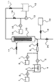
本発明で対象となる造水装置は、例えば、図1に示すように、粉末活性炭スラリーを貯留する活性炭スラリー貯留槽1と、原水に粉末活性炭を供給するスラリー供給ポンプ2と、原水と粉末活性炭を混合撹拌する攪拌機3と、原水を貯留する原水貯留槽4と、原水を供給する原水供給ポンプ5と、凝集剤を貯留する凝集剤貯留槽6と、原水に凝集剤を供給する凝集剤供給ポンプ7と、原水と凝集剤を混合撹拌するスタティックミキサー8と、原水供給時に開となる原水弁9と、原水をろ過するMF/UF膜モジュール10と、膜ろ過時に開となるろ過水弁11と、MF/UF膜モジュール10によって得られた膜ろ過水を貯留するろ過水貯留槽12と、膜ろ過水をMF/UF膜モジュール10に供給して逆洗する逆洗ポンプ13と、逆洗する時に開となる逆洗弁14と、空気洗浄時に膜一次側を満たすことになる水(すなわち原水、あるいは逆圧洗浄水として使用される膜ろ過水)に酸化剤を供給する酸化剤供給ポンプ15と、酸化剤を貯留する酸化剤貯留槽16と、逆圧洗浄や空気洗浄する場合などに開となるエア抜き弁17と、空気をMF/UF膜モジュール10の下方に供給し空気洗浄する場合に開となる空洗弁18と、MF/UF膜モジュール10の空気洗浄の空気供給源であるエアブロワー19と、MF/UF膜モジュール10の膜1次側の水を排出する場合に開となる排水弁20が設けられている。
As shown in FIG. 1, for example, as shown in FIG. 1, the fresh water generator of the present invention includes an activated carbon slurry storage tank 1 that stores powdered activated carbon slurry, a
上述の膜ろ過造水装置において、ろ過工程開始時に吸着剤濃縮層形成工程を行う。吸着剤濃縮層形成工程では、活性炭スラリー貯留槽1に貯留している粉末活性炭スラリーをスラリー供給ポンプ2で原水貯留槽4に供給する。攪拌機3で粉末活性炭と混合撹拌した原水は、原水供給ポンプ5を稼動し原水弁9を開にすることで、MF/UF膜モジュール10内の膜1次側に供給される。さらにろ過水弁11を開にすることでMF/UF膜モジュール10の加圧ろ過を開始する。ろ過水は膜2次側からろ過水弁11を経てろ過水貯留槽12へと移送される。全量ろ過の場合、エア抜き弁17、逆洗弁14、空洗弁18、排水弁20はいずれも閉である。
In the above-mentioned membrane filtration fresh water generator, the adsorbent concentrated layer forming step is performed at the start of the filtration step. In the adsorbent concentrated layer forming step, the powdered activated carbon slurry stored in the activated carbon slurry storage tank 1 is supplied to the raw
吸着剤濃縮層形成工程において、ろ過開始から粉末活性炭のみを添加、混合した原水をろ過していくと、次第に膜表面に粉末活性炭からなる吸着剤濃縮層が形成される。続いて凝集剤供給ポンプ7を稼働して、凝集剤貯留槽6に貯留している凝集剤を粉末活性炭と混合撹拌した原水に供給し、スタティックミキサー8で混合攪拌後、MF/UF膜モジュール10でろ過する。このろ過によって、膜表面に粉末活性炭で形成された吸着剤濃縮層のさらに外側に粉末活性炭および凝集剤で形成された凝集フロック濃縮層が形成され、ろ過工程を実施する。
In the adsorbent concentration layer forming step, when only the powdered activated carbon is added from the start of filtration and the mixed raw water is filtered, an adsorbent concentration layer made of powdered activated carbon is gradually formed on the membrane surface. Subsequently, the
上記ろ過工程開始時の吸着剤濃縮層形成工程において、膜表面に粉末活性炭からなる吸着剤濃縮層を形成する条件としては、原水の吸着剤添加濃度をA(g/m3)、粉末形状の吸着剤のみを添加、混合した原水の膜ろ過流束をB(m3/(m2・d))、粉末形状の吸着剤のみを添加、混合した原水をろ過する時間をC(min)とした場合、吸着剤濃縮層に相当する単位膜面積あたりの吸着剤付着量A×B×C/1440(g/m2)が0.1(g/m2)以上10(g/m2)以下であることが好ましく、より好ましくは0.5(g/m2)以上2(g/m2)以下であるとよい。単位膜面積あたりの吸着剤付着量がこの範囲内になれば、凝集剤供給ポンプ7を稼働して、粉末活性炭および凝集剤で形成された凝集フロック濃縮層を形成し始めればよい。単位膜面積あたりの吸着剤付着量を0.1(g/m2)以上にすることにより、膜を洗浄するとき凝集フロック濃縮層を剥離させる作用を十分に得ることができる。また単位膜面積あたりの吸着剤付着量を10(g/m2)以下にすることにより、ろ過工程における吸着剤濃縮層由来のケークろ過抵抗の上昇を抑制することができる。
In the adsorbent concentration layer forming step at the start of the filtration step, as a condition for forming an adsorbent concentration layer made of powdered activated carbon on the membrane surface, the adsorbent addition concentration of raw water is A (g / m 3 ), B (m 3 / (m 2 · d)) is the membrane filtration flux of the raw water added and mixed with only the adsorbent, and C (min) is the time for filtering the raw water mixed with the powdered adsorbent only. In this case, the adsorbent adhesion amount A × B × C / 1440 (g / m 2 ) per unit membrane area corresponding to the adsorbent concentrated layer is 0.1 (g / m 2 ) or more and 10 (g / m 2 ). Or less, more preferably 0.5 (g / m 2 ) or more and 2 (g / m 2 ) or less. If the adsorbent adhesion amount per unit membrane area falls within this range, the
ろ過工程終了後、膜の洗浄を例えば次のように実施する。 After the filtration step, the membrane is washed, for example, as follows.
まず、原水弁9とろ過水弁11を閉にして、スラリー供給ポンプ2、原水供給ポンプ5、凝集剤供給ポンプ7を停止してMF/UF膜モジュール10のろ過工程を停止する。その後、膜表面に形成された吸着剤濃縮層および吸着剤濃縮層の外側に形成された凝集フロック濃縮層を系外に排出するため、MF/UF膜モジュール10の洗浄を行う。このとき、まず、エア抜き弁17と排水弁20を開く。MF/UF膜モジュール10内の膜1次側の水がMF/UF膜モジュール10下方の排水弁20から膜モジュール系外に排出されると、MF/UF膜モジュール10の水位が下がっていき、膜1次側周囲が気体となった状態となる。ここで、膜1次側とはろ過対象となる原水を供給する側のことであり、膜2次側とは原水を膜でろ過することで得られたろ過水が存在する側のことをいう。MF/UF膜モジュール10内の膜1次側の水は残っていてもかまわないが、少なくとも膜の半分が水面より上となり、気体に触れるようにする。好ましくは、水位が分離膜の上下方向の長さの1/3以下になるまで、より好ましくは膜全体が水面よりも上となり、膜全体が気体に触れるように、水を排出する。
First, the raw water valve 9 and the
その後、エア抜き弁17と排水弁20を開にしたまま逆洗弁14を開にして、逆洗ポンプ13を稼動させることで、ろ過水貯留槽12内の膜ろ過水を用いた逆圧洗浄を行う。このとき、MF/UF膜モジュール10内の逆圧洗浄排水はMF/UF膜モジュール10下方の排水弁20から排出される。従来はろ過工程開始時から粉末活性炭および凝集剤を添加、混合した原水をろ過していたため、粘着質である粉末活性炭と凝集剤が結合した凝集フロック濃縮層が膜表面に直接付着してしまうため、膜1次側に水圧がかからない状態で逆圧洗浄を実施したとしても、凝集フロックが膜表面から剥離しにくかった。これに対し、本発明では、ろ過開始時に粉末形状の吸着剤のみを添加、混合した原水をろ過し、続いて粉末活性炭および凝集剤を添加、混合した原水をろ過して、膜表面に粉末活性炭で形成された吸着剤濃縮層とこの吸着剤濃縮層の外側に粉末活性炭および凝集剤で形成された凝集フロック濃縮層を形成してろ過工程を終了することから、膜表面と凝集フロック濃縮層の間に剥離、分散されやすい吸着剤濃縮層があるため、吸着剤濃縮層が膜表面から剥離するに伴って、凝集フロック濃縮層も剥離し、膜表面をしたたり落ちながら、MF/UF膜モジュール10の下方から排水弁20を経由してそのまま系外に排出される。
Thereafter, the
MF/UF膜モジュール10内の逆圧洗浄排水を排出しながら逆圧洗浄を実施するとき、逆圧洗浄中に継続して膜1次側に水圧がかからないほうが、吸着剤濃縮層およびその外側に位置する凝集フロック濃縮層の剥離効果が上がることから、MF/UF膜モジュール10内の膜一次側の水位が少なくとも分離膜長さの1/3以下を維持するように、逆洗流量を制御することが好ましい。逆洗流量を高くするほど、吸着剤濃縮層およびその外側に位置する凝集フロック濃縮層の剥離効果が上がるものの、MF/UF膜モジュール10の下方から自重で排出される排水流量はMF/UF膜モジュール10の排水口の大きさによって限界があり、膜一次側の水位が上昇して膜一次側に水圧がかかってしまうことがある。よってMF/UF膜モジュール10の構造に応じて逆洗流量を適宜制御することが好ましい。
When back pressure cleaning is carried out while discharging the back pressure cleaning waste water in the MF /
その後、排水弁20を閉にして、MF/UF膜モジュール10内の膜一次側に水を満たし、空洗弁18を開、エアブロワー19を稼動することで、MF/UF膜モジュール10の下方から気体を供給し、空気洗浄を行う。
Thereafter, the
MF/UF膜モジュール10内の膜一次側に水を満たす方法としては、原水弁9を開にして原水供給ポンプ5を稼動して原水を供給してもよいし、逆洗弁14を開にして逆洗ポンプ13を稼動して膜ろ過水を逆圧洗浄水として供給してもよい。この時供給する原水あるいは膜ろ過水(すなわち、空気洗浄時にMF/UF膜モジュール10内の膜一次側を満たすことになる水)には酸化剤供給ポンプ15を稼動して酸化剤を添加したほうが、膜表面や膜細孔内に蓄積していた有機物を分解除去する効果があるので好ましい。従来の物理洗浄では、MF/UF膜モジュール10内の凝集フロック濃縮層が膜表面から充分に剥離できなかったため、原水や膜ろ過水に添加された酸化剤は膜表面や膜細孔内に蓄積していた有機物を分解除去する前に粉末活性炭にほとんど消費されてしまったのに対し、本発明では酸化剤を最大限活用することが可能である。
As a method for filling the primary side of the membrane in the MF /
空気洗浄は、(a)予めMF/UF膜モジュール10内の膜一次側が水で満たされた状態で開始しても、(b)MF/UF膜モジュール10内の膜一次側に水を供給しながら(すなわち空気洗浄中にMF/UF膜モジュール10内に原水を供給したり、逆圧洗浄を行ったりしながら)行ってもよい。ただし、水を供給しながら空気洗浄を行うほうが、洗浄効果が高まるので好ましい。
Even if the air cleaning starts (a) the membrane primary side in the MF /
その後、空洗弁18を閉にするとともにエアブロワー19を停止して空気洗浄を終了する。なお、空気洗浄中にMF/UF膜モジュール10内に原水を供給したり、逆圧洗浄を継続している場合には、原水弁9、逆洗弁14も閉にし、原水供給ポンプ5、逆洗ポンプ13、酸化剤供給ポンプ15も停止して、原水供給や逆圧洗浄も終了したほうが好ましい。
Thereafter, the
次いで、排水弁20を開にすることで、膜面や膜細孔内から剥離してMF/UF膜モジュール10内で浮遊している懸濁物質を系外に排出する。
Next, the
排水終了後には、排水弁20を閉、原水弁9を開とし、原水供給ポンプ5を稼動して給水を行い、MF/UF膜モジュール10の膜1次側を満水にする。その後、エア抜き弁17を閉、ろ過水弁11を開とすれば、MF/UF膜モジュール10はろ過工程に戻り、上記工程を吸着剤濃縮層形成工程から繰り返すことで造水を継続することができる
本発明の洗浄方法はろ過工程終了後に毎回行っても構わないし、別の洗浄方法と組み合わせて時々行ってもかまわない。逆圧洗浄を実施する前にMF/UF膜モジュール10下方の排水弁20から排出された膜一次側の水や、逆圧洗浄を実施したときのMF/UF膜モジュール10下方の排水弁20から排出された逆圧洗浄排水や、空気洗浄の実施中あるいは実施後にMF/UF膜モジュール10の上部のエア抜き弁17やMF/UF膜モジュール10下方の排水弁20から排出された空気洗浄排水を沈殿分離して、その上澄水を原水として再使用するほうが、水回収率が高くなるので好ましい。沈殿分離の他に、凝集沈殿分離、加圧浮上分離、遠心分離、砂ろ過分離、精密ろ過膜/限外ろ過膜のろ過分離、ろ布のろ過分離、繊維状フィルターのろ過分離、カートリッジフィルターのろ過分離、ディスクフィルター分離、フィルタープレス、ベルトプレス、真空脱水、多重円板脱水などの手段が選択できるが、排水に含まれる懸濁物質は凝集フロックが主体であり、沈降性が高いことから沈殿分離が適している。また、設備コスト、処理コストなどの観点からも沈殿分離が好ましい。
After drainage is completed, the
本発明における粉末形状の吸着剤とは、粉末活性炭、珪藻土、ベントナイト、カオリン、モンモリロナイト、ゼオライト、セリウム系吸着剤、二酸化マンガン、イオン交換樹脂等が挙げられるが、吸着能力の観点から原水に色度成分や臭気物質等を多く含有している場合には粉末活性炭が好ましく採用され、原水に油分を多く含有している場合には珪藻土、ベントナイト、カオリン、モンモリロナイト等の天然由来の粘土鉱物が好ましく採用され、原水にヒ素、ホウ素、フッ素を多く含有している場合には、セリウム系吸着剤、二酸化マンガン、イオン交換樹脂が好ましく採用される。 Examples of the powder-shaped adsorbent in the present invention include powdered activated carbon, diatomaceous earth, bentonite, kaolin, montmorillonite, zeolite, cerium-based adsorbent, manganese dioxide, ion exchange resin, etc. Powdered activated carbon is preferably used when it contains a large amount of ingredients and odorous substances, and naturally derived clay minerals such as diatomaceous earth, bentonite, kaolin, and montmorillonite are preferably used when the raw water contains a large amount of oil. When the raw water contains a large amount of arsenic, boron, and fluorine, cerium-based adsorbent, manganese dioxide, and ion exchange resin are preferably employed.
本発明における粉末形状の吸着剤の粒子径は、粉末活性炭の場合、JIS K 1474:2007に記載されている通り、150μm未満のものを粉末形状と定義する。その他の粉末形状の吸着剤についても同様に150μm未満のものを粉末形状と定義する。また、粒子径は小さければ小さいほど比表面積が大きくなり、吸着能が高くなるので好ましい。但し、膜ろ過水に混入しないようMF/UF膜モジュール10の分離膜の孔径より大きくする必要がある。
In the case of powdered activated carbon, the particle size of the powder-shaped adsorbent in the present invention is defined as a powder shape of less than 150 μm, as described in JIS K 1474: 2007. Similarly, other powder-shaped adsorbents are defined as those having a powder shape of less than 150 μm. Further, the smaller the particle size, the larger the specific surface area and the higher the adsorption ability, which is preferable. However, it is necessary to make it larger than the pore diameter of the separation membrane of the MF /
粉末活性炭の原料としては、ヤシ殻やおが屑などの木質系や泥炭、亜炭、瀝青炭などの石炭系のいずれでも構わない。 The raw material for the powdered activated carbon may be any of woody materials such as coconut shells and sawdust, and coal-based materials such as peat, lignite and bituminous coal.
本発明における凝集剤とは膜ろ過中の高分子有機物濃度を低減する効果がある。有機系凝集剤としては、ジメチルアミン系やポリアクリルアミド系のカチオン高分子凝集剤、などを使用することができる。一方、無機系凝集剤としては、ポリ塩化アルミニウムやポリ硫酸アルミニウム、塩化第二鉄、ポリ硫酸第二鉄、硫酸第二鉄、ポリシリカ鉄等を使用できる。 The flocculant in the present invention has an effect of reducing the concentration of high molecular organic substances during membrane filtration. Examples of organic flocculants include dimethylamine-based and polyacrylamide-based cationic polymer flocculants. On the other hand, polyaluminum chloride, polyaluminum sulfate, ferric chloride, ferric sulfate, ferric sulfate, polysilica iron, etc. can be used as the inorganic flocculant.
MF/UF膜モジュール10としては、外圧式でも内圧式であっても差し支えはないが、前処理の簡便さの観点から外圧式が好ましい。また膜ろ過方式としては全量ろ過型モジュールでもクロスフローろ過型モジュールであっても差し支えはないが、エネルギー消費量が少ないという点から全量ろ過型モジュールが好ましい。さらに加圧型モジュールであっても浸漬型モジュールであっても差し支えはないが、高流束が可能であるという点から加圧型モジュールが好ましい。
The MF /
MF/UF膜モジュール10で使用される分離膜としては、多孔質であれば特に限定しないが、所望の処理水の水質や水量によって、MF膜(精密ろ過膜)を用いたり、UF膜(限外ろ過膜)を用いたり、あるいは両者を併用したりする。例えば、濁質成分、大腸菌、クリプトスポリジウム等を除去したい場合はMF膜でもUF膜のどちらを用いても構わないが、ウィルスや高分子有機物等も除去したい場合は、UF膜を用いるのが好ましい。
The separation membrane used in the MF /
分離膜の形状としては、中空糸膜、平膜、管状膜等があるが、いずれでも構わない。 Examples of the shape of the separation membrane include a hollow fiber membrane, a flat membrane, and a tubular membrane, and any of them may be used.
分離膜の材質としては、ポリエチレン、ポリプロピレン、ポリアクリロニトリル、エチレン−テトラフルオロエチレン共重合体、ポリクロロトリフルオロエチレン、ポリテトラフルオロエチレン、ポリビニルフルオライド、テトラフルオロエチレン−ヘキサフルオロプロピレン共重合体、テトラフルオロエチレン−パーフルオロアルキルビニルエーテル共重合体、およびクロロトリフルオロエチレン−エチレン共重合体、ポリフッ化ビニリデン、ポリスルホン、酢酸セルロース、ポリビニルアルコールおよびポリエーテルスルホン等からなる群から選ばれる少なくとも1種類を含んでいると好ましく、さらに膜強度や耐薬品性の点からはポリフッ化ビニリデン(PVDF)がより好ましく、親水性が高く耐汚れ性が強いという点からはポリアクリロニトリルがより好ましい。なお、上述した有機高分子樹脂製の分離膜は、粉末活性炭、ベントナイト、カオリンなどの吸着剤よりも硬度が低いため、本発明の分離膜モジュールの洗浄方法において、好ましく使用することができる。 The material of the separation membrane is polyethylene, polypropylene, polyacrylonitrile, ethylene-tetrafluoroethylene copolymer, polychlorotrifluoroethylene, polytetrafluoroethylene, polyvinyl fluoride, tetrafluoroethylene-hexafluoropropylene copolymer, tetra Including at least one selected from the group consisting of a fluoroethylene-perfluoroalkyl vinyl ether copolymer, and a chlorotrifluoroethylene-ethylene copolymer, polyvinylidene fluoride, polysulfone, cellulose acetate, polyvinyl alcohol, and polyethersulfone. Polyvinylidene fluoride (PVDF) is more preferable from the viewpoint of film strength and chemical resistance, and from the viewpoint of high hydrophilicity and strong stain resistance. Rironitoriru is more preferable. In addition, since the separation membrane made of the organic polymer resin described above has lower hardness than the adsorbent such as powdered activated carbon, bentonite and kaolin, it can be preferably used in the method for cleaning the separation membrane module of the present invention.
ろ過運転の制御方法としては、定流量ろ過であっても定圧ろ過であってもよいが、一定の処理水量が得られ、また、全体の制御が容易であるという点から定流量ろ過が好ましい。 The control method for the filtration operation may be constant flow filtration or constant pressure filtration, but constant flow filtration is preferred from the viewpoint that a constant amount of treated water can be obtained and the overall control is easy.
以上の本発明によれば、凝集フロック濃縮層由来のケークろ過抵抗を抑制し、長期間にわたる低い膜ろ過差圧での安定運転が可能である。ただし、凝集フロック濃縮層や粉末活性炭で吸着しきれず、膜表面に付着した原水由来の有機物を完全に除去することは難しく、酸化剤によって酸化された鉄やマンガン等が膜面に徐々に析出したりすることがある。そのため、膜ろ過差圧がMF/UF膜モジュール10の耐圧限界近くまで到達した場合には、高濃度の薬品洗浄を実施することが好ましい。
According to the present invention described above, the cake filtration resistance derived from the aggregated floc concentrated layer can be suppressed, and stable operation with a low membrane filtration differential pressure over a long period of time is possible. However, it cannot be completely adsorbed by the coagulated floc-concentrated layer or powdered activated carbon, and it is difficult to completely remove organic substances derived from raw water adhering to the membrane surface, and iron, manganese, etc. oxidized by the oxidizing agent gradually precipitate on the membrane surface. Sometimes. Therefore, when the membrane filtration differential pressure reaches close to the pressure limit of the MF /
該洗浄に用いる薬品としては、膜が劣化しない程度の濃度および保持時間を適宜設定した上で選択することができるが、次亜塩素酸ナトリウム、二酸化塩素、過酸化水素、オゾン等を少なくとも1つ含有した方が、有機物に対して洗浄効果が高くなるので好ましい。また、塩酸、硫酸、硝酸、クエン酸、シュウ酸等を少なくとも1つ含有した方が、アルミニウム、鉄、マンガン等に対して洗浄効果が高くなるので好ましい。 The chemical used for the cleaning can be selected after appropriately setting the concentration and holding time to such an extent that the film does not deteriorate. At least one of sodium hypochlorite, chlorine dioxide, hydrogen peroxide, ozone and the like can be selected. It is preferable to contain it because the cleaning effect on the organic matter is increased. In addition, it is preferable to contain at least one of hydrochloric acid, sulfuric acid, nitric acid, citric acid, oxalic acid and the like because the cleaning effect on aluminum, iron, manganese and the like is increased.
(実施例1)
図1に示す装置にて、MF/UF膜モジュール10には東レ(株)製の外圧式PVDF限外中空糸膜モジュールHFU−2020(膜面積72m2)を1本使用し、原水弁9とろ過水弁11を開にして、スラリー供給ポンプ2と原水供給ポンプ5を稼動して、原水貯留槽4内で粉末活性炭の添加濃度を30g/m3に調整した河川水を用いて膜ろ過流束1.5m3/(m2・d)の定流量ろ過を開始した。定流量ろ過開始から5min後には凝集剤供給ポンプ7を稼働して、ポリ塩化アルミニウムの添加濃度を1g−Al/m3と粉末活性炭の添加濃度を30g/m3に調整した河川水を膜ろ過流束1.5m3/(m2・d)で25min定流量ろ過し、トータル30minの定流量ろ過を実施した。そのときの吸着剤濃縮層に相当する単位膜面積あたりの粉末活性炭付着量は30×1.5×5/1440=0.156g/m2であった。定流量ろ過開始から30min後に原水弁9とろ過水弁11を閉にして、スラリー供給ポンプ2、原水供給ポンプ5、凝集剤供給ポンプ7を停止してMF/UF膜モジュール10のろ過工程を停止した後、エア抜き弁17と排水弁20を開にして、MF/UF膜モジュール10内の膜1次側の水を全量排出した。その後、エア抜き弁17と排水弁20を開にしたまま、逆洗弁14を開、逆洗ポンプ13を稼動し、流束2m3/(m2・d)の逆圧洗浄を1min実施した。その後、逆洗弁14と排水弁20を閉にして、逆洗ポンプ13を停止すると同時に原水弁9と空洗弁18を開にして、原水供給ポンプ5とエアブロワー19を稼動して、MF/UF膜モジュール10の膜1次側に75L/minの原水を供給しながらエア流量100L/minの空気を供給する空気洗浄を1min実施した。その後、原水弁9と空洗弁18を閉じ、原水供給ポンプ5とエアブロワー19を停止すると同時に、排水弁20を開け、MF/UF膜モジュール10内の膜1次側の水を全量排出した。その後、排水弁20を閉じると同時に、原水弁9を開き、スラリー供給ポンプ2と原水供給ポンプ5を稼動して、MF/UF膜モジュール10内の膜1次側を、粉末活性炭を含有した原水で満たした後、ろ過水弁11を開にして、エア抜き弁17を閉にして、ろ過工程に戻り、上記工程を繰り返していった。
Example 1
In the apparatus shown in FIG. 1, one external pressure PVDF ultra-hollow fiber membrane module HFU-2020 (membrane area 72 m 2 ) manufactured by Toray Industries, Inc. is used for the MF /
その結果、MF/UF膜モジュール10の膜ろ過差圧は運転開始直後18kPaに対し、4ヶ月後も43kPaと安定運転を行うことができた。
As a result, the membrane filtration differential pressure of the MF /
(実施例2)
図1に示す装置にて、MF/UF膜モジュール10には東レ(株)製の外圧式PVDF限外中空糸膜モジュールHFU−2020(膜面積72m2)を1本使用し、原水弁9とろ過水弁11を開にして、スラリー供給ポンプ2と原水供給ポンプ5を稼動して、原水貯留槽4内でベントナイトの添加濃度を30g/m3に調整した工場排水を用いて膜ろ過流束1m3/(m2・d)の定流量ろ過を開始した。定流量ろ過開始から5min後には凝集剤供給ポンプ7を稼働して、ポリ塩化アルミニウムの添加濃度を2g−Al/m3とベントナイトの添加濃度を30g/m3に調整した工場排水を膜ろ過流束1m3/(m2・d)で25min定流量ろ過し、トータル30minの定流量ろ過を実施した。そのときの吸着剤濃縮層に相当する単位膜面積あたりのベントナイト付着量は30×1×5/1440=0.104g/m2であった。定流量ろ過開始から30min後に原水弁9とろ過水弁11を閉にして、スラリー供給ポンプ2、原水供給ポンプ5、凝集剤供給ポンプ7を停止してMF/UF膜モジュール10のろ過工程を停止した後、エア抜き弁17と排水弁20を開にして、MF/UF膜モジュール10内の膜1次側の水を全量排出した。その後、エア抜き弁17と排水弁20を開にしたまま、逆洗弁14を開、逆洗ポンプ13を稼動し、流束1.5m3/(m2・d)の逆圧洗浄を1min実施した。その後、逆洗弁14と排水弁20を閉にして、逆洗ポンプ13を停止すると同時に原水弁9と空洗弁18を開にして、原水供給ポンプ5とエアブロワー19を稼動して、MF/UF膜モジュール10の膜1次側に50L/minの原水を供給しながらエア流量100L/minの空気を供給する空気洗浄を1min実施した。その後、原水弁9と空洗弁18を閉じ、原水供給ポンプ5とエアブロワー19を停止すると同時に、排水弁20を開け、MF/UF膜モジュール10内の膜1次側の水を全量排出した。その後、排水弁20を閉じると同時に、原水弁9を開き、スラリー供給ポンプ2と原水供給ポンプ5を稼動して、MF/UF膜モジュール10内の膜1次側を、粉末活性炭を含有した原水で満たした後、ろ過水弁11を開にして、エア抜き弁17を閉にして、ろ過工程に戻り、上記工程を繰り返していった。
(Example 2)
In the apparatus shown in FIG. 1, one external pressure PVDF ultra-hollow fiber membrane module HFU-2020 (membrane area 72 m 2 ) manufactured by Toray Industries, Inc. is used for the MF /
その結果、MF/UF膜モジュール10の膜ろ過差圧は運転開始直後11kPaに対し、4ヶ月後も29kPaと安定運転を行うことができた。
As a result, the membrane filtration differential pressure of the MF /
(比較例1)
図1に示す装置にて、MF/UF膜モジュール10には東レ(株)製の外圧式PVDF限外中空糸膜モジュールHFU−2020(膜面積72m2)を1本使用し、原水弁9とろ過水弁11を開いて、スラリー供給ポンプ2と原水供給ポンプ5と凝集剤供給ポンプ7を稼動して、ポリ塩化アルミニウムの添加濃度を1g−Al/m3と粉末活性炭の添加濃度を30g/m3に調整した河川水を膜ろ過流束1.5m3/(m2・d)で30min定流量ろ過し、吸着剤濃縮層を形成せず凝集フロック濃縮層のみを形成した以外は実施例1と全く同じにした。
(Comparative Example 1)
In the apparatus shown in FIG. 1, one external pressure PVDF ultra-hollow fiber membrane module HFU-2020 (membrane area 72 m 2 ) manufactured by Toray Industries, Inc. is used for the MF /
その結果、MF/UF膜モジュール10の膜ろ過差圧は運転開始直後18kPaに対し、83日後には120kPaに急上昇した。
As a result, the membrane filtration differential pressure of the MF /
(比較例2)
図1に示す装置にて、MF/UF膜モジュール10には東レ(株)製の外圧式PVDF限外中空糸膜モジュールHFU−2020(膜面積72m2)を1本使用し、原水弁9とろ過水弁11を開いて、スラリー供給ポンプ2と原水供給ポンプ5と凝集剤供給ポンプ7を稼動して、ポリ塩化アルミニウムの添加濃度を2g−Al/m3とベントナイトの添加濃度を30g/m3に調整した工場排水を膜ろ過流束1m3/(m2・d)で30min定流量ろ過し、吸着剤濃縮層を形成せず凝集フロック濃縮層のみを形成した以外は実施例1と全く同じにした。
(Comparative Example 2)
In the apparatus shown in FIG. 1, one external pressure PVDF ultra-hollow fiber membrane module HFU-2020 (membrane area 72 m 2 ) manufactured by Toray Industries, Inc. is used for the MF /
その結果、MF/UF膜モジュール10の膜ろ過差圧は運転開始直後11kPaに対し、98日後には120kPaに急上昇した。
As a result, the membrane filtration differential pressure of the MF /
1 活性炭スラリー貯留槽
2 スラリー供給ポンプ
3 攪拌機
4 原水貯留槽
5 原水供給ポンプ
6 凝集剤貯留槽
7 凝集剤供給ポンプ
8 スタティックミキサー
9 原水弁
10 MF/UF膜モジュール
11 ろ過水弁
12 ろ過水貯留槽
13 逆洗ポンプ
14 逆洗弁
15 酸化剤供給ポンプ
16 酸化剤貯留槽
17 エア抜き弁
18 空洗弁
19 エアブロワー
20 排水弁
DESCRIPTION OF SYMBOLS 1 Activated carbon
Claims (9)
(a)分離膜モジュール内の膜一次側を水で満たして空気洗浄を行う工程
(b)分離膜モジュール内の膜一次側に水を給水しながら空気洗浄を行う工程 In the method of cleaning the separation membrane module after adding powder-form adsorbent and flocculant and filtering the mixed raw water, only powder-form adsorbent is added at the start of filtration, and the adsorbent concentrated layer is formed to filter the mixed raw water After performing the process, adding powder-form adsorbent and flocculant, filtering the mixed raw water and finishing the filtration process, the water on the primary side of the membrane in the separation membrane module is discharged out of the system, , Discharge the backwash water in the separation membrane module while performing backwashing, then perform one of the following steps, and then discharge the water on the primary side of the separation membrane module out of the system. A method for cleaning the separation membrane module.
(A) Step of performing air cleaning by filling the membrane primary side in the separation membrane module with water (b) Step of performing air cleaning while supplying water to the membrane primary side in the separation membrane module
Priority Applications (3)
| Application Number | Priority Date | Filing Date | Title |
|---|---|---|---|
| JP2012031559A JP2015085206A (en) | 2012-02-16 | 2012-02-16 | Separation membrane module cleaning method |
| PCT/JP2013/052545 WO2013121921A1 (en) | 2012-02-16 | 2013-02-05 | Method for cleaning separation-membrane module |
| TW102105051A TW201338851A (en) | 2012-02-16 | 2013-02-08 | Cleaning method for module of separation membranes |
Applications Claiming Priority (1)
| Application Number | Priority Date | Filing Date | Title |
|---|---|---|---|
| JP2012031559A JP2015085206A (en) | 2012-02-16 | 2012-02-16 | Separation membrane module cleaning method |
Publications (1)
| Publication Number | Publication Date |
|---|---|
| JP2015085206A true JP2015085206A (en) | 2015-05-07 |
Family
ID=48984035
Family Applications (1)
| Application Number | Title | Priority Date | Filing Date |
|---|---|---|---|
| JP2012031559A Pending JP2015085206A (en) | 2012-02-16 | 2012-02-16 | Separation membrane module cleaning method |
Country Status (3)
| Country | Link |
|---|---|
| JP (1) | JP2015085206A (en) |
| TW (1) | TW201338851A (en) |
| WO (1) | WO2013121921A1 (en) |
Cited By (3)
| Publication number | Priority date | Publication date | Assignee | Title |
|---|---|---|---|---|
| JP2017202439A (en) * | 2016-05-10 | 2017-11-16 | オルガノ株式会社 | Waste water recovery system, and waste water recovery method |
| DE102016125482A1 (en) * | 2016-12-22 | 2018-06-28 | Strecker Wassertechnik Gmbh | Method and device for filtering a contaminant containing raw fluid by means of at least one membrane filter unit and a use thereof |
| CN110921780A (en) * | 2019-11-22 | 2020-03-27 | 河海大学 | Purification system and purification method for wastewater containing surfactant |
Families Citing this family (1)
| Publication number | Priority date | Publication date | Assignee | Title |
|---|---|---|---|---|
| CN106698593A (en) * | 2016-09-13 | 2017-05-24 | 龙吉林 | Method for refreshing water of water tank of water purifier |
Family Cites Families (7)
| Publication number | Priority date | Publication date | Assignee | Title |
|---|---|---|---|---|
| JPH04114722A (en) * | 1990-09-04 | 1992-04-15 | Asahi Chem Ind Co Ltd | Filtering method for liquid containing organic substances |
| JPH05212374A (en) * | 1992-01-31 | 1993-08-24 | Toshiba Corp | Surfactant removal device |
| JPH0957292A (en) * | 1995-08-24 | 1997-03-04 | Mitsubishi Rayon Co Ltd | Waste water treating device |
| JP3142792B2 (en) * | 1997-03-14 | 2001-03-07 | 川崎重工業株式会社 | Wastewater treatment method using carbon-based adsorbent |
| JP2006223921A (en) * | 2005-02-15 | 2006-08-31 | Toray Ind Inc | Water treatment method |
| JP2009101981A (en) * | 2007-10-02 | 2009-05-14 | Osumo:Kk | Car washing method and device |
| JP4968413B2 (en) * | 2010-03-30 | 2012-07-04 | 東レ株式会社 | Separation membrane module cleaning method and fresh water generation method |
-
2012
- 2012-02-16 JP JP2012031559A patent/JP2015085206A/en active Pending
-
2013
- 2013-02-05 WO PCT/JP2013/052545 patent/WO2013121921A1/en active Application Filing
- 2013-02-08 TW TW102105051A patent/TW201338851A/en unknown
Cited By (3)
| Publication number | Priority date | Publication date | Assignee | Title |
|---|---|---|---|---|
| JP2017202439A (en) * | 2016-05-10 | 2017-11-16 | オルガノ株式会社 | Waste water recovery system, and waste water recovery method |
| DE102016125482A1 (en) * | 2016-12-22 | 2018-06-28 | Strecker Wassertechnik Gmbh | Method and device for filtering a contaminant containing raw fluid by means of at least one membrane filter unit and a use thereof |
| CN110921780A (en) * | 2019-11-22 | 2020-03-27 | 河海大学 | Purification system and purification method for wastewater containing surfactant |
Also Published As
| Publication number | Publication date |
|---|---|
| WO2013121921A1 (en) | 2013-08-22 |
| TW201338851A (en) | 2013-10-01 |
Similar Documents
| Publication | Publication Date | Title |
|---|---|---|
| JP4968413B2 (en) | Separation membrane module cleaning method and fresh water generation method | |
| JP5954182B2 (en) | Cleaning method for separation membrane module | |
| CN102260009B (en) | Method for processing dye wastewater | |
| CN105384316B (en) | A kind of processing method of the fluorine-containing nitrogen-containing wastewater of electronics industry | |
| JP3698093B2 (en) | Water treatment method and water treatment apparatus | |
| WO2013111826A1 (en) | Desalination method and desalination device | |
| JP4309633B2 (en) | Water treatment method | |
| CN104108830A (en) | Novel recycled water advanced treatment and recycling system | |
| CN105073652A (en) | Fresh water production process | |
| WO2013121921A1 (en) | Method for cleaning separation-membrane module | |
| JP2009006209A (en) | Cleaning method of hollow fiber membrane module | |
| JP2013202481A (en) | Cleaning method of separation membrane module | |
| JP2007289847A (en) | Raw tap water purification method and its apparatus | |
| CN104418451B (en) | A kind of processing method of reverse osmosis concentrated water | |
| WO2017159303A1 (en) | Method for treating waste water having high hardness | |
| JP2012086120A (en) | Method for washing immersion type membrane module with chemical | |
| WO2013047466A1 (en) | Membrane module cleaning method | |
| WO2012057176A1 (en) | Water-treatment method and desalinization method | |
| JP2002370089A (en) | Washing wastewater cleaning system | |
| JP2001239136A (en) | Treating system and operating method therefor | |
| CN107892409A (en) | A kind of efficient reuse method of eider down industrial wastewater and its device | |
| JP2005270906A (en) | Membrane-washing method and membrane separation device | |
| JP5174548B2 (en) | Operation method of combined filtration equipment | |
| JP2005279618A (en) | Liquid chemical cleaning method | |
| KR20100113312A (en) | Water purification device and water purification method |