JP2015073721A - Game machine - Google Patents
Game machine Download PDFInfo
- Publication number
- JP2015073721A JP2015073721A JP2013211648A JP2013211648A JP2015073721A JP 2015073721 A JP2015073721 A JP 2015073721A JP 2013211648 A JP2013211648 A JP 2013211648A JP 2013211648 A JP2013211648 A JP 2013211648A JP 2015073721 A JP2015073721 A JP 2015073721A
- Authority
- JP
- Japan
- Prior art keywords
- display
- special symbol
- stage
- notice
- jackpot
- Prior art date
- Legal status (The legal status is an assumption and is not a legal conclusion. Google has not performed a legal analysis and makes no representation as to the accuracy of the status listed.)
- Pending
Links
- 238000005034 decoration Methods 0.000 claims abstract description 36
- 238000000034 method Methods 0.000 description 192
- 230000008569 process Effects 0.000 description 190
- 230000008859 change Effects 0.000 description 37
- 238000012545 processing Methods 0.000 description 36
- 238000001514 detection method Methods 0.000 description 35
- 230000000694 effects Effects 0.000 description 16
- 238000003860 storage Methods 0.000 description 11
- 238000012544 monitoring process Methods 0.000 description 7
- 238000004458 analytical method Methods 0.000 description 5
- 238000012790 confirmation Methods 0.000 description 5
- 239000003086 colorant Substances 0.000 description 4
- 238000004519 manufacturing process Methods 0.000 description 4
- 239000004973 liquid crystal related substance Substances 0.000 description 3
- 239000000758 substrate Substances 0.000 description 3
- 230000005540 biological transmission Effects 0.000 description 2
- 238000004364 calculation method Methods 0.000 description 2
- 238000013461 design Methods 0.000 description 2
- 238000010586 diagram Methods 0.000 description 2
- 239000011159 matrix material Substances 0.000 description 2
- 230000001151 other effect Effects 0.000 description 2
- 230000005236 sound signal Effects 0.000 description 2
- 241001465754 Metazoa Species 0.000 description 1
- 241000269851 Sarda sarda Species 0.000 description 1
- 230000005856 abnormality Effects 0.000 description 1
- 230000008901 benefit Effects 0.000 description 1
- 238000006243 chemical reaction Methods 0.000 description 1
- 238000013500 data storage Methods 0.000 description 1
- 238000006073 displacement reaction Methods 0.000 description 1
- 239000011521 glass Substances 0.000 description 1
- 238000013508 migration Methods 0.000 description 1
- 230000005012 migration Effects 0.000 description 1
- 238000002360 preparation method Methods 0.000 description 1
- 230000004044 response Effects 0.000 description 1
- 238000004904 shortening Methods 0.000 description 1
- 230000001360 synchronised effect Effects 0.000 description 1
Images


Landscapes
- Display Devices Of Pinball Game Machines (AREA)
Abstract
Description
本発明は、当否判定手段の結果を示唆する予告を段階的に表示する遊技機に関する。 The present invention relates to a gaming machine that displays step-by-step notices that suggest the result of the determination unit.
従来、パチンコ遊技機等においては、例えば、キャラクターを段階的に表示するステップアップ予告と称する表示を行うことで、遊技の当否判定結果を示唆する機種があった。 Conventionally, in a pachinko gaming machine or the like, for example, there is a model that suggests a game success / failure determination result by displaying a step-up notice that displays characters step by step.
しかしながら、キャラクターを段階的に表示するステップアップ予告を行う従来の遊技機にあっては、例えばステップアップ予告と同時に行われる演出の一部などが邪魔して現在何れの段階にあるのかを遊技者が認識し難い場合があった。 However, in a conventional gaming machine that performs step-up notices that display characters step by step, for example, the player can determine which stage is currently in the middle due to a part of the effects performed at the same time as the step-up notice. There were cases where it was difficult to recognize.
本発明は、前記の点に鑑みなされたものであって、段階的にキャラクターを表示させる段階的表示予告を行う際に、現在何れの段階にあるのかを遊技者が認識し易い遊技機の提供を目的とする。 The present invention has been made in view of the above points, and provides a gaming machine in which a player can easily recognize which stage the player is currently in when performing a step-by-step display notice for displaying characters step by step. With the goal.
請求項1の発明は、遊技の当否を判定する当否判定手段と、前記当否判定手段の判定結果を示唆する予告を表示する表示手段と、を備えた遊技機において、前記予告には、段階的にキャラクターを表示させる段階的表示予告を有し、前記段階的表示予告を行うか否かを決定する予告決定手段と、前記予告決定手段で前記段階的表示予告を行うと決定された場合に前記段階的表示予告を前記表示手段で表示する制御を行う制御手段と、を備え、前記制御手段は、前記段階的表示予告の段階数を前記当否判定手段の判定結果に基づいて選択する第1制御手段と、複数のキャラクターの各々に、出現する段階を割り付ける第2制御手段と、前記複数のキャラクターを前記第2制御手段で割り付けられた段階で出現するように制御して前記表示手段に表示する第3制御手段と、段階を示す数を認識できる少なくとも2つの表示態様で前記各々のキャラクターに付与して前記表示手段に表示する第4制御手段と、を備え、前記複数のキャラクターを前記第2制御手段で割り付けられた段階で前記第3制御手段によって前記表示手段に出現させる毎に、前記第4制御手段によって付与された前記少なくとも2つの表示態様を、前記第2制御手段によって割り付けられた段階に合わせて変更することを特徴とする。 According to the first aspect of the present invention, in the gaming machine provided with the success / failure determination means for determining whether or not the game is successful and the display means for displaying the advance notice indicating the determination result of the success / failure determination means, Has a step-by-step display notice for displaying a character, and a notice-deciding means for deciding whether or not to perform the step-by-step display notice, and when the step-by-step display notice is decided by the notice decision means, Control means for controlling the display means to display a stepwise display notice, wherein the control means selects the number of stages of the stepwise display notice based on the determination result of the validity determination means. Means, second control means for assigning the stage of appearance to each of the plurality of characters, and controlling the display means to appear so that the plurality of characters appear at the stage assigned by the second control means. 3rd control means to show, and 4th control means to give to each said character in at least two display modes which can recognize the number which shows a stage, and to display on said display means, The plurality of characters are mentioned above Each time the third control means causes the display means to appear at the stage assigned by the second control means, the at least two display modes given by the fourth control means are assigned by the second control means. It is characterized by changing according to the stage.
請求項2の発明は、請求項1において、前記キャラクターの一部に前記少なくとも2つの表示態様を表示することを特徴とする。 According to a second aspect of the present invention, in the first aspect, the at least two display modes are displayed on a part of the character.
請求項3の発明は、請求項2において、前記少なくとも2つの表示態様のうち少なくとも1つは数字で表示されることを特徴とする。 According to a third aspect of the present invention, in the second aspect of the present invention, at least one of the at least two display modes is displayed as a number.
請求項4の発明は、請求項1から3の何れか一項において、前記キャラクターの少なくとも一部は装飾態様で表示され、前記複数の表示態様の少なくとも1つの表示態様は、段階数と同等の数分の装飾部を前記キャラクターの装飾態様部分に有するものであって、段階が変化する毎に前記制御手段によって前記段階に応じた数の前記装飾部を変化させると共に前記装飾態様の一部として表示することを特徴とする。 According to a fourth aspect of the present invention, in any one of the first to third aspects, at least a part of the character is displayed in a decoration mode, and at least one display mode of the plurality of display modes is equivalent to the number of steps. The decoration portion of the character has several minutes of decoration, and each time the stage changes, the control means changes the number of the decoration parts according to the stage and as a part of the decoration aspect It is characterized by displaying.
請求項1の発明によれば、複数のキャラクターを段階的に表示する際に、少なくとも2つの表示態様によって段階を示すことができるため、遊技者に何れの段階にあるのかを認識し易くすることが可能である。 According to the first aspect of the present invention, when a plurality of characters are displayed step by step, the step can be indicated by at least two display modes, so that it is easy for the player to recognize which step the player is in. Is possible.
請求項2の発明によれば、キャラクターの一部に少なくとも2つの表示態様を表示するため、キャラクターが何れの段階を示しているのかを遊技者に認識させることが可能である。
According to the invention of
請求項3の発明によれば、少なくとも2つの表示態様のうち少なくとも1つは数字で表示されるため、現在の段階を遊技者に認識させることが可能である。
According to the invention of
請求項4の発明によれば、キャラクターの装飾に違和感が残る虞を低減し、かつ現在の段階を遊技者に認識させることが可能である。 According to the fourth aspect of the present invention, it is possible to reduce the possibility that a sense of incongruity remains in the decoration of the character and to make the player recognize the current stage.
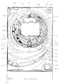
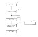
以下、添付の図面に基づき本発明の実施例を説明する。図1に示す遊技機1は、遊技媒体として遊技球を用いるパチンコ遊技機であって、遊技盤2の縁に外側誘導レール3及び内側誘導レール4が略円形に配置され、前記外側誘導レール3及び内側誘導レール4によって区画された遊技領域6が前記遊技盤2上に設けられている。前記遊技領域6には遊技球を誘導する誘導釘Rが遊技盤2の表面に設けられている。また、遊技機1の前面側には、装飾ランプ等からなるランプ装置35、発射装置へ供給する遊技球と払い出された遊技球を受けるための上側球受け皿36、該上側球受け皿36の満杯時に遊技球を受けるための下側球受け皿37、効果音等を発するスピーカ38、遊技者の発射操作に応じて遊技球を前記遊技領域6へ向けて弾発発射するための発射装置64、遊技者による操作可能な遊技操作スイッチ67が設けられている。図1における符号W1は遊技機の外枠、W2は外枠W1に取り付けられた前枠、Gは前記前枠W2に開閉可能にヒンジで取り付けられたガラス枠である。以下、遊技機1の主要な部分について説明する。
Embodiments of the present invention will be described below with reference to the accompanying drawings. A
前記遊技領域6には、中心線上の上部から下部に向かって順に表示装置10、上側始動入賞口41、下側始動入賞口42、大入賞口45、アウト口48が配置されている。前記上側始動入賞口41及び下側始動入賞口42の左には左袖第1入賞口51と左袖第2入賞口52が配置され、また、大入賞口45の左右には左落とし入賞口53と右落とし入賞口54が配置されている。また、前記表示装置10の左には普通図柄変動開始用ゲート55、その下方には風車76が設けられている。一方、前記表示装置10の右下方には普通図柄表示装置50が組み込まれている。
In the
前記上側始動入賞口41、下側始動入賞口42、大入賞口45、左袖第1入賞口51、左袖第2入賞口52、左落とし入賞口53、右落とし入賞口54は、前記遊技領域6に発射された遊技球が入賞可能な複数の入賞口に相当する。また、前記上側始動入賞口41及び下側始動入賞口42は、始動入賞口に相当する。前記遊技領域6へ発射されて遊技領域6内を流下する遊技球が前記の各入賞口に入賞(入球)すると1入賞球の入賞に対して所定個数の賞品球(遊技球)が遊技者に払い出される。前記1入賞球の入賞に対する賞品球の払出個数は、前記入賞口毎に設定されている。
The upper start winning port 41, the lower start winning port 42, the large winning port 45, the left sleeve first winning port 51, the left sleeve second winning port 52, the left dropping winning port 53, and the right dropping winning port 54 are the above-mentioned games. The game balls launched in the
前記表示装置10は、当否判定手段による判定結果を図柄によって表示する表示手段、及び当否判定手段による判定結果を示唆する予告を表示する表示手段に相当する。前記表示装置10は、図柄等の画像が表示可能なものであって、液晶,ドットマトリックス若しくはLED表示装置等の画像表示装置からなり、本実施例では、液晶表示器(TFT−LCDモジュール)で構成されている。前記表示装置10は、複数の特別図柄を変動パターンに従って所定時間変動表示した後に停止表示可能に構成され、停止表示された特別図柄によって判定結果を表示する。特別図柄は当否判定結果を表示するための判定図柄であり、当否判定結果を識別可能な識別情報である。
The
前記表示装置10では、左右に並ぶ左特別図柄(左判定図柄)と中特別図柄(中判定図柄)と右特別図柄(右判定図柄)がそれぞれ変動パターンに従って変動表示し、変動パターンに設定されている変動時間変動表示した後、当否判定結果に基づき左特別図柄、中特別図柄、右特別図柄が確定停止特別図柄(確定停止判定図柄)として停止表示される。また、前記表示装置10では前記特別図柄の変動表示と共に、背景、キャラクター、文字等(音声や発光等も適宜含まれる)で構成される演出が表示可能となっている。前記変動パターンは、後述するように複数設けられ、複数の変動パターンから選択された変動パターンに基づいて特別図柄の変動表示が前記表示装置10で行われる。
In the
本実施例において変動および停止表示される左特別図柄、中特別図柄、右特別図柄は、それぞれ『0,1,2,3,4,5,6,7,8,9,10,11』の12通りの図柄とされている。本実施例では、遊技の当否判定結果が大当たりの場合には、前記表示装置10に大当たりの特別図柄組合せ、この例では『0,0,0』(いわゆる‘0’のぞろ目)や『1,1,1』(いわゆる‘1’のぞろ目)等、同一数字の組合せで特別図柄が停止表示される。大当たりの場合には、外れの場合よりも遊技者にとって有利な(遊技球を獲得し易い)特別遊技(大当たり遊技)が実行される。なお、遊技の当否判定結果が外れの場合には、特別図柄がぞろ目以外の組合せで表示装置10に停止表示される。
In this embodiment, the left special symbol, middle special symbol, and right special symbol which are displayed in a variable and stopped state are “0, 1, 2, 3, 4, 5, 6, 7, 8, 9, 10, 11”, respectively. There are 12 patterns. In this embodiment, when the game success / failure determination result is a jackpot, the
前記普通図柄表示装置50は、液晶、ドットマトリックス若しくはLED表示装置等の表示装置からなる。本実施例の普通図柄表示装置50は、LED表示装置からなる。本実施例における普通図柄表示装置50に変動及び停止表示される普通図柄は『○』,『×』の2種類からなる。普通図柄当たりの場合には、前記普通図柄表示装置50に『○』の普通図柄が停止表示され、外れの場合には『×』が表示される。
The normal
前記上側始動入賞口41は、上方が開口した形状からなって遊技球が上方から入球(入賞)可能となっている。
一方、前記下側始動入賞口42は、2つの可動片42a,42bが背面の始動入賞口用ソレノイドによって略垂直で遊技球の入賞(入球)困難な閉鎖状態(通常状態)と略V字形(逆ハの字形)の入賞可能な開状態間を変化可能に制御されている。前記下側始動入賞口42の開状態への移行は、前記普通図柄表示装置50で普通図柄が変動した後、普通図柄当たりを示す当たり普通図柄(本実施例では『○』)で確定停止表示された時に行われる。
The upper start winning opening 41 has a shape with an open top so that a game ball can enter (win) from above.
On the other hand, the lower start winning opening 42 has two movable pieces 42a and 42b which are substantially vertical by a start winning opening solenoid on the back and a closed state (normal state) in which a game ball is difficult to win (entry) and a substantially V-shaped. It is controlled so as to be able to change between open states in which (inverted C-shaped) can be won. The lower start winning opening 42 is shifted to the open state after the normal symbol is changed on the normal
また、前記遊技盤2の背面には、前記上側始動入賞口41に入賞(入球)した遊技球を検出する上側始動入賞口検出スイッチ(上側始動入賞口センサ)と、前記下側始動入賞口42へ入賞(入球)した遊技球を検出する下側始動入賞口検出スイッチ(下側始動入賞口センサ)がそれぞれの入賞球用通路に設けられている。本実施例において前記上側始動入賞口41あるいは下側始動入賞口42への遊技球の入賞(入球)検出は、乱数値の取得の起因および前記特別図柄の変動表示開始の起因とされ、さらには、判定条件の成立に設定されており、また、前記判定条件の成立に起因して当否判定手段により大当たりか否かが判定される。
Further, on the back of the
前記上側始動入賞口41あるいは下側始動入賞口42に入賞して前記上側始動入賞口検出スイッチ(上側始動入賞口センサ)、前記下側始動入賞口検出スイッチで検出された遊技球検出数(始動入賞口入賞球数)及び取得した乱数値を予め設定されている設定数まで特別図柄保留球数として入賞順に記憶し、特別図柄の変動表示を一旦保留して順次特別図柄の変動表示が開始されることにより、記憶されている特別図柄保留球数の数を減らし、取得乱数値のデータを消去している。前記上側始動入賞口41及び下側始動入賞口42への入賞に対する記憶は、前記表示装置10で現在変動中の記憶を含まず、最大4個に設定されている。
The number of game balls detected (started) by winning at the upper start winning port 41 or the lower start winning port 42 and detected by the upper start winning port detection switch (upper start winning port sensor) and the lower start winning port detection switch. The number of winning balls (the number of winning balls) and the acquired random number values are stored in the order of winning as special symbol holding balls, up to a preset number, and the special symbol variation display is temporarily suspended and the special symbol variation display is started sequentially. As a result, the number of stored special symbol reserved balls is reduced, and the acquired random number data is deleted. The memory for winning in the upper start winning opening 41 and the lower starting winning opening 42 does not include the memory that is currently changing in the
なお、前記始動入賞口検出スイッチ(上側始動入賞口検出スイッチ、下側始動入賞口検出スイッチ)による遊技球検出数が最大個数まで記憶されている時には、前記始動入賞口検出スイッチがそれ以上入賞遊技球を検出しても、保留球数としては記憶されない無効球(オーバーフロー入賞球)とされ、その無効球については乱数値の記憶、当否判定及び特別図柄の変動を行うことなく、入賞に対する賞球遊技球が所定数払い出される。 When the maximum number of game balls detected by the start winning port detection switch (upper start winning port detection switch, lower start winning port detection switch) is stored, the start winning port detection switch has more winning games. Even if a ball is detected, it is regarded as an invalid ball (overflow winning ball) that is not stored as the number of reserved balls, and for the invalid ball, a random ball value is stored, whether or not a random number is determined, and a special symbol is not changed. A predetermined number of game balls are paid out.
前記普通図柄変動開始用ゲート55は、前記遊技盤2の背面に設けられた普通図柄変動開始スイッチで普通図柄変動開始用ゲート55を通過する遊技球が検出されることに基づいて前記普通図柄表示装置50で普通図柄の変動を開始させるようになっている。また、前記普通図柄の変動表示中に、前記普通図柄変動開始用ゲート55を遊技球が通過することによって発生する普通図柄の変動を、前記普通図柄変動装置50における現在変動中の記憶を含めず最大4個普通図柄保留球数として記憶し、普通図柄の変動開始により普通図柄保留球数を減らすようになっている。
The normal symbol change start gate 55 is configured to display the normal symbol display based on the fact that a game ball passing through the normal symbol change start gate 55 is detected by a normal symbol change start switch provided on the back of the
また、前記遊技盤2の背面には、前記左袖第1入賞口51の入賞球を検出する左袖第1入賞口用検出スイッチ、前記左袖第2入賞口52の入賞球を検出する左袖第2入賞口用検出スイッチ、前記左落とし入賞口53及び右落とし入賞口54の入賞球を検出する左落とし入賞口用検出スイッチ及び右落とし入賞口用検出スイッチが設けられている。
Further, on the back of the
前記大入賞口45は、遊技媒体(遊技球)が入賞可能な入賞領域に相当する。前記大入賞口45は、前記遊技盤2の背面に設けられた大入賞口開放用ソレノイドによって開閉する開閉板46を備えている。前記開閉板46は、特別遊技期間中に入賞領域に遊技媒体(遊技球)が入賞可能な開放状態と入賞不可能な閉鎖状態とに変位する変位部材に相当する。この大入賞口45は、通常は開閉板46が閉じた状態(閉鎖状態)とされ、当否判定結果が大当たりの場合に実行される特別遊技(大当たり遊技)時に開閉が実行される。また、前記大入賞口45内には、大入賞口45に入賞した入賞球を検出する入賞球数カウントスイッチ(カウントセンサ)が設けられている。
The large winning opening 45 corresponds to a winning area where a game medium (game ball) can win. The special prize opening 45 includes an opening / closing plate 46 that is opened and closed by a special prize opening opening solenoid provided on the back of the
前記上側始動入賞口検出スイッチ、下側始動入賞口検出スイッチ、左袖第1入賞口用検出スイッチ、左袖第2入賞口用検出スイッチ、左落とし入賞口用検出スイッチ、右落とし入賞口用検出スイッチ、入賞球数カウントスイッチ(カウントセンサ)は、入賞装置に入賞した遊技球を検出する入賞検出手段に相当する。 Upper start winning port detection switch, lower start winning port detection switch, left sleeve first winning port detection switch, left sleeve second winning port detection switch, left falling winning port detection switch, right falling winning port detection The switch and the winning ball count switch (count sensor) correspond to winning detection means for detecting a game ball won in the winning device.
前記発射装置64は、操作レバー65の操作により駆動する発射モータを裏側に有し、該発射モータの駆動により遊技球を弾発発射するようになっている。前記発射装置64により発射された発射球は、前記遊技盤2の表面に立設された内側誘導レール4と外側誘導レール3間で構成される発射球誘導路を介して遊技領域6に誘導される。前記遊技領域6に誘導された遊技球は、転動しつつ下方へ落下し、前記各装置及び各入賞口に入賞するか、或いは何処にも入賞しなければ前記アウト口48から遊技盤2の裏側へ排出される。
The launching device 64 has a launching motor that is driven by the operation of the operation lever 65 on the back side, and the game ball is ejected by the driving of the launching motor. The launch ball fired by the launch device 64 is guided to the
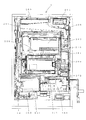
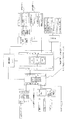
前記遊技機1の裏側には、図2に示すように、複数の制御基板や装置等が設けられている。制御基板の主なものとして、主制御基板200、サブ制御基板205、表示制御基板210、音声制御基板220、払出制御基板240、電源基板250、発射制御基板260等がある。符号265は外部端子、281は払出装置、283は球無し検出センサ、289は球貯留タンク、291は球誘導樋である。271はRAMクリアスイッチ、272は電源スイッチである。なお各制御基板には制御回路が設けられている。また、各制御基板は、単独でまたは複数まとめてケースに収納された状態で遊技機1の裏側に配置されている。主な制御基板を、図3のブロック図を用いて簡略に示す。
As shown in FIG. 2, a plurality of control boards, devices, and the like are provided on the back side of the
主制御基板200は、遊技情報に従って遊技の進行を制御する制御装置に相当する。前記主制御基板200には、CPU、RAM、ROMおよび複数のカウンタを備えたマイクロコンピュータを少なくとも備え、サブ制御基板205及び払出制御基板240と接続され、また中継回路を介して上側始動入賞口41、下側始動入賞口42及び大入賞口45等と接続されている。前記主制御基板200は電源基板250から電源供給を受けて作動する。
The
前記主制御基板200におけるCPUは、制御部、演算部、各種カウンタ、各種レジスタ,各種フラグ等を備え、演算制御を行う他、乱数値も生成し、また指令信号(制御信号あるいはコマンドとも称される)を接続されているサブ制御基板205や装置等へ出力(送信)可能に構成されている。また、前記主制御基板200のCPUは制御プログラムを実行して遊技情報に従って遊技に関わる主制御を行う。遊技情報は、当否判定に関する確率情報や、前記入賞装置への入賞情報や、払出情報、ラウンド状態、演出に関する情報等、遊技の進行に必要な情報である。
The CPU in the
前記主制御基板200から出力される指令信号(コマンド)には、入賞コマンド、始動入賞口入賞コマンド、大当たりオープニングコマンド、変動コマンド、変動停止コマンド、大当たりコマンド、大当たりラウンドコマンド、大当たりエンディングコマンド等がある。前記変動コマンドには、前記表示装置10で特別図柄を変動表示させて演出を行う変動パターンのコマンドや図柄に関するコマンドが含まれる。前記主制御基板200から出力される指令信号には、その他、普通図柄当たりに関するデータ、電源投入時、異常時、大当たりラウンド時等のデータを挙げることができる。なお、主制御基板200が前記表示装置10の制御に関して出力する指令信号に基づいて、サブ制御基板205が前記表示装置10に表示する内容を設定する。
Command signals (commands) output from the
前記RAMは、サブ制御基板205のRAMと共に保留記憶手段にも相当し、前記上側始動入賞口検出スイッチ及び下側始動入賞口検出スイッチで検出された遊技球の特別図柄保留球数、取得された乱数値の記憶領域、普通図柄変動開始スイッチで検出された遊技球の普通図柄保留球数の記憶領域、CPUで生成される各種乱数値用の記憶領域、遊技に必要な遊技データ等の各種データを一時的に記憶する記憶領域や、遊技情報を記憶する記憶領域やフラグ、CPUの作業領域を備える。
The RAM corresponds to the storage means together with the RAM of the
前記ROMは、前記CPUのための制御プログラムや制御データ、前記表示装置での変動表示に関する変動パターンや図柄データ、演出時間等のデータが書き込まれている他、大当たり、普通図柄当たりの判定値等が書き込まれている。 In the ROM, control programs and control data for the CPU, variation patterns and symbol data relating to variation display on the display device, data such as presentation time, etc. are written, judgment values per jackpot, ordinary symbol, etc. Has been written.
サブ制御基板205は、前記主制御基板200と接続されて主制御基板200から指令信号を受信可能に構成されると共に、前記表示制御基板210と接続されて表示装置10を制御可能に構成されている。前記サブ制御基板205にはCPU、ROM、RAM、複数のカウンタを備えたマイクロコンピュータと、前記主制御基板200とを結ぶ入出力回路と、前記表示制御基板210、ランプ中継基板、前記音声制御基板220、及び前記遊技操作スイッチ67とを結ぶ入出力回路を備えている。前記サブ制御基板205は、前記主制御基板200と共に遊技の制御を行う遊技制御手段に相当し、前記主制御基板200から出力された指令信号に従って遊技の制御を行う。本実施例ではサブ制御基板205はランプ制御基板を兼ねており、前記主制御基板200から出力された指令信号を受信し、受信した指令信号に基づいて、ランプ中継基板や表示制御基板210へ指令信号を出力している。前記主制御基板200からの指令信号には、前記表示装置10をサブ制御基板205が制御するための指令信号及び前記ランプ装置35に対するデータや信号、入賞コマンド、始動入賞口入賞コマンド、変動コマンド、大当たりコマンド等が含まれ、それらの信号の内容に合わせて遊技の制御を行っている。また、前記サブ制御基板205のROMは制御用のプログラムやデータ定数、前記表示装置10で実行される変動パターンによる演出等や背景演出情報が記憶され、また前記RAMは、主制御基板200のRAMと共に保留記憶手段にも相当し、各種データの記憶領域とCPUによる作業領域を有している。前記ランプ中継基板には装飾ランプ等のランプ装置35が接続され、前記サブ制御基板205からランプ中継基板に送信された指令信号によって、ランプ装置35の作動を制御する。前記サブ制御基板205は電源基板250から電源供給を受けて作動する。
The
表示制御基板210は、CPU、ROM、RAMを備えたマイクロコンピュータと、前記サブ制御基板205を結ぶ入力回路と前記表示装置10を結ぶ出力回路等で構成され、前記サブ制御基板205から送信された制御信号に基づいて、前記表示装置10における表示の制御を行う。前記表示制御基板210のROMには制御用のプログラムが記憶されている。前記表示制御基板210は、前記サブ制御基板205からの指令信号に基づき、表示制御御基板210のCPUがROMから所定の表示制御データを読み出し、RAMの記憶領域で制御用データを生成してVDP(図示せず)に出力する。VDPは、CPUからの指令に基づいてROMから必要なデータを読み出し、表示画像のマップデータを作成し、VRAMに格納する。VRAMに格納記憶された画像データは、出力回路に備えるD/A変換回路にてRGB信号に変換されて表示装置10に出力される。
The
音声制御基板220は、前記サブ制御基板205から出力される信号により音声信号を合成し、アンプに出力する。アンプは音声信号を増幅してスピーカ38に出力する。
The
払出制御基板240は、遊技球の払出を制御する払出制御手段に相当し、CPU、ROM、RAMを備えたマイクロコンピュータを有する。前記払出制御基板240は前記主制御基板200と電気的接続手段で接続され、前記主制御基板200から出力される指令信号を受信して払出装置281を制御する。前記払出制御基板240は電源基板250から供給される電源によって作動する。前記払出制御基板240のROMには制御用のプログラムが記憶されている。前記払出制御基板240のRAMは、種々の入賞口(入賞装置)への入賞検出に基づき前記払出装置281により払い出される賞品球(遊技球)の払出個数を、1入賞球の検出に対する払出個数毎に記憶可能となっている。
The
前記払出装置281は、入賞領域に遊技媒体が入賞することを起因にして遊技者に所定個数の遊技媒体を付与する遊技媒体付与手段に相当する。前記払出装置281は、払出モータの駆動によって回転する払出スクリューを備え、前記球誘導樋291から誘導されてきて払出装置281に至った遊技球を払出スクリューの羽根部分に乗せて払出スクリューが回転することにより徐々に下方へ移動させて遊技球の払い出し行うように構成されている。前記球誘導樋291と払出装置281の間における遊技球の流路に遊技球の存否を検出する前記球無しセンサ283が設けられている。前記払出装置281の球出口には、前記払出装置281から払い出された遊技球を検出する払出センサが設けられている。 The payout device 281 corresponds to a game medium giving means for giving a predetermined number of game media to the player due to the game media winning in the winning area. The payout device 281 includes a payout screw that rotates by driving of a payout motor, and the payout screw rotates by placing a game ball guided from the ball guide rod 291 and reaching the payout device 281 on the blade portion of the payout screw. Accordingly, the game ball is paid out by gradually moving downward. The no-ball sensor 283 for detecting the presence or absence of a game ball is provided in the flow path of the game ball between the ball guide bar 291 and the payout device 281. A payout sensor that detects a game ball paid out from the payout device 281 is provided at a ball exit of the payout device 281.
電源基板250は、遊技機1の外部より供給される主電源から遊技機1に適する所定電圧の遊技機用電源を生成して主制御基板(遊技制御装置)200やサブ制御基板205、払出制御基板240等に供給するものであり、電源装置に相当する。前記主電源は、遊技店側で所要の電圧、本実施例では直流(AC)24Vに変換されて供給される。
発射制御基板260は、前記発射装置64における発射モータの制御を行う。
The
The launch control board 260 controls the launch motor in the launch device 64.
前記主制御基板200に設けられる乱数用カウンタとして、大当たり乱数用カウンタ、大当たり図柄乱数用カウンタ、リーチ乱数用カウンタ、特別図柄データ乱数用カウンタ、変動パターン乱数用カウンタ、普通図柄乱数用カウンタ等がある。
The random number counter provided on the
大当たり乱数用カウンタは、当否判定手段による大当たりの判定(当否判定)に用いられ、‘0’〜‘629’の乱数からなる。前記大当たり乱数用カウンタの乱数(大当たり乱数)は、遊技機の電源投入時に
‘0’から始まって後述の普通図柄・特別図柄主要乱数更新処理ごとに1加算され、‘629’に至ると次には‘0’にされて再び前記加算を繰り返すようになっている。大当たり乱数値は前記上側始動入賞口41あるいは下側始動入賞口42への入賞に起因して取得され、その取得値が低確率(2/630(1/315))状態時には大当たり成立数値として設定されている‘3’,‘397’の何れかと一致すれば大当たりとなり、一方高確率(12/630(6/315))状態時(確変状態時)には、大当たり成立数値として設定されている‘3’,‘33’‘53’,‘59’,‘113’,‘173’,‘227’,‘281’,‘337’,‘397’,‘449’,‘503’の何れかと一致すれば大当たりとなる。
The jackpot random number counter is used for jackpot determination (whether or not) by the hit determination means, and consists of random numbers from “0” to “629”. The random number of the jackpot random number counter (the jackpot random number) is incremented by 1 every time a normal symbol / special symbol main random number update process to be described later starts at “0” when the gaming machine is turned on. Is set to “0” and the addition is repeated again. The jackpot random value is acquired due to winning at the upper start winning opening 41 or the lower starting winning opening 42, and is set as a jackpot value when the acquired value is in a low probability (2/630 (1/315)) state. If it matches any of '3' or '397', it is a big hit, while at the time of high probability (12/630 (6/315)) state (in the probability variation state), it is set as a big success value '3', '33' 53 ',' 59 ',' 113 ',' 173 ',' 227 ',' 281 ',' 337 ',' 397 ',' 449 ',' 503 ' It will be a big hit.
大当たり図柄乱数用カウンタは、大当たりの当否判定結果が大当たりの場合に前記表示装置10に確定停止する大当たり図柄組合せを決定するものであり、‘0’〜‘11’の乱数からなる。この大当たり図柄乱数は、電源投入時に‘0’から始まって後述の普通図柄・特別図柄主要乱数更新処理ごとに1加算され、‘11’に至ると次には‘0’に戻って再び前記加算を繰り返すようになっている。大当たり図柄乱数は前記上側始動入賞口41又は下側始動入賞口42への入賞に起因して取得される。前記大当たり図柄乱数には、当否判定結果が大当たりの場合に、前記表示装置10で停止表示される大当たり図柄組合せが割り当てられている。本実施例では、大当たり図柄乱数が‘0’の場合には大当たり図柄組合せが『0,0,0』となる0のぞろ目(全図柄同一)、‘1’の場合には大当たり図柄組合せが『1,1,1』となる1のぞろ目(全図柄同一)、‘2’の場合には『2,2,2』となる2のぞろ目、‘3’の場合には『3,3,3』となる3のぞろ目、‘4’の場合には『4,4,4』となる4のぞろ目、以下同様にして大当たり図柄乱数が‘11’の場合の大当たり図柄組合せ『11,11,11』まで、大当たり図柄乱数に大当たり図柄組合せが割り当てられている。
The jackpot symbol random number counter determines a jackpot symbol combination to be confirmed and stopped in the
また、本実施例では、前記大当たり図柄乱数は、大当たりの場合に確変の決定にも用いられる。
確変(確変大当たり)の場合には、特別遊技(大当たり遊技)の終了後、次に大当たりの当否判定によって大当たりと判定されるまで、大当たりの確率が前記高確率状態(確変状態)とされる。なお確変ではない通常大当たり場合には、特別遊技(大当たり遊技)の終了後、次に大当たりの当否判定によって大当たりと判定されるまで、大当たりの確率が前記低確率状態(通常状態)とされる。本実施例では、当否判定結果が大当たりであって前記大当たり図柄乱数が‘1’、‘3’、‘5’、‘7’、‘9’、‘11’の何れかの奇数の場合に、すなわち前記表示装置10に停止表示される大当たり図柄の組合せが『1,1,1』、『3,3,3』、『5,5,5』、『7,7,7』、『9,9,9』、『11,11,11』の何れかの奇数の組合せ(奇数のぞろ目)の場合に高確率状態(確変状態)となる。
一方、当否判定結果が大当たりであって前記大当たり図柄乱数が‘0’、‘2’、‘4’、‘6’、‘8’、‘10’の何れかの偶数の場合に、すなわち前記表示装置10に停止表示される大当たり図柄の組合せが『0,0,0』、『2,2,2』、『4,4,4』、『6,6,6』、『8,8,8』、『10,10,10』の何れかの偶数の組合せ(偶数のぞろ目)の場合に低確率状態(通常状態)となる。
In the present embodiment, the jackpot symbol random number is also used to determine the probability variation in the case of jackpot.
In the case of a probability change (probability jackpot), the probability of jackpot is set to the high probability state (probability change state) after the special game (jackpot game) ends until it is determined next as a jackpot by determining whether or not the jackpot is successful. In the case of a normal jackpot that is not a probable change, the probability of a jackpot is set to the low probability state (normal state) after the special game (a jackpot game) is finished until the jackpot is determined to be a jackpot by the next jackpot determination. In this embodiment, when the determination result is a jackpot and the jackpot symbol random number is any one of '1', '3', '5', '7', '9', '11', That is, combinations of jackpot symbols that are stopped and displayed on the
On the other hand, when the determination result is a jackpot and the jackpot symbol random number is any one of “0”, “2”, “4”, “6”, “8”, “10”, that is, the display The combinations of jackpot symbols that are stopped and displayed on the
また、確変(高確率)状態になると、前記当否判定における大当たりの確率が前記高確率(確変)状態になると共に前記下側始動入賞口42の開放(拡開)時間が、低確率(通常)状態の1秒から2秒に長くなり、かつ前記下側始動入賞口42の開放(拡開)回数が低確率(通常)状態の1回から3回に増え、さらに、普通図柄当たりの確率が低確率(通常)状態の1/300から1/5に増加する。
前記低確率状態(通常状態)は通常遊技に相当し、一方、前記高確率状態(確変状態)は、通常遊技よりも遊技者に有利な特典を付与した特典遊技に相当する。なお、前記特典は、前記下側始動入賞口42の開放(拡開)時間の短縮及び開放回数の増大、普通図柄当たりの確率増大、あるいは大当たりの確率増大の何れか一のみでもよい。
Further, when the probability variation (high probability) state is reached, the jackpot probability in the determination of success or failure becomes the high probability (probability variation) state, and the opening (expansion) time of the lower start winning opening 42 is low probability (normal). The number of times of opening (expanding) of the lower start winning opening 42 is increased from 1 to 3 times in the low probability (normal) state, and the probability per normal symbol is increased. It increases from 1/300 to 1/5 of the low probability (normal) state.
The low probability state (normal state) corresponds to a normal game, while the high probability state (probability change state) corresponds to a privilege game that gives a privilege more advantageous to the player than the normal game. The benefit may be any one of shortening the opening (expansion) time of the lower start winning opening 42 and increasing the number of times of opening, increasing the probability per ordinary symbol, or increasing the probability per jackpot.
リーチ乱数用カウンタは、前記大当たり乱数値による大当たりの当否判定結果が外れとなる場合において、リーチ状態を経るか否かを決めるリーチ有無決定用のものであり、‘0’〜‘126’の乱数からなる。本実施例におけるリーチ状態は、前記表示装置10で変動停止表示される左特別図柄、中特別図柄及び右特別図柄のうち、最後に停止表示される特別図柄(例えば中特別図柄)を除いて他の特別図柄(例えば左特別図柄と右特別図柄)が同一となる状態(最終停止図柄を除いて大当たりの特別図柄組合せと等しくなる状態であり、最終的に大当たりの特別図柄組合せとなる場合と外れの特別図柄組合せとなる場合が含まれる状態)をいう。このリーチ乱数用カウンタの乱数(リーチ乱数)は、遊技機1の電源投入時に、‘0’から始まり、後述の普通図柄・特別図柄主要乱数更新処理ごとに1ずつ加算され、数値が‘126’に至ると、次に‘0’にされて再び前記加算を繰り返すようになっている。リーチ乱数は、前記上側始動入賞口41あるいは下側始動入賞口42への入賞に起因して取得され、当否判定結果が外れの場合に、その数値が予め決定されているリーチ成立数値と対比されてリーチ有無が判断される。本実施例ではリーチ成立数値は、‘5’,‘17’,‘28’,‘40’,‘51’,‘63’,‘74’,‘86’,‘97’,‘109’,‘120’に設定されている。
The reach random number counter is used for determining whether or not a reach state is reached when the jackpot determination result based on the jackpot random number value is out of reach, and is a random number of “0” to “126”. Consists of. The reach state in the present embodiment is other than the special symbol (for example, the middle special symbol) that is stopped and displayed last among the left special symbol, the middle special symbol, and the right special symbol that are displayed on the
特別図柄データ乱数用カウンタは、前記大当たり乱数値による大当たり判定結果が外れとなる場合において、前記表示装置10に停止表示する外れの特別図柄組合せの決定に用いられるものであり、前記表示装置10に停止表示する左特別図柄を決定する特別図柄データ1の乱数用カウンタと、中特別図柄を決定する特別図柄データ2の乱数用カウンタと、右特別図柄を決定する特別図柄データ3の乱数用カウンタとより構成され、各特別図柄データ乱数用カウンタは、‘0’〜‘11’の乱数からなる。
The special symbol data random number counter is used for determining a special symbol combination that is to be stopped and displayed on the
前記特別図柄データ1の乱数は、電源投入時に、‘0’から始まって後述の普通図柄・特別図柄主要乱数更新処理ごとに
‘1’ずつ加算され、‘11’に至ると、次に‘0’に書き換えられて再び前記加算が繰り返される。また、前記特別図柄データ2の乱数は、電源投入時に‘0’から始まって、前記特別図柄データ1の乱数が‘0’に書き換えられる際に‘1’ずつ加算され、‘11’に至ると、次に‘0’に書き換えられて再び前記加算が繰り返される。さらに、前記特別図柄データ3の乱数は、電源投入時に‘0’から始まって、前記特別図柄データ2の乱数が‘0’に書き換えられる際に‘1’ずつ加算され、‘11’に至ると、次に‘0’に書き換えられて再び前記加算が繰り返される。これによって、特別図柄データ1〜3の乱数範囲が同一であっても、当該特別図柄データ1〜3の乱数が同期(同一の組合せで加算)するのを避けることができる。
The random number of the
前記特別図柄データ1〜3の各乱数は‘0’の場合には『0』、‘1’の場合には『1』、‘2’の場合には『2』というように、当否判定結果の外れ時に前記表示装置10に停止表示される左特別図柄、中特別図柄、右特別図柄からなる識別情報が割り当てられている。前記特別図柄データ1〜3の乱数は、前記上側始動入賞口41又は下側始動入賞口42への入賞に起因して取得され、取得した特別図柄データ1〜3の乱数の組合せによって、外れ時に前記表示装置10に表示される左特別図柄、中特別図柄、右特別図柄からなる識別情報が定まる。
Each random number of the
変動パターン乱数用カウンタは、前記表示装置10における特別図柄(判定図柄)の変動パターンを変動パターンテーブルから選択する際に用いられるものであり、‘0’〜‘198’の変動パターン乱数を備える。この変動パターン乱数値は、遊技機1の電源投入時に、‘0’から始まり、後述の普通図柄・特別図柄主要乱数更新処理ごとに1ずつ加算され、数値が‘198’に至ると、次に‘0’にされて再び前記加算を繰り返すようになっている。前記変動パターン乱数値は、前記上側始動入賞口41あるいは下側側始動入賞口42への入賞に起因して取得される。
The variation pattern random number counter is used when a variation pattern of a special symbol (determination symbol) in the
前記変動パターンテーブルは複数設けられている。本実施例では、通常当たり変動パターンテーブル、通常リーチハズレ変動パターンテーブル、通常ハズレ変動パターンテーブル、確変当たり変動パターンテーブル、確変リーチハズレ変動パターンテーブル、確変ハズレ変動パターンテーブルからなる6種類のテーブルが設けられている。各変動パターンテーブルは、前記表示装置10に表示する特別図柄の変動パターンの複数で構成されており、前記主制御基板200のROMに記憶されている。変動パターンの選択は、本実施例では、遊技状態が確変状態あるいは通常状態の何れか、及び当否判定結果が当たりか外れかに応じて選択された変動パターンテーブルから、変動パターン乱数値に基づいて1つの変動パターンが選択される。通常当たり変動パターンテーブルからは通常当たり変動パターン、通常リーチハズレ変動パターンテーブルからは通常リーチハズレ変動パターン、通常ハズレ変動パターンテーブルからは通常ハズレ変動パターン、確変当たり変動パターンテーブルからは確変当たり変動パターン、確変リーチハズレ変動パターンテーブルからは確変リーチハズレ変動パターン、確変ハズレ変動パターンテーブルからは確変ハズレ変動パターンがそれぞれ選択される。各変動パターンには変動パターン乱数値が割り当てられており、取得した変動パターン乱数値と対応する変動パターンが選択される。各変動パターンには変動時間が設定されており、設定された変動時間に合わせて前記表示装置10に表示する特別図柄の変動・停止の表示態様(特別図柄の変動時間を含む)及び特別図柄の変動中あるいは停止後に表示する背景やキャラクター、文字等の演出態様等が定められるように構成されている。
A plurality of variation pattern tables are provided. In this embodiment, there are provided six types of tables including a normal hit variation pattern table, a normal reach loss variation pattern table, a normal loss variation pattern table, a probability variation variation pattern table, a probability variation reach loss variation pattern table, and a probability variation loss variation pattern table. Yes. Each variation pattern table is composed of a plurality of variation patterns of special symbols displayed on the
取得された大当たり乱数値、大当たり図柄乱数値、リーチ乱数値、変動パターン乱数値については、それぞれ最大設定個数、前記主制御基板200のRAMにおける該当領域に前記保留球数と対応させて格納され、順次使用される。
The acquired jackpot random number value, jackpot symbol random number value, reach random number value, and fluctuation pattern random number value are stored in correspondence with the number of reserved balls in the corresponding area in the RAM of the
普通図柄乱数用カウンタは、普通図柄当たりを判定するもので、‘0’〜‘299’の普通図柄乱数を有し、遊技機1の電源投入時に、‘0’から始まって後述の普通図柄・特別図柄主要乱数更新処理ごとに
‘1’ずつ加算され、‘299’に至ると、次に‘0’に書き換えられて再び前記加算が繰り返される。この普通図柄乱数は、前記普通図柄変動開始用ゲート55を通過した遊技球を前記普通図柄変動開始スイッチで検出するごとに取得され、最大4個まで前記主制御基板200のRAMの普通図柄乱数値記憶領域に格納される。前記普通図柄変動開始用ゲート55を遊技球が通過することに起因して取得された普通図柄乱数の値が、低確率状態時には普通図柄当たり成立数値として設定されている‘5’(1/300の確率)と一致すれば普通図柄当たりとなり、一方、確変(高確率)状態時には普通図柄当たり成立数値として設定されている‘0’〜‘59’(1/5)の確率)と一致すれば普通図柄当たりとなる。普通図柄当たりの場合には『○』を普通図柄表示装置50に表示し、前記下側始動入賞口42を前記確変状態中か否かに対応した開放回数及び開放時間開放し、一方、取得した普通図柄乱数値が普通図柄当たり成立数値と一致しない場合には、普通図柄外れとなって『×』を普通図柄表示装置50に表示し、前記下側始動入賞口42を入賞の困難な状態のままとする。
The normal symbol random number counter is used to determine a normal symbol per unit, and has a normal symbol random number of “0” to “299”. When the
前記サブ制御基板205に設けられる乱数用カウンタとして、ステップアップ予告乱数用カウンタと、ステップ数乱数用カウンタとがある。
ステップアップ予告乱数用カウンタは、ステップアップ予告(本発明の段階的表示予告に相当する)を行うか否かを予告決定手段で決定する際に用いられるものであり、‘0’〜‘99’のステップアップ予告乱数を備える。このステップアップ予告乱数は、遊技機1の電源投入時に、‘0’から始まり、後述のサブ制御メイン処理における乱数シード更新処理ごとに1ずつ加算され、‘99’に至ると、次に‘0’に戻って再び前記加算を繰り返すようになっている。本実施例では、予告決定手段において、取得されたステップ予告乱数値が‘0’〜‘49’の場合にステップアップ予告を行う(段階的表示予告を行う)に決定され、一方、取得されたステップ予告乱数値が‘50’〜‘99’の場合にステップアップ予告を行わない(段階的表示予告を行わない)に決定される。ステップアップ予告(段階的表示予告)は、前記表示装置10で当否判定手段の判定結果を表示する前(本実施例では、前記特別図柄が停止表示する前)に、前記当否判定手段の判定結果を、前記表示装置10で段階的にキャラクターを表示させることで示唆する演出態様である。
As the random number counter provided on the
The step-up notice random number counter is used when the notice determining means determines whether or not to perform the step-up notice (corresponding to the step-by-step display notice of the present invention). '0' to '99' Step-up notice random number is provided. This step-up notice random number starts from “0” when the
ステップ数乱数用カウンタは、ステップアップ予告を行う場合に、第1制御手段が、ステップアップ予告の段階数(段階的表示予告の段階数)を当否判定手段の判定結果に基づいて選択する際に用いられるものであり、‘0’〜‘89’のステップ数乱数を備える。このステップ数乱数は、遊技機1の電源投入時に、‘0’から始まり、後述のサブ制御メイン処理における乱数シード更新処理ごとに1ずつ加算され、‘89’に至ると、次に‘0’に戻って再び前記加算を繰り返すようになっている。
The step number random number counter is used when the first control means selects the number of stages of the step-up notice (the number of stages of the step-by-step notice) based on the determination result of the success / failure determination means when performing the step-up notice. It is used, and comprises step number random numbers from “0” to “89”. This step number random number starts from “0” when the
本実施例では、当否判定手段の判定結果が当たりの場合には、取得されたステップ数乱数値が‘0’〜‘9’については、ステップ1(段階1)→ステップ2(段階2)の順に表示するステップ数(段階数)2に決定され、取得されたステップ数乱数値が‘10’〜‘24’については、ステップ1(段階1)→ステップ2(段階2)→ステップ3(段階3)の順に表示するステップ数(段階数)3に決定され、取得されたステップ数乱数値が‘25’〜‘84’については、ステップ1(段階1)→ステップ2(段階2)→ステップ3(段階3)→ステップ4(段階4)の順に表示するステップ数(段階数)4に決定され、取得されたステップ数乱数値が‘85’〜‘89’については、ステップ2(段階2)→ステップ4(段階4)の順に表示するステップ数(段階数)2に決定される。 In the present embodiment, when the determination result of the determination unit is correct, the obtained step number random value is “0” to “9” from step 1 (stage 1) to step 2 (stage 2). The number of steps (number of steps) to be displayed in order is determined to be 2 and the obtained step number random number values “10” to “24” are step 1 (step 1) → step 2 (step 2) → step 3 (step 3) The number of steps (number of stages) to be displayed is determined to be 3 and the obtained step number random number values “25” to “84” are step 1 (stage 1) → step 2 (stage 2) → step. 3 (stage 3) → step 4 (stage 4) is determined to be the number of steps (stage number) 4 to be displayed in order, and the obtained step number random value is “85” to “89”, step 2 (stage 2) ) → Step 4 (Stage 4) It is determined in two steps the number to be displayed (number of steps).
一方、当否判定手段の判定結果が外れの場合には、取得されたステップ数乱数値が‘0’〜‘59’については、ステップ1(段階1)→ステップ2(段階2)の順に表示するステップ数(段階数)2に決定され、取得されたステップ数乱数値が‘60’〜‘79’については、ステップ1(段階1)→ステップ2(段階2)→ステップ3(段階3)の順に表示するステップ数(段階数)3に決定され、取得されたステップ数乱数値が‘80’〜‘87’については、ステップ1(段階1)→ステップ2(段階2)→ステップ3(段階3)→ステップ4(段階4)の順に表示するステップ数(段階数)4に決定され、取得されたステップ数乱数値が‘87’〜‘89’については、ステップ2(段階2)→ステップ4(段階4)の順に表示するステップ数(段階数)2に決定される。 On the other hand, when the determination result of the success / failure determination unit is out of order, the acquired step number random number values “0” to “59” are displayed in the order of step 1 (stage 1) → step 2 (stage 2). Step number (stage number) is determined to be 2 and the obtained step number random value is “60” to “79”, step 1 (stage 1) → step 2 (stage 2) → step 3 (stage 3). The number of steps (number of stages) to be displayed in order is determined to be 3, and the obtained step number random value is “80” to “87”, step 1 (stage 1) → step 2 (stage 2) → step 3 (stage 3) → step 4 (stage 4) is determined to be the number of steps (stage number) 4 to be displayed in order, and when the obtained step number random number values are “87” to “89”, step 2 (stage 2) → step Display in order of 4 (stage 4) Step number (the number of steps) are determined in two.
このように、当否判定結果が当たりの場合には、ステップアップ予告のステップ数(段階的表示予告の段階数)が多い予告が選択されやすく、一方、当否判定結果が外れの場合には、ステップアップ予告のステップ数(段階的表示予告の段階数)が少ない予告が選択されやすくなっている。そのため、ステップ数(段階数)の多いステップアップ予告(段階的表示予告)が表示されることによって、当否判定結果が当たりの可能性が高いことを示唆する、すなわち、その後に前記表示装置10で当否判定結果の当たりが報知(表示)される可能性が高いことを示唆し、逆にステップ数(段階数)の少ないステップアップ予告(段階的表示予告)が表示されることによって、当否判定結果が外れの可能性が高いことを示唆する。すなわち、その後に前記表示装置10で当否判定結果の外れが報知(表示)される可能性が高いことを示唆する。また、ステップ2(段階2)→ステップ4(段階4)については、当たりの場合と外れの場合の何れについても他のステップ数(段階数)よりも選択率が低くされ、かつ当たりの場合の方が選択率が高く設定されているため、ステップ2(段階2)→ステップ4(段階4)が表示されることによって、当たりに対する期待感を高めることができる。
As described above, when the result is correct, it is easy to select a notice with a large number of steps for the step-up notice (the number of stages of the step-by-step display notice). It is easy to select a notice with a small number of steps of up notice (number of stages of staged display notice). Therefore, by displaying a step-up notice (step-by-step display notice) with a large number of steps (stage number), it is suggested that the determination result is highly likely to win, that is, the
前記遊技機1の遊技を簡略に説明する。前記遊技機1では、遊技領域6へ向けて発射装置64により発射された遊技球が、前記種々の入賞口に入賞すると入賞口に応じた所定数の遊技球が賞球として前記払出装置281から上側球受け皿36に払い出される。また、前記普通図柄変動開始用ゲート55を遊技球が通過すると、普通図柄乱数が取得され、その取得乱数値に基づいて普通図柄当たりの判定が行われると共に、前記普通図柄表示装置50で普通図柄が変動を開始し、所定時間変動後に停止する。その際、普通図柄当たりの判定結果が当たりの場合には、当たり普通図柄、この例では『○』で停止し、前記下側始動入賞口42の2つの可動片42a,42bが背面の始動入賞口用ソレノイドによって略垂直で入賞困難な閉鎖状態(通常状態)から略V字形(逆ハの字形)の入賞可能な開状態に変化する。なお、前記確変状態の場合に普通図柄当たりになると、前記下側始動入賞口42について2秒の開放が3回行われ、一方、低確率状態の場合に普通図柄当たりになると、1秒の開放が1回行われる。前記下側始動入賞口42に遊技球が入賞すると、所定数の遊技球が賞球として払い出される。
The game of the
また、前記上側始動入賞口41あるいは下側始動入賞口42に遊技球が入賞すると、特別図柄保留球数が4未満であれば、特別図柄保留球数を1加算して、大当たり乱数値、大当たり図柄乱数値、リーチ乱数値、変動パターン乱数値等の乱数値を取得し、前記主制御基板200のRAMに、最大4となるまで入賞順に記憶される。そして、前記主制御基板200のRAMに記憶されている特別図柄保留球数が1以上であれば先に取得された大当たり乱数値に基づいて大当たりの当否判定が行われると共に、当否判定結果及び変動パターン乱数値に基づいて変動パターンテーブルから1つの変動パターンが選択される。そして選択された変動パターンに基づいて前記表示装置10で特別図柄の変動表示が開始される。前記特別図柄保留球数は、本実施例では前記特別図柄の変動開始により前記主制御基板200のRAMから1減算され、変動開始と対応する乱数値が前記主制御基板200のRAMから削除(消去)される。なお、主制御基板200のRAMに記憶されている特別図柄保留球数が0の場合には、その後に前記上側始動入賞口41あるいは下側始動入賞口42に遊技球が入賞して、前記主制御基板200のRAMに記憶されている特別図柄保留球数が1以上となるまで、前記当否判定及び特別図柄の変動表示が行われない。
Further, when a game ball is won in the upper start winning opening 41 or the lower start winning opening 42, if the number of special symbol reserved balls is less than 4, the special symbol reserved ball number is incremented by 1 to obtain a jackpot random number value, jackpot Random values such as symbol random values, reach random values, and fluctuation pattern random values are acquired and stored in the RAM of the
また、前記ステップアップ予告乱数値が取得されてステップアップ予告(段階的表示予告)を行うと決定された場合には、前記特別図柄の変動表示が前記表示装置10で行われる際に、大当たりの当否判定結果に基づき前記ステップ数乱数値を用いて決定された段階数(ステップ数)のステップアップ予告(段階的表示予告)が行われる。ステップアップ予告は、前記表示装置10に段階的にキャラクターを表示させる予告演出である。
Further, when it is determined that the step-up notice random number value is acquired and the step-up notice (step-by-step display notice) is performed, when the display of the special symbol is performed on the
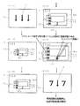
ステップアップ予告(段階的表示予告)の例を次に示す。図4に示すステップアップ予告(段階的表示予告)は、当否判定結果の表示(報知)が大当たりの可能性の高い段階数(ステップ数)4の場合であり、すなわちステップ1(段階1)→ステップ2(段階2)→ステップ3(段階3)→ステップ4(段階4)の順に段階的表示予告が行われる。 An example of step-up notice (step-by-step notice) is shown below. The step-up notice (step-by-step notice) shown in FIG. 4 is a case where the display (notification) of the determination result is a stage number (step number) 4 that is likely to be a big hit, that is, step 1 (stage 1) → A stepwise display notice is performed in the order of step 2 (stage 2) → step 3 (stage 3) → step 4 (stage 4).
まず、図4の(4−1)に示すように、前記表示装置10で前記特別図柄Tの変動表示中に、図4の(4−2)に示すように、ステップアップ予告(段階的表示予告)のステップ1(段階1)の表示が行われる。ステップ1(段階1)の表示では段階1のキャラクターとして外枠qaと内枠qbの二重フレームからなるウインドウQ1が表示される。前記ウインドウQ1(キャラクター)は、段階を示す数を認識できる少なくとも2つの表示態様、図示の例では第1表示態様U1と第2表示態様U2が付与されて表示される。前記段階を示す数は、数字のように直接的に認識できるものの以外に、インジケータで数字を表すものや、図形の数で表すもの、あるいは図形を複数分割したときの各分割した数や数以外でもその形状で数を認識できるものの変化など、その段階を示す数を間接的に認識できるものや示唆できる表示態様であってもよい。図示の例では、前記ウインドウQ1の外枠qaと内枠qbの間における下部に第1表示態様U1、左側部に第2表示態様U2を有する。前記外枠qaと内枠qb間は模様等の装飾態様で構成された装飾態様部分に相当し、前記ウインドウ(キャラクター)Q1の少なくとも一部が前記装飾態様で表示されている。
First, as shown in (4-1) of FIG. 4, during the change display of the special symbol T on the
前記第1の表示態様U1は数字で構成されている。図4の(4−2)に示す1段階では、前記第1表示態様U1は数字の「1」が表示され、現在の予告表示段階が1段階目であることが示される。
前記第2表示態様U2は、円形の装飾部u1〜u4が段階数(図示の例では段階数4)と同等の数分(図示の例では4)だけ縦に配置されたもので構成され、現在の段階の数分だけ色を変更(変化)させて表示される。図4の(4−2)に示す1段階では、前記第2表示態様U2は、1段階分の1個だけ装飾部u1が所定色に変更されることにより、現在の予告表示段階が1段階目であることを示す。
なお、図4の(4−2)に示す1段階目では、前記ウインドウQ1からなるキャラクターは、前記表示装置10の中央位置に小さく表示される。また、前記特別図柄Tは、前記表示装置10の左上で変動表示される。
The first display mode U1 is composed of numerals. In the first stage shown in (4-2) of FIG. 4, the number “1” is displayed in the first display mode U1, indicating that the current notice display stage is the first stage.
The second display mode U2 is configured by vertically arranging the circular decorative portions u1 to u4 by a number (4 in the illustrated example) equivalent to the number of stages (4 in the illustrated example), It is displayed with the color changed (changed) by the number of the current stage. In one stage shown in (4-2) of FIG. 4, the second display mode U2 changes the decoration part u1 to a predetermined color for one stage, so that the current notice display stage is one stage. Indicates eyes.
In the first stage shown in (4-2) of FIG. 4, the character consisting of the window Q1 is displayed small at the center position of the
前記1段階目の予告が所定時間表示された後、2段階目の予告が表示される。2段階目では、図4の(4−3)に示すように、段階2のキャラクターとして、前記ウインドウQ1が所定量拡大された状態のウインドウQ2が表示されると共に、前記第1表示態様U1は数字の「2」が表示され、かつ前記第2表示態様U2は2段階分の2個の装飾部u1、u2が所定色に変更され、前記第1表示態様U1と第2表示態様U2のそれぞれは、現在の予告表示段階が2段階目であることを示す。
After the first stage notice is displayed for a predetermined time, the second stage notice is displayed. In the second stage, as shown in (4-3) of FIG. 4, a window Q2 in which the window Q1 is enlarged by a predetermined amount is displayed as the character of
前記2段階目の予告表示が所定時間表示された後、3段階目の予告が表示される。3段階目では、図4の(4−4)に示すように、段階3のキャラクターとして、前記ウインドウQ2が所定量拡大された状態のウインドウQ3が表示されると共に、前記第1表示態様U1は数字の「3」が表示され、かつ前記第2表示態様U2は3段階分の3個の装飾部u1、u2、u3が所定色に変更され、前記第1表示態様U1と第2表示態様U2のそれぞれは、現在の予告表示段階が3段階目であることを示す。
After the second stage notice display is displayed for a predetermined time, the third stage notice is displayed. In the third stage, as shown in (4-4) of FIG. 4, a window Q3 in which the window Q2 is enlarged by a predetermined amount is displayed as the character of
前記3段階目の予告表示が所定時間表示された後、4段階目の予告が表示される。4段階目では、図4の(4−5)に示すように、段階4のキャラクターとして、前記ウインドウQ3が所定量拡大された状態のウインドウQ4が表示されると共に、前記第1表示態様U1は数字の「4」が表示され、かつ前記第2表示態様U2は4段階分の4個の装飾部u1、u2、u3、u4が所定色に変更され、前記第1表示態様U1と第2表示態様U2のそれぞれは、現在の予告表示段階が4段階目であることを示す。
After the third stage notice display is displayed for a predetermined time, the fourth stage notice is displayed. In the fourth stage, as shown in (4-5) of FIG. 4, a window Q4 in which the window Q3 is enlarged by a predetermined amount is displayed as the character in
このように予告表示段階が4段階まで表示されたことにより、その後に行われる当否判定結果の表示(報知)が大当たりである可能性の高いことが示唆される。また、前記第1表示態様U1と前記第2表示態様U2の2種類の表示態様によって予告表示の段階を示すため、特別図柄の変動表示中に行われる演出効果(エフェクト)等によって一方の表示態様が見え難くいことがあっても、他方の表示態様によって段階を認識させることが可能である。なお、各装飾部u1〜u4の段階の前後の色や形については、キャラクターの装飾に合わせた形状であるとウインドウの装飾自体に違和感を感じることを低減することが可能である。また、段階数の前後の色や形が明らかに異なるようにするとより明確に段階数を認識することが可能である。 Thus, it is suggested that the display (notification | reporting) of the success / failure determination result performed after that is displayed up to four stages of the notice display stage is likely to be a big hit. In addition, since the stage of the notice display is shown by the two types of display modes, the first display mode U1 and the second display mode U2, one display mode is used depending on the production effect (effect) etc. performed during the variable symbol display. Even if it is difficult to see, it is possible to recognize the stage by the other display mode. In addition, about the color and the shape before and after the stage of each decoration part u1-u4, it is possible to reduce feeling of uncomfortable feeling in the window decoration itself if it is a shape matched with the decoration of the character. In addition, if the colors and shapes before and after the number of stages are clearly different, the number of stages can be recognized more clearly.
前記第4段階目の予告表示が所定時間行われた後、図4の(4−6)に示すように、前記表示装置10の中央で前記特別図柄Tが変動表示され、変動パターンに設定されている変動時間の経過(変動時間の終了)により、前記表示装置10で特別図柄が当否判定結果に応じた図柄組合せで停止表示される。
遊技の当否判定結果が外れの場合には前記表示装置10に左特別図柄、中特別図柄、右特別図柄が外れ図柄組合せ(ぞろ目以外の状態)で停止し、特別遊技(大当たり遊技)に移行することがない。そして、前記主制御基板200のRAMに記憶されている特別図柄保留球数が1以上であれば、再び前記と同様に大当たり乱数値等が取得され、取得された大当たり乱数値に基づいて大当たりの当否判定が行われると共に、当否判定結果及び変動パターン乱数値に基づいて変動パターンテーブルから1つの変動パターンが選択され、選択された変動パターンに基づいて前記表示装置10で特別図柄の変動表示を含む演出が行われる。
After the fourth stage notice display is performed for a predetermined time, the special symbol T is variably displayed at the center of the
If the game success / failure determination result is out of place, the
一方、当否判定結果が大当たりの場合には、前記表示装置10に左特別図柄、中特別図柄、右特別図柄が大当たり図柄組合せ(本実施例ではぞろ目)で停止し、特別遊技(大当たり遊技)状態になる。
On the other hand, if the determination result is a jackpot, the left special symbol, the middle special symbol, and the right special symbol are stopped on the
大当たり遊技(特別遊技)状態になると、前記大入賞口45の開閉板46が開いて遊技領域6の表面を落下してくる遊技球を受け止め易くして、大入賞口45へ入賞可能にし、該大入賞口45への入賞があると、所定数の遊技球が賞球として払い出される。前記開閉板46は、所定時間(例えば15秒)経過後、或いは入賞球数が所定個数(例えば10個)となった時点で閉じるようにされ、15ラウンド、前記開閉板46の開閉を繰り返す。
In the big win game (special game) state, the open / close plate 46 of the big prize opening 45 is opened to make it easy to receive the game balls falling on the surface of the
また、本実施例では、前記表示装置10に『0,0,0』、『2,2,2』、『4,4,4』等の偶数のぞろ目からなる通常大当たり図柄組合せで特別図柄が停止表示されると通常大当たりとなり、特別遊技(大当たり遊技)の終了後、次に大当たりの当否判定が行われるまで、大当たりの確率が低確率(本実施例では(2/630(1/315))とされる。一方、前記表示装置10に『1,1,1』、『3,3,3』、『5,5,5』等の奇数のぞろ目からなる確変大当たり図柄組合せで特別図柄が停止表示されると確変大当たりとなり、特別遊技(大当たり遊技)の終了後、次に大当たりの当否判定が行われるまで、大当たりの確率が高確率(本実施例では(12/630(6/315))に設定され、さらに、前記下側始動入賞口42の開放(拡開)時間が、低確率(通常)状態の1秒から2秒に長くなり、かつ前記下側始動入賞口42の開放(拡開)回数が低確率(通常)状態の1回から3回に増え、さらに、普通図柄当たりの確率が低確率(通常)状態の1/300から1/5に増加する。
In this embodiment, the
以下に遊技機1における制御処理を説明する。前記主制御基板200の制御回路に設けられる主なフラグとして、本実施例では大当たりフラグ、大当たり終了フラグ、確変フラグ等が挙げられる。これらのフラグは、初期設定時には全てOFF(=0)にされる。
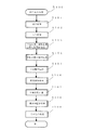
まず、前記主制御基板200による制御処理について説明する。前記主制御基板200の制御により、図5のフローチャートに示すメイン処理Mが行われる。
メイン処理Mでは、CPU等の初期設定処理(S10)、割り込み禁止処理(S20)、普通図柄・特別図柄主要乱数更新処理(S30)、割り込み許可処理(S40)が行われ、最終処理においてループ処理が行われている間に4ms毎に割り込み処理(S100)が実行される。
The control process in the
First, the control process by the
In the main process M, an initial setting process (S10) such as a CPU, an interrupt prohibition process (S20), a normal symbol / special symbol main random number update process (S30), an interrupt permission process (S40) are performed, and a loop process is performed in the final process. Is being performed, interrupt processing (S100) is executed every 4 ms.
CPU等の初期設定処理(S10)では、スタックの設定、割り込み時間の設定、CPUの設定、SIO、PIO、CTCの設定等が行われる。メイン処理Mは繰り返し行われるが、CPU等の初期設定処理(S10)については、電源投入時のみに必要な初期制御手順であり、最初の1巡目のみに実行され、その後は実行されないが、周知であるので詳細は省略する。 In the initial setting process (S10) of the CPU and the like, stack setting, interrupt time setting, CPU setting, SIO, PIO, CTC setting and the like are performed. Although the main process M is repeatedly performed, the initial setting process (S10) of the CPU or the like is an initial control procedure necessary only when the power is turned on, and is executed only in the first round, and is not executed thereafter. Details are omitted because they are well known.
割り込み禁止処理(S20)では、4msecごとに割り込み処理(S100)が入ってきても、割り込み許可となるまで、割り込みを禁止する。普通図柄・特別図柄主要乱数更新処理(S30)では、種々の乱数が普通図柄・特別図柄主要乱数更新処理(S30)ごとに加算され、前記のように各乱数の更新範囲上限値に至ると次に最低値に戻って再び加算が行われる。更新された乱数は前記主制御基板200のRAMに記憶される。割り込み許可処理(S40)では、4msecごとに入ってくる割り込み処理(S100)に対して許可をする。
In the interrupt prohibition process (S20), even if the interrupt process (S100) is entered every 4 msec, the interrupt is prohibited until the interrupt is permitted. In the normal symbol / special symbol main random number update process (S30), various random numbers are added for each of the normal symbol / special symbol main random number update process (S30). The value is returned to the minimum value and the addition is performed again. The updated random number is stored in the RAM of the
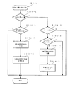
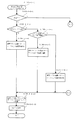
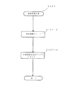
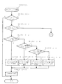
割り込み処理(S100)では、図6に示すように、出力処理(S101)、入力処理(S102)、普通図柄・特別図柄主要乱数更新処理(S103)、始動入賞口検出処理(S104)、普通動作処理(S105)、特別動作処理(S106)、保留球数処理(S107)、電源断監視処理(S108)、その他の処理(S109)が順に行われる。 In the interrupt process (S100), as shown in FIG. 6, the output process (S101), the input process (S102), the normal symbol / special symbol main random number update process (S103), the start winning opening detection process (S104), the normal operation Processing (S105), special operation processing (S106), reserved ball number processing (S107), power-off monitoring processing (S108), and other processing (S109) are performed in this order.
出力処理(S101)では、各処理で設定された出力用のコマンド(指令信号)が各制御基板に送信される。
入力処理(S102)では、遊技機1に取り付けられている各種センサ(スイッチ)が検知した場合の信号入力が行われる。
普通図柄・特別図柄主要乱数更新処理(S103)では、前記メイン処理Mにおけるループ処理内で行われている普通図柄・特別図柄主要乱数更新処理(S30)と同様の処理が行われる。
In the output process (S101), an output command (command signal) set in each process is transmitted to each control board.
In the input process (S102), signal input is performed when various sensors (switches) attached to the
In the normal symbol / special symbol main random number update process (S103), the same process as the normal symbol / special symbol main random number update process (S30) performed in the loop process in the main process M is performed.
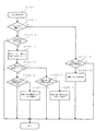
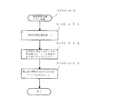
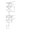
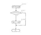
始動入賞口検出処理(S104)では、図7に示すように、前記上側始動入賞口41あるいは下側始動入賞口42への入賞が検出されたか判断され(S104−1)、入賞が検出されていない場合には前記普通図柄変動開始用ゲート55への遊技球通過が検出されたか判断される(S104−2)。前記普通図柄変動開始用ゲート55への遊技球通過が検出されていない場合には、この始動入賞口検出処理(S104)が終了する。一方、前記普通図柄変動開始用ゲート55への遊技球通過が検出された場合には、前記普通図柄保留球数が4以上か判断され(S104−3)、4以上の場合にはこの始動入賞口検出処理(S104)が終了する。一方、前記普通図柄保留球数が4未満であれば普通図柄保留球数に1加算され(S104−4)、普通図柄乱数値が取得され、取得した普通図柄乱数値が主制御基板200のRAMにおける対応する領域に記憶する普通図柄乱数取得処理が行われ(S104−5)、この始動入賞口検出処理(S104)が終了する。
In the start winning opening detection process (S104), as shown in FIG. 7, it is determined whether a winning to the upper start winning opening 41 or the lower start winning opening 42 is detected (S104-1), and a winning is detected. If not, it is determined whether or not the game ball passage to the normal symbol variation start gate 55 is detected (S104-2). When the passing of the game ball to the normal symbol variation start gate 55 is not detected, the start winning opening detection process (S104) is ended. On the other hand, when the passing of the game ball to the normal symbol variation start gate 55 is detected, it is determined whether the number of the normal symbol holding balls is 4 or more (S104-3). The mouth detection process (S104) ends. On the other hand, if the number of the normal symbol reserved balls is less than 4, 1 is added to the number of the normal symbol reserved balls (S104-4), the normal symbol random number value is acquired, and the acquired normal symbol random number value is stored in the RAM of the
前記S104−1で前記上側始動入賞口41あるいは下側始動入賞口42への入賞が検出されたと判断されると、前記特別図柄保留球数が4以上か判断され(S104−6)、4以上の場合にはこの始動入賞口検出処理(S104)が終了する。一方、前記特別図柄保留球数が4未満であれば、特別図柄保留球数に1加算され(S104−7)、大当たり乱数値、大当たり図柄乱数値、リーチ乱数値、変動パターン乱数値等の特別図柄関係乱数を取得して主制御基板200のRAMの対応する領域に記憶する特別図柄関係乱数取得処理が行われ(S104−8)、この始動入賞口検出処理(S104)が終了する。
If it is determined in S104-1 that a winning in the upper starting winning port 41 or the lower starting winning port 42 is detected, it is determined whether the number of special symbol reservation balls is 4 or more (S104-6). In this case, the start winning opening detection process (S104) ends. On the other hand, if the number of special symbol reserve balls is less than 4, the special symbol reserve ball number is incremented by 1 (S104-7), and special jackpot random numbers, jackpot symbol random values, reach random numbers, fluctuation pattern random numbers, etc. A special symbol related random number acquisition process for acquiring the symbol related random number and storing it in the corresponding area of the RAM of the
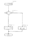
普通動作処理(S105)では、図8に示すように、まず前記下側始動入賞口42が開放中か確認される(S105−1)。前記下側始動入賞口42が閉鎖中であれば、普通図柄保留球数が0か確認され(S105−2)、0であればこの普通動作処理(S105)が終了する。一方、普通図柄保留球数が0では無い場合には、前記始動入賞口検出処理(S104)の普通図柄乱数取得処理(S104−5)で取得されて主制御基板200のRAMに記憶されている取得普通図柄乱数値が読み出され(S105−3)、現在確変中(確変フラグがON)か確認される(S105−4)。確変中ではない場合、前記取得普通図柄乱数値が低確率状態の普通図柄当たり成立数値と対比されて両者が一致するか確認され、一致する場合には低確率状態での普通図柄当たりとなり、一致しない場合には外れと判断される(S105−5)。外れの場合には、この普通動作処理(S105)が終了し、一方、普通図柄当たりの場合には、下側始動入賞口42を開放時間1秒、開放回数1回で開放する始動入賞口開放処理1が行われ(S105−6)、その後にこの普通動作処理(S105)が終了する。それに対して、S105−4で確変中と判断されると、前記取得普通図柄乱数値が高確率状態の普通図柄たり成立数値と対比されて両者が一致するか確認され、一致する場合には高確率状態での普通図柄当たりとなり、一致しない場合には外れと判断される(S105−7)。外れの場合には、この普通動作処理(S105)が終了し、一方、普通図柄当たりの場合には、下側始動入賞口42を開放時間2秒、開放回数3回で開放する始動入賞口開放処理2が行われ(S105−8)、その後にこの普通動作処理(S105)が終了する。
In the normal operation process (S105), as shown in FIG. 8, it is first confirmed whether or not the lower start winning opening 42 is open (S105-1). If the lower start winning opening 42 is closed, it is confirmed that the number of normal symbol reserved balls is 0 (S105-2), and if it is 0, the normal operation process (S105) is ended. On the other hand, when the number of normal symbol holding balls is not 0, it is acquired by the normal symbol random number acquisition process (S104-5) of the start winning opening detection process (S104) and stored in the RAM of the
また、S105−1で下側始動入賞口42が開放中と判断されると、下側始動入賞口42の開放時間が経過(終了)したか確認され(S105−9)、始動入賞口開放時間が経過していない場合には、この普通動作処理(S105)が終了し、一方、始動入賞口開放時間が経過した場合には、下側始動入賞口42を閉鎖する処理が行われ(S105−10)、その後にこの普通動作処理(S105)が終了する。 If it is determined in S105-1 that the lower start winning opening 42 is being opened, it is confirmed whether or not the opening time of the lower start winning opening 42 has passed (finished) (S105-9). When the time has not elapsed, the normal operation process (S105) ends. On the other hand, when the start winning opening opening time has elapsed, a process for closing the lower starting winning opening 42 is performed (S105-). 10) Thereafter, the normal operation process (S105) is completed.
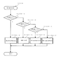
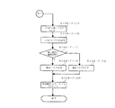
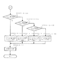
特別動作処理(S106)では、図9に示すように、特別動作ステータスが1〜4の何れであるか判断される(S106−1〜S106−3)。前記特別動作ステータスが1の場合には特別図柄待機処理(S106−4)が行われ、前記特別動作ステータスが2の場合には変動中処理(S106−5)が行われ、前記特別動作ステータスが3の場合には特別図柄確定処理(S106−6)が行われ、前記特別動作ステータスが4の場合には特別電動役物処理(S106−7)が行われる。 In the special operation process (S106), as shown in FIG. 9, it is determined which of the special operation status is 1 to 4 (S106-1 to S106-3). When the special operation status is 1, a special symbol standby process (S106-4) is performed, and when the special operation status is 2, a changing process (S106-5) is performed, and the special operation status is In the case of 3, a special symbol confirmation process (S106-6) is performed, and in the case where the special operation status is 4, a special electric accessory process (S106-7) is performed.
特別動作ステータスが1の場合に行われる特別図柄待機処理(S106−4)では、図10に示すように、特別図柄保留球数が0か否か判断され(S106−4−1)、特別図柄保留球数が0の場合には前記表示装置10が特別図柄の変動中ではない待機画面(待ち受け画面)中か否か判断され(S106−4−9)、待機画面(待ち受け画面)中であれば、この特別図柄待機処理(S106−4)が終了する。一方、待機画面(待ち受け画面)中ではない場合には前記表示装置10を待機画面(待ち受け画面)にするための待機画面設定処理が行われ(S106−4−10)、次に待機中にセットされ(S106−4−11)、その後にこの特別図柄待機処理(S106−4)が終了する。なお、待機画面にする設定処理は、この設定処理がなされてから所定時間の間、前記上側始動入賞口41あるいは下側始動入賞口42に遊技球が入賞しない場合に、待ち受け画面をセットするコマンドが出力されるようにする処理である。
それに対して前記S106−4−1で特別図柄保留球数が0ではないと判断された場合には、特別図柄大当たり判定処理(S106−4−2)が行われる。
In the special symbol standby process (S106-4) performed when the special operation status is 1, as shown in FIG. 10, it is determined whether or not the number of special symbol reservation balls is 0 (S106-4-1), and the special symbol is determined. When the number of held balls is 0, it is determined whether or not the
On the other hand, if it is determined in S106-4-1 that the number of special symbol reservation balls is not 0, special symbol jackpot determination processing (S106-4-2) is performed.
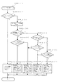
特別図柄大当たり判定処理(S106−4−2)では、図11に示すように、まず、前記始動入賞口検出処理(S104)の特別図柄関係乱数取得処理(S104−8)で取得されて主制御基板200のRAMに記憶されている大当たり乱数値が読み出され(S106−4−2−1)、次に現在確変中(高確率状態)か確認される(S106−4−2−2)。確変中か否かは、確変フラグがONの場合に確変中と判断され、一方確変フラグがOFFの場合に確変中ではない低確率状態と判断される。確変中ではない低確率状態の場合、前記取得大当たり乱数値が低確率状態時の大当たり成立数値と対比されて両者が一致するか確認され、一致する場合には低確率状態での大当たりとなり、一致しない場合には外れと判断される(S106−4−2−3)。外れの場合には、この特別図柄大当たり判定処理(S106−4−2)が終了し、一方、大当たりの場合には、大当たりフラグがONにセットされ(S106−4−2−5)、その後にこの特別図柄大当たり判定処理(S106−4−2)が終了する。それに対して、S106−4−2−2で確変中(高確率状態)と判断されると、前記取得大当たり乱数値が高確率状態時の大当たり成立数値と対比されて両者が一致するか確認され、一致する場合には高確率状態での大当たりとなり、一致しない場合には外れと判断される(S106−4−2−4)。外れの場合には、この特別図柄大当たり判定処理(S106−4−2)が終了し、一方、大当たりの場合には、大当たりフラグがONにセットされ(S106−4−2−5)、その後にこの特別図柄大当たり判定処理(S106−4−2)が終了する。この特別図柄大当たり判定処理(S106−4−2)は、当否判定手段に相当する。
In the special symbol jackpot determination process (S106-4-2), as shown in FIG. 11, first, it is acquired by the special symbol-related random number acquisition process (S104-8) of the start winning opening detection process (S104) and is subjected to the main control. The jackpot random number value stored in the RAM of the
前記特別図柄大当たり判定処理(S106−4−2)の次に特別図柄選択処理(S106−4−3)が行われる。
特別図柄選択処理(S106−4−3)では、前記表示装置10で停止表示する特別図柄の組合せ(判定結果の表示図柄)が決定され、決定された図柄の元となる図柄データが、前記出力処理(S101)でサブ制御基板205へ送信されるようにここでセットされる。なお、サブ制御基板205の処理では、受信した図柄データに基づく特別図柄の組合せが選択されて、前記表示制御基板210へ出力される。
Following the special symbol jackpot determination process (S106-4-2), a special symbol selection process (S106-4-3) is performed.
In the special symbol selection process (S106-4-3), a combination of special symbols to be stopped and displayed on the display device 10 (display symbol of the determination result) is determined, and the symbol data that is the basis of the determined symbol is the output It is set here so as to be transmitted to the
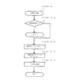
前記特別図柄選択処理(S106−4−3)では、図12に示すように、まず大当たりフラグがONか判断され(S106−4−3−1)、大当たりフラグがON、すなわち大当たりの場合には前記大当たり図柄乱数に基づく特別図柄が停止特別図柄としてセットされる(S106−4−3−2)。一方、大当たりフラグがONではない、すなわち外れの場合には、特別図柄データ乱数値(特別図柄データ1・特別図柄データ2・特別図柄データ3)を取得し(S106−4−3−3)、前記特別図柄データ1と特別図柄データ2と特別図柄データ3の乱数値が全て一致しているか判断され(S106−4−3−4)、一致している場合にはリーチ乱数値がリーチ成立数値と一致しているか判断される(S106−4−3−5)。リーチ乱数値がリーチ成立数値と一致している場合にはリーチ有りとなり、前記特別図柄データ1の乱数値に割り当てられている特別図柄が停止左特別図柄、特別図柄データ2の乱数値に1加算した乱数値に割り当てられている特別図柄が停止中特別図柄、特別図柄データ3の乱数値に割り当てられている特別図柄が停止右特別図柄にセットされる(S106−4−3−6)。一方、リーチ乱数値がリーチ成立数値と一致していない場合にはリーチ無しとなり、前記特別図柄データ1の乱数値に割り当てられている特別図柄が停止左特別図柄、特別図柄データ2の乱数値に割り当てられている特別図柄が停止中特別図柄、特別図柄データ3の乱数値に1加算した乱数値に割り当てられている特別図柄が停止右特別図柄にセットされる(S106−4−3−7)。
In the special symbol selection process (S106-4-3), as shown in FIG. 12, it is first determined whether or not the jackpot flag is ON (S106-4-3-1). A special symbol based on the jackpot symbol random number is set as a stop special symbol (S106-4-3-3). On the other hand, if the jackpot flag is not ON, that is, if it is off, a special symbol data random value (
前記S106−4−3−4で特別図柄データ1と2と3の乱数値が一致していないと判断された場合には、特別図柄データ1と3の乱数値が一致しているか判断される(S106−4−3−8)。特別図柄データ1と3の乱数値が一致している場合には、リーチ乱数値がリーチ成立数値と一致しているか判断される(S106−4−3−9)。リーチ乱数値がリーチ成立数値と一致している場合にはリーチ有りとなり、前記特別図柄データ1の乱数値に割り当てられている特別図柄が停止左特別図柄、特別図柄データ2の乱数値に割り当てられている特別図柄が停止中特別図柄、特別図柄データ3の乱数値に割り当てられている特別図柄が停止右特別図柄にセットされる(S106−4−3−10)。一方、リーチ乱数値がリーチ成立数値と一致していない場合にはリーチ無しとなり、前記特別図柄データ1の乱数値に割り当てられている特別図柄が停止左特別図柄、特別図柄データ2の乱数値に割り当てられている特別図柄が停止中特別図柄、特別図柄データ3の乱数値に1加算した乱数値に割り当てられている特別図柄が停止右特別図柄にセットされる(S106−4−3−7)。
If it is determined in S106-4-3-3-4 that the random numbers of the
前記S106−4−3−8で特別図柄データ1と3の乱数値が一致していない、すなわち特別図柄データ1,2,3が全て異なると判断された場合には、リーチ乱数値がリーチ成立数値と一致しているか判断される(S106−4−3−11)。リーチ乱数値がリーチ成立数値と一致している場合にはリーチ有りとなり、前記特別図柄データ3の乱数値に割り当てられている特別図柄が停止左特別図柄と停止右特別図柄にセットされると共に、特別図柄データ3の乱数値に1加算した乱数値に割り当てられている特別図柄が停止中特別図柄にセットされる(S106−4−3−12)。一方、リーチ乱数値がリーチ成立数値と一致していない場合にはリーチ無しとなり、前記特別図柄データ1の乱数値に割り当てられている特別図柄が停止左特別図柄、特別図柄データ2の乱数値に割り当てられている特別図柄が停止中特別図柄、特別図柄データ3の乱数値に割り当てられている特別図柄が停止右特別図柄にセットされる(S106−4−3−10)。なお、前記特別図柄選択処理(S106−4−3)は、図柄データ決定手段に相当し、ここで決定された図柄データがサブ制御基板205に送信されて、サブ制御基板205の処理で図柄データに従って図柄が設定される。本実施例では、表示装置に表示する図柄を主制御基板200で選択しているが、サブ制御基板205で決定してもよいとする。また、主制御基板200で決定した図柄を表示装置と異なる他の表示装置で表示し、主制御基板200で決定した図柄の図柄データに基づいて表示装置に表示する図柄をサブ制御基板205で決定してもよいとする。その際は、主制御基板200とサブ制御基板205による表示方法が異なるが、サブ制御基板205が主制御基板200のデータに基づいて図柄を決定していれば互いの図柄の認識が異なっていても良いとする。
If it is determined in S106-4-3-8 that the random numbers of the
前記特別図柄選択処理(S106−4−3)の次に特別図柄変動パターン選択処理(S106−4−4)が行われる。
特別図柄変動パターン選択処理(S106−4−4)は、変動パターン選択手段に相当し、当否判定結果に基づき複数の変動パターンテーブルから一つのテーブル(変動パターンテーブル)が選択され、選択した変動パターンテーブルから前記変動パターン乱数値により一つの変動パターン(変動コマンド)が選択される。
After the special symbol selection process (S106-4-3), a special symbol variation pattern selection process (S106-4-4) is performed.
The special symbol variation pattern selection process (S106-4-4) corresponds to variation pattern selection means, and one table (variation pattern table) is selected from a plurality of variation pattern tables based on the determination result, and the selected variation pattern is selected. One variation pattern (variation command) is selected from the table by the variation pattern random value.
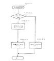
前記特別図柄変動パターン選択処理(S106−4−4)では、図13及び図14に示すように、まず、確変中(高確率状態)か否か判定される(S106−4−4−1)。確変中ではない通常状態(低確率状態)の場合には、大当たりフラグがON(大当たり)か否か判定される(S106−4−4−2)。大当たりフラグがON(大当たり)の場合には、通常当たり変動パターンテーブルから変動パターン乱数値に応じて変動パターンが選択される(S106−4−4−3)。 In the special symbol variation pattern selection process (S106-4-4), as shown in FIGS. 13 and 14, it is first determined whether or not the probability variation is in progress (high probability state) (S106-4-4-1). . In the case of a normal state (low probability state) that is not under certain change, it is determined whether or not the big hit flag is ON (big hit) (S106-4-4-2). When the big hit flag is ON (big hit), a fluctuation pattern is selected from the normal hit fluctuation pattern table according to the fluctuation pattern random value (S106-4-4-3).
一方、S106−4−4−2で大当たりフラグがOFF(外れ)と判定されると、記憶されていたリーチ乱数値が読み出されてリーチ成立数値と一致するか判定され(S106−4−4−4)、一致する場合には通常リーチハズレ変動パターンテーブルから変動パターン乱数値に応じて変動パターンが選択され(S106−4−4−5)、一致しない場合には通常ハズレ変動パターンテーブルから変動パターン乱数値に応じて変動パターンが選択される(S106−4−4−6)。 On the other hand, if it is determined in S106-4-4-2 that the jackpot flag is OFF (disconnected), the stored reach random number value is read out to determine whether it matches the reach establishment value (S106-4-4). -4) If they match, the variation pattern is selected from the normal reach variation pattern table according to the variation pattern random value (S106-4-4-5). If they do not match, the variation pattern is selected from the normal variation pattern table. A variation pattern is selected according to the random value (S106-4-4-6).
前記S106−4−4−1で確変中(高確率状態)と判断されると、大当たりフラグがON(大当たり)か否か判断される(S106−4−4−7)。大当たりフラグがON(大当たり)の場合には、確変当たり変動パターンテーブルから変動パターン乱数値に応じて変動パターンが選択される(S106−4−4−8)。 If it is determined in S106-4-4-1 that the probability change is in progress (high probability state), it is determined whether or not the big hit flag is ON (big hit) (S106-4-4-7). When the big hit flag is ON (big hit), a variation pattern is selected from the variation pattern table for probability variation according to the variation pattern random value (S106-4-4-8).
一方、S106−4−4−7で大当たりフラグがOFF(外れ)と判定されると、記憶されているリーチ乱数値が読み出されてリーチ成立数値と一致するか判定され、一致する場合には確変リーチハズレ変動パターンテーブルから変動パターン乱数値に応じて変動パターンが選択され(S106−4−4−10)、一致しないと判定された場合には確変ハズレ変動パターンテーブルから変動パターン乱数値に応じて変動パターンが選択される(S106−4−4−11)。 On the other hand, if it is determined in S106-4-4-7 that the jackpot flag is OFF (disconnected), the stored reach random number value is read out to determine whether it matches the reach establishment value. A variation pattern is selected from the probability variation reach variation pattern table according to the variation pattern random value (S106-4-4-10), and if it is determined that they do not match, the probability variation from the variation pattern table according to the variation pattern random value is determined. A variation pattern is selected (S106-4-4-11).
前記変動パターンの選択後、選択した変動パターンの変動コマンドが出力バッファに格納され(S106−4−4−12)、次にその他の処理が行われ(S106−4−4−13)、その後にこの特別図柄変動パターン選択処理(S106−4−4)が終了する。 After selecting the variation pattern, the variation command of the selected variation pattern is stored in the output buffer (S106-4-4-12), and then other processing is performed (S106-4-4-13). This special symbol variation pattern selection process (S106-4-4) is completed.
前記特別図柄変動パターン選択処理(S106−4−4)の次に特別図柄乱数シフト処理(S106−4−5)が行われる。
特別図柄乱数シフト処理(S106−4−5)では、前記RAMの特別図柄保留球数のデータ記憶領域において、ロード(読み出し)順位一位のアドレスの記憶領域に記憶されていた特別図柄保留球数のデータが、先の処理によりロードされて空席となることに起因して、ロード順位が二位以降のアドレスに記憶されている特別図柄保留球数のデータについて、ロード順位を一つずつ繰り上げるアドレスのシフトが行われる。具体的には、図15に示すように、まず、前記主制御基板200のRAMに記憶されている前記特別図柄保留球数から1減算(例えば保留球数2のものは1にされ、3のものは2にされる等)され(S106−4−5−1)、次に各保留球数に対応するデータが各保留球数から1減算した保留球数のRAMアドレスにシフトされ(S106−4−5−2)、続いて最上位(ロード順位が最後、本実施例では4個目)の特別図柄保留球数に対応するRAMアドレスに0がセットされる(S106−4−5−3)。
After the special symbol variation pattern selection process (S106-4-4), a special symbol random number shift process (S106-4-5) is performed.
In the special symbol random number shift process (S106-4-5), in the data storage area of the special symbol reservation ball number in the RAM, the number of special symbol reservation balls stored in the storage area of the load (reading) ranking first place. Due to the fact that this data is loaded in the previous process and becomes vacant, the address that advances the loading order one by one with respect to the data of the number of special symbol holding balls stored in the second and subsequent addresses. Shifts are made. Specifically, as shown in FIG. 15, first, 1 is subtracted from the number of special symbol reserved balls stored in the RAM of the main control board 200 (for example, the number of reserved balls of 2 is set to 1 and 3 (S106-4-5-1), and the data corresponding to each number of reserved balls is shifted to the RAM address of the number of reserved balls obtained by subtracting 1 from each number of reserved balls (S106-). 4-5-2) Subsequently, 0 is set to the RAM address corresponding to the number of special symbol reservation balls (the last in the loading order, the fourth in this embodiment) (S106-4-5-3). ).
前記特別図柄乱数シフト処理(S106−4−5)に次いで、特別図柄変動開始処理(S106−4−6)が行われる。特別図柄変動開始処理(S106−4−6)では、特別図柄の変動開始に必要な処理が行われる。
前記特別図柄変動開始処理(S106−4−6)の次に、特別動作ステータスが2に設定され(S106−4−7)、待機中が解除され(S106−4−8)、前記特別図柄待機処理(S106−4)が終了する。
Subsequent to the special symbol random number shift process (S106-4-5), a special symbol variation start process (S106-4-6) is performed. In the special symbol variation start process (S106-4-6), processing necessary for starting the variation of the special symbol is performed.
After the special symbol variation start process (S106-4-6), the special operation status is set to 2 (S106-4-7), the waiting state is canceled (S106-4-8), and the special symbol standby is performed. The process (S106-4) ends.
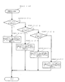
前記特別動作ステータスが2の場合に行われる変動中処理(S106−5)では図16に示すように、まず特別図柄の変動時間(変動パターンの変動時間)が終了したか否か判断され(S106−5−1)、変動時間が終了していなければこの変動中処理(S106−5)が終了する。一方、変動時間が終了していれば変動停止コマンドがセットされる(S106−5−2)。続いて特別動作ステータスが3にセットされ(S106−5−3)、その他必要な処理(S106−5−4)が行われた後に、この変動中処理(S106−5)が終了する。 In the changing process (S106-5) performed when the special operation status is 2, as shown in FIG. 16, it is first determined whether or not the special symbol change time (change pattern change time) has ended (S106). -5-1) If the change time has not ended, the changing process (S106-5) is ended. On the other hand, if the fluctuation time has ended, a fluctuation stop command is set (S106-5-2). Subsequently, after the special operation status is set to 3 (S106-5-3) and other necessary processing (S106-5-4) is performed, this in-fluctuation processing (S106-5) ends.
前記特別動作ステータスが3の場合に行われる特別図柄確定処理(S106−6)では図17に示すように、まず大当たりフラグがONか否か、すなわち大当たりか否か判断される(S106−6−1)。大当たりフラグがON、すなわち大当たりの場合には、大当たりコマンドが出力バッファに格納され(S106−6−2)、特別動作ステータスが4にセットされた(S106−6−3)後、この特別図柄確定処理(S106−6)が終了する。一方、大当たりフラグがOFF、すなわち外れの場合には、特別動作ステータスが1にセットされ(S106−6−4)、この特別図柄確定処理(S106−6)が終了する。 In the special symbol confirmation process (S106-6) performed when the special operation status is 3, as shown in FIG. 17, it is first determined whether or not the big hit flag is ON, that is, whether or not the big hit flag is set (S106-6). 1). When the jackpot flag is ON, that is, when the jackpot is successful, the jackpot command is stored in the output buffer (S106-6-2), and the special operation status is set to 4 (S106-6-3). The process (S106-6) ends. On the other hand, if the jackpot flag is OFF, that is, it is off, the special operation status is set to 1 (S106-6-4), and this special symbol confirmation process (S106-6) is completed.
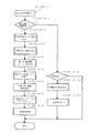
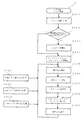
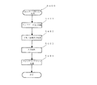
前記特別動作ステータスが4の場合に行われる特別電動役物処理(S106−7)は、特別遊技期間実行手段(大当たり遊技実行手段)に相当する。特別電動役物処理(S106−7)では、図18及び図19に示すように、確変フラグがOFFにされ(S106−7−1)、前記表示装置10で大当たりオープニング演出が実施されたか確認される(S106−7−2)。大当たりオープニング演出が実施されていない場合には、大当たりオープニング演出が実行され(S106−7−3)、その後に大当たり終了フラグがON(大当たり遊技終了)か否か判断される(S106−7−4)。一方、大当たりオープニング演出が実施済みの場合には、次に大当たり終了フラグがON(大当たり遊技終了)か否か判断される(S106−7−4)。
The special electric accessory process (S106-7) performed when the special operation status is 4 corresponds to special game period execution means (big hit game execution means). In the special electric accessory processing (S106-7), as shown in FIGS. 18 and 19, the probability variation flag is turned off (S106-7-1), and it is confirmed whether the
大当たり終了フラグがONではない、すなわち大当たり遊技終了ではない場合には現在大入賞口45が開放中か否か判断され(S106−7−5)、開放中ではなく閉鎖中の場合には大入賞口45の開放時間か否か判断される(S106−7−6)。大入賞口45の開放時間の場合には大入賞口の開放処理が行われ(S106−7−7)、その後にこの特別電動役物処理(S106−7)が終了する。それに対して大入賞口45の開放時間となっていないときには、この特別電動役物処理(S106−7)が終了する。 When the jackpot end flag is not ON, that is, when the jackpot game is not ended, it is determined whether or not the big prize opening 45 is currently open (S106-7-5). It is determined whether or not it is the opening time of the mouth 45 (S106-7-6). In the case of the opening time of the special winning opening 45, the special winning opening process is performed (S106-7-7), and then the special electric accessory process (S106-7) is ended. On the other hand, when it is not the opening time of the special winning opening 45, the special electric accessory processing (S106-7) is ended.
一方、前記S106−7−5で大入賞口45が開放中と判断されると、大入賞口閉鎖時間か(S106−7−8)、若しくは大入賞口45に10個遊技球が入賞(S106−7−9)の何れかであるか否か判断され、何れでもない場合にはそのままこの特別電動役物処理(S106−7)が終了し、それに対して大入賞口閉鎖時間、若しくは大入賞口45に10個遊技球が入賞の何れかである場合には、大入賞口閉鎖処理(S106−7−10)が実行され、その後にラウンド終了時間か確認される(S106−7−11)。ラウンド終了時間ではない場合には、そのままこの特別電動役物処理(S106−7)が終了し、それに対してラウンド終了時間の場合には、ラウンドカウンタの値から1減算する処理(S106−7−12)が行われる。なお、前記大入賞口閉鎖処理(S106−7−10)では、大入賞口閉鎖のコマンドが出力バッファにセットされる。続いて、ラウンドカウンタが0か否か判断され(S106−7−13)、ラウンドカウンタが0ではない場合には、そのままこの特別電動役物処理(S106−7)が終了し、それに対してラウンドカウンタが0の場合には、大当たり終了処理と大当たり終了フラグがONにする処理(S106−7−14)が行われた後、この特別電動役物処理(S106−7)が終了する。なお、前記大当たり終了処理では、エンディングの準備が行われる。 On the other hand, if it is determined in S106-7-5 that the big prize opening 45 is open, it is the big prize opening closing time (S106-7-8), or 10 game balls are won in the big prize opening 45 (S106). -7-9) is determined, and if it is none, the special electric accessory processing (S106-7) is finished as it is, and the closing time for the big prize opening or the big prize is received. When ten game balls are won in the mouth 45, a big winning mouth closing process (S106-7-10) is executed, and then it is confirmed whether the round end time (S106-7-11). . If it is not the round end time, the special electric accessory processing (S106-7) is finished as it is, and if it is the round end time, 1 is subtracted from the value of the round counter (S106-7-). 12) is performed. In the special winning opening closing process (S106-7-10), a special winning opening closing command is set in the output buffer. Subsequently, it is determined whether or not the round counter is 0 (S106-7-13). If the round counter is not 0, the special electric accessory processing (S106-7) is finished as it is, and the round counter is processed. When the counter is 0, after the jackpot end process and the process of turning on the jackpot end flag (S106-7-14) are performed, the special electric accessory process (S106-7) is ended. In the jackpot end process, preparation for ending is performed.
それに対し、前記S106−7−4で大当たり終了フラグがON、すなわち大当たり終了と判断されると、大当たり終了フラグをOFFにセットする処理(S106−7−15)と、大当たりフラグをOFFにする処理(S106−7−16)が行われ、次に停止特別図柄が確変図柄(奇数のぞろ目)であるか確認され(S106−7−17)、停止特別図柄が確変図柄である場合には確変フラグがONにされ(S106−7−18)、一方、停止特別図柄が確変図柄ではなく通常図柄(偶数のぞろ目)である場合には確変フラグがOFFにされ(S106−7−19)、その後に特別動作ステータスが1にセットされ(S106−7−20)、この特別電動役物処理(S106−7)が終了する。 On the other hand, if it is determined in S106-7-4 that the jackpot end flag is ON, that is, if the jackpot end flag is determined, the process of setting the jackpot end flag to OFF (S106-7-15) and the process of turning the jackpot flag OFF. (S106-7-16) is performed, and then it is confirmed whether or not the stop special symbol is a probability variable symbol (odd tick) (S106-7-17), and if the special stop symbol is a probability variable symbol If the probability variation flag is turned on (S106-7-18), on the other hand, if the special symbol for stoppage is not a probability variation symbol but a normal symbol (an even number), the probability variation flag is turned off (S106-7-19). Then, the special operation status is set to 1 (S106-7-20), and this special electric accessory processing (S106-7) is completed.
前記特別動作処理(S106)の次に保留球数処理(S107)が行われる。保留球数処理(S107)では、図20に示すように現在の保留球数がロードされ(S107−1)、保留球数が出力バッファにセットされる(S107−2)。 Following the special operation process (S106), a reserved ball number process (S107) is performed. In the reserved ball number process (S107), as shown in FIG. 20, the current reserved ball number is loaded (S107-1), and the reserved ball number is set in the output buffer (S107-2).
前記保留球数処理(S107)の次に電源断監視処理(S108)が行われる。電源断監視処理(S108)では、図21に示すように、電源断信号が入力したか判断され(S108−1)、電源断信号が入力していない場合にはこの電源断監視処理(S108)が終了する。一方、電源断信号が入力している場合には、現在のデータ(遊技状態)が前記主制御基板200のRAMに記憶され(S108−2)、その後電源断フラグがONに設定され(S108−3)、この電源断監視処理(S108)が終了する。なお、前記主制御基板200のRAMに記憶されるデータ(遊技状態)としては、大きく分けて、表示待機中、図柄変動中、図柄確定表示中、大当たり遊技中のデータがあり、さらにそれぞれ確変状態(高確率状態)と通常状態(低確率状態)のデータがある。
A power-off monitoring process (S108) is performed after the reserved ball number process (S107). In the power-off monitoring process (S108), as shown in FIG. 21, it is determined whether a power-off signal is input (S108-1). If no power-off signal is input, this power-off monitoring process (S108). Ends. On the other hand, when the power-off signal is input, the current data (game state) is stored in the RAM of the main control board 200 (S108-2), and then the power-off flag is set ON (S108-). 3) The power-off monitoring process (S108) ends. The data (game state) stored in the RAM of the
前記電源断監視処理(S108)の次にその他の処理(S109)が行われる。その他の処理(S109)では、遊技制御に必要なその他の処理が行われる。 Following the power-off monitoring process (S108), other processes (S109) are performed. In other processing (S109), other processing necessary for game control is performed.
前記サブ制御基板(サブ制御装置)205が行う処理について説明する。
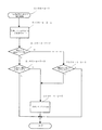
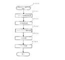
前記サブ制御基板205が行うサブ制御メイン処理Jでは、図22に示すように、遊技機1の電源投入時にサブ制御基板205においてCPU初期化処理が行われる(S201)。CPU初期化処理では、外部INT割り込み(受信割り込み)処理(S300)、2msタイマ割り込み処理(S400)、10msタイマ割り込み処理(S500)に対する設定等が行われる。次に、電源断信号がONでRAMの内容が正常か判断される(S202)。電源断信号がONでなかったり、電源断信号がONでRAMの内容が正常でない場合など電源断信号の状態とRAMの内容正常の両方を満たさない場合は、RAMの初期化が行われ(S203)、その後にウオッチドッグタイマカウンタ1、2の初期化が行われる(S204)。一方、電源断信号ONとRAMの内容正常の両方を満たす場合には、RAMの初期化を行うことなくウオッチドッグタイマカウンタ1、2の初期化が行われる(S204)。S201〜S204の処理は、電源投入時の1順目にのみ実行され、その後は実行されることがない。
Processing performed by the sub control board (sub control device) 205 will be described.
In the sub-control main process J performed by the
ウオッチドッグタイマカウンタ1、2の初期化(S204)の後、ループ処理で割り込み禁止(S205)、乱数シード更新(S206)、コマンド送信処理(S207)、ウオッチドッグタイマカウンタ1初期化(S208)、割り込み許可(S209)が行われる。また、ループ処理の間に、外部INT割り込み処理(S300)、2msタイマ割り込み処理(S400)、10msタイマ割り込み処理(S500)が行われる。
After initialization of watchdog timer counters 1 and 2 (S204), interrupt processing is disabled by loop processing (S205), random number seed update (S206), command transmission processing (S207),
割り込み禁止(S205)では、割り込みが入っても割り込みを禁止する。
乱数シード更新(S206)では、サブ制御基板205に設けられているステップアップ予告乱数、ステップ数乱数等の乱数更新が行われる。
コマンド送信処理(S207)では、サブ制御処理においてセットされた各種のコマンドが対応する基板、装置等に送信される。
ウオッチドッグタイマカウンタ1初期化(S208)では、ウオッチドッグタイマカウンタ1の値が初期化される。
割り込み許可(S209)では、割り込みの実行を許可する。
In the interrupt prohibition (S205), even if an interrupt occurs, the interrupt is prohibited.
In the random number seed update (S206), random numbers such as a step-up notice random number and a step number random number provided in the
In the command transmission process (S207), various commands set in the sub-control process are transmitted to the corresponding substrate, apparatus, and the like.
In the initialization of the watchdog timer counter 1 (S208), the value of the
In interrupt permission (S209), execution of the interrupt is permitted.
外部INT割り込み処理(S300)では、図23に示すように、前記主制御基板200からのストローブ(STB)信号がONか確認され(S301)、ストローブ信号がON、すなわち外部INT入力部にストローブ信号が入力されると、前記主制御基板200から出力されたコマンド(制御信号)の受信およびRAMへの格納が行われる(S302)。それに対し、ストローブ信号がONになっていなければ、その時点でこの外部INT割り込み処理(S300)が終了する。
In the external INT interrupt process (S300), as shown in FIG. 23, it is confirmed whether the strobe (STB) signal from the
2msタイマ割り込み処理(S400)では、図24に示すように、ランプデータ出力処理(S401)、SW/駆動出力処理(S402)、入力処理(S403)、ウォッチドッグタイマ処理(S404)が行われる。
ランプデータ出力処理(S401)では、10msタイマ割り込み処理で作成したランプデータの出力が行われる。
SW/駆動出力処理(S402)では、遊技ボタンスイッチ67の有効期間及び動作の出力が行われる。
入力処理(S403)では、スイッチのエッジデータ及びレベルデータの作成が行われる。
ウォッチドッグタイマ処理(S404)では、ウォッチドッグタイマのリセット設定が行われる。
In the 2 ms timer interrupt process (S400), as shown in FIG. 24, a lamp data output process (S401), a SW / drive output process (S402), an input process (S403), and a watchdog timer process (S404) are performed.
In the ramp data output process (S401), the ramp data created in the 10 ms timer interrupt process is output.
In the SW / drive output process (S402), the valid period and operation of the game button switch 67 are output.
In the input process (S403), switch edge data and level data are created.
In the watchdog timer process (S404), the watchdog timer is reset.
10msタイマ割り込み処理(S500)では、図25に示すように、スイッチ状態取得処理(S501)、音声制御処理(S502)、メインコマンド解析処理(S503)、SW処理(S504)、ランプ処理(S505)が行われる。 In the 10 ms timer interrupt process (S500), as shown in FIG. 25, the switch state acquisition process (S501), the voice control process (S502), the main command analysis process (S503), the SW process (S504), and the lamp process (S505). Is done.
スイッチ状態取得処理(S501)では、2msタイマ割り込み処理(S400)で作成されたスイッチデータが、10msタイマ割り込み処理用のスイッチデータとして格納される。
音声制御処理(S502)では、前記スピーカ38から発する音声のための処理が行われる。
In the switch state acquisition process (S501), the switch data created in the 2ms timer interrupt process (S400) is stored as switch data for the 10ms timer interrupt process.
In the sound control process (S502), a process for sound emitted from the
メインコマンド解析処理(S503)では、図26に示すように、前記主制御基板200から受信したコマンドが変動コマンドか確認され(S503−1)、変動コマンドとは異なるコマンドを受信している場合には、受信コマンドに対応した処理が行われ(S503−2)、その後にこのメインコマンド解析処理(S503)が終了する。一方、変動コマンドを受信している場合には、ステップアップ予告処理(S503−3)が行われ、その後にこのメインコマンド解析処理(S503)が終了する。
In the main command analysis process (S503), as shown in FIG. 26, it is confirmed whether the command received from the
ステップアップ予告処理(S503−3)では、図27及び図28に示すように、まずステップアップ予告(段階的表示予告)を行うか否かが決定される(S503−3−1)。S503−3−1の処理は、ステップアップ予告(段階的表示予告)を行うか否かを決定する予告決定手段に相当する。S503−3−1の予告決定手段の処理では、前記ステップアップ予告乱数値が取得され、取得されたステップアップ予告乱数値が‘0’〜‘49’の場合にステップアップ予告を行う(段階的表示予告有り)に決定され、一方、取得されたステップ予告乱数値が‘50’〜‘99’の場合にステップアップ予告を行わない(段階的表示予告無し)に決定される。ステップアップ予告を行わないと決定された場合には、このステップアップ予告処理(S503−3)が終了する。 In the step-up notice process (S503-3), as shown in FIGS. 27 and 28, it is first determined whether or not a step-up notice (stepped display notice) is to be performed (S503-3-1). The process of S503-3-1 corresponds to a notice determination unit that determines whether or not to perform a step-up notice (stepwise display notice). In the processing of the notice determination means in S503-3-1, the step-up notice random number value is acquired, and when the obtained step-up notice random number value is “0” to “49”, the step-up notice is performed (stepwise On the other hand, it is determined that the step-up advance notice is not performed (there is no step-by-step advance notice) when the obtained step advance random number value is “50” to “99”. When it is determined not to perform the step-up notice, this step-up notice process (S503-3) is ended.
一方、ステップ予告(段階的表示予告)を行うと決定された場合、次に当否判定結果が大当たりか確認される(S503−3−2)。大当たりの確認は、前記主制御基板200から受信した変動コマンドが大当たりの判定結果に基づいて選択された変動コマンド(通常当たり変動パターンの変動コマンド又は確変当たり変動パターンの変動コマンド)の場合には大当たりと判断される。大当たりの場合には、ステップ数乱数値が取得され、取得されたステップ数乱数値が‘0’〜‘9’、‘10’〜‘24’、‘25’〜‘84’、‘85’〜‘89’の何れの範囲か確認される(S503−3−3、S503−3−4、S503−3−5)。
On the other hand, when it is determined that the step advance notice (stepwise display advance notice) is to be performed, it is then confirmed whether the determination result is a big hit (S503-3-2). The jackpot confirmation is a jackpot when the variation command received from the
取得されたステップ数乱数値が‘0’〜‘9’の場合には、ステップ1(段階1)→ステップ2(段階2)の順に表示するステップ数(段階数)2に決定され、決定された順に表示する設定が行われる(S503−3−6)。また、取得されたステップ数乱数値が‘10’〜‘24’の場合には、ステップ1(段階1)→ステップ2(段階2)→ステップ3(段階3)の順に表示するステップ数(段階数)3に決定され、決定された順に表示する設定が行われる(S503−3−7)。また、取得されたステップ数乱数値が‘25’〜‘84’の場合には、ステップ1(段階1)→ステップ2(段階2)→ステップ3(段階3)→ステップ4(段階4)の順に表示するステップ数(段階数)4に決定され、決定された順に表示する設定が行われる(S503−3−8)。また、取得されたステップ数乱数値が‘85’〜‘89’の場合には、ステップ2(段階2)→ステップ4(段階4)の順に表示するステップ数(段階数)2に決定され、決定された順に表示する設定が行われる(S503−3−9)。 When the obtained step number random number value is “0” to “9”, the step number (stage number) 2 displayed in the order of step 1 (stage 1) → step 2 (stage 2) is determined and determined. The display is set in the order in which they are displayed (S503-3-6). Further, when the obtained step number random number value is “10” to “24”, the step number (stage) displayed in the order of step 1 (stage 1) → step 2 (stage 2) → step 3 (stage 3). The number is set to 3 and the setting for displaying in the determined order is made (S503-3-7). Further, when the obtained step number random number value is “25” to “84”, step 1 (stage 1) → step 2 (stage 2) → step 3 (stage 3) → step 4 (stage 4). The number of steps to be displayed in order (the number of stages) is determined to be 4, and setting to display in the determined order is performed (S503-3-8). When the obtained step number random number value is '85' to '89', the step number (stage number) 2 to be displayed in the order of step 2 (stage 2) → step 4 (stage 4) is determined. Settings to display in the determined order are made (S503-3-9).
一方、当否判定手段の判定結果が外れの場合には、ステップ数乱数値が取得され、取得されたステップ数乱数値が‘0’〜‘59’、‘60’〜‘79’、‘80’〜‘87’、‘88’〜‘89’の何れの範囲か確認される(S503−3−10、S503−3−11、S503−3−12)。 On the other hand, if the determination result of the success / failure determination unit is out of order, a step number random value is acquired, and the acquired step number random value is '0' to '59', '60' to '79', '80'. To '87' and '88' to '89' are confirmed (S503-3-10, S503-3-11, S503-3-12).
取得されたステップ数乱数値が‘0’〜‘59’の場合には、ステップ1(段階1)→ステップ2(段階2)の順に表示するステップ数(段階数)2に決定され、決定された順に表示する設定が行われる(S503−3−13)。また、取得されたステップ数乱数値が‘60’〜‘79’の場合には、ステップ1(段階1)→ステップ2(段階2)→ステップ3(段階3)の順に表示するステップ数(段階数)3に決定され、決定された順に表示する設定が行われる(S503−3−14)。また、取得されたステップ数乱数値が‘80’〜‘87’ の場合には、ステップ1(段階1)→ステップ2(段階2)→ステップ3(段階3)→ステップ4(段階4)の順に表示するステップ数(段階数)4に決定され、決定された順に表示する設定が行われる(S503−3−15)。また、取得されたステップ数乱数値が‘87’〜‘89’の場合には、ステップ2(段階2)→ステップ4(段階4)の順に表示するステップ数(段階数)2に決定され、決定された順に表示する設定が行われる(S503−3−16)。
前記S503−3−2〜S503−3−16は、段階的表示予告の段階数を当否判定手段の判定結果に基づいて選択する第1制御手段に相当する。
When the obtained step number random number value is “0” to “59”, the step number (stage number) 2 displayed in the order of step 1 (stage 1) → step 2 (stage 2) is determined and determined. The display is set in the order in which they are displayed (S503-3-13). In addition, when the obtained step number random number value is “60” to “79”, the step number (stage) displayed in the order of step 1 (stage 1) → step 2 (stage 2) → step 3 (stage 3). The number is set to 3 and the setting for displaying in the determined order is made (S503-3-14). Further, when the obtained step number random number value is '80' to '87', step 1 (stage 1) → step 2 (stage 2) → step 3 (stage 3) → step 4 (stage 4) The number of steps to be displayed in order (the number of stages) is determined to be 4, and setting to display in the determined order is performed (S503-3-15). In addition, when the obtained step number random number value is '87' to '89', the step number (stage number) 2 to be displayed in the order of step 2 (stage 2) → step 4 (stage 4) is determined. Settings to display in the determined order are made (S503-3-16).
The steps S503-3-2 to S503-3-16 correspond to first control means for selecting the number of stages for the stepwise display notice based on the determination result of the success / failure determination means.
前記大当たりの場合あるいは外れの場合におけるステップ数(段階数)が決定された後に段階数表示処理(S503−3−17)が行われ、その後にこのステップアップ予告処理(S503−3)が終了する。 After the number of steps (number of steps) in the case of the big hit or the case of losing is determined, a step number display process (S503-3-17) is performed, and then this step-up notice process (S503-3) is ended. .
段階数表示処理(S503−3−17)では、図29に示すように、ステップ1(段階1)の表示設定か、ステップ2(段階2)の表示設定か、ステップ3(段階3)の表示設定か、ステップ4(段階4)の表示設定かが順に確認される(S503−3−17−1、S503−3−17−2、S503−3−17−3)。 In the stage number display process (S503-3-17), as shown in FIG. 29, the display setting in step 1 (stage 1), the display setting in step 2 (stage 2), or the display in step 3 (stage 3). The setting and the display setting in step 4 (stage 4) are confirmed in order (S503-3-17-1, S503-3-17-2, S503-3-17-3).
ステップ1(段階1)の表示設定の場合には、前記表示装置10にキャラクターとしての前記ウインドウQ1を表示すると共に前記第1表示態様U1の数字として「1」を表示し、前記第2表示態様U2の装飾部のうち1個の装飾部u1の色を変更し、前記ウインドウQ1と前記第1表示態様の数字「1」と前記第2表示態様U2の装飾部u1〜u4を設定1の大きさ(本実施例では最小)に設定する処理が行われる(S503−3−17−4)。
In the case of the display setting in step 1 (stage 1), the window Q1 as a character is displayed on the
ステップ2(段階2)の表示設定の場合には、前記表示装置10にキャラクターとしての前記ウインドウQ2を表示すると共に前記第1表示態様U1の数字として「2」を表示し、前記第2表示態様U2の装飾部のうち2個の装飾部u1、u2の色を変更し、前記ウインドウQ2と前記第1表示態様の数字「2」と前記第2表示態様U2の装飾部u1〜u4を設定2の大きさ(設定1より大きい)に設定する処理が行われる(S503−3−17−5)。
In the case of the display setting in step 2 (stage 2), the window Q2 as a character is displayed on the
ステップ3(段階3)の表示設定の場合には、前記表示装置10にキャラクターとしての前記ウインドウQ3を表示すると共に前記第1表示態様U1の数字として「3」を表示し、前記第2表示態様U2の装飾部のうち3個の装飾部u1、u2、u3の色を変更し、前記ウインドウQ3と前記第1表示態様の数字「3」と前記第2表示態様U2の装飾部u1〜u4を設定3の大きさ(設定2より大きい)に設定する処理が行われる(S503−3−17−6)。
In the case of the display setting in step 3 (stage 3), the window Q3 as a character is displayed on the
ステップ4(段階4)の表示設定の場合には、前記表示装置10にキャラクターとしての前記ウインドウQ4を表示すると共に前記第1表示態様U1の数字として「4」を表示し、前記第2表示態様U2の装飾部のうち4個の装飾部u1、u2、u3、u4の色を変更し、前記ウインドウQ4と前記第1表示態様の数字「4」と前記第2表示態様U2の装飾部u1〜u4を設定4の大きさ(設定3よりも大きい)に設定する処理が行われる(S503−3−17−7)。
各ステップ(段階)の表示設定が行われた後、この段階数表示処理(S503−3−17)が終了する。
In the case of the display setting in step 4 (stage 4), the window Q4 as a character is displayed on the
After the display setting of each step (stage) is performed, this stage number display process (S503-3-17) ends.
なお、前記段階数表示処理(S503−17)は、複数のキャラクター(本実施例ではウインドウQ1〜Q4)の各々に、出現する段階(ステップ)を割り付ける第2制御手段と、複数のキャラクター(本実施例ではウインドウQ1〜Q4)を前記第2制御手段で割り付けられた段階(ステップ)で出現するように制御して前記表示装置(表示手段)10に表示する第3制御手段と、段階を示す数を少なくとも2つの表示態様(本実施例では第1表示態様U1と第2表示態様U2)で各々のキャラクター(本実施例ではウインドウQ1〜Q4)に付与して表示装置(表示手段)10に表示する第4制御手段に相当する。 The stage number display process (S503-17) includes a second control means for assigning an appearance stage (step) to each of a plurality of characters (windows Q1 to Q4 in this embodiment), and a plurality of characters (books). In the embodiment, the third control means for controlling the windows Q1 to Q4) to appear at the stage (step) assigned by the second control means and displaying them on the display device (display means) 10 is shown. A number is assigned to each character (windows Q1 to Q4 in this embodiment) in at least two display modes (first display mode U1 and second display mode U2 in this embodiment) to display device (display means) 10. This corresponds to the fourth control means for displaying.
SW処理(S504)では、遊技操作スイッチ67の有効時間(操作有効期間)及び動作の管理が行われる
ランプ処理(S505)では、出力するランプデータの作成及び演出時間の管理が行われる。
In the SW process (S504), the effective time (operation valid period) and operation of the game operation switch 67 are managed. In the ramp process (S505), the output ramp data is created and the production time is managed.
このように、本実施例によれば、遊技者はステップアップ予告(段階的表示予告)の際にキャラクターの段階的な数字を見れば、現在何れの段階にあるかを認識することが可能である。しかしながら、例えば、前記表示装置10上などでは、ステップアップ予告(段階的表示予告)の他に別のキャラクターやエフェクトなどの表示が行われた場合に、ステップアップ予告(段階的表示予告)とその他の演出が重なるなどして現在の段階数を見ることが困難になる虞がある。本実施例では、段階的に表示するキャラクターとは別に、段階数を示す補助表示(第1表示態様と第2表示態様の表示)を行っているため、仮に段階数が見難くても、補助表示を見れば現在の段階数が見えるため、何れの段階にあるのかを認識することが可能である。
Thus, according to the present embodiment, the player can recognize the current stage by looking at the stepped numbers of the character at the time of step-up notice (step-by-step notice). is there. However, for example, on the
本実施例では、段階数を表示する2つ表示態様(第1表示態様と第2表示態様)は、数字化されたものと装飾化されたものとの異なる態様で構成しているため、段階数が混同する虞を低減することが可能となる。
さらに本実施例は、ステップアップ予告(段階的表示予告)の際に、キャラクターが段階的に大きくなるため、周囲のエフェクトや構造物によってより見難くなるが、実施例のように2つの段階数表示態様(第1表示態様と第2表示態様)を表示しておれば、一方の表示態様が隠れても他方の表示態様を見ることで何れの段階かを確認することが可能である。なお、本実施例では、段階数として「1→2→3→・・・」の順としているが、それに限るものではなく、「1→3→4→・・・」や「1→3→2→・・・」などのようにしてもよい。以上のように、例えば、キャラクターが大きくなる以外にキャラクターが段階を追うごとに小さくなったり、変形したりするなどの場合には、他のエフェクトなどで邪魔されることが多いので、本発明を用いることでキャラクターの装飾に違和感を低減させて、且つ段階数を認識することが可能であり、より効果的である。
In the present embodiment, the two display modes (first display mode and second display mode) for displaying the number of stages are configured in different modes, that is, digitized and decorated. It is possible to reduce the risk of confusion.
Furthermore, in this embodiment, when the step-up notice (step-by-step display notice) is made, the character becomes larger in steps, which makes it more difficult to see due to surrounding effects and structures. If the display mode (the first display mode and the second display mode) is displayed, even if one of the display modes is hidden, it is possible to confirm which stage by viewing the other display mode. In this embodiment, the number of stages is “1 → 2 → 3 →...”, But the number of stages is not limited to this, and “1 → 3 → 4 →...” Or “1 → 3 → 2 →... As described above, for example, when the character becomes smaller or deforms with each step in addition to the character becoming larger, it is often disturbed by other effects. By using it, it is possible to reduce the sense of incongruity in the decoration of the character and to recognize the number of steps, which is more effective.
なお、本発明では、前記キャラクターはウインドウに限定されず、他の図形、動物、人物、物等であってもよい。また、段階数は4に限られず、それより少ない数、あるいは多い数であってもよい。また、段階に応じて各段階数を表示する部分を見やすい位置に移動表示する構成でもよい。また、本実施例では、キャラクター上に段階数を認識できる各装飾部が表示されているが、それに限るものでは無く、キャラクター以外の離れた位置の部分に示すようにしてもよい。さらに、本発明は本実施例に限定されることなく、発明の趣旨を逸脱しない範囲で変更可能である。 In the present invention, the character is not limited to a window, and may be another figure, an animal, a person, an object, or the like. Further, the number of stages is not limited to four, and may be a smaller number or a larger number. Moreover, the structure which moves and displays to the position where the part which displays each stage number according to a stage is easy to see may be sufficient. Further, in this embodiment, each decoration part capable of recognizing the number of stages is displayed on the character, but the present invention is not limited to this, and it may be shown in a part at a distant position other than the character. Furthermore, the present invention is not limited to the present embodiment, and can be changed without departing from the spirit of the invention.
1 遊技機
2 遊技盤
10 表示装置
41 上側始動入賞口
42 下側始動入賞口
64 発射装置
DESCRIPTION OF
Claims (4)
前記当否判定手段の判定結果を示唆する予告を表示する表示手段と、
を備えた遊技機において、
前記予告には、段階的にキャラクターを表示させる段階的表示予告を有し、
前記段階的表示予告を行うか否かを決定する予告決定手段と、
前記予告決定手段で前記段階的表示予告を行うと決定された場合に前記段階的表示予告を前記表示手段で表示する制御を行う制御手段と、
を備え、
前記制御手段は、前記段階的表示予告の段階数を前記当否判定手段の判定結果に基づいて選択する第1制御手段と、
複数のキャラクターの各々に、出現する段階を割り付ける第2制御手段と、
前記複数のキャラクターを前記第2制御手段で割り付けられた段階で出現するように制御して前記表示手段に表示する第3制御手段と、
段階を示す数を認識できる少なくとも2つの表示態様で前記各々のキャラクターに付与して前記表示手段に表示する第4制御手段と、
を備え、
前記複数のキャラクターを前記第2制御手段で割り付けられた段階で前記第3制御手段によって前記表示手段に出現させる毎に、前記第4制御手段によって付与された前記少なくとも2つの表示態様を、前記第2制御手段によって割り付けられた段階に合わせて変更することを特徴とする遊技機。 A determination unit for determining whether or not the game is successful;
Display means for displaying a notice suggesting the determination result of the success / failure determination means;
In a gaming machine equipped with
The notice includes a step-by-step notice for displaying characters step by step,
Notice determining means for determining whether or not to perform the stepwise display notice;
Control means for performing control to display the gradual display notice on the display means when it is determined to perform the gradual display notice on the notice determining means;
With
The control means selects the number of stages of the stepwise display notice based on the determination result of the success / failure determination means,
Second control means for assigning the stage of appearance to each of the plurality of characters;
Third control means for controlling the plurality of characters to appear at the stage assigned by the second control means and displaying them on the display means;
Fourth control means for giving to each character and displaying on the display means in at least two display modes capable of recognizing the number indicating the stage;
With
Each time the plurality of characters appear on the display means by the third control means at the stage assigned by the second control means, the at least two display modes given by the fourth control means are changed to the second control means. 2. A game machine that is changed in accordance with the stage assigned by the control means.
Priority Applications (1)
| Application Number | Priority Date | Filing Date | Title |
|---|---|---|---|
| JP2013211648A JP2015073721A (en) | 2013-10-09 | 2013-10-09 | Game machine |
Applications Claiming Priority (1)
| Application Number | Priority Date | Filing Date | Title |
|---|---|---|---|
| JP2013211648A JP2015073721A (en) | 2013-10-09 | 2013-10-09 | Game machine |
Publications (1)
| Publication Number | Publication Date |
|---|---|
| JP2015073721A true JP2015073721A (en) | 2015-04-20 |
Family
ID=52999050
Family Applications (1)
| Application Number | Title | Priority Date | Filing Date |
|---|---|---|---|
| JP2013211648A Pending JP2015073721A (en) | 2013-10-09 | 2013-10-09 | Game machine |
Country Status (1)
| Country | Link |
|---|---|
| JP (1) | JP2015073721A (en) |
Cited By (3)
| Publication number | Priority date | Publication date | Assignee | Title |
|---|---|---|---|---|
| JP2017035146A (en) * | 2015-08-06 | 2017-02-16 | タイヨーエレック株式会社 | Game machine |
| JP2017035145A (en) * | 2015-08-06 | 2017-02-16 | タイヨーエレック株式会社 | Game machine |
| JP2019201832A (en) * | 2018-05-23 | 2019-11-28 | 株式会社三共 | Game machine |
Citations (7)
| Publication number | Priority date | Publication date | Assignee | Title |
|---|---|---|---|---|
| JP2009178429A (en) * | 2008-01-31 | 2009-08-13 | Sankyo Co Ltd | Game machine |
| JP2011135916A (en) * | 2009-12-25 | 2011-07-14 | Kyoraku Sangyo Kk | Game machine |
| JP2011143035A (en) * | 2010-01-13 | 2011-07-28 | Sankyo Co Ltd | Game machine |
| JP2011143036A (en) * | 2010-01-13 | 2011-07-28 | Sankyo Co Ltd | Game machine |
| JP2012139473A (en) * | 2011-01-06 | 2012-07-26 | Kyoraku Sangyo Kk | Pachinko game machine |
| JP2013022027A (en) * | 2011-07-14 | 2013-02-04 | Sankyo Co Ltd | Game machine |
| JP2013022167A (en) * | 2011-07-19 | 2013-02-04 | Sankyo Co Ltd | Game machine |
-
2013
- 2013-10-09 JP JP2013211648A patent/JP2015073721A/en active Pending
Patent Citations (7)
| Publication number | Priority date | Publication date | Assignee | Title |
|---|---|---|---|---|
| JP2009178429A (en) * | 2008-01-31 | 2009-08-13 | Sankyo Co Ltd | Game machine |
| JP2011135916A (en) * | 2009-12-25 | 2011-07-14 | Kyoraku Sangyo Kk | Game machine |
| JP2011143035A (en) * | 2010-01-13 | 2011-07-28 | Sankyo Co Ltd | Game machine |
| JP2011143036A (en) * | 2010-01-13 | 2011-07-28 | Sankyo Co Ltd | Game machine |
| JP2012139473A (en) * | 2011-01-06 | 2012-07-26 | Kyoraku Sangyo Kk | Pachinko game machine |
| JP2013022027A (en) * | 2011-07-14 | 2013-02-04 | Sankyo Co Ltd | Game machine |
| JP2013022167A (en) * | 2011-07-19 | 2013-02-04 | Sankyo Co Ltd | Game machine |
Cited By (3)
| Publication number | Priority date | Publication date | Assignee | Title |
|---|---|---|---|---|
| JP2017035146A (en) * | 2015-08-06 | 2017-02-16 | タイヨーエレック株式会社 | Game machine |
| JP2017035145A (en) * | 2015-08-06 | 2017-02-16 | タイヨーエレック株式会社 | Game machine |
| JP2019201832A (en) * | 2018-05-23 | 2019-11-28 | 株式会社三共 | Game machine |
Similar Documents
| Publication | Publication Date | Title |
|---|---|---|
| JP5712403B2 (en) | Game machine | |
| JP2015181758A (en) | Game machine | |
| JP5197833B1 (en) | Game machine | |
| JP6103397B2 (en) | Game machine | |
| JP2017074463A (en) | Game machine | |
| JP5903684B2 (en) | Game machine | |
| JP5927461B2 (en) | Game machine | |
| JP5953555B2 (en) | Game machine | |
| JP2015073721A (en) | Game machine | |
| JP2017087036A (en) | Game machine | |
| JP6372028B2 (en) | Game machine | |
| JP5764816B2 (en) | Game machine | |
| JP2014188011A (en) | Game machine | |
| JP2016042952A (en) | Game machine | |
| JP6143244B2 (en) | Game machine | |
| JP5462930B1 (en) | Game machine | |
| JP5315423B2 (en) | Game machine | |
| JP2018149404A (en) | Game machine | |
| JP6112326B2 (en) | Game machine | |
| JP6019357B2 (en) | Game machine | |
| JP6119071B2 (en) | Game machine | |
| JP5967680B1 (en) | Game machine | |
| JP5927478B2 (en) | Game machine | |
| JP2016136991A (en) | Game machine | |
| JP6142274B2 (en) | Game machine |
Legal Events
| Date | Code | Title | Description |
|---|---|---|---|
| A131 | Notification of reasons for refusal |
Free format text: JAPANESE INTERMEDIATE CODE: A131 Effective date: 20150203 |
|
| A02 | Decision of refusal |
Free format text: JAPANESE INTERMEDIATE CODE: A02 Effective date: 20150616 |