JP2015010452A - Soundproof wall constituting member and soundproof wall structure - Google Patents
Soundproof wall constituting member and soundproof wall structure Download PDFInfo
- Publication number
- JP2015010452A JP2015010452A JP2013138855A JP2013138855A JP2015010452A JP 2015010452 A JP2015010452 A JP 2015010452A JP 2013138855 A JP2013138855 A JP 2013138855A JP 2013138855 A JP2013138855 A JP 2013138855A JP 2015010452 A JP2015010452 A JP 2015010452A
- Authority
- JP
- Japan
- Prior art keywords
- soundproof wall
- soundproof
- vertical members
- members
- right vertical
- Prior art date
- Legal status (The legal status is an assumption and is not a legal conclusion. Google has not performed a legal analysis and makes no representation as to the accuracy of the status listed.)
- Granted
Links
Images


Abstract
Description
この発明は、防音壁構成部材および防音壁構造に関し、特に、鉄道用に適した防音壁構成部材および防音壁構造に関する。 The present invention relates to a soundproof wall constituting member and a soundproof wall structure, and more particularly to a soundproof wall constituting member and a soundproof wall structure suitable for railways.
従来の防音壁構造は、防音パネルとH型鋼等の支柱により構成されているため、構成部材が多く、現地での施工手間がかかる。また、列車風圧等の繰返し荷重による構成部材同士の固定ボルトの緩みなど、老朽劣化による部材落下の恐れがある。 Since the conventional soundproof wall structure is constituted by a soundproof panel and a support such as H-shaped steel, there are many constituent members and it takes a lot of work on site. In addition, there is a risk of member dropping due to deterioration such as loosening of fixing bolts between components due to repeated loads such as train wind pressure.
また、防音パネルに作用する荷重は、支柱を介して高架橋はね出し部等の構造物に集中的に作用する。 Moreover, the load which acts on a soundproof panel acts intensively on structures, such as a viaduct protrusion part, via a support | pillar.
従来の防音壁構造が、防音パネルとH型鋼等の支柱という構造であったため、防音壁の構成部材が多くなり、現地設置時の施工手間がかかるため、その結果、施工費が高くなる。また、防音壁の構成部材同士を固定するボルト及び支柱を固定するボルトの点検が必要となるなど、メンテナンスが過多であり、また、ボルト等の老朽劣化による部材落下の恐れがある。 Since the conventional soundproof wall structure is a structure of a soundproof panel and a support such as H-shaped steel, the number of components of the soundproof wall is increased, and construction work at the time of local installation is required. As a result, the construction cost is increased. In addition, the bolts for fixing the structural members of the soundproof wall and the bolts for fixing the support columns need to be inspected, and there is a risk of member dropping due to deterioration of the bolts and the like.
さらに、防音パネルが受ける風荷重等は、支柱を介して構造物に集中的に荷重が作用するため、防音壁構造として合理的な構造でない。 Furthermore, the wind load received by the soundproof panel is not a rational structure as a soundproof wall structure because the load acts on the structure intensively through the support.
この発明による防音壁構造として、支柱のない構造、つまり、防音パネルと支柱を一体化した構造とする。 The soundproof wall structure according to the present invention has a structure without a support, that is, a structure in which a soundproof panel and a support are integrated.
また、一体化構造とすることにより、構成部材同士を固定するボルト、支柱の固定ボルトがなくなる。また、防音壁から構造物に作用する荷重については、防音壁と一体となった構造部材の基部を介して、構造物に設置する取付構造とする。 この発明による具体的な構成としては、防音パネルまたは防音板からなる壁体と、左右縦材と、ベース部材とを備えており、壁体、左右縦材およびベース部材が一体化されていることを特徴とするものである。 In addition, the integrated structure eliminates the bolts for fixing the constituent members and the fixing bolts for the support columns. Moreover, about the load which acts on a structure from a soundproof wall, it is set as the attachment structure installed in a structure through the base of the structural member integrated with the soundproof wall. As a specific configuration according to the present invention, a wall body including a soundproof panel or a soundproof board, left and right vertical members, and a base member are provided, and the wall body, the left and right vertical members, and the base member are integrated. It is characterized by.
壁体、左右縦材およびベース部材は、それぞれが別の部材とされて、リベット止め、溶接等の適宜な固定手段により互いに固定されているようにしてもよく、壁体と左右縦材とまたは左右縦材とベース部材とを一体に形成しておいて、これに、残りの部材を固定するようにしてもよい。 The wall body, the left and right vertical members, and the base member may be separate members and fixed to each other by appropriate fixing means such as riveting and welding. The left and right vertical members and the base member may be integrally formed, and the remaining members may be fixed thereto.
左右縦材は、水平断面コの字型またはL字型とされていることが好ましい。 It is preferable that the left and right vertical members have a U-shaped or L-shaped horizontal section.
このようにすると、左右縦材と壁体との一体化および左右縦材とベース部材との一体化がいずれも容易でかつ強固なものとすることができる。 In this way, the integration of the left and right vertical members and the wall body and the integration of the left and right vertical members and the base member can both be easy and strong.
左右縦材は、水平断面コの字型とされて、その開口同士が対向するように配されており、左右縦材とは別部材とされた壁体の左右縁部が各縦材の開口部に嵌め入れられて、左右縦材と壁体の左右縁部とが固定されていることがある。 The left and right vertical members have a U-shaped horizontal cross section and are arranged so that the openings face each other. The left and right edges of the wall, which are separate members from the left and right vertical members, are the openings of the vertical members. The right and left vertical members and the left and right edge portions of the wall body may be fixed.
また、左右縦材の前後壁間の間隔が壁体の前後方向の厚みよりも大きくなされており、横材の左右端部が、左右縦材の前後壁と壁体との間に形成された前後方向の隙間に嵌め入れられて左右縦材に固定されていることがある。 In addition, the distance between the front and rear walls of the left and right vertical members is made larger than the thickness of the wall body in the front and rear direction, and the left and right end portions of the horizontal members are formed between the front and rear walls of the left and right vertical members and the wall body. It may be fitted in the front-rear direction gap and fixed to the left and right vertical members.
壁体は、複数の反射板を有している防音パネルであることが好ましい。反射板間には、グラスウール等の吸音材が充填されていることがより好ましい。 The wall body is preferably a soundproof panel having a plurality of reflectors. It is more preferable that a sound absorbing material such as glass wool is filled between the reflecting plates.
このようにすると、防音性能を高めることができる。 If it does in this way, soundproof performance can be improved.
左右縦材のいずれか一方に、左右縦材よりも左右方向外側に張り出した隙間塞ぎ材が固定されていることが好ましい。 It is preferable that a gap closing material protruding outward in the left-right direction with respect to the left and right vertical members is fixed to either one of the left and right vertical members.
このようにすると、複数の防音壁構成部材を並べて配置した場合における隣り合う防音壁構成部材の縦材間に生じる隙間が隙間塞ぎ材によって塞がれ、防音性能が向上する。 If it does in this way, the gap which arises between the vertical members of an adjacent soundproof wall constituent member in the case of arranging a plurality of soundproof wall constituent members side by side will be plugged up by the gap plugging material, and soundproof performance will improve.
ベース部材は、底板と、底板の後端に連なる後板と、後板の上端部に連なる頂板と、底板の左右の中間部と頂板の左右の中間部との間に渡された側板とを有しており、左右縦材の下端部が底板に固定され、底板に複数のアンカーボルト挿通用の孔が設けられていることがある。 The base member includes a bottom plate, a rear plate connected to the rear end of the bottom plate, a top plate connected to the upper end portion of the rear plate, and a side plate passed between the left and right intermediate portions of the bottom plate and the left and right intermediate portions of the top plate. In some cases, the lower ends of the left and right vertical members are fixed to the bottom plate, and a plurality of holes for inserting anchor bolts are provided in the bottom plate.
この発明による防音壁構造は、上記の防音壁構成部材が鉄道用の軌道と概ね平行に連続的に配置されていることを特徴とするものである。 The soundproof wall structure according to the present invention is characterized in that the above-mentioned soundproof wall constituting members are continuously arranged substantially parallel to the railroad track.
各防音壁構成部材が高架のはね出し部に固定されていることがあり、また、各防音壁構成部材が高架のはね出し部にアンカー固定されていることがあり、また、各防音壁構成部材が盛土に固定されていることがある。 Each noise barrier component may be fixed to the overhang protrusion, and each noise barrier component may be anchored to the overhead protrusion, and each noise barrier The component may be fixed to the embankment.
隣接する防音壁構成部材同士が固定されていることが好ましい。隣接する防音壁構成部材同士は、例えば胴縁で固定される。 It is preferable that adjacent soundproof wall constituting members are fixed to each other. Adjacent soundproof wall constituent members are fixed by, for example, a trunk edge.
このような防音壁構造を設置するには、まず、壁体、左右縦材およびベース部材を一体化することで、防音壁構成部材を複数製作し、次いで、複数の防音壁構成部材を構造物(例えば高架のはね出し部)に順次配置して、防音壁構成部材のベース部材を構造物にアンカー固定などで固定し、次いで、胴縁などによって、複数の防音壁構成部材同士を連結固定すればよい。 In order to install such a soundproof wall structure, first, a plurality of soundproof wall constituting members are manufactured by integrating a wall body, left and right vertical members and a base member, and then a plurality of soundproof wall constituting members are structured. (For example, the protruding part of the elevated part) Sequentially arrange the base member of the soundproof wall constituent member to the structure by anchoring or the like, and then connect and fix the plurality of soundproof wall constituent members to each other by the trunk edge, etc. do it.
この発明による防音壁構造は、支柱のない構造、つまり、防音パネルと支柱が一体化した構造とすることで、現地設置時に取り扱う構成部材が少なくなり、施工手間が削減され、施工費が低減される。 The soundproof wall structure according to the present invention is a structure having no support, that is, a structure in which the soundproof panel and the support are integrated, so that the number of components handled at the time of field installation is reduced, construction labor is reduced, and the construction cost is reduced. The
また、一体化構造とすることにより、構成部材同士を固定するボルト、支柱の固定ボルトがなくなり、施工後の点検等が軽減、すなわち省メンテナンス化が可能となり、さらに、ボルト等の老朽劣化による部材落下の恐れを払拭できる。 In addition, by adopting an integrated structure, there are no bolts for fixing components and fixing bolts for pillars, inspection after construction is reduced, that is, maintenance can be saved, and members due to aging deterioration of bolts etc. Can eliminate the fear of falling.
さらに、支柱がなくフラットな構造であるため、美観に優れ、使用する鋼材に高耐食性メッキ鋼板を使用することにより、経年により劣化することが防止される。 Furthermore, since it is a flat structure without a support | pillar, it is excellent in aesthetics, and by using a highly corrosion-resistant plated steel plate for the steel material to be used, it is prevented that it deteriorates by aging.
また、防音壁から構造物に作用する荷重については、防音壁と一体となった構造部材の基部を介して、構造物に均等に荷重伝達することが可能となり、構造物の負担を軽減することが可能となる。 In addition, the load acting on the structure from the soundproof wall can be transmitted evenly to the structure via the base of the structural member integrated with the soundproof wall, reducing the load on the structure. Is possible.
この発明の実施の形態を、以下図面を参照して説明する。以下の説明において、防音壁を軌道側から見た場合の図3を「正面」というものとし、上下・左右は、図3の上下・左右をいうものとする。また、前後については、軌道に近い側(すなわち図3の紙面表側)を前、軌道から遠い側(図3の紙面裏側)を後というものとする。 Embodiments of the present invention will be described below with reference to the drawings. In the following description, FIG. 3 when the soundproof wall is viewed from the track side is referred to as “front”, and up, down, left, and right refer to up, down, left, and right in FIG. As for the front and rear, the side closer to the track (that is, the front side of the drawing in FIG. 3) is the front, and the side far from the track (the back side of the drawing in FIG. 3) is the rear.
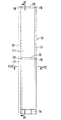
図1に示す防音壁構造(1)は、鉄道の高架(2)のはね出し部(2a)に設置されたもので、複数の防音壁構成部材(10)が鉄道用の軌道と概ね平行に連続的に配置されるとともに、複数の防音壁構成部材(10)同士が胴縁(4)によって連結されることで形成されている。各防音壁構成部材(10)は、例えば、幅が500mm、高さが3400mmとされる。各防音壁構成部材(10)は、幅が300mm〜1000mm、高さが1500〜4000mmの範囲で適宜選択される。施工に際しては、幅を同じ(例えば500mm)として、複数種類の高さ(例えば、高さ2200,2700,3100および3400mm)の品揃えとすることが好ましい。 The soundproof wall structure (1) shown in FIG. 1 is installed on the protruding part (2a) of the railway overhead (2), and a plurality of soundproof wall constituting members (10) are substantially parallel to the railroad track. The plurality of soundproof wall constituting members (10) are connected to each other by the trunk edge (4). Each sound barrier member (10) has, for example, a width of 500 mm and a height of 3400 mm. Each soundproof wall constituting member (10) is appropriately selected in a range of 300 mm to 1000 mm in width and 1500 to 4000 mm in height. At the time of construction, it is preferable that the width is the same (for example, 500 mm), and the product has a variety of heights (for example, heights of 2200, 2700, 3100, and 3400 mm).
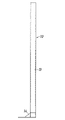
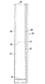
各防音壁構成部材(10)は、図2以降に詳細に示すように、防音パネルからなる壁体(11)と、左右縦材(12)(13)と、ベース部材(14)と、天面および中間の横材(15)(16)と、隙間塞ぎ材(17)とからなる。 As shown in detail in FIG. 2 and subsequent figures, each soundproof wall constituting member (10) includes a wall body (11) made of a soundproof panel, left and right vertical members (12) (13), a base member (14), a ceiling member. It consists of surface and intermediate cross members (15) and (16), and a gap plugging material (17).
各防音壁構成部材(10)において、壁体(11)、左右縦材(12)(13)、ベース部材(14)、横材(15)(16)および隙間塞ぎ材(17)は、一体化されており、このような防音壁構成部材(10)を高架(2)のはね出し部(2a)に順次固定していくことで、所望の範囲に防音壁構造(1)が設置される。 In each sound barrier component (10), the wall (11), left and right vertical members (12) (13), base member (14), cross members (15) (16) and gap plugging material (17) are integrated. The soundproof wall structure (1) is installed in a desired range by sequentially fixing such soundproof wall components (10) to the protruding portion (2a) of the elevated (2). The
壁体(11)、左右縦材(12)(13)およびベース部材(14)が防音壁構造(1)の主要構成要素であり、防音壁構成部材(10)は、少なくともこれらの部材(11)(12)(13)(14)が一体化されたものとされる。そして、この実施形態では、横材(15)(16)および隙間塞ぎ材(17)も防音壁構成部材(10)に一体に設けられている。 The wall body (11), the left and right vertical members (12) (13), and the base member (14) are the main components of the soundproof wall structure (1), and the soundproof wall component member (10) is at least these members (11 ) (12) (13) (14) are integrated. In this embodiment, the cross members (15), (16) and the gap plugging material (17) are also provided integrally with the soundproof wall constituting member (10).
壁体(11)は、防音パネルからなるものであってもよく、コンクリート板のような防音板からなるものであってもよい。 The wall body (11) may be made of a soundproof panel or may be made of a soundproof board such as a concrete board.
防音パネルからなる壁体(11)としては、種々のものが使用されるが、図11に示すように、鋼板からなる直方体状の筐体(51)内に鋼板からなる複数の反射板(52)が設けられて、反射板(52)間にグラスウール等の吸音材(53)が充填されているものが防音効果に優れている点で好ましい。 As the wall body (11) made of a soundproof panel, various types are used. As shown in FIG. 11, a plurality of reflectors (52 ), And a sound absorbing material (53) such as glass wool is filled between the reflecting plates (52) from the viewpoint of excellent soundproofing effect.
左右縦材(12)(13)は、水平断面コの字型の溝形鋼とされて、その開口同士が対向するように配されている。図6および図8に拡大して示すように、左右縦材(12)(13)の前壁(12a)(13a)と後壁(12b)(13b)との距離は、防音パネル(11)の厚み(前後方向寸法)よりも大きくなされており、左右縦材(12)(13)の前壁(12a)(13a)と後壁(12b)(13b)との間には、防音パネル(11)の左右縁部と各横材(15)(16)の左右端部とが嵌め入れられている。 The left and right vertical members (12) and (13) are formed into a U-shaped groove steel with a horizontal cross section, and are arranged so that the openings face each other. 6 and 8, the distance between the front walls (12a) and (13a) and the rear walls (12b) and (13b) of the left and right vertical members (12) and (13) depends on the soundproof panel (11). The sound insulation panel (between the front wall (12a) (13a) and the rear wall (12b) (13b) of the left and right vertical members (12) (13) The left and right edge portions of 11) and the left and right end portions of the cross members (15) and (16) are fitted.
図9に示すように、各横材(15)(16)は、断面略コの字型のリップ付き溝形鋼とされている。 As shown in FIG. 9, each of the cross members (15) and (16) is a grooved steel with a lip having a substantially U-shaped cross section.
ベース部材(14)は、図12および図13にその単品の形状を示すように、鋼板を組み合わせて形成されたもので、底板(21)と、底板(21)の後端に連なる後板(22)と、後板(22)の上端部に連なる頂板(23)と、底板(21)の左右の中間部と頂板(23)の左右の中間部との間に渡された左右の側板(24)(25)とからなる。 The base member (14) is formed by combining steel plates as shown in FIGS. 12 and 13 in the shape of a single product. The base plate (21) and a rear plate (21) connected to the rear end of the bottom plate (21) ( 22), a top plate (23) connected to the upper end portion of the rear plate (22), and left and right side plates passed between the left and right intermediate portions of the bottom plate (21) and the left and right intermediate portions of the top plate (23) ( 24) (25).
頂板(23)は、左右に長い略長方形状とされ、頂板(23)の前後長さは、左右縦材(12)(13)の前後長さとほぼ同じとされている。底板(21)は、略正方形状とされ、底板(21)の前後長さは、頂板(23)の前後長さよりも大きくなされ、底板(21)は、頂板(23)に対して前方に張り出している。 The top plate (23) has a substantially rectangular shape that is long to the left and right, and the front and rear lengths of the top plate (23) are substantially the same as the front and rear lengths of the left and right vertical members (12) and (13). The bottom plate (21) has a substantially square shape, and the front and rear length of the bottom plate (21) is larger than the front and rear length of the top plate (23), and the bottom plate (21) projects forward with respect to the top plate (23). ing.
後板(22)は、左右に長い略長方形状とされ、後板(22)の左右長さは、底板(21)の左右長さよりも、左右縦材(12)(13)の左右の長さ分だけ短くなされている。底板(21)の後縁部に後板(22)の下縁部が溶接され、後板(22)の上縁部に頂板(23)の後縁部が溶接されている。 The rear plate (22) has a substantially rectangular shape that is long to the left and right, and the left and right length of the rear plate (22) is longer than the left and right lengths of the bottom plate (21). It has been made shorter. The lower edge of the rear plate (22) is welded to the rear edge of the bottom plate (21), and the rear edge of the top plate (23) is welded to the upper edge of the rear plate (22).
各側板(24)(25)は、側面から見て台形状をなし、その上面が頂板(23)の下面に溶接され、その下面が底板(21)の上面に溶接され、その後面が後板(22)の前面に溶接されている。 Each side plate (24) (25) has a trapezoidal shape when viewed from the side, its upper surface is welded to the lower surface of the top plate (23), its lower surface is welded to the upper surface of the bottom plate (21), and its rear surface is the rear plate It is welded to the front of (22).
左側の縦材(12)の下端面は、底板(21)の左後の角部によって受け止められて底板(21)に溶接されている。右側の縦材(13)の下端面は、底板(21)の右後の角部によって受け止められて底板(21)に溶接されている。頂板(23)の左右端部は、左右縦材(12)(13)の開口部内にちょうど入り込む形状とされて、図8から分かるように、左右縦材(12)(13)の後壁(12b)(13b)の後面と後板(22)の後面とが面一に、左右縦材(12)(13)の前壁(12a)(13a)の前面と頂板(23)の前面とが面一になされている。 The lower end surface of the left longitudinal member (12) is received by the left rear corner of the bottom plate (21) and welded to the bottom plate (21). The lower end surface of the right vertical member (13) is received by the right rear corner of the bottom plate (21) and welded to the bottom plate (21). The left and right end portions of the top plate (23) are shaped so as to enter the openings of the left and right vertical members (12) and (13), and as can be seen from FIG. 8, the rear walls of the left and right vertical members (12) and (13) ( 12b) (13b) and the rear surface of the rear plate (22) are flush with each other, and the front surfaces of the front walls (12a) (13a) of the left and right vertical members (12) (13) and the front surface of the top plate (23) It has been made flush.
底板(21)には、複数のアンカーボルト挿通用の孔(26)が設けられており、底板(21)をアンカーボルト(図示略)ではね出し部(2a)に固定することで、ベース部材(14)したがって防音壁構成部材(10)を高架(2)に固定することができる。 The base plate (21) is provided with a plurality of holes (26) for inserting anchor bolts, and the base plate (21) is fixed to the protruding portion (2a) with an anchor bolt (not shown), thereby providing a base member. (14) Therefore, the soundproof wall constituting member (10) can be fixed to the elevated (2).
隙間塞ぎ材(17)は、左右縦材(12)(13)と上下方向の長さがほぼ同じ鋼板とされて、左右縦材(12)(13)のいずれか一方(この実施形態では左側の縦材(12))に固定されている。隙間塞ぎ材(17)の幅(左右方向の寸法)は、左右縦材(12)(13)の幅(左右方向の寸法)の2倍とされている。これにより、隙間塞ぎ材(17)は、左側の縦材(12)よりも左方向(外側)に張り出した状態で、左側の縦材(12)に固定されている。 The gap plugging material (17) is a steel plate having substantially the same length in the vertical direction as the left and right vertical members (12) and (13), and one of the left and right vertical members (12) and (13) (in this embodiment, the left side) (12)). The width (dimension in the left-right direction) of the gap plugging material (17) is twice the width (dimension in the left-right direction) of the left and right vertical members (12) and (13). As a result, the gap plugging material (17) is fixed to the left vertical member (12) in a state of projecting leftward (outside) from the left vertical member (12).
壁体(11)の左右縦材(12)(13)への固定は、図5に示すように、背面からのリベット(18)による固定によって行われている。 The wall body (11) is fixed to the left and right vertical members (12) and (13) by fixing with a rivet (18) from the back as shown in FIG.
図10に拡大して示すように、天面の横材(15)の左端部と左側の縦材(12)の上端部と隙間塞ぎ材(17)の上端部とは、リベット(18)によって一体とされている。 As shown in FIG. 10 in an enlarged manner, the top end of the cross member (15) on the top surface, the upper end portion of the left vertical member (12), and the upper end portion of the gap closing member (17) are separated by rivets (18). It is united.
拡大図は省略するが、図2、図3などに示すように、中間の横材(16)の左端部と左側の縦材(12)の中間部と隙間塞ぎ材(17)の中間部とも、リベット(18)によって一体とされている。 Although the enlarged view is omitted, as shown in FIGS. 2 and 3, the left end of the intermediate cross member (16), the intermediate portion of the left vertical member (12), and the intermediate portion of the gap plugging material (17) It is united by a rivet (18).
同様に、天面の横材(15)の右端部と右側の縦材(13)の上端部とがリベット(18)によって一体とされており、中間の横材(16)の右端部と右側の縦材(13)の中間部とも、リベットによって一体とされている。 Similarly, the right end of the top cross member (15) and the upper end of the right vertical member (13) are integrated by a rivet (18), and the right end and right side of the intermediate cross member (16) are integrated. The intermediate part of the vertical member (13) is also integrated by rivets.
上記の防音壁構造(10)を使用して防音壁構造(1)を設置するには、まず、ベース部材(14)を製作しておいてから、壁体(11)、左右縦材(12)(13)、ベース部材(14)、横材(15)(16)および隙間塞ぎ材(17)をリベット(18)および溶接によって一体化することで、防音壁構成部材(10)を必要な数だけ製作する。防音壁構成部材(10)の製作は、防音壁構造(1)の設置箇所で行ってもよいし、一部または全部を工場において製作するようにしてもよい。次いで、防音壁構成部材(10)を構造物(例えば高架(2)のはね出し部(2a))に順次配置して、防音壁構成部材(10)のベース部材(14)を構造物にアンカー固定などで固定する。次いで、従来から行われているように、胴縁(4)などによって、複数の防音壁構成部材(10)同士を連結固定する。 In order to install the soundproof wall structure (1) using the above soundproof wall structure (10), first the base member (14) is manufactured, and then the wall body (11), the left and right vertical members (12 ) (13), base member (14), cross member (15) (16) and gap plugging member (17) are integrated by rivet (18) and welding, so that soundproof wall constituting member (10) is required. Make as many as you want. The soundproof wall constituting member (10) may be manufactured at the place where the soundproof wall structure (1) is installed, or a part or all of it may be manufactured in a factory. Next, the sound barrier constituent member (10) is sequentially arranged on the structure (for example, the protruding portion (2a) of the elevated (2)), and the base member (14) of the sound barrier constituent member (10) is made into the structure. Fix with anchors. Next, as conventionally performed, the plurality of soundproof wall constituting members (10) are connected and fixed by the trunk edge (4) or the like.
胴縁(4)を使用した連結固定は、耐久性の点からは、省略することもできるが、胴縁(4)を使用して複数の防音壁構成部材(10)同士を連結固定しておくことによって、風圧等が作用した際に、隣接する防音壁構成部材(10)同士のばたつきを抑えることができる。 Connection and fixing using the trunk edge (4) can be omitted from the viewpoint of durability, but the plurality of sound barrier components (10) can be connected and fixed together using the trunk edge (4). Thus, when the wind pressure or the like acts, fluttering between adjacent soundproof wall constituting members (10) can be suppressed.
上記設置作業において、防音壁構造(1)を設置するための基本的な作業は、ベース部材(14)をアンカーボルト等で構造物に固定していくだけでよいので、支柱を設置して、これに防音パネルを取り付けて行く従来の設置作業に比べて、大幅に簡素化することができる。 In the above installation work, the basic work for installing the soundproof wall structure (1) is only to fix the base member (14) to the structure with anchor bolts, etc. Compared with the conventional installation work in which a soundproof panel is attached to the door, it can be greatly simplified.
上記防音壁構成部材(10)によると、防音パネルからなる壁体(11)に作用する風荷重を支柱だけで受けていた従来の防音壁に対し、左右縦材(12)(13)およびこれに一体化されたベース部材(14)で分担することになり、左右縦材(12)(13)の下端部およびベース部材(14)に作用する応力を低減することができる。そして、防音壁構造(1)の設置区間が高架区間の場合には、高架(2)のはね出し部(2a)に分散して伝達されることになり、左右縦材(12)(13)およびベース部材(14)の負担が軽減され、寿命を長くすることができるとともに、左右縦材(12)(13)を太いものにする必要がないので、軽量化もできる。したがって、高架(2)のはね出し部(2a)を分厚いものにする必要もない。 According to the sound barrier component member (10), the left and right vertical members (12) and (13) and this are compared to the conventional sound barrier that received the wind load acting on the wall body (11) made of the soundproof panel only with the support. The base member (14) integrated with the base member (14) can be shared, and the stress acting on the lower ends of the left and right vertical members (12) (13) and the base member (14) can be reduced. And when the installation section of the soundproof wall structure (1) is an elevated section, it will be distributed and transmitted to the protruding part (2a) of the elevated (2), and the left and right vertical members (12) (13 ) And the base member (14) can be reduced, the life can be extended, and the left and right vertical members (12) and (13) do not need to be thickened, so that the weight can be reduced. Therefore, it is not necessary to make the protruding portion (2a) of the elevated (2) thick.
図示省略するが、各防音壁構成部材(10)は、盛土に固定されるようにしてももちろんよい。 Although not shown in the drawings, the sound barrier constituent members (10) may of course be fixed to the embankment.
また、上記実施形態において、防音パネルからなる壁体(11)、左右縦材(12)(13)、ベース部材(14)、横材(15)(16)および隙間塞ぎ材(17)は、それぞれが別の部材とされて、リベット止めおよび溶接により互いに固定されているが、防音壁構成部材(10)の構成は、これに限定されるものではない。 Further, in the above embodiment, the wall body (11) made of the soundproof panel, the left and right vertical members (12) (13), the base member (14), the horizontal members (15) (16) and the gap plugging material (17) are: Each is a separate member and fixed to each other by riveting and welding, but the configuration of the soundproof wall constituting member (10) is not limited to this.
例えば、壁体(11)を構成している筐体(51)を形成する際に、鋼板に対して折曲げ加工等の適宜な加工を行って左右縦材(12)(13)を一体に形成するようにしてもよい。また、左右縦材(12)(13)とベース部材(14)とを一体に形成するようにしてもよい。左右縦材(12)(13)は、水平断面コの字型に限られるものではなく、例えば水平断面L字型であってもよい。横材(15)(16)は省略することもできる。隙間塞ぎ材(17)は、防音壁構成部材(10)に予め固定しておかなくてもよい。 For example, when forming the casing (51) constituting the wall (11), the right and left vertical members (12) (13) are integrated by performing appropriate processing such as bending on the steel plate. You may make it form. Further, the left and right vertical members (12) (13) and the base member (14) may be integrally formed. The left and right vertical members (12) and (13) are not limited to a U-shaped horizontal section, and may be an L-shaped horizontal section, for example. The cross members (15) and (16) can be omitted. The gap plugging material (17) may not be fixed in advance to the soundproof wall constituting member (10).
(1) 防音壁構造
(2) 高架
(2a) はね出し部
(4) 胴縁
(10) 防音壁構成部材
(11) 壁体
(12)(13) 左右縦材
(14) ベース部材
(15)(16) 横材
(17) 隙間塞ぎ材
(1) Soundproof wall structure
(2) Elevated
(2a) Splashing part
(4) Torso edge
(10) Sound barrier components
(11) Wall body
(12) (13) Left and right vertical members
(14) Base member
(15) (16) Crosspiece
(17) Gap closing material
Claims (13)
Priority Applications (1)
| Application Number | Priority Date | Filing Date | Title |
|---|---|---|---|
| JP2013138855A JP6220579B2 (en) | 2013-07-02 | 2013-07-02 | Soundproof wall constituent member, soundproof wall structure, and method of assembling soundproof wall structure |
Applications Claiming Priority (1)
| Application Number | Priority Date | Filing Date | Title |
|---|---|---|---|
| JP2013138855A JP6220579B2 (en) | 2013-07-02 | 2013-07-02 | Soundproof wall constituent member, soundproof wall structure, and method of assembling soundproof wall structure |
Publications (2)
| Publication Number | Publication Date |
|---|---|
| JP2015010452A true JP2015010452A (en) | 2015-01-19 |
| JP6220579B2 JP6220579B2 (en) | 2017-10-25 |
Family
ID=52303851
Family Applications (1)
| Application Number | Title | Priority Date | Filing Date |
|---|---|---|---|
| JP2013138855A Active JP6220579B2 (en) | 2013-07-02 | 2013-07-02 | Soundproof wall constituent member, soundproof wall structure, and method of assembling soundproof wall structure |
Country Status (1)
| Country | Link |
|---|---|
| JP (1) | JP6220579B2 (en) |
Cited By (4)
| Publication number | Priority date | Publication date | Assignee | Title |
|---|---|---|---|---|
| CN106592454A (en) * | 2016-12-27 | 2017-04-26 | 中国铁道科学研究院节能环保劳卫研究所 | Offset steel stand column for railway sound barrier |
| JP2019007193A (en) * | 2017-06-22 | 2019-01-17 | 東海旅客鉄道株式会社 | Sound-proof wall component and sound-proof wall structure |
| JP2019056268A (en) * | 2017-09-22 | 2019-04-11 | 日鐵住金建材株式会社 | Sound insulation panel unit, construction method for sound insulation panel unit, and repair method for sound insulation wall |
| JP2019085754A (en) * | 2017-11-06 | 2019-06-06 | 日鐵住金建材株式会社 | Sound insulation wall unit |
Citations (11)
| Publication number | Priority date | Publication date | Assignee | Title |
|---|---|---|---|---|
| JPS6266910U (en) * | 1985-10-11 | 1987-04-25 | ||
| JP3031028U (en) * | 1996-05-09 | 1996-11-12 | 小沢コンクリート工業株式会社 | Soundproofing equipment with concrete panels |
| JPH08333725A (en) * | 1995-06-08 | 1996-12-17 | Sanken Steel:Kk | Sound insulating panel and sound insulating wall device therewith, and assembling method thereof |
| JPH0931925A (en) * | 1995-07-24 | 1997-02-04 | Sumitomo Chem Co Ltd | Transparent noise barrier |
| JPH09264007A (en) * | 1996-03-29 | 1997-10-07 | Bridgestone Corp | Sound insulating wall |
| JPH1037136A (en) * | 1996-07-18 | 1998-02-10 | Toyo Bouon Kensetsu Kk | Sound insulation wall |
| JP2002317408A (en) * | 2001-04-19 | 2002-10-31 | Ngk Insulators Ltd | Translucent sound insulation board and sound insulation wall |
| JP2003328326A (en) * | 2002-05-14 | 2003-11-19 | Unipres Corp | Sound insulating apparatus |
| US20040128947A1 (en) * | 2001-05-17 | 2004-07-08 | Toshihiro Ito | Sound-proof wall made of frp, and method of producing the same |
| JP2012180688A (en) * | 2011-03-02 | 2012-09-20 | Sekisui Chem Co Ltd | Soundproof panel |
| JP2013068018A (en) * | 2011-09-22 | 2013-04-18 | West Japan Railway Co | Wall structure |
-
2013
- 2013-07-02 JP JP2013138855A patent/JP6220579B2/en active Active
Patent Citations (11)
| Publication number | Priority date | Publication date | Assignee | Title |
|---|---|---|---|---|
| JPS6266910U (en) * | 1985-10-11 | 1987-04-25 | ||
| JPH08333725A (en) * | 1995-06-08 | 1996-12-17 | Sanken Steel:Kk | Sound insulating panel and sound insulating wall device therewith, and assembling method thereof |
| JPH0931925A (en) * | 1995-07-24 | 1997-02-04 | Sumitomo Chem Co Ltd | Transparent noise barrier |
| JPH09264007A (en) * | 1996-03-29 | 1997-10-07 | Bridgestone Corp | Sound insulating wall |
| JP3031028U (en) * | 1996-05-09 | 1996-11-12 | 小沢コンクリート工業株式会社 | Soundproofing equipment with concrete panels |
| JPH1037136A (en) * | 1996-07-18 | 1998-02-10 | Toyo Bouon Kensetsu Kk | Sound insulation wall |
| JP2002317408A (en) * | 2001-04-19 | 2002-10-31 | Ngk Insulators Ltd | Translucent sound insulation board and sound insulation wall |
| US20040128947A1 (en) * | 2001-05-17 | 2004-07-08 | Toshihiro Ito | Sound-proof wall made of frp, and method of producing the same |
| JP2003328326A (en) * | 2002-05-14 | 2003-11-19 | Unipres Corp | Sound insulating apparatus |
| JP2012180688A (en) * | 2011-03-02 | 2012-09-20 | Sekisui Chem Co Ltd | Soundproof panel |
| JP2013068018A (en) * | 2011-09-22 | 2013-04-18 | West Japan Railway Co | Wall structure |
Cited By (7)
| Publication number | Priority date | Publication date | Assignee | Title |
|---|---|---|---|---|
| CN106592454A (en) * | 2016-12-27 | 2017-04-26 | 中国铁道科学研究院节能环保劳卫研究所 | Offset steel stand column for railway sound barrier |
| CN106592454B (en) * | 2016-12-27 | 2022-09-20 | 中国铁道科学研究院节能环保劳卫研究所 | Railway sound barrier offset steel upright post |
| JP2019007193A (en) * | 2017-06-22 | 2019-01-17 | 東海旅客鉄道株式会社 | Sound-proof wall component and sound-proof wall structure |
| JP7041422B2 (en) | 2017-06-22 | 2022-03-24 | 東海旅客鉄道株式会社 | Soundproof wall components and soundproof wall structure |
| JP7041422B6 (en) | 2017-06-22 | 2022-04-07 | 東海旅客鉄道株式会社 | Soundproof wall components and soundproof wall structure |
| JP2019056268A (en) * | 2017-09-22 | 2019-04-11 | 日鐵住金建材株式会社 | Sound insulation panel unit, construction method for sound insulation panel unit, and repair method for sound insulation wall |
| JP2019085754A (en) * | 2017-11-06 | 2019-06-06 | 日鐵住金建材株式会社 | Sound insulation wall unit |
Also Published As
| Publication number | Publication date |
|---|---|
| JP6220579B2 (en) | 2017-10-25 |
Similar Documents
| Publication | Publication Date | Title |
|---|---|---|
| JP6220579B2 (en) | Soundproof wall constituent member, soundproof wall structure, and method of assembling soundproof wall structure | |
| KR101108127B1 (en) | Soundproof wall of soundproof panel easy repairs | |
| JP6095925B2 (en) | Load bearing wall frame | |
| JP6053485B2 (en) | Installation structure of studs in existing building | |
| KR101329420B1 (en) | Energy dissipation system of vertical slit shear wall | |
| KR20100115528A (en) | Pre-casting protective wall and railway bridge using the same | |
| JP2014051792A (en) | Roof structure | |
| JP2013231305A (en) | Inspection path for bridge | |
| JP2016017323A (en) | Seismic control structure | |
| JP5371390B2 (en) | Building unit reinforcement structure and unit building | |
| RU2430222C1 (en) | Bracket of suspended facade system with air clearance (versions) | |
| KR20180091582A (en) | Composite through bridge and the construction method thereof | |
| JP7235192B2 (en) | Support structure for ceiling panel and unit building | |
| JP5892781B2 (en) | Curtain wall type outer wall structure | |
| JP5892782B2 (en) | Curtain wall type outer wall structure | |
| JP6917865B2 (en) | Soundproof wall unit | |
| KR101715787B1 (en) | A soundproof wall for easy maintenance | |
| KR20040032374A (en) | A soundproofing plate connecting structure for soundproofed wall | |
| JP4331055B2 (en) | Vibration sound absorption structure of elevated road | |
| JP6507053B2 (en) | Exterior wall structure of the building | |
| JP2019007193A (en) | Sound-proof wall component and sound-proof wall structure | |
| JP7457554B2 (en) | Floor structure of a wooden building | |
| KR101354597B1 (en) | Sound absorption wall for high-speed rail tunnel | |
| JP2019148134A (en) | Sound absorption structure | |
| JP7457548B2 (en) | Floor structure of wooden buildings |
Legal Events
| Date | Code | Title | Description |
|---|---|---|---|
| A621 | Written request for application examination |
Free format text: JAPANESE INTERMEDIATE CODE: A621 Effective date: 20160610 |
|
| A131 | Notification of reasons for refusal |
Free format text: JAPANESE INTERMEDIATE CODE: A131 Effective date: 20170425 |
|
| A977 | Report on retrieval |
Free format text: JAPANESE INTERMEDIATE CODE: A971007 Effective date: 20170426 |
|
| A521 | Request for written amendment filed |
Free format text: JAPANESE INTERMEDIATE CODE: A523 Effective date: 20170623 |
|
| TRDD | Decision of grant or rejection written | ||
| A01 | Written decision to grant a patent or to grant a registration (utility model) |
Free format text: JAPANESE INTERMEDIATE CODE: A01 Effective date: 20170905 |
|
| A61 | First payment of annual fees (during grant procedure) |
Free format text: JAPANESE INTERMEDIATE CODE: A61 Effective date: 20171002 |
|
| R150 | Certificate of patent or registration of utility model |
Ref document number: 6220579 Country of ref document: JP Free format text: JAPANESE INTERMEDIATE CODE: R150 |
|
| R250 | Receipt of annual fees |
Free format text: JAPANESE INTERMEDIATE CODE: R250 |
|
| R250 | Receipt of annual fees |
Free format text: JAPANESE INTERMEDIATE CODE: R250 |
|
| R250 | Receipt of annual fees |
Free format text: JAPANESE INTERMEDIATE CODE: R250 |