JP2015001663A - Image processing apparatus, terminal device, image processing system, image processing method, and image processing program - Google Patents

Image processing apparatus, terminal device, image processing system, image processing method, and image processing program Download PDF

Info

Publication number
JP2015001663A
JP2015001663A JP2013126851A JP2013126851A JP2015001663A JP 2015001663 A JP2015001663 A JP 2015001663A JP 2013126851 A JP2013126851 A JP 2013126851A JP 2013126851 A JP2013126851 A JP 2013126851A JP 2015001663 A JP2015001663 A JP 2015001663A
Authority
JP
Japan
Prior art keywords
area
image
region
unit
attention
Prior art date
Legal status (The legal status is an assumption and is not a legal conclusion. Google has not performed a legal analysis and makes no representation as to the accuracy of the status listed.)
Pending
Application number
JP2013126851A
Other languages
Japanese (ja)
Inventor
松 美 佳 峰
Mika Minematsu
松 美 佳 峰
会 津 宏 幸
Hiroyuki Aizu
津 宏 幸 会
瀬 恒太郎 伊
Tsunetaro Ise
瀬 恒太郎 伊
Current Assignee (The listed assignees may be inaccurate. Google has not performed a legal analysis and makes no representation or warranty as to the accuracy of the list.)
Toshiba Corp
Original Assignee
Toshiba Corp
Priority date (The priority date is an assumption and is not a legal conclusion. Google has not performed a legal analysis and makes no representation as to the accuracy of the date listed.)
Filing date
Publication date
Application filed by Toshiba Corp filed Critical Toshiba Corp
Priority to JP2013126851A priority Critical patent/JP2015001663A/en
Publication of JP2015001663A publication Critical patent/JP2015001663A/en
Pending legal-status Critical Current

Links

Images

Landscapes

  • Processing Or Creating Images (AREA)
  • Digital Computer Display Output (AREA)
  • Controls And Circuits For Display Device (AREA)
  • User Interface Of Digital Computer (AREA)

Abstract

【課題】注目すべき事象が発生した場合に、その状況を把握できる可能性を向上させる。【解決手段】画像処理装置1の注目点検出部132は、画像において予め決められた事象が発生した領域である第1の領域を検出する。画像処理装置1の注目領域検出部133は、その注目点検出部132が検出した第1の領域の情報に基づいて第2の領域を上記画像内から検出する。画像処理装置1の注目領域表示部134は、注目領域検出部133が検出した第2の領域の情報に基づいて、画像に対する出力処理を行う。【選択図】図1An object of the present invention is to improve the possibility of grasping the situation when a remarkable event occurs. An attention point detection unit 132 of an image processing apparatus 1 detects a first region that is a region where a predetermined event has occurred in an image. The attention area detection unit 133 of the image processing apparatus 1 detects the second area from the image based on the information of the first area detected by the attention point detection unit 132. The attention area display unit 134 of the image processing apparatus 1 performs output processing on the image based on the information on the second area detected by the attention area detection unit 133. [Selection] Figure 1

Description

本発明の実施形態は、画像処理装置、端末装置、画像処理システム、画像処理方法及び画像処理プログラムに関する。   Embodiments described herein relate generally to an image processing device, a terminal device, an image processing system, an image processing method, and an image processing program.

複数の監視対象機器の監視画面を中央監視室の表示装置上で集中的に監視する遠隔監視システムが存在する。遠隔監視システムでは、監視対象機器に問題が発生した場合に、即座に状況を把握して対応することが重要である。   There is a remote monitoring system that centrally monitors a plurality of monitoring target devices on a display device in a central monitoring room. In a remote monitoring system, when a problem occurs in a monitoring target device, it is important to immediately grasp the situation and take action.

特開平8−263253号公報JP-A-8-263253

しかしながら、遠隔監視システムは、監視者または現場の作業員が注目すべき事象(例えば、監視対象機器に問題)が発生した場合に、その事象に関する情報が適切に表示されないために、監視者または現場の作業員がその状況を把握しにくかったり、把握できなかったりする場合があった。   However, when an event that should be noticed by a supervisor or a field worker (for example, a problem in a monitored device) occurs, the remote monitoring system does not properly display information about the event. There were cases in which it was difficult or impossible to grasp the situation.

そこで本発明の一態様は、上記問題に鑑みてなされたものであり、注目すべき事象が発生した場合に、その状況を把握できる可能性を向上させる画像処理装置、端末装置、画像処理システム、画像処理方法及び画像処理プログラムを提供することを課題とする。   Therefore, one aspect of the present invention has been made in view of the above problems, and an image processing device, a terminal device, an image processing system, and an image processing device that improve the possibility of grasping the situation when an event to be noticed occurs. It is an object to provide an image processing method and an image processing program.

本発明の実施形態によれば、画像処理装置の第一領域検出部は、画像において予め決められた事象が発生した領域である第1の領域を検出する。画像処理装置の第二領域検出部は、その第一領域検出部が検出した第1の領域の情報に基づいて第2の領域を上記画像内から検出する。画像処理装置の出力処理部は、第二領域検出部が検出した第2の領域の情報に基づいて、画像に対する出力処理を行う。   According to the embodiment of the present invention, the first region detection unit of the image processing apparatus detects a first region that is a region where a predetermined event has occurred in an image. The second area detection unit of the image processing apparatus detects the second area from the image based on the information on the first area detected by the first area detection unit. The output processing unit of the image processing apparatus performs an output process on the image based on the information on the second area detected by the second area detecting unit.

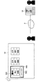
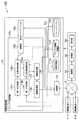
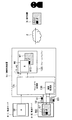
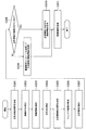
第1の実施形態に係る画像処理装置の構成を示す概略ブロック図である。1 is a schematic block diagram illustrating a configuration of an image processing apparatus according to a first embodiment. 第1の実施形態に係る注目点および注目領域の第1の例を示す図である。It is a figure which shows the 1st example of the attention point and attention area which concern on 1st Embodiment. 第1の実施形態に係る注目点および注目領域の第2の例を示す図である。It is a figure which shows the 2nd example of the attention point and attention area which concern on 1st Embodiment. 第1の実施形態に係る注目点および注目領域の第3の例を示す図である。It is a figure which shows the 3rd example of the attention point and attention area which concern on 1st Embodiment. 第1の実施形態に係る画像処理装置の処理の流れの一例を示すフローチャートである。3 is a flowchart illustrating an example of a processing flow of the image processing apparatus according to the first embodiment. 2の実施形態に係る画像処理システムの構成を示す概略ブロック図である。It is a schematic block diagram which shows the structure of the image processing system which concerns on 2 embodiment. 第2の実施形態における注目点および注目領域の例を示す図である。It is a figure which shows the example of the attention point and attention area in 2nd Embodiment. 第2の実施形態に係る画像処理装置の処理の流れの一例を示すフローチャートである。10 is a flowchart illustrating an example of a processing flow of an image processing apparatus according to a second embodiment. 第3の実施形態に係る画像処理システムの構成を示す概略ブロック図である。It is a schematic block diagram which shows the structure of the image processing system which concerns on 3rd Embodiment. 第3の実施形態における注目点と注目領域の例を示す図である。It is a figure which shows the example of the attention point and attention area in 3rd Embodiment. 第3の実施形態に係る画像処理装置の処理の流れの一例を示すフローチャートである。10 is a flowchart illustrating an example of a processing flow of an image processing apparatus according to a third embodiment.

以下、本発明の実施形態について、図面を参照して詳細に説明する。各実施形態において、画像処理装置が画像内から事象が発生した領域として検出する第1の領域を注目点とし、画像処理装置がその画像内から検出する第2の領域を遠隔監視システムの監視者または現場の作業員に注目してもらいたい注目領域として説明する。   Hereinafter, embodiments of the present invention will be described in detail with reference to the drawings. In each embodiment, the first area detected by the image processing apparatus as an area where an event has occurred from within the image is set as a point of interest, and the second area detected by the image processing apparatus from within the image is the monitor of the remote monitoring system. Or, it will be explained as a region of interest that the workers on the site want to pay attention to.

(第1の実施形態)
図1は、第1の実施形態に係る画像処理装置1の構成を示す概略ブロック図である。画像処理装置1は、記憶部11、アプリケーション実行部12及びウィンドウ処理部13を備える。
(First embodiment)
FIG. 1 is a schematic block diagram showing the configuration of the image processing apparatus 1 according to the first embodiment. The image processing apparatus 1 includes a storage unit 11, an application execution unit 12, and a window processing unit 13.

記憶部11には、アプリケーション実行部12が実行するアプリケーションが記憶されている。そのアプリケーションは、画像処理装置1上で動作する各種処理を提供するプログラムである。ここで記憶部11は、規則記憶部111及びフレームバッファ112を備える。
規則記憶部111は、画像内においてどのような事象が起こった領域を注目点(第1の領域)として検出するかが定められた規則(以下、注目点検出規則ともいう)が記憶されている。
フレームバッファ112は、画像処理装置1が生成する画像情報を保持する。なお、フレームバッファは、RAM(Random Access Memory)、HDD(Hard Disk Drive)、光ディスク、メモリカードなどの一般的に利用されているあらゆる記憶媒体により構成することができる。
The storage unit 11 stores an application executed by the application execution unit 12. The application is a program that provides various processes that operate on the image processing apparatus 1. Here, the storage unit 11 includes a rule storage unit 111 and a frame buffer 112.
The rule storage unit 111 stores a rule (hereinafter, also referred to as an attention point detection rule) in which an area in which an event has occurred in an image is determined as an attention point (first area). .
The frame buffer 112 holds image information generated by the image processing apparatus 1. Note that the frame buffer can be configured by any commonly used storage medium such as a RAM (Random Access Memory), an HDD (Hard Disk Drive), an optical disk, and a memory card.

アプリケーション実行部12は、記憶部11に記憶されたアプリケーションを読み出し、読み出したアプリケーションを実行する。本実施形態に係るアプリケーション実行部12は一例として、ウィンドウ処理部13の後述する注目点検出部132に、注目点の画像内における位置及び範囲を示す注目点情報を通知する。ここで、後述する図2の領域R11に示すように、注目点が四角い画像領域の場合、注目点情報は例えば、その四角い画像領域の左上の座標とその四角い画像領域の高さ及び幅との組、またはその四角い画像領域の四隅の座標である。
なお、本実施形態では一例として、注目点情報は、注目点の画像内における位置及び範囲を示すが、これに限らず、注目点が一画像の場合、注目点情報は注目点の画像内における位置だけを示してもよい。このことから、注目点情報は少なくとも注目点の画像内における位置を含む。
The application execution unit 12 reads an application stored in the storage unit 11 and executes the read application. As an example, the application execution unit 12 according to the present embodiment notifies the attention point detection unit 132 (to be described later) of the window processing unit 13 of attention point information indicating the position and range of the attention point in the image. Here, as shown in a region R11 of FIG. 2 to be described later, when the attention point is a square image region, the attention point information includes, for example, the upper left coordinates of the square image region and the height and width of the square image region. The coordinates of the four corners of a pair or its square image area.
In this embodiment, as an example, the attention point information indicates the position and range of the attention point in the image. However, the present invention is not limited to this, and when the attention point is one image, the attention point information is included in the attention point image. Only the position may be indicated. Therefore, the attention point information includes at least the position of the attention point in the image.

ウィンドウ処理部13は、アプリケーションから通知された注目点情報(ここでは、注目点の位置及び範囲)を用いて、注目領域を検出し、検出した注目領域の位置及び範囲を表す情報を表示装置5に表示させる。ここでウィンドウ処理部13は、第一の決定部131、注目点検出部(第一領域検出部)132、注目領域検出部(第二領域検出部)133及び注目領域表示部(出力処理部)134を備える。
第一の決定部131は、規則記憶部111から使用する注目点検出規則を読み出し、読み出した注目点検出規則を注目点検出部132へ出力する。ここで、注目点検出規則は一例としてアプリケーション実行部12からの注目点情報の通知を予め決められた事象として、当該注目点情報により特定される領域を注目点として検出するという規則である。
The window processing unit 13 detects the attention area using the attention point information notified from the application (here, the position and range of the attention point), and displays information indicating the position and range of the detected attention area on the display device 5. To display. Here, the window processing unit 13 includes a first determination unit 131, an attention point detection unit (first region detection unit) 132, an attention region detection unit (second region detection unit) 133, and an attention region display unit (output processing unit). 134.
The first determination unit 131 reads the attention point detection rule to be used from the rule storage unit 111 and outputs the read attention point detection rule to the attention point detection unit 132. Here, the attention point detection rule is a rule that, as an example, notification of attention point information from the application execution unit 12 is detected as a predetermined event, and a region specified by the attention point information is detected as the attention point.

なお、本実施形態では一例として、注目点検出規則は、アプリケーション実行部12から通知された注目点情報により特定される領域を注目点として検出するという規則としたが、これに限ったものではない。注目点検出部132は、ユーザまたはアプリケーションによる領域の指定を予め決められた事象として当該指定された画像領域を注目点として検出するという規則、特定の画面変化を予め決められた事象として当該画面変化が発生した画像領域を注目点として検出するという規則、またはユーザによる画像領域の操作を予め決められた事象として当該ユーザが操作した画像領域を注目点として検出するという規則、のいずれかとしてもよい。   In this embodiment, as an example, the attention point detection rule is a rule of detecting an area specified by attention point information notified from the application execution unit 12 as an attention point, but is not limited thereto. . The point-of-interest detection unit 132 detects the designated image region as a point of interest as a predetermined event when the user or application designates the region, and changes the screen as a predetermined event. Either a rule that detects an image area in which an image has occurred as a point of interest, or a rule that detects an image area operated by the user as a point of interest as a predetermined event. .

また、第一の決定部131は、アプリケーション実行部12が実行するアプリケーションの種類に応じて、注目点検出規則を決定してもよい。その場合、規則記憶部111に、アプリケーションの種類毎に注目点検出規則が記憶されていてもよく、第一の決定部131は、アプリケーション実行部12が実行するアプリケーションの種類に対応する注目点検出規則を規則記憶部111から読み出し、読み出した注目点検出規則を注目点検出部132へ出力してもよい。   In addition, the first determination unit 131 may determine the attention point detection rule according to the type of application executed by the application execution unit 12. In that case, the rule storage unit 111 may store a point-of-interest detection rule for each application type, and the first determination unit 131 detects a point of interest corresponding to the type of application executed by the application execution unit 12. The rule may be read from the rule storage unit 111 and the read attention point detection rule may be output to the attention point detection unit 132.

注目点検出部132は、第1の決定部131から入力された注目点検出規則に基づいて、画像において予め決められた事象が発生した領域である注目点を検出する。本実施形態では一例として、その注目点検出規則がアプリケーション実行部12から通知された注目点情報により特定される領域を注目点として検出するという規則であるので、注目点検出部132は一例として、アプリケーション実行部12から入力された注目点情報により特定される領域を注目点として検出する。ここで、後述する図2の領域R11に示すように、注目点が例えば四角い画像領域の場合、注目点情報は例えばその四角い画像領域の左上の座標とその四角い画像領域の高さ及び幅との組である。よって、その場合注目点検出部132は、その四角い画像領域の左上の座標とその四角い画像領域の高さ及び幅との組から四角い画像領域を注目点として検出する。注目点検出部132は、検出した注目点の位置及び範囲を示す注目点情報を注目領域検出部133へ出力する。   The attention point detection unit 132 detects an attention point that is an area where a predetermined event has occurred in the image, based on the attention point detection rule input from the first determination unit 131. In the present embodiment, as an example, the attention point detection rule is a rule of detecting, as an attention point, an area specified by attention point information notified from the application execution unit 12. A region specified by the attention point information input from the application execution unit 12 is detected as the attention point. Here, as shown in a region R11 of FIG. 2 to be described later, when the attention point is, for example, a square image region, the attention point information includes, for example, the upper left coordinates of the square image region and the height and width of the square image region. It is a pair. Therefore, in this case, the attention point detection unit 132 detects the square image region as the attention point from the set of the upper left coordinates of the square image region and the height and width of the square image region. The attention point detection unit 132 outputs attention point information indicating the position and range of the detected attention point to the attention region detection unit 133.

注目領域検出部133は、注目点検出部132から入力された注目点情報に基づき、注目領域(第2の領域)の位置及び範囲を、注目点を検出した画像と同じ画像内から検出する。本実施形態では一例として、注目領域検出部133は、注目点情報と注目領域の位置及び範囲とを関連づけた情報を予め保持しており、注目点検出部132が検出した注目点に対応する注目領域を当該情報から特定する。注目領域検出部133は、特定した注目領域の位置及び範囲を示す注目領域情報を注目領域表示部134へ出力する。   The attention area detection unit 133 detects the position and range of the attention area (second area) from the same image as the image where the attention point is detected, based on the attention point information input from the attention point detection section 132. In the present embodiment, as an example, the attention area detection unit 133 holds information that associates the attention point information with the position and range of the attention area in advance, and the attention corresponding to the attention point detected by the attention point detection section 132. An area is specified from the information. The attention area detection unit 133 outputs attention area information indicating the position and range of the identified attention area to the attention area display section 134.

注目領域表示部134は、注目領域検出部133が検出した注目領域の情報に基づいて、画像に対する出力処理を行う出力処理部として機能する。本実施形態では一例として注目領域表示部134は、注目領域検出部133から入力された注目領域情報が示す位置及び範囲を表す情報を表示装置5に表示させる。例えば注目領域表示部134は、注目領域の外縁を示す矩形(図2のR12参照)を描画する。表示装置5の画面に表示された矩形は、例えば障害が及ぶ機器の範囲を示しているので、監視者は、表示装置5の画面に表示された矩形を一見しただけで、障害が及ぶ機器の範囲を把握することができる。また、注目領域表示部134は、注目領域の外縁を示す矩形を描画した後の画像情報をフレームバッファ112に記憶させる。
なお、本実施形態では一例として注目領域表示部134は、注目領域の外縁を示す矩形(図2のR12参照)を描画したが、これに限らず、注目領域表示部134は、注目領域の輝度を高くしてもよいし、注目領域の背景の領域の色を変更してもよい。
The attention area display section 134 functions as an output processing section that performs an output process on an image based on the attention area information detected by the attention area detection section 133. In the present embodiment, as an example, the attention area display unit 134 causes the display device 5 to display information indicating the position and range indicated by the attention area information input from the attention area detection unit 133. For example, the attention area display unit 134 draws a rectangle (see R12 in FIG. 2) indicating the outer edge of the attention area. The rectangle displayed on the screen of the display device 5 indicates, for example, the range of the device that is affected by the failure. Therefore, the supervisor can easily identify the device that is affected by the failure by looking at the rectangle displayed on the screen of the display device 5. The range can be grasped. Further, the attention area display unit 134 causes the frame buffer 112 to store image information after drawing a rectangle indicating the outer edge of the attention area.
In the present embodiment, the attention area display unit 134 draws a rectangle (see R12 in FIG. 2) indicating the outer edge of the attention area as an example. However, the present invention is not limited thereto, and the attention area display section 134 displays the luminance of the attention area. May be increased, or the color of the background area of the attention area may be changed.

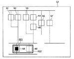
図2を用いて、注目点の位置毎に予め決定された注目領域の一例を説明する。図2は、第1の実施形態に係る注目点および注目領域の第1の例を示す図である。同図において、表示装置5に表示された画面G1の一例が示されている。画面G1中には、機器を表すノードN1〜N9が四角い枠で示され、各ノードN1〜N9の接続関係から、各機器がどのように接続されているかが分かる。同図の画面G1の例において、警告を通知するために点滅している領域R11が注目点で、矩形R12で示される領域が注目領域である。   An example of the attention area determined in advance for each position of the attention point will be described with reference to FIG. FIG. 2 is a diagram illustrating a first example of a point of interest and a region of interest according to the first embodiment. In the figure, an example of a screen G1 displayed on the display device 5 is shown. In the screen G1, nodes N1 to N9 representing devices are indicated by square frames, and it can be seen how the devices are connected from the connection relationship of the nodes N1 to N9. In the example of the screen G1 in the figure, a blinking region R11 for notifying a warning is the attention point, and a region indicated by a rectangle R12 is the attention region.

図2の例にように、注目領域検出部133は、領域R11の位置及び範囲を示す情報と矩形R12で示される領域の位置及び範囲を示す情報とを予め関連付けて保持する。そして、注目領域検出部133は、注目点検出部132が検出した注目点である領域R11の位置及び範囲を示す情報に対応する、矩形R12で示される領域の位置と範囲を示す情報を読み出し、読み出した情報により特定される画像領域を注目領域として検出する。   As illustrated in the example of FIG. 2, the attention area detection unit 133 holds information indicating the position and range of the area R11 and information indicating the position and range of the area indicated by the rectangle R12 in advance. Then, the attention area detection unit 133 reads information indicating the position and range of the area indicated by the rectangle R12 corresponding to the information indicating the position and range of the area R11 that is the attention point detected by the attention point detection unit 132, An image area specified by the read information is detected as an attention area.

なお、注目領域検出部133は、予め画面を複数の領域(以下、分割領域という)に分割しておき、注目点を含む分割領域を注目領域として検出してもよい。また例えば、注目領域検出部133は、第1の領域が含まれる画像領域が示すノードの接続関係に応じて、注目領域の位置及び範囲を決定してもよい。   Note that the attention area detection unit 133 may previously divide the screen into a plurality of areas (hereinafter referred to as divided areas) and detect a divided area including the attention point as the attention area. Further, for example, the attention area detection unit 133 may determine the position and range of the attention area according to the connection relationship of the nodes indicated by the image area including the first area.

図3を用いて、注目点が含まれるノードに応じて注目領域を決定する注目領域検出部133の処理の一例を説明する。図3は、第1の実施形態に係る注目点および注目領域の第2の例を示す図である。同図において、表示装置5に表示された画面G2の一例が示されている。画面G2中には、機器を表すノードN1〜N9が四角い枠で示され、各ノードN1〜N9の接続関係から、各機器がどのように接続されているかが分かる。同図の画面G2の例において、警告を通知するために点滅している領域R21が注目点で、矩形R22で示される領域が注目領域である。   An example of processing of the attention area detection unit 133 that determines the attention area according to the node including the attention point will be described using FIG. 3. FIG. 3 is a diagram illustrating a second example of a point of interest and a region of interest according to the first embodiment. In the figure, an example of a screen G2 displayed on the display device 5 is shown. In the screen G2, nodes N1 to N9 representing devices are indicated by square frames, and it can be seen how the devices are connected from the connection relationship of the nodes N1 to N9. In the example of the screen G2 in the figure, a blinking region R21 for notifying a warning is the attention point, and a region indicated by a rectangle R22 is the attention region.

図3の例にように、注目点がノードN8の画像領域に含まれる場合、注目領域検出部133が注目点を含むノードN8とそのノードに隣接するノードN9を含む領域を注目領域として検出する。その検出した結果、図3の例のように矩形R22で示される領域が注目領域として表示装置5に表示される。このように、注目領域検出部133は、注目点が含まれる画像領域が示すノードに隣接されているノードを含む画像領域を注目領域として検出してもよい。   As shown in the example of FIG. 3, when the attention point is included in the image area of the node N8, the attention area detection unit 133 detects the area including the node N8 including the attention point and the node N9 adjacent to the node as the attention area. . As a result of the detection, an area indicated by a rectangle R22 is displayed on the display device 5 as an attention area as in the example of FIG. As described above, the attention area detection unit 133 may detect an image area including a node adjacent to the node indicated by the image area including the attention point as the attention area.

図3の例では、あるノードに相当する機器に障害が発生すると、隣接するノードに相当する機器にも影響が及ぶため、注目点を含むノードとそのノードに隣接するノードを含む画像領域が注目領域として検出されている。そのため、図3に示すように注目点が注目領域の必ずしも中心になるとは限らず、注目点を含んで適切な注目領域が検出される。   In the example of FIG. 3, when a failure occurs in a device corresponding to a certain node, the device corresponding to the adjacent node is also affected. Therefore, the image region including the node including the point of interest and the node adjacent to the node is focused. It is detected as a region. Therefore, as shown in FIG. 3, the attention point is not necessarily the center of the attention area, and an appropriate attention area including the attention point is detected.

なお、注目領域検出部133は、注目点(第1の領域)における画像変化を検出し、該検出した画像変化に基づいて、注目領域(第2の領域)を検出してもよい。具体的には、注目領域検出部133は、画像変化から監視する対象となる機器で発生した障害に関する障害情報(例えば、障害の事象を示す情報)を検出し、その検出した障害情報に基づいて、注目領域(第2の領域)の位置及び範囲を決定してもよい。一例として障害情報が警告の種類を表す場合、注目領域検出部133は、画像変化から監視する対象となる機器に対する警告の種類を検出し、該検出した警告の種類に応じて、注目領域(第2の領域)の位置及び範囲を決定してもよい。具体的には例えば、注目領域検出部133は、警告の種類と注目領域の位置及び範囲とを関連付けた情報を予め保持しており、検出した警告の種類に対応する注目領域の位置及び範囲を読み出し注目領域と検出してもよい。   Note that the attention area detection unit 133 may detect an image change at the attention point (first area) and detect the attention area (second area) based on the detected image change. Specifically, the attention area detection unit 133 detects failure information (for example, information indicating a failure event) related to a failure that has occurred in a device to be monitored from an image change, and based on the detected failure information. The position and range of the attention area (second area) may be determined. As an example, when the failure information represents the type of warning, the attention area detection unit 133 detects the type of warning for the device to be monitored from the image change, and the attention area (first area) is determined according to the detected warning type. The position and range of (region 2) may be determined. Specifically, for example, the attention area detection unit 133 stores in advance information that associates the type of warning with the position and range of the attention area, and determines the position and range of the attention area corresponding to the detected warning type. You may detect with a read attention area.

また、注目領域検出部133は、画像変化が速いほど警告の緊急度が高いことを表す場合には、画像変化が速いほど注目領域(第2の領域)の範囲を大きくしてもよい。具体的には例えば、注目領域表示部134は、注目点の点滅速度が速いほど緊急度が高いことを表す場合に、点滅の速度が速いほど注目領域(第2の領域)の範囲を大きくしてもよい。これにより、注目領域検出部133は、警告の緊急度が高いほど、注目領域の範囲を大きくすることで、監視者の注意を引き易くすることができるので、監視者がその警告を見逃す可能性を下げることができる。   In addition, in a case where the attention area detection unit 133 indicates that the urgency of the warning is higher as the image change is faster, the attention area (second area) may be increased as the image change is faster. Specifically, for example, when the attention area display unit 134 indicates that the urgency is higher as the blinking speed of the attention point is higher, the attention area display unit 134 increases the range of the attention area (second area) as the blinking speed is faster. May be. As a result, the attention area detection unit 133 can easily attract the attention of the supervisor by increasing the range of the attention area as the urgency level of the warning is higher, so that the supervisor may miss the warning. Can be lowered.

また、注目領域検出部133は、注目点(第1の領域)における画像変化を検出し、その検出した画像変化と注目点の位置を示す情報とに基づいて、注目領域(第2の領域)を検出してもよい。これにより、画像変化が示す事象と注目点の位置を示す情報の双方を考慮して注目領域を検出するので、より適切な注目領域を検出することができる。   The attention area detection unit 133 detects an image change at the attention point (first area), and based on the detected image change and information indicating the position of the attention point, the attention area (second area). May be detected. Thereby, since the attention area is detected in consideration of both the event indicated by the image change and the information indicating the position of the attention point, a more appropriate attention area can be detected.

また、注目領域検出部133は、注目点(第1の領域)が複数検出された場合、その複数の注目点(第1の領域)の情報に基づいて、注目領域(第2の領域)を検出してもよい。例えば、注目領域検出部133は、注目点(第1の領域)が複数検出された場合、その複数の注目点(第1の領域)を含む領域を注目領域(第2の領域)として検出してもよい。
また、記憶部11が例えば、予めノード毎にそのノードで障害が発生した場合に影響を及ぼす影響波及ノードを関連付けた情報を保持しているという前提で、注目点が複数検出された場合に、注目領域検出部133は各注目点を含むノードに対する影響波及ノードを読み出してもよい。その場合に注目領域検出部133は、読み出した影響波及ノードそれぞれと各注目点を含むノードとを含む画像領域を注目領域として検出してもよい。
In addition, when a plurality of attention points (first regions) are detected, the attention region detection unit 133 determines the attention region (second region) based on information on the plurality of attention points (first regions). It may be detected. For example, when a plurality of attention points (first regions) are detected, the attention region detection unit 133 detects a region including the plurality of attention points (first regions) as the attention region (second region). May be.
Further, for example, when a plurality of attention points are detected on the assumption that the storage unit 11 holds information that associates an influence spreading node that affects when a failure occurs in each node in advance, for example, The attention area detection unit 133 may read an influence spreading node for a node including each attention point. In this case, the attention area detection unit 133 may detect an image area including each of the read influence spreading nodes and a node including each attention point as the attention area.

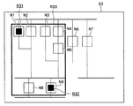
図4を用いて、その注目領域検出部133の処理の一例を説明する。図4は、第1の実施形態に係る注目点および注目領域の第3の例を示す図である。同図において、表示装置5に表示された画面G3の一例が示されている。画面G3中には、機器を表すノードN1〜N9が四角い枠で示され、各ノードN1〜N9の接続関係から、各機器がどのように接続されているかが分かる。同図の画面G3の例において、警告を通知するために点滅している領域R31が第1の注目点で、警告を通知するために点滅している領域R32が第2の注目点で、矩形R33で示される領域が注目領域である。   An example of processing of the attention area detection unit 133 will be described with reference to FIG. FIG. 4 is a diagram illustrating a third example of a point of interest and a region of interest according to the first embodiment. In the figure, an example of a screen G3 displayed on the display device 5 is shown. In the screen G3, nodes N1 to N9 representing devices are indicated by square frames, and it can be seen how the devices are connected from the connection relationship of the nodes N1 to N9. In the example of the screen G3 in the figure, a region R31 blinking for notifying a warning is a first attention point, and a region R32 blinking for notifying a warning is a second attention point. A region indicated by R33 is a region of interest.

図4では、第1の注目点としての領域R31がノードN1の画像領域に含まれ、かつ第2の注目点としての領域R32がノードN9の画像領域に含まれている。そして、例えば注目領域検出部133は、ノードN1の影響波及ノードとしてノードN2〜N5を保持し、ノードN9の影響波及ノードとしてノードN8を保持する。その場合、注目領域検出部133は一例として、図4の矩形R33で示される、ノードN1〜N5とノードN8〜N9を含む領域を注目領域として検出する。その検出した結果、図4の例のように矩形R33で示される領域が注目領域として表示装置5に表示される。   In FIG. 4, the region R31 as the first point of interest is included in the image region of the node N1, and the region R32 as the second point of interest is included in the image region of the node N9. For example, the attention area detection unit 133 holds the nodes N2 to N5 as the influence spreading node of the node N1, and holds the node N8 as the influence spreading node of the node N9. In this case, the attention area detection unit 133 detects, as an example, an area including nodes N1 to N5 and nodes N8 to N9, which is indicated by a rectangle R33 in FIG. 4, as the attention area. As a result of the detection, a region indicated by a rectangle R33 is displayed on the display device 5 as a region of interest as in the example of FIG.

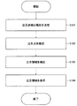
図5は、第1の実施形態に係る画像処理装置の処理の流れの一例を示すフローチャートである。
(ステップS101)まず、第一の決定部131は、注目点検出規則を決定する。ここでは一例として、第一の決定部131は、アプリケーション実行部12から通知された注目点情報により特定される領域を注目点として検出するという注目点検出規則を決定する。
(ステップS102)次に、注目点検出部132は例えば、第一の決定部131から入力された注目点検出規則に従い、アプリケーション実行部12から通知された注目点情報により特定される領域を注目点として検出する。
FIG. 5 is a flowchart illustrating an example of a processing flow of the image processing apparatus according to the first embodiment.
(Step S101) First, the first determination unit 131 determines a target point detection rule. Here, as an example, the first determination unit 131 determines an attention point detection rule of detecting, as an attention point, an area specified by attention point information notified from the application execution unit 12.
(Step S102) Next, the point-of-interest detection unit 132 follows the point-of-interest detection rule input from the first determination unit 131, for example, and selects an area specified by the point-of-interest information notified from the application execution unit 12 as the point of interest. Detect as.

(ステップS103)次に、注目領域検出部133は、注目点検出部132が検出した注目点情報に応じて注目領域を検出する。ここでは一例として、注目領域検出部133は、注目点情報と注目領域の位置及び範囲とを予め関連付けた情報を保持し、注目点に対応する注目領域を当該情報から特定する。
(ステップS104)次に、注目領域表示部134は、注目領域検出部133が検出しした注目領域の位置及び範囲を表す情報を表示装置5に表示させる。例えば注目領域表示部134は、注目領域の外縁を示す赤い矩形を表示装置5に描画する。
(Step S103) Next, the attention area detection unit 133 detects the attention area in accordance with the attention point information detected by the attention point detection section 132. Here, as an example, the attention area detection unit 133 holds information in which attention point information and the position and range of the attention area are associated in advance, and identifies the attention area corresponding to the attention point from the information.
(Step S104) Next, the attention area display unit 134 causes the display device 5 to display information indicating the position and range of the attention area detected by the attention area detection unit 133. For example, the attention area display unit 134 draws a red rectangle indicating the outer edge of the attention area on the display device 5.

このように、第1の実施形態に係る画像処理装置1は、アプリケーションから与えられた注目点情報で特定される画像領域を注目点とし、注目点の位置毎に予め決定された注目領域を検出し、検出した注目領域の位置及び範囲を表す情報を表示装置5に表示する。これにより、表示装置5に事象の状況を知らせるのに適切な注目領域が表示されることで、監視者は注目領域を確認するだけで注目すべき事象の状況を容易に把握することができるので、監視者がその状況を把握できる可能性を向上させることができる。   As described above, the image processing apparatus 1 according to the first embodiment detects an attention area determined in advance for each position of the attention point, with the image area specified by the attention point information given from the application as the attention point. Then, information indicating the position and range of the detected attention area is displayed on the display device 5. As a result, the attention area appropriate for notifying the situation of the event is displayed on the display device 5, so that the supervisor can easily grasp the situation of the event to be noticed only by confirming the attention area. The possibility that the supervisor can grasp the situation can be improved.

(第2の実施形態)
続いて、第2の実施形態について説明する。第1の実施形態に係る画像処理装置1は一例として、アプリケーション実行部11から与えられた位置情報を注目点とし、位置ごとに予め定められた注目領域を検出した。第2の実施形態では、画像処理装置1bが、ユーザにより操作された領域を注目点とし、注目点とユーザの操作の結果生じた画面変化領域とを含む注目領域を検出する例を説明する。
(Second Embodiment)
Next, the second embodiment will be described. As an example, the image processing apparatus 1 according to the first embodiment uses the position information given from the application execution unit 11 as a point of interest, and detects a region of interest predetermined for each position. In the second embodiment, an example will be described in which the image processing apparatus 1b detects a region of interest including a region operated by a user as a point of interest and a point of interest and a screen change region generated as a result of the user's operation.

図6は、第2の実施形態に係る画像処理システム102の構成を示す概略ブロック図である。なお、図1と共通する要素には同一の符号を付し、その具体的な説明を省略する。画像処理システム102は画像処理装置1bと端末装置3とを具備する。画像処理装置1bは通信回路網2を介して端末装置3と接続されている。   FIG. 6 is a schematic block diagram illustrating a configuration of the image processing system 102 according to the second embodiment. Elements common to those in FIG. 1 are denoted by the same reference numerals, and detailed description thereof is omitted. The image processing system 102 includes an image processing device 1 b and a terminal device 3. The image processing device 1 b is connected to the terminal device 3 via the communication network 2.

第2の実施形態に係る画像処理装置1bの構成は、第1の実施形態に係る画像処理装置1の構成に対して、記憶部11が記憶部11bに、アプリケーション実行部12がアプリケーション実行部12bに、ウィンドウ処理部13がウィンドウ処理部13bに変更され、入力部14と通信部(第1の通信部)15が追加されたものになっている。
記憶部11bは、第1の実施形態に係る記憶部11に比べて、規則記憶部111が規則記憶部111bに変更され、更にフレームバッファ112が追加された構成になっている。
The configuration of the image processing apparatus 1b according to the second embodiment is different from the configuration of the image processing apparatus 1 according to the first embodiment in that the storage unit 11 is the storage unit 11b and the application execution unit 12 is the application execution unit 12b. Furthermore, the window processing unit 13 is changed to a window processing unit 13b, and an input unit 14 and a communication unit (first communication unit) 15 are added.
Compared to the storage unit 11 according to the first embodiment, the storage unit 11b has a configuration in which the rule storage unit 111 is changed to the rule storage unit 111b and a frame buffer 112 is further added.

規則記憶部111bは、第1の実施形態の規則記憶部111と比べて、更に画像内の注目点(第1の領域)からどのように注目領域(第2の領域)を検出するかの規則(以下、注目領域検出規則ともいう)が予め記憶されている点が異なる。
フレームバッファ112は、画像情報を記憶可能であり、ウィンドウ処理部13bの後述する描画部135が描画した画像情報を描画部135から受け取り、受け取った画像情報を保持する。
The rule storage unit 111b further determines how to detect a region of interest (second region) from a point of interest (first region) in the image, as compared to the rule storage unit 111 of the first embodiment. (Hereinafter also referred to as an attention area detection rule) is stored in advance.
The frame buffer 112 can store image information, receives image information drawn by a drawing unit 135 (to be described later) of the window processing unit 13b from the drawing unit 135, and holds the received image information.

入力部14は、ユーザによる操作(例えば、マウスカーソルの移動やマウスクリックなど)を検出し、ユーザの操作により入力された入力情報をウィンドウ処理部13bの後述する注目点検出部132bへ出力する。ここで入力部14は一例としてマウスであり、入力情報は例えば、ユーザが操作したユーザ操作領域(例えば、ユーザがマウスクリックした位置)を示すユーザ操作領域情報である。
アプリケーション実行部12bは、第1の実施形態におけるアプリケーション実行部12と同様の機能を有するが、描画命令を描画部135へ出力する点が異なる。
The input unit 14 detects an operation (for example, movement of a mouse cursor, mouse click, etc.) by a user, and outputs input information input by the user's operation to an attention point detection unit 132b described later of the window processing unit 13b. Here, the input unit 14 is a mouse as an example, and the input information is, for example, user operation area information indicating a user operation area operated by the user (for example, a position where the user clicked the mouse).
The application execution unit 12b has the same function as the application execution unit 12 in the first embodiment, but differs in that a drawing command is output to the drawing unit 135.

ウィンドウ処理部13bは、第1の実施形態におけるウィンドウ処理部13に比べて、描画部135と第二の決定部136とが追加され、第一の決定部131が第一の決定部131bに、注目点検出部132が注目点検出部132bに、注目領域検出部133が注目領域検出部133bに、注目領域表示部134が画像生成部(出力処理部)137に変更されたものになっている。   As compared with the window processing unit 13 in the first embodiment, the window processing unit 13b includes a drawing unit 135 and a second determination unit 136, and the first determination unit 131 is replaced with the first determination unit 131b. The attention point detection unit 132 is changed to an attention point detection unit 132b, the attention region detection unit 133 is changed to an attention region detection unit 133b, and the attention region display unit 134 is changed to an image generation unit (output processing unit) 137. .

規則記憶部111bには一例として、ユーザが操作したユーザ操作領域を注目点として検出するという注目点検出規則が記憶されている。第一の決定部131bは一例として、規則記憶部111bから使用する注目点検出規則を読み出し、読み出した注目点検出規則を注目点検出部132bへ出力する。
注目点検出部132bは一例として、第一の決定部131bから入力された注目点検出規則に従って、入力部14から入力された入力情報(ここでは、一例としてユーザ操作領域情報)から、ユーザが操作したユーザ操作領域を注目点として検出する。注目点検出部132bは検出した注目点の位置及び範囲を示す注目点情報を注目領域検出部133bへ出力する。
As an example, the rule storage unit 111b stores an attention point detection rule for detecting a user operation area operated by a user as an attention point. As an example, the first determination unit 131b reads the attention point detection rule used from the rule storage unit 111b, and outputs the read attention point detection rule to the attention point detection unit 132b.
For example, the attention point detection unit 132b is operated by the user from input information (here, user operation area information as an example) input from the input unit 14 in accordance with the attention point detection rule input from the first determination unit 131b. The detected user operation area is detected as a point of interest. The attention point detection unit 132b outputs attention point information indicating the position and range of the detected attention point to the attention region detection unit 133b.

描画部135は、アプリケーション実行部12bから描画命令を受け取り、受け取った描画命令に従い各種画像処理を行った結果の画像情報を記憶部11bのフレームバッファに記憶させる。また、描画部135は、描画により特定の画面変化が発生した領域の位置及び範囲を示す描画情報を注目領域検出部133bへ出力する。具体的には図7の例において、描画部135は例えば、入力部14がユーザによる「故障」ボタンを押す操作を受け付けた場合に、表示させるエラーログの画像領域(図7の領域R42)の位置及び範囲を示す情報を注目領域検出部133bへ出力する。   The drawing unit 135 receives a drawing command from the application execution unit 12b, and stores image information obtained as a result of performing various image processing in accordance with the received drawing command in the frame buffer of the storage unit 11b. In addition, the drawing unit 135 outputs drawing information indicating the position and range of an area where a specific screen change has occurred due to drawing to the attention area detection unit 133b. Specifically, in the example of FIG. 7, for example, the drawing unit 135 displays an error log image region (region R <b> 42 in FIG. 7) to be displayed when the input unit 14 receives an operation of pressing the “fault” button by the user. Information indicating the position and range is output to the attention area detection unit 133b.

第二の決定部136は、注目領域検出規則を決定する。例えば第二の決定部136は、注目領域検出規則を規則記憶部111bから読み出し、読み出した注目領域検出規則を注目領域検出部133bへ出力する。ここでは注目領域検出規則は一例として、描画部135が描画することにより特定の画面変化が発生した領域と注目点検出部132bが検出した注目点(第1の領域)とを含む領域を注目領域(第2の領域)として検出するという規則である。   The second determination unit 136 determines the attention area detection rule. For example, the second determination unit 136 reads the attention area detection rule from the rule storage unit 111b, and outputs the read attention area detection rule to the attention area detection unit 133b. Here, as an example of the attention area detection rule, an area including an area where a specific screen change has occurred due to drawing by the drawing unit 135 and an attention point (first area) detected by the attention point detection unit 132b is the attention area. This is a rule of detecting as (second region).

注目領域検出部133bは例えば、第二の決定部136が決定した注目領域検出規則に従って、注目点検出部132bから入力された注目点情報に基づき、注目領域(第2の領域)を検出する。例えば注目領域検出部133bは、第二の決定部136が決定した注目領域検出規則に従って、描画部135が描画することにより特定の画面変化が発生した領域と注目点検出部132bが検出した注目点(第1の領域)とを含む領域を注目領域(第2の領域)として検出する。具体的には例えば、図7の例の場合、特定の画面変化が発生した領域は、エラーログの画像領域(図7の領域R42)であり、注目領域検出部133bは、エラーログの画像領域と注目点であるユーザの操作領域(図7の領域R41参照)とを含む画像領域R43を注目領域として検出する。注目領域検出部133bは、検出した注目領域の位置及び範囲を示す注目領域情報を画像生成部137へ出力する。   The attention area detector 133b detects the attention area (second area) based on the attention point information input from the attention point detection section 132b, for example, according to the attention area detection rule determined by the second determination section 136. For example, the attention area detection unit 133b, according to the attention area detection rule determined by the second determination unit 136, the area where a specific screen change has occurred due to the drawing unit 135 drawing and the attention point detected by the attention point detection unit 132b. A region including (first region) is detected as a region of interest (second region). Specifically, for example, in the case of the example in FIG. 7, the region where the specific screen change has occurred is an error log image region (region R <b> 42 in FIG. 7), and the attention region detection unit 133 b And an image region R43 including the user's operation region (see region R41 in FIG. 7), which is the attention point, is detected as the attention region. The attention area detection unit 133b outputs attention area information indicating the position and range of the detected attention area to the image generation unit 137.

画像生成部137は、注目領域検出部133が検出した注目領域の情報に基づいて、画像に対する出力処理を行う出力処理部として機能する。画像生成部137は、注目領域検出部133bから入力された注目領域情報を用いて注目領域の画像情報をフレームバッファ112から読み出し、読み出した画像情報を通信部15から端末装置3へ送信させる。
なお、画像生成部137は、この画像情報を、圧縮してもよい。また、画像生成部137は、端末装置3の画面サイズに合わせて画像情報が示す画像を拡大または縮小してもよい。
The image generation unit 137 functions as an output processing unit that performs output processing on an image based on the information on the attention area detected by the attention area detection unit 133. The image generation unit 137 reads the image information of the attention area from the frame buffer 112 using the attention area information input from the attention area detection unit 133b, and causes the communication unit 15 to transmit the read image information to the terminal device 3.
Note that the image generation unit 137 may compress this image information. The image generation unit 137 may enlarge or reduce the image indicated by the image information in accordance with the screen size of the terminal device 3.

通信部15は、画像生成部137が生成した画像情報を端末装置3へ送信する。ここで通信部15による通信は有線であっても無線であってもよい。なお、通信部15は、画像情報を送信するだけでもよいし、端末装置3から画像情報に対する操作を示す情報を受信してもよい。
また、通信部15は、例えば、端末装置3の宛先を示す宛先情報(例えば、IPアドレス)を記憶部11bのデータベースに登録しておき、通信部15が記憶部11bのデータベースから宛先情報を取得することで送信先の端末装置3の宛先を特定する。なお、通信部15は、送信先の端末装置3を、時間帯や注目領域ごとに変更してもよい。また、送信先の端末装置3が複数あってもよい。
The communication unit 15 transmits the image information generated by the image generation unit 137 to the terminal device 3. Here, the communication by the communication unit 15 may be wired or wireless. The communication unit 15 may only transmit image information, or may receive information indicating an operation on the image information from the terminal device 3.
For example, the communication unit 15 registers destination information (for example, IP address) indicating the destination of the terminal device 3 in the database of the storage unit 11b, and the communication unit 15 acquires the destination information from the database of the storage unit 11b. By doing so, the destination of the terminal device 3 of the transmission destination is specified. Note that the communication unit 15 may change the destination terminal device 3 for each time zone or attention area. Further, there may be a plurality of transmission destination terminal devices 3.

端末装置3は、通信部(第2の通信部)31、処理部32及び表示部33を備える。
通信部31は、通信部15が送信した画像情報を受信し、受信した画像情報を処理部32へ出力する。処理部32は、通信部31が受信した画像情報を表示部33に表示させる。これにより、表示部33は、通信部31が受信した画像情報に基づいて、注目領域(第2の領域)の画像を表示する。
また、端末装置3は、画像情報を、特定のアプリケーションで表示してもよいし、メールで表示してもよいし、ブラウザで表示してもよい。なお、端末装置3は、表示部33の画面サイズに合わせて、画像情報を拡大または縮小してもよい。
The terminal device 3 includes a communication unit (second communication unit) 31, a processing unit 32, and a display unit 33.
The communication unit 31 receives the image information transmitted by the communication unit 15 and outputs the received image information to the processing unit 32. The processing unit 32 causes the display unit 33 to display the image information received by the communication unit 31. Thereby, the display unit 33 displays the image of the attention area (second area) based on the image information received by the communication unit 31.
The terminal device 3 may display the image information with a specific application, may be displayed with an email, or may be displayed with a browser. Note that the terminal device 3 may enlarge or reduce the image information according to the screen size of the display unit 33.

図7は、第2の実施形態における注目点および注目領域の例を示す図である。同図は表示装置5に表示された画面G4を監視者が確認し、端末装置3に表示された画面G5を現場の作業員が確認している例である。同図では、「故障」と表示されている画像領域をマウスでクリックすると、故障の詳細であるエラーログが表示されるアプリケーションの画面G4の例が示されている。画面G4の向かって左上端がij座標の原点である。同図の例では、ユーザがマウスでクリックした領域R41を注目点とし、注目点とエラーログの画像領域R42を含む領域を注目領域としている。なお、図7では分かりやすくするために領域R41が示されているが、領域R41は実際の画面には表示される必要はない。画面G4には、注目領域の外縁を示す枠R43が表示されている。注目領域の外縁を示す枠R43がエラーログも含むように表示されることで、監視者の注意がエラーログに向くので、監視者がエラーログを見逃す可能性を下げることができ、監視者が故障の詳細を把握できる可能性を向上させることができる。   FIG. 7 is a diagram illustrating an example of attention points and attention areas in the second embodiment. This figure shows an example in which the supervisor confirms the screen G4 displayed on the display device 5 and the worker on site confirms the screen G5 displayed on the terminal device 3. The figure shows an example of an application screen G4 in which an error log, which is details of a failure, is displayed when an image area displayed as “failure” is clicked with a mouse. The upper left corner of the screen G4 is the ij coordinate origin. In the example shown in the figure, an area R41 clicked by the user with the mouse is set as the attention point, and an area including the attention point and the error log image area R42 is set as the attention area. In FIG. 7, the region R41 is shown for the sake of clarity, but the region R41 need not be displayed on the actual screen. On the screen G4, a frame R43 indicating the outer edge of the attention area is displayed. Since the frame R43 indicating the outer edge of the attention area is displayed so as to include the error log, the attention of the monitor is directed to the error log, so that the possibility that the monitor misses the error log can be reduced. The possibility of grasping the details of the failure can be improved.

また、図7において、注目領域の画像情報が通信回路網を介して画像処理装置1bから端末装置3へ送信され、端末装置3の画面G5に、注目領域の画像情報が表示されている。これにより、端末装置3の画面には、エラーログも含むように表示されることで、端末装置3のユーザ(例えば、現場の作業員)はエラーログから故障の詳細を把握することができる。   In FIG. 7, the image information of the attention area is transmitted from the image processing device 1 b to the terminal device 3 via the communication network, and the image information of the attention area is displayed on the screen G <b> 5 of the terminal device 3. Thereby, the screen of the terminal device 3 is displayed so as to include the error log, so that the user of the terminal device 3 (for example, an on-site worker) can grasp the details of the failure from the error log.

なお、注目領域検出部133bは、注目点を含むHTML要素に相当する領域を注目領域としてもよい。ここでHTML要素は開始タグ、内容及び終了タグの三つから構成される。例えば、図7の例のアプリケーションがウェブアプリケーションとして作られており、正常/故障情報、運用/停止情報、装置名、ログ情報が、装置ごとに1つのDiv要素によってグループ化されている場合を想定する。ここで、Div要素は、HTML要素の一例であり、区切りを意味するブロック要素である。その想定で、注目領域検出部133bは、アプリケーション実行部12bから、Div要素に相当する領域ごとの位置および範囲を取得して、注目点を含むDiv要素を注目領域としてもよい。例えば、図7の例では、注目領域検出部133bは、アプリケーション実行部12bから、装置A、装置B、装置Cに対応する3つのDiv要素が通知され、注目点を含む、装置Aに対応するDiv要素に相当する領域を注目領域として検出してもよい。   Note that the attention area detection unit 133b may use an area corresponding to the HTML element including the attention point as the attention area. Here, the HTML element is composed of a start tag, a content, and an end tag. For example, it is assumed that the application in the example of FIG. 7 is created as a web application, and normal / failure information, operation / stop information, device name, and log information are grouped by one Div element for each device. To do. Here, the Div element is an example of an HTML element, and is a block element that means a delimiter. Under the assumption, the attention area detection unit 133b may acquire the position and range for each area corresponding to the Div element from the application execution unit 12b, and may use the Div element including the attention point as the attention area. For example, in the example of FIG. 7, the attention area detection unit 133b is notified of three Div elements corresponding to the devices A, B, and C from the application execution unit 12b, and corresponds to the device A including the attention point. An area corresponding to the Div element may be detected as the attention area.

その場合、記憶部11bには例えば、Div要素毎にDiv要素に相当する領域の位置及び範囲の情報が記憶され、ユーザが操作可能な画像領域である操作可能領域毎にDiv要素が関連付けられて記憶されていてもよい。そして、注目領域検出部133bは、ユーザが操作した領域が注目領域(第1領域)として検出された場合、記憶部11bを参照して、その注目領域を包含する操作可能領域に対応するDiv要素を特定してもよい。そして注目領域検出部133bは、特定したDiv要素に相当する領域の位置と注目領域を包含する操作可能領域とを含む領域を前記第2の領域として検出してもよい。なお、ここでは一例としてDiv要素について説明したが、他のHTML要素についても適用可能である。   In this case, for example, the position and range information of the area corresponding to the Div element is stored for each Div element, and the Div element is associated with each operable area that is an image area that can be operated by the user. It may be stored. Then, when the region operated by the user is detected as the attention region (first region), the attention region detection unit 133b refers to the storage unit 11b and refers to the Div element corresponding to the operable region that includes the attention region. May be specified. The attention area detection unit 133b may detect, as the second area, an area including the position of the area corresponding to the specified Div element and the operable area including the attention area. Although the Div element is described here as an example, the present invention can also be applied to other HTML elements.

また、装置が故障すると自動的にエラーメッセージが表示され、「故障」と表示されている領域をクリックすると装置の設定を変更できるアプリケーションの例の場合、注目領域検出部133bは、画面変化領域(ここでは例えば、エラーメッセージの表示領域)を注目点とし、注目点と操作可能領域を含む領域を注目領域としてもよい。これにより、注目領域検出部133bは、図7と同一の注目領域を検出することができる。   Also, in the case of an example of an application in which an error message is automatically displayed when a device breaks down and the setting of the device can be changed by clicking on the area where “failure” is displayed, the attention area detection unit 133b displays the screen change area ( Here, for example, an error message display area) may be set as the attention point, and an area including the attention point and the operable area may be set as the attention area. Thereby, the attention area detection unit 133b can detect the same attention area as that in FIG.

図8は、第2の実施形態に係る画像処理装置の処理の流れの一例を示すフローチャートである。
(ステップS201)まず、第一の決定部131bは、使用する注目点検出規則を規則記憶部111bから読み出す。ここでは一例として、第一の決定部131bは、ユーザが操作した領域を注目点として検出するという注目点検出規則に決定する。
(ステップS202)次に、入力部14が、入力情報を注目点検出部132bへ通知する。例えば、入力部14は、図7の画面上の座標(50、50)の位置でマウスクリックが発生したことを注目点検出部132bへ通知する。
FIG. 8 is a flowchart illustrating an example of a processing flow of the image processing apparatus according to the second embodiment.
(Step S201) First, the first determination unit 131b reads the attention point detection rule to be used from the rule storage unit 111b. Here, as an example, the first determination unit 131b determines an attention point detection rule that detects an area operated by the user as an attention point.
(Step S202) Next, the input unit 14 notifies the attention point detection unit 132b of the input information. For example, the input unit 14 notifies the attention point detection unit 132b that a mouse click has occurred at the position of the coordinates (50, 50) on the screen of FIG.

(ステップS203)次に、注目点検出部132bは、入力部14が検出したユーザ操作領域を注目点として検出する。例えば、注目点検出部132bは、マウスクリックが発生した画面上の座標(50、50)の位置を注目点として検出する。
(ステップS204)次に、第二の決定部136は、使用する注目領域検出規則を規則記憶部111bから読み出す。
(ステップS205)次に、描画部135は、画面変化領域(例えば、図7のエラーログの画像領域R42)の位置と範囲を示す描画情報を注目領域検出部133bに通知する。例えば描画部135は、図7の画面上の座標(30、200)から幅150ピクセル、高さ50ピクセルの領域に描画が発生したことを注目領域検出部133bに通知する。
(Step S203) Next, the attention point detection unit 132b detects the user operation area detected by the input unit 14 as the attention point. For example, the attention point detection unit 132b detects the position of the coordinates (50, 50) on the screen where the mouse click has occurred as the attention point.
(Step S204) Next, the second determination unit 136 reads the attention area detection rule to be used from the rule storage unit 111b.
(Step S205) Next, the drawing unit 135 notifies the attention area detection unit 133b of drawing information indicating the position and range of the screen change area (for example, the image area R42 of the error log in FIG. 7). For example, the drawing unit 135 notifies the attention area detection unit 133b that drawing has occurred in an area having a width of 150 pixels and a height of 50 pixels from the coordinates (30, 200) on the screen in FIG.

(ステップS206)次に、注目領域検出部133bは、ユーザ操作領域と画面変化領域(例えば、図7のエラーログの画像領域R42)と含む画像領域を注目領域として検出する。例えば、注目領域検出部133bは、図7の画面上の座標(30、50)から幅150ピクセル、高さ200ピクセルの領域を注目領域として検出する。
(ステップS207)次に、画像生成部1377は、注目領域に対応する画像情報をフレームバッファ112から取得し、必要に応じて圧縮処理を行って、画像情報を生成する。例えば、画像生成部137は、端末装置3の処理能力が低い場合やネットワークの品質が悪い場合だけ画像情報を圧縮してもよい。
(ステップS208)次に、通信部15は、画像生成部137が生成した画像情報を端末装置3へ送信する。
(Step S206) Next, the attention area detection unit 133b detects an image area including the user operation area and the screen change area (for example, the image area R42 of the error log in FIG. 7) as the attention area. For example, the attention area detection unit 133b detects an area having a width of 150 pixels and a height of 200 pixels as the attention area from the coordinates (30, 50) on the screen in FIG.
(Step S207) Next, the image generation unit 1377 acquires image information corresponding to the region of interest from the frame buffer 112, performs compression processing as necessary, and generates image information. For example, the image generation unit 137 may compress the image information only when the processing capability of the terminal device 3 is low or when the network quality is poor.
(Step S208) Next, the communication unit 15 transmits the image information generated by the image generation unit 137 to the terminal device 3.

このように、第2の実施形態に係る画像処理装置1bは、ユーザが操作したユーザ操作領域を注目点とし、注目点とユーザが操作したことによって生じた画面変化の画像領域を含む注目領域を検出し、検出した注目領域に対応する画像情報を端末装置3へ送信する。これにより、端末装置3が画像処理装置1bから離れていたとしても、端末装置3のユーザ(例えば、現場の作業員)は、注目すべき事象の状況(例えば、特定の装置の故障の詳細)を容易に把握することができる。   As described above, the image processing apparatus 1b according to the second embodiment uses the user operation area operated by the user as the attention point, and selects the attention area including the attention point and the image area of the screen change caused by the user's operation. The image information corresponding to the detected attention area is transmitted to the terminal device 3. As a result, even if the terminal device 3 is separated from the image processing device 1b, the user of the terminal device 3 (for example, an on-site worker) is able to notice the situation of the event (for example, details of the failure of a specific device). Can be easily grasped.

なお、第2の実施形態では、注目領域検出部133bは、描画部135が描画することにより特定の画面変化が発生した領域と注目点検出部132bが検出した注目点(第1の領域)とを含む領域を注目領域(第2の領域)として検出したが、これに限ったものではない。注目領域検出部133bは、例えば、注目点を含むウィンドウを注目領域としてもよいし、注目点を含むHTML要素を注目領域としてもよいし、注目点と画面変化領域を含む領域を注目領域としてもよいし、注目点と操作可能領域を含む領域を注目領域としてもよい。なお、操作可能領域とは、キー入力やクリック操作などの操作が可能な領域を指す。   Note that in the second embodiment, the attention area detection unit 133b includes an area where a specific screen change has occurred due to drawing by the drawing unit 135 and an attention point (first area) detected by the attention point detection unit 132b. Although the region including is detected as the attention region (second region), the present invention is not limited to this. The attention area detection unit 133b may use, for example, a window including the attention point as the attention area, an HTML element including the attention point as the attention area, or an area including the attention point and the screen change area as the attention area. Alternatively, an area including the attention point and the operable area may be set as the attention area. The operable area refers to an area where operations such as key input and click operation are possible.

また、記憶部11bがユーザによる操作が可能な操作可能領域を記憶する操作可能領域記憶部を備えていてもよい。その場合に、注目領域検出部133bは、ユーザが操作した領域を包含する操作可能領域を含む領域と特定の画面変化が発生した領域とを含む領域を注目領域(第2の領域)として検出してもよい。   The storage unit 11b may include an operable area storage unit that stores an operable area that can be operated by the user. In this case, the attention area detection unit 133b detects, as an attention area (second area), an area including an operable area that includes an area operated by the user and an area where a specific screen change has occurred. May be.

また、注目領域検出部133bによる注目領域決定処理は上述したものだけに限ったものではない。注目領域検出部133bは、例えば、注目点の位置や種類に応じて注目領域を決定してもよいし、アプリケーションの種類に応じて決定してもよいし、クライアントの処理能力や画面サイズに応じて決定してもよいし、ネットワークの品質に応じて決定してもよい。   Further, the attention area determination processing by the attention area detection unit 133b is not limited to the above-described one. The attention area detection unit 133b may determine the attention area according to, for example, the position and type of the attention point, may be determined according to the type of application, or may be determined according to the processing capability and screen size of the client. Or may be determined according to the quality of the network.

(第3の実施形態)
続いて、第3の実施形態について説明する。第3の実施形態では、特定の画面変化が発生した領域を注目点とし、注目点を含むウィンドウを注目領域として検出する例について説明する。
図9は、第3の実施形態に係る画像処理システム103の構成を示す概略ブロック図である。なお、図6と共通する要素には同一の符号を付し、その具体的な説明を省略する。画像処理システム103は、画像処理装置1c、画面転送サーバ(画面転送装置)4−1、…、4−N(Nは正の整数)及び端末装置3を具備する。画像処理装置1cは通信回路網2を介して、画面転送サーバ4−1、…、4−N及び端末装置3と接続されている。
(Third embodiment)
Subsequently, a third embodiment will be described. In the third embodiment, an example will be described in which a region where a specific screen change has occurred is set as a target point, and a window including the target point is detected as a target region.
FIG. 9 is a schematic block diagram showing the configuration of the image processing system 103 according to the third embodiment. In addition, the same code | symbol is attached | subjected to the element which is common in FIG. 6, and the specific description is abbreviate | omitted. The image processing system 103 includes an image processing device 1c, a screen transfer server (screen transfer device) 4-1,..., 4-N (N is a positive integer) and a terminal device 3. The image processing device 1 c is connected to the screen transfer servers 4-1,..., 4-N and the terminal device 3 via the communication network 2.

例えば、画面転送サーバ4−1、…、4−Nはそれぞれ、機器を監視する監視画面を保持する。そして、例えば画面転送サーバ4−1、…、4−Nはそれぞれ、現在の監視画面と所定の時間だけ直前の監視画面とで異なる画素値を示す領域を抽出する。これにより、画面転送サーバ4−1、…、4−Nは点滅している画像領域を抽出することができる。そして、画面転送サーバ4−1、…、4−Nはそれぞれ、抽出した領域の画像情報(以下、領域画像情報ともいう)とその領域の画像内における位置との組を画像処理装置1cへ通信回路網2を介して送信する。これにより、画像処理装置1cはフレームバッファ112上で各監視画面をそれぞれ異なるウィンドウで描画することができる。例えば画面転送サーバ4−1、…、4−Nそれぞれは、所定の時間が経過する毎に上述した処理を繰り返す。
端末装置3の構成は、第2の実施形態に係る端末装置3の構成と同様であるので、ここでの説明は省略する。
For example, each of the screen transfer servers 4-1,..., 4-N holds a monitoring screen for monitoring the device. Then, for example, each of the screen transfer servers 4-1,. Thereby, the screen transfer servers 4-1,..., 4-N can extract the blinking image area. Then, each of the screen transfer servers 4-1,..., 4-N communicates the set of the image information of the extracted area (hereinafter also referred to as area image information) and the position of the area in the image to the image processing apparatus 1c. Transmit via the network 2. As a result, the image processing apparatus 1c can draw each monitoring screen on the frame buffer 112 in different windows. For example, each of the screen transfer servers 4-1,..., 4-N repeats the above-described processing every time a predetermined time elapses.
Since the configuration of the terminal device 3 is the same as the configuration of the terminal device 3 according to the second embodiment, a description thereof is omitted here.

第3の実施形態に係る画像処理装置1cの構成は、第2の実施形態に係る画像処理装置1bの構成に対して、記憶部11bが記憶部11cに、アプリケーション実行部12bがアプリケーション実行部12cに、ウィンドウ処理部13bがウィンドウ処理部13cに、通信部15が通信部15cに変更されたものになっている。   The configuration of the image processing apparatus 1c according to the third embodiment is different from the configuration of the image processing apparatus 1b according to the second embodiment in that the storage unit 11b is the storage unit 11c and the application execution unit 12b is the application execution unit 12c. Further, the window processing unit 13b is changed to the window processing unit 13c, and the communication unit 15 is changed to the communication unit 15c.

記憶部11cは、第2の実施形態に係る記憶部11bに比べて、ウィンドウ情報記憶部113が追加された構成になっている。
ウィンドウ情報記憶部113は、フレームバッファ112上の各ウィンドウの表示位置、表示サイズ及び表示領域などを含むウィンドウ情報を保持する。ここで、表示位置はフレームバッファ112内における座標を表し、表示サイズはウィンドウの幅及び高さを表し、表示領域はフレームバッファ112上に実際に表示する領域を表す。図10の例ではウィンドウW7の表示領域は例えば、ウィンドウW7の領域のうちウィンドウW6によって隠れた領域を除く領域である。
The storage unit 11c has a configuration in which a window information storage unit 113 is added compared to the storage unit 11b according to the second embodiment.
The window information storage unit 113 holds window information including the display position, display size, display area, and the like of each window on the frame buffer 112. Here, the display position represents coordinates in the frame buffer 112, the display size represents the width and height of the window, and the display area represents an area actually displayed on the frame buffer 112. In the example of FIG. 10, the display area of the window W7 is, for example, an area excluding the area hidden by the window W6 from the area of the window W7.

通信部15cは、画面転送サーバ4−1、…、4−Nから送信された、領域画像情報とその領域の画像内における位置の組を受信し、受信した領域画像をアプリケーション実行部12cへ出力する。
アプリケーション実行部12cは、通信部15cから入力された領域画像情報すなわち画面転送サーバ4−1、…、4−Nから取得した領域画像情報を描画する描画命令を描画部135へ出力する。
The communication unit 15c receives the set of the region image information and the position in the image of the region transmitted from the screen transfer server 4-1, ..., 4-N, and outputs the received region image to the application execution unit 12c. To do.
The application execution unit 12c outputs to the drawing unit 135 a drawing command for drawing the region image information input from the communication unit 15c, that is, the region image information acquired from the screen transfer servers 4-1,.

ウィンドウ処理部13cは、第2の実施形態のウィンドウ処理部13bに対して、第一の決定部131bが第一の決定部131cに、注目点検出部132bが注目点検出部132cに、注目領域検出部133bが注目領域検出部133cに、第二の決定部136が第二の決定部136cに変更され、画面取得部138が追加されたものになっている。その他の構成は、第2の実施形態に係る画像処理装置1bの構成と同様であるので、ここでの説明は省略する。   The window processing unit 13c is different from the window processing unit 13b of the second embodiment in that the first determination unit 131b is the first determination unit 131c and the attention point detection unit 132b is the attention point detection unit 132c. The detection unit 133b is changed to the attention area detection unit 133c, the second determination unit 136 is changed to the second determination unit 136c, and a screen acquisition unit 138 is added. Other configurations are the same as the configuration of the image processing apparatus 1b according to the second embodiment, and thus the description thereof is omitted here.

第一の決定部131cは一例として、特定の画面変化が発生した領域を注目点として検出するという注目点検出規則を規則記憶部111から読み出し、読み出した注目点検出規則を示す情報を注目点検出部132cへ出力する。
注目点検出部132cは、第一の決定部131cが決定した注目点検出規則に従って、特定の画面変化が発生した領域を注目点として検出し、検出した注目点の位置に関する情報を注目領域検出部133cへ出力する。例えば、注目点検出部132cは、通信部15cが受信した領域画像情報とその領域の画像内における位置とを用いて、同じ画像内における位置で周期的に差分画像を取得している領域を検出し、該検出した領域を注目点(第1の領域)として検出する。
As an example, the first determination unit 131c reads from the rule storage unit 111 an attention point detection rule for detecting an area where a specific screen change has occurred as an attention point, and detects information indicating the read attention point detection rule as attention point detection. To the unit 132c.
The point-of-interest detection unit 132c detects a region where a specific screen change has occurred as a point of interest according to the point-of-interest detection rule determined by the first determination unit 131c, and information on the position of the detected point of interest is the region-of-interest detection unit To 133c. For example, the attention point detection unit 132c uses the region image information received by the communication unit 15c and the position of the region in the image to detect a region in which a differential image is periodically acquired at a position in the same image. Then, the detected area is detected as an attention point (first area).

第二の決定部136cは、注目点を含むウィンドウを注目領域として検出するという注目領域検出規則を規則記憶部111から読み出し、読み出した注目領域検出規則を示す情報を注目領域検出部133cへ送信する。
注目領域検出部133cは、第二の決定部136が決定した規則に従って、注目点検出部132cが検出した注目点(第1の領域)に基づいて、注目点を含むウィンドウを注目領域として検出する。例えば、注目領域検出部133cは、ウィンドウ情報記憶部113を参照して、注目点(第1領域)を含むウィンドウの位置及び範囲を読み出し、読み出した注目領域の位置及び範囲を示す注目領域情報を画像生成部137へ出力する。
The second determination unit 136c reads a region-of-interest detection rule for detecting a window including a point of interest as a region of interest from the rule storage unit 111, and transmits information indicating the read region-of-interest detection rule to the region of interest detection unit 133c. .
The attention area detection unit 133c detects a window including the attention point as the attention area based on the attention point (first area) detected by the attention point detection unit 132c in accordance with the rule determined by the second determination unit 136. . For example, the attention area detection unit 133c refers to the window information storage unit 113, reads the position and range of the window including the attention point (first area), and displays attention area information indicating the position and range of the read attention area. The image is output to the image generation unit 137.

画面取得部138は例えば、注目領域である監視画面全体の画像を保持する特定の画面転送サーバ4−i(iは1からNまでの整数)に対して、その監視画面全体の画像を要求する画面要求メッセージMSGを送信する。画面取得部138は、画面要求メッセージMSGに応じて、監視画面全体の画像を、その特定の画面転送サーバ4−iから通信部15cを介して取得する。   For example, the screen acquisition unit 138 requests an image of the entire monitoring screen from a specific screen transfer server 4-i (i is an integer from 1 to N) that holds the image of the entire monitoring screen that is the attention area. A screen request message MSG is transmitted. In response to the screen request message MSG, the screen acquisition unit 138 acquires an image of the entire monitoring screen from the specific screen transfer server 4-i via the communication unit 15c.

図10は、第3の実施形態における注目点と注目領域の例を示す図である。同図では、画像処理装置1cが、画面転送サーバ4−1、…、4−Nから領域画像情報を受信して、フレームバッファ112上に領域画像情報を重ねて描画している例が示されている。同図において、画面転送サーバ4−1の画面G6と画面転送サーバ4−Nの画面G7が示されている。また画面転送サーバ4−Nの画面G7内において、警告のために点滅している領域R61が示されている。また、領域R61が赤く点灯しているときの画像を示す領域画像情報D1と、領域R61が赤い点灯が消えているときの画像を示す領域画像情報D2が順番に、画面転送サーバ4−Nから画像処理装置1cに送信されていることが示されている。   FIG. 10 is a diagram illustrating an example of attention points and attention areas in the third embodiment. In the figure, an example is shown in which the image processing apparatus 1c receives area image information from the screen transfer servers 4-1,..., 4-N and draws the area image information on the frame buffer 112 in an overlapping manner. ing. In the figure, a screen G6 of the screen transfer server 4-1 and a screen G7 of the screen transfer server 4-N are shown. In addition, in the screen G7 of the screen transfer server 4-N, a region R61 blinking for warning is shown. In addition, area image information D1 indicating an image when the area R61 is lit red and area image information D2 indicating an image when the area R61 is lit red are sequentially from the screen transfer server 4-N. It is shown that it is transmitted to the image processing apparatus 1c.

フレームバッファ112内の画面情報として、画面転送サーバ4−Nの画面G7を示すウィンドウW7の上に、画面転送サーバ4−1の画面G6を示すウィンドウW6が重ねて描画された画面情報が保持されていることが模式的に示されている。点P0がij座標における原点である。警告のために点滅している領域R72を注目点として、この注目点を含むウィンドウW7が注目領域である。しかし、ウィンドウW7の上にウィンドウW6が重ねて描画されているために、ウィンドウW7の一部の画像データがフレームバッファ112上に存在しない。   As the screen information in the frame buffer 112, the screen information in which the window W6 indicating the screen G6 of the screen transfer server 4-1 is superimposed on the window W7 indicating the screen G7 of the screen transfer server 4-N is retained. This is schematically shown. Point P0 is the origin in ij coordinates. With a region R72 blinking for warning as a point of interest, a window W7 including this point of interest is the region of interest. However, since the window W6 is drawn over the window W7, a part of the image data of the window W7 does not exist on the frame buffer 112.

そのため、図10では、画面取得部138がウィンドウW7に相当する画面G7全体の画像を要求する画面要求メッセージMSGを画面転送サーバ4−Nへ送信していることが示されている。また、その画面要求メッセージMSGに応じて、画面G7全体の画像情報D3が画面転送サーバ4−Nから画面取得部138へ送信されていることが示されている。
更に、画面取得部138が画面G7全体の画像情報を受信した後に、画像処理装置1cは、画面G7全体の画像情報を通信回路網2を介して端末装置3へ送信する。これにより、端末装置3に画面G7全体の画像情報が表示される。
Therefore, FIG. 10 shows that the screen acquisition unit 138 transmits a screen request message MSG requesting an image of the entire screen G7 corresponding to the window W7 to the screen transfer server 4-N. Further, it is indicated that the image information D3 of the entire screen G7 is transmitted from the screen transfer server 4-N to the screen acquisition unit 138 in response to the screen request message MSG.
Furthermore, after the screen acquisition unit 138 receives the image information of the entire screen G7, the image processing device 1c transmits the image information of the entire screen G7 to the terminal device 3 via the communication network 2. Thereby, the image information of the entire screen G7 is displayed on the terminal device 3.

図10の例を用いて、第3の実施形態に係る画像処理装置1cの処理の流れの一例を図11で説明する。図11は、第3の実施形態に係る画像処理装置1cの処理の流れの一例を示すフローチャートである。
(ステップS301)まず、第一の決定部131cは、使用する注目点検出規則を決定し、決定した注目点検出規則を示す情報を注目点検出部132cへ出力する。例えば第一の決定部131cは、特定の画面変化(図10の例では、周期点滅)をする画像領域を注目点として検出するという注目点検出規則を決定する。
An example of the processing flow of the image processing apparatus 1c according to the third embodiment will be described with reference to FIG. 11 using the example of FIG. FIG. 11 is a flowchart illustrating an example of a processing flow of the image processing apparatus 1c according to the third embodiment.
(Step S301) First, the first determination unit 131c determines an attention point detection rule to be used, and outputs information indicating the determined attention point detection rule to the attention point detection unit 132c. For example, the first determination unit 131c determines an attention point detection rule that detects an image area that undergoes a specific screen change (period blinking in the example of FIG. 10) as an attention point.

なお、特定の画面変化とは、どのようなものでもよい。例えば、周期点滅が発生した場合としてもよいし、特定の色のピクセルに変化した場合としてもよいし、全画面が変化した場合としてもよい。また、画面転送サーバ4が転送する画面の内容に応じて、特定の画面変化を変更してもよい。   The specific screen change may be anything. For example, it may be a case where periodic blinking occurs, a case where the pixel changes to a pixel of a specific color, or a case where the entire screen changes. Further, a specific screen change may be changed according to the content of the screen transferred by the screen transfer server 4.

(ステップS302)次に、アプリケーション12cは、特定の画面変化が生じた領域の画像を示す画面変化領域画像情報とその画面変化領域の位置を示す位置情報を各画面転送サーバ4から受信する。ここで画面変化領域の位置は例えば、その画面変化領域に向かって左上端の座標である。ここでは、画面転送サーバ4は例えば、対象のフレームの画像とその直前のフレームの画像との間で画像に変化がある領域についてのみ、画面変化領域画像情報とその画面変化領域の位置を示す位置情報を画像処理装置1cへ送信するという前提である。   (Step S302) Next, the application 12c receives screen change area image information indicating an image of an area where a specific screen change has occurred and position information indicating the position of the screen change area from each screen transfer server 4. Here, the position of the screen change area is, for example, the upper left coordinate toward the screen change area. Here, the screen transfer server 4 is, for example, a screen change area image information and a position indicating the position of the screen change area only for an area where there is a change between the image of the target frame and the image of the previous frame. It is a premise that information is transmitted to the image processing apparatus 1c.

アプリケーション12cは例えば、画面変化領域画像のうち、フレームバッファ112が保持するウィンドウ情報の表示領域に含まれる画面変化領域に画面変化領域画像を描画する命令を示す描画命令を生成し、生成した描画命令を描画部135へ出力する。図10の例では、フレームバッファ112において、ウィンドウAがウィンドウBの上に重なっており、ウィンドウBの一部がウィンドウAで隠れているので、描画命令はウィンドウBのうちウィンドウAで隠れていない領域に含まれる画面変化領域画像だけを描画する命令になる。   For example, the application 12c generates a drawing command indicating a command for drawing the screen change area image in the screen change area included in the display area of the window information held by the frame buffer 112 among the screen change area images, and the generated drawing command Is output to the drawing unit 135. In the example of FIG. 10, in the frame buffer 112, the window A overlaps the window B, and a part of the window B is hidden by the window A, so that the drawing command is not hidden by the window A of the window B. This is a command to draw only the screen change area image included in the area.

(ステップS303)次に、描画部135は、アプリケーション12cから入力された描画命令に従って描画する。そして、描画部135は、描画する毎に、画面変化領域画像の画像内における位置を含む描画情報を注目点検出部132cへ出力する。また、描画部135は、描画する毎に、画面変化領域画像の画像内における位置とその位置における画像との組をフレームバッファ112に記憶させる。   (Step S303) Next, the drawing unit 135 draws according to a drawing command input from the application 12c. The drawing unit 135 outputs drawing information including the position in the image of the screen change area image to the attention point detection unit 132c every time drawing is performed. The drawing unit 135 causes the frame buffer 112 to store a set of the position of the screen change area image in the image and the image at that position every time drawing is performed.

(ステップS304)次に、注目点検出部132cは、描画部135から入力された描画情報から、特定の画面変化を検出し、検出した画面変化が生じた領域を注目点として検出する。例えば、特定の画面変化として周期点滅を検出する場合、注目点検出部132cは、描画部135から入力された描画情報の履歴を内部に記録しておく。そして、注目点検出部132cは例えば、描画情報の履歴から画像内の同じ領域で周期的に描画が発生する場合を周期点滅と判断して、その領域を注目点として検出する。これにより、画像処理装置1cが、画像内の同じ領域で周期的に画面変化領域画像を画面転送サーバ4から受信している場合、注目点検出部132cはその領域を注目点として検出することができる。注目点検出部132cは、検出した検出点を示す情報を注目領域検出部133cへ出力する。   (Step S304) Next, the point-of-interest detection unit 132c detects a specific screen change from the drawing information input from the drawing unit 135, and detects a region where the detected screen change has occurred as a point of interest. For example, when detecting periodic blinking as a specific screen change, the point-of-interest detection unit 132c records the drawing information history input from the drawing unit 135 therein. Then, for example, the attention point detection unit 132c determines that the periodic flashing occurs in the same area in the image from the history of the drawing information, and detects that area as the attention point. Thereby, when the image processing apparatus 1c periodically receives the screen change area image from the screen transfer server 4 in the same area in the image, the attention point detection unit 132c can detect the area as the attention point. it can. The attention point detection unit 132c outputs information indicating the detected detection points to the attention region detection unit 133c.

(ステップS305)次に、第二の決定部136cは、規則記憶部111bに記憶された注目領域検出規則を読み出す。ここでは例えば、第二の決定部136cは、注目点を含むウィンドウを注目領域とする注目領域検出規則を読み出す。そして、第二の決定部136cは、読み出した注目領域検出規則を示す情報を注目領域検出部133cへ出力する。   (Step S305) Next, the second determination unit 136c reads the attention area detection rule stored in the rule storage unit 111b. Here, for example, the second determination unit 136c reads an attention area detection rule in which a window including the attention point is an attention area. Then, the second determination unit 136c outputs information indicating the read attention area detection rule to the attention area detection unit 133c.

(ステップS306)次に、注目領域検出部133cは、ウィンドウ情報記憶部113からウィンドウ情報を読み出して取得する。ウィンドウ情報は、ウィンドウを識別するウィンドウID、ウィンドウの表示位置、ウィンドウの表示サイズ、ウィンドウの表示領域などの情報が含まれる。ここで、ウィンドウIDは、ウィンドウ毎に固有の識別情報である。表示位置は例えば、画面の向かって左上隅を原点としたときのウィンドウの向かって左上隅の位置である。ウィンドウの表示領域は、ウィンドウのうちフレームバッファ112に表示される領域である。例えば、図10の例の場合は、ウィンドウAのウィンドウIDはA、表示位置は画面上の座標(10、20)、表示サイズは800ピクセル×600ピクセル、表示領域はウィンドウA上の座標(0、0)から800ピクセル×600ピクセル、ウィンドウBのウィンドウIDはB、表示位置は画面上の座標(600、400)、表示サイズは800ピクセル×600ピクセル、表示領域はウィンドウB上の座標(210、0)から590ピクセル×220ピクセルとウィンドウB上の座標(0、220)から800ピクセル×380ピクセルである。   (Step S306) Next, the attention area detection unit 133c reads and acquires window information from the window information storage unit 113. The window information includes information such as a window ID for identifying the window, a window display position, a window display size, and a window display area. Here, the window ID is identification information unique to each window. The display position is, for example, the position of the upper left corner of the window when the upper left corner of the screen is the origin. The window display area is an area displayed in the frame buffer 112 of the window. For example, in the example of FIG. 10, the window ID of window A is A, the display position is coordinates on the screen (10, 20), the display size is 800 pixels × 600 pixels, and the display area is coordinates on window A (0 , 0) to 800 pixels × 600 pixels, the window ID of window B is B, the display position is coordinates on the screen (600, 400), the display size is 800 pixels × 600 pixels, and the display area is coordinates on window B (210 , 0) to 590 pixels × 220 pixels and coordinates (0, 220) on window B are 800 pixels × 380 pixels.

(ステップS307)次に、図10の例の場合、注目領域検出部133cは、第二の決定部136から入力された注目領域検出規則に基づいて、ウィンドウ情報記憶部113から読み出したウィンドウ情報から、注目点がウィンドウBに含まれていることを検出する。ここで注目領域検出規則は、注目点を含むウィンドウを注目領域とする規則である。そして、注目領域検出部133cは、画面上のウィンドウBの領域、すなわち画面上の座標(600、400)から幅800ピクセル、高さ600ピクセルの領域を注目領域として検出する。   (Step S307) Next, in the case of the example of FIG. 10, the attention area detection section 133c is based on the window information read from the window information storage section 113 based on the attention area detection rule input from the second determination section 136. , It is detected that the attention point is included in the window B. Here, the attention area detection rule is a rule in which the window including the attention point is the attention area. The attention area detection unit 133c detects an area of window B on the screen, that is, an area having a width of 800 pixels and a height of 600 pixels as the attention area from the coordinates (600, 400) on the screen.

(ステップS308)次に、画像生成部137は例えば、画像生成部137はウィンドウ情報記憶部113からウィンドウ情報を読み出し、読み出したウィンドウ情報を用いて、注目領域の全て(図10の例では、ウィンドウBの領域の全て)がフレームバッファ112に描画されているか否かを判定する。注目領域の全てがフレームバッファ112に描画されている場合(YES)、画像生成部137はステップS310の処理へ進む。注目領域の全てがフレームバッファ112に描画されていない場合(NO)、画像生成部137はステップS309の処理へ進む。図10の例では、フレームバッファ112において、注目領域であるウィンドウBの画面の一部がウィンドウAで隠れているので、画像生成部137は注目領域が全て描画されていないと判定する。   (Step S308) Next, for example, the image generation unit 137 reads the window information from the window information storage unit 113, and uses the read window information for all the attention areas (in the example of FIG. It is determined whether or not all of the area B is drawn in the frame buffer 112. When all the attention areas are drawn in the frame buffer 112 (YES), the image generation unit 137 proceeds to the process of step S310. If not all of the attention area is drawn in the frame buffer 112 (NO), the image generation unit 137 proceeds to the process of step S309. In the example of FIG. 10, in the frame buffer 112, a part of the screen of the window B that is the attention area is hidden by the window A. Therefore, the image generation unit 137 determines that the entire attention area is not drawn.

(ステップS309)画面取得部138が、画面転送サーバ4に対して、注目領域の画像を要求する画像要求メッセージを送信し、注目領域(図10の例では、ウィンドウB)の画像を示す画像情報を画面転送サーバ4から取得する。なお、図10の例の場合、画面取得部138は例えば、フレームバッファ112においてウィンドウBの向かって左上部分がウィンドウAで隠れているため、隠れている部分の画像情報を画面転送サーバ4から取得してもよい。   (Step S309) The screen acquisition unit 138 transmits an image request message for requesting an image of the attention area to the screen transfer server 4, and image information indicating an image of the attention area (window B in the example of FIG. 10). Is acquired from the screen transfer server 4. In the case of the example of FIG. 10, for example, the screen acquisition unit 138 acquires the image information of the hidden part from the screen transfer server 4 because the upper left part of the frame buffer 112 toward the window B is hidden by the window A. May be.

(ステップS310)画像生成部137は、注目領域(図10の例では、ウィンドウB)に対応する画像情報をフレームバッファ112から取得する。画像生成部137は例えば、取得した画像情報が示す画像に対して圧縮処理などを行い、端末装置3へ送信するための画像情報を生成する。
(ステップS311)次に、通信部15cが、通信回路網2を介して、画像情報を端末装置3へ送信する。これにより、端末装置3は、画像情報を受信して表示することができる。なお、この画像情報の送信は、画像処理装置1cからではなく、画面転送サーバ4から行ってもよい。
(Step S <b> 310) The image generation unit 137 acquires image information corresponding to the region of interest (window B in the example of FIG. 10) from the frame buffer 112. For example, the image generation unit 137 performs compression processing or the like on the image indicated by the acquired image information, and generates image information to be transmitted to the terminal device 3.
(Step S <b> 311) Next, the communication unit 15 c transmits image information to the terminal device 3 via the communication circuit network 2. Thereby, the terminal device 3 can receive and display image information. The image information may be transmitted not from the image processing apparatus 1c but from the screen transfer server 4.

なお、ステップS309において、画面取得部138は、画面転送サーバ4から取得した画像情報を、アプリケーションごとにオフスクリーンバッファを用意してオフスクリーンバッファに描画してもよいし、フレームバッファに描画し、それに伴いウィンドウ情報を更新してもよい。
また、画面取得部138は、新たに画像要求は行わず、画面転送サーバ4からの画像情報の履歴を保持しておき履歴から画像情報を生成してもよい。
In step S309, the screen acquisition unit 138 may draw the image information acquired from the screen transfer server 4 in the off-screen buffer by preparing an off-screen buffer for each application, or in the frame buffer. Accordingly, the window information may be updated.
The screen acquisition unit 138 may not generate a new image request, but may store image information history from the screen transfer server 4 and generate image information from the history.

以上、第3の実施形態に係る画像処理装置1cは、複数の画面転送サーバ4−1、…、4−Nから画像情報を取得し、特定の画面変化が発生した領域を注目点とし、注目点を含むウィンドウを注目領域として、注目領域に対応する画像情報を端末装置3へ送信する。これにより、複数の画面転送サーバ4−1、…、4−Nから画像情報を取得する画像処理システム103において、端末装置3を使用するユーザは、端末装置3に表示された画像を確認することで、注目すべき事象の状況を把握できるので画像処理システム103は、そのユーザが事象の状況を把握できる確率を向上させることができる。   As described above, the image processing apparatus 1c according to the third embodiment acquires image information from the plurality of screen transfer servers 4-1,..., 4-N, and takes an area where a specific screen change has occurred as an attention point. Image information corresponding to the attention area is transmitted to the terminal device 3 using the window including the point as the attention area. Thereby, in the image processing system 103 that acquires image information from the plurality of screen transfer servers 4-1,..., 4-N, the user using the terminal device 3 confirms the image displayed on the terminal device 3. Thus, since the situation of the event to be noticed can be grasped, the image processing system 103 can improve the probability that the user can grasp the situation of the event.

なお、複数の装置を備えるシステムが、各実施形態の画像処理装置の各処理を、それらの複数の装置で分散して処理してもよい。
また、各実施形態の画像処理装置の各処理を実行するためのプログラムをコンピュータ読み取り可能な記録媒体に記録して、当該記録媒体に記録されたプログラムをコンピュータシステムに読み込ませ、実行することにより、画像処理装置に係る上述した種々の処理を行ってもよい。
Note that a system including a plurality of devices may process each of the processes of the image processing device according to each embodiment in a distributed manner by the plurality of devices.
Further, by recording a program for executing each process of the image processing apparatus of each embodiment on a computer-readable recording medium, causing the computer system to read and execute the program recorded on the recording medium, The above-described various processes related to the image processing apparatus may be performed.

なお、ここでいう「コンピュータシステム」とは、OSや周辺機器等のハードウェアを含むものであってもよい。また、「コンピュータシステム」は、WWWシステムを利用している場合であれば、ホームページ提供環境(あるいは表示環境)も含むものとする。また、「コンピュータ読み取り可能な記録媒体」とは、フレキシブルディスク、光磁気ディスク、ROM、フラッシュメモリ等の書き込み可能な不揮発性メモリ、CD−ROM等の可搬媒体、コンピュータシステムに内蔵されるハードディスク等の記憶装置のことをいう。   Here, the “computer system” may include an OS and hardware such as peripheral devices. Further, the “computer system” includes a homepage providing environment (or display environment) if a WWW system is used. The “computer-readable recording medium” means a flexible disk, a magneto-optical disk, a ROM, a writable nonvolatile memory such as a flash memory, a portable medium such as a CD-ROM, a hard disk built in a computer system, etc. This is a storage device.

さらに「コンピュータ読み取り可能な記録媒体」とは、インターネット等のネットワークや電話回線等の通信回線を介してプログラムが送信された場合のサーバやクライアントとなるコンピュータシステム内部の揮発性メモリ(例えばDRAM(Dynamic Random Access Memory))のように、一定時間プログラムを保持しているものも含むものとする。また、上記プログラムは、このプログラムを記憶装置等に格納したコンピュータシステムから、伝送媒体を介して、あるいは、伝送媒体中の伝送波により他のコンピュータシステムに伝送されてもよい。ここで、プログラムを伝送する「伝送媒体」は、インターネット等のネットワーク(通信網)や電話回線等の通信回線(通信線)のように情報を伝送する機能を有する媒体のことをいう。また、上記プログラムは、前述した機能の一部を実現するためのものであっても良い。さらに、前述した機能をコンピュータシステムにすでに記録されているプログラムとの組み合わせで実現できるもの、いわゆる差分ファイル(差分プログラム)であっても良い。   Further, the “computer-readable recording medium” refers to a volatile memory (for example, DRAM (Dynamic) in a computer system serving as a server or a client when a program is transmitted via a network such as the Internet or a communication line such as a telephone line. Random Access Memory)) that holds a program for a certain period of time is also included. The program may be transmitted from a computer system storing the program in a storage device or the like to another computer system via a transmission medium or by a transmission wave in the transmission medium. Here, the “transmission medium” for transmitting the program refers to a medium having a function of transmitting information, such as a network (communication network) such as the Internet or a communication line (communication line) such as a telephone line. The program may be for realizing a part of the functions described above. Furthermore, what can implement | achieve the function mentioned above in combination with the program already recorded on the computer system, and what is called a difference file (difference program) may be sufficient.

以上、本発明の実施形態について図面を参照して詳述したが、具体的な構成は上記実施形態そのままに限定されるものではない。各実施形態に係る各構成及びそれらの組み合わせ等は一例であり、実施段階では本発明の趣旨から逸脱しない範囲内で、構成要素の変形、構成の付加、省略、置換、およびその他の変更をして具体化することが可能である。また、上記実施形態に開示されている複数の構成要素の適宜な組み合わせにより、種々の発明を形成することが可能である。例えば、実施形態に示される全構成要素から幾つかの構成要素を削除してもよい。さらに、異なる実施形態にわたる構成要素を適宜組み合わせてもよい。また、本発明は実施形態によって限定されることはなく、特許請求の範囲によってのみ限定される。   As mentioned above, although embodiment of this invention was explained in full detail with reference to drawings, the concrete structure is not limited to the said embodiment as it is. Each configuration according to each embodiment and combinations thereof are examples, and modifications, additions, omissions, substitutions, and other modifications of the components are made in the implementation stage without departing from the spirit of the present invention. Can be realized. In addition, various inventions can be formed by appropriately combining a plurality of constituent elements disclosed in the embodiment. For example, some components may be deleted from all the components shown in the embodiment. Furthermore, constituent elements over different embodiments may be appropriately combined. Further, the present invention is not limited by the embodiments, and is limited only by the scope of the claims.

1、1b、1c 画像処理装置
2 通信回路網
3 端末装置
4−1、…、4−N 画面転送サーバ(画面転送装置)
5 表示装置
11、11b、11c 記憶部
12、12b、12c アプリケーション実行部
13、13b、13c ウィンドウ処理部
14 入力部
15 通信部(第1の通信部)
31 通信部(第2の通信部)
32 処理部
33 表示部
102、103 画像処理システム
111、111b 規則記憶部
112 フレームバッファ
113 ウィンドウ情報記憶部
131、131b、131c 第一の決定部
132、132b、132c 注目点検出部(第一領域検出部)
133、133b、133c 注目領域検出部(第二領域検出部)
134 注目領域表示部(出力処理部)
135 描画部
136、136c 第二の決定部
137 画像生成部(出力処理部)
138 画面取得部
1, 1b, 1c Image processing device 2 Communication network 3 Terminal device 4-1,..., 4-N Screen transfer server (screen transfer device)
5 Display device 11, 11b, 11c Storage unit 12, 12b, 12c Application execution unit 13, 13b, 13c Window processing unit 14 Input unit 15 Communication unit (first communication unit)
31 communication unit (second communication unit)
32 processing unit 33 display unit 102, 103 image processing system 111, 111b rule storage unit 112 frame buffer 113 window information storage unit 131, 131b, 131c first determination unit 132, 132b, 132c attention point detection unit (first region detection) Part)
133, 133b, 133c Region of interest detection unit (second region detection unit)
134 Attention Area Display Unit (Output Processing Unit)
135 Drawing unit 136, 136c Second determination unit 137 Image generation unit (output processing unit)
138 Screen acquisition unit

Claims (19)

画像において予め決められた事象が発生した領域である第1の領域を検出する第一領域検出部と、
前記第一領域検出部が検出した第1の領域の情報に基づいて第2の領域を前記画像内から検出する第二領域検出部と、
前記第二領域検出部が検出した第2の領域の情報に基づいて画像に対する出力処理を行う出力処理部と、
を備えることを特徴とする画像処理装置。
A first region detection unit that detects a first region that is a region where a predetermined event has occurred in the image;
A second region detecting unit for detecting a second region from within the image based on information on the first region detected by the first region detecting unit;
An output processing unit that performs an output process on an image based on information on the second region detected by the second region detection unit;
An image processing apparatus comprising:
前記第二領域検出部は、前記第1の領域における画像変化を検出し、該検出した画像変化に基づいて第2の領域を検出する
請求項1に記載の画像処理装置。
The image processing apparatus according to claim 1, wherein the second area detection unit detects an image change in the first area, and detects a second area based on the detected image change.
前記第二領域検出部は、前記画像変化から監視する対象となる機器の障害情報を検出し、該検出した障害情報に基づいて前記第2の領域の位置及び範囲を決定する
請求項2に記載の画像処理装置。
The second area detection unit detects failure information of a device to be monitored from the image change, and determines a position and a range of the second area based on the detected failure information. Image processing apparatus.
前記第二領域検出部は、前記障害情報として前記画像変化から前記監視する対象となる機器に対する警告の種類を検出し、該検出した警告の種類に基づいて前記第2の領域の位置及び範囲を決定する
請求項3に記載の画像処理装置。
The second area detection unit detects a warning type for the device to be monitored from the image change as the failure information, and determines a position and a range of the second area based on the detected warning type. The image processing device according to claim 3.
前記第二領域検出部は、前記画像変化が速いほど前記第2の領域の範囲を大きくする
請求項2から4のいずれか一項に記載の画像処理装置。
The image processing apparatus according to any one of claims 2 to 4, wherein the second region detection unit increases the range of the second region as the image change is faster.
前記画像内で複数のノードが接続されており、
前記第二領域検出部は、前記第1の領域が含まれるノードの接続関係に基づいて前記第2の領域の範囲を決定する
請求項1に記載の画像処理装置。
A plurality of nodes are connected in the image,
The image processing apparatus according to claim 1, wherein the second area detection unit determines a range of the second area based on a connection relation of nodes including the first area.
前記第二領域検出部は、前記第1の領域が複数検出された場合、該複数の第1の領域の情報に基づいて前記第2の領域を検出する
請求項1から6のいずれか一項に記載の画像処理装置。
The said 2nd area | region detection part detects the said 2nd area | region based on the information of this some 1st area | region, when multiple said 1st area | regions are detected. An image processing apparatus according to 1.
前記第二領域検出部は、前記第1の領域と予め決められた特定の画面変化が発生した領域とを含む領域を前記第2の領域として検出する
請求項1に記載の画像処理装置。
The image processing apparatus according to claim 1, wherein the second area detection unit detects an area including the first area and an area where a predetermined specific screen change has occurred as the second area.
ユーザが操作したユーザ操作領域を検出する入力部と、
ユーザによる操作が可能な操作可能領域を記憶する操作可能領域記憶部と、
を更に備え、
前記第一領域検出部は、前記入力部が検出したユーザ操作領域を前記第1の領域として検出し、
前記第二領域検出部は、前記第一領域検出部が検出したユーザ操作領域を包含する操作可能領域と前記特定の画面変化が発生した領域とを含む領域を前記第2の領域として検出する
請求項8に記載の画像処理装置。
An input unit for detecting a user operation area operated by a user;
An operable area storage unit for storing an operable area that can be operated by the user;
Further comprising
The first area detection unit detects the user operation area detected by the input unit as the first area,
The second area detection unit detects, as the second area, an area including an operable area including the user operation area detected by the first area detection unit and an area where the specific screen change has occurred. Item 9. The image processing apparatus according to Item 8.
ウィンドウ内に表示されるHTML要素毎に該HTML要素に相当する領域の位置及び範囲を示す情報が記憶され、ユーザが操作可能な画像領域である操作可能領域毎にHTML要素が関連付けられて記憶されている記憶部を更に備え、
前記第二領域検出部は、前記記憶部を参照して前記第一領域検出部が検出したユーザ操作領域を包含する操作可能領域に対応するHTML要素を特定し、該特定したHTML要素に相当する領域と前記ユーザ操作領域を包含する操作可能領域とを含む領域を前記第2の領域として検出する
請求項9に記載の画像処理装置。
Information indicating the position and range of the area corresponding to the HTML element is stored for each HTML element displayed in the window, and the HTML element is stored in association with each operable area that is an image area that can be operated by the user. Further comprising a storage unit,
The second area detection unit identifies an HTML element corresponding to the operable area including the user operation area detected by the first area detection unit with reference to the storage unit, and corresponds to the identified HTML element The image processing apparatus according to claim 9, wherein an area including an area and an operable area including the user operation area is detected as the second area.
画面に表示される各ウィンドウの位置及び範囲を保持するウィンドウ情報記憶部を更に備え、
前記第二領域検出部は、前記ウィンドウ情報記憶部を参照して、前記第1領域を含む前記ウィンドウを前記第2領域として検出する
請求項1に記載の画像処理装置。
A window information storage unit that holds the position and range of each window displayed on the screen;
The image processing apparatus according to claim 1, wherein the second area detection unit detects the window including the first area as the second area with reference to the window information storage unit.
前記第一領域検出部は、ユーザまたはアプリケーションで指定された画像領域、特定の画面変化が発生した画像領域、またはユーザによる入力操作が発生した画像領域、のいずれかを前記第1の領域として検出する
請求項1から11のいずれか一項に記載の画像処理装置。
The first area detection unit detects, as the first area, an image area designated by a user or an application, an image area where a specific screen change has occurred, or an image area where an input operation by a user has occurred. The image processing apparatus according to any one of claims 1 to 11.
端末装置と通信する通信部を更に備え、
前記出力処理部は、前記第2の領域に対応する画像情報を生成し、該生成した画像情報を前記通信部から前記端末装置へ送信させる請求項1から12のいずれか一項に記載の画像処理装置。
A communication unit that communicates with the terminal device;
The image according to any one of claims 1 to 12, wherein the output processing unit generates image information corresponding to the second region, and transmits the generated image information from the communication unit to the terminal device. Processing equipment.
前記第2の領域に対応する画像情報を画面転送装置から取得する画面取得部と、
端末装置と通信する通信部と、
を更に備え、
前記出力処理部は、前記画面取得部が取得した画像情報を前記通信部から前記端末装置へ送信させる請求項1から12のいずれか一項に記載の画像処理装置。
A screen acquisition unit that acquires image information corresponding to the second region from the screen transfer device;
A communication unit that communicates with the terminal device;
Further comprising
The image processing apparatus according to claim 1, wherein the output processing unit causes the image information acquired by the screen acquisition unit to be transmitted from the communication unit to the terminal device.
前記出力処理部は、前記第2の領域の位置及び範囲を表す情報を前記画像に重ねて表示する請求項1から14のいずれか一項に記載の画像処理装置。   The image processing apparatus according to claim 1, wherein the output processing unit displays information representing a position and a range of the second region so as to overlap the image. 請求項1に記載の画像処理装置が検出した第2の領域に対応する画像情報を受信する通信部と、
前記通信部が受信した画像情報を表示する表示部と、
を備える端末装置。
A communication unit that receives image information corresponding to the second area detected by the image processing apparatus according to claim 1;
A display unit for displaying image information received by the communication unit;
A terminal device comprising:
画像処理装置と端末装置とを具備する画像処理システムであって、
前記画像処理装置は、
画像において予め決められた事象が発生した領域である第1の領域を検出する第一領域検出部と、
前記第一領域検出部が検出した第1の領域の情報に基づいて第2の領域を前記画像内から検出する第二領域検出部と、
前記第2の領域に対応する画像情報を生成する出力処理部と、
前記出力処理部が生成した画像情報を前記端末装置へ送信する第1の通信部と、
を備え、
前記端末装置は、
前記第1の通信部が送信した画像情報を受信する第2の通信部と、
前記第2の通信部が受信した画像情報を表示する表示部と、
を備える画像処理システム。
An image processing system comprising an image processing device and a terminal device,
The image processing apparatus includes:
A first region detection unit that detects a first region that is a region where a predetermined event has occurred in the image;
A second region detecting unit for detecting a second region from within the image based on information on the first region detected by the first region detecting unit;
An output processing unit for generating image information corresponding to the second region;
A first communication unit that transmits the image information generated by the output processing unit to the terminal device;
With
The terminal device
A second communication unit that receives image information transmitted by the first communication unit;
A display unit for displaying image information received by the second communication unit;
An image processing system comprising:
第一領域検出部が、画像において予め決められた事象が発生した領域である第1の領域を検出する手順と、
第二領域検出部が、前記第一領域検出部が検出した第1の領域の情報に基づいて第2の領域を前記画像内から検出する手順と、
出力処理部が、前記第二領域検出部が検出した第2の領域の情報に基づいて画像に対する出力処理を行う手順と、
を有する画像処理方法。
A procedure in which the first region detection unit detects a first region that is a region where a predetermined event has occurred in the image;
A procedure in which a second area detecting unit detects a second area from the image based on information on the first area detected by the first area detecting unit;
A procedure in which an output processing unit performs an output process on an image based on information on the second region detected by the second region detection unit;
An image processing method.
コンピュータに、
画像において予め決められた事象が発生した領域である第1の領域を検出する第一領域検出ステップと、
前記第一領域検出ステップで検出された第1の領域の情報に基づいて第2の領域を前記画像内から検出する第二領域検出ステップと、
前記第二領域検出ステップで検出された第2の領域の情報に基づいて画像に対する出力処理を行う出力処理ステップと、
を実行させるための画像処理プログラム。
On the computer,
A first region detecting step of detecting a first region which is a region where a predetermined event has occurred in the image;
A second region detecting step of detecting a second region from within the image based on the information of the first region detected in the first region detecting step;
An output processing step for performing output processing on the image based on the information of the second region detected in the second region detection step;
An image processing program for executing
JP2013126851A 2013-06-17 2013-06-17 Image processing apparatus, terminal device, image processing system, image processing method, and image processing program Pending JP2015001663A (en)

Priority Applications (1)

Application Number Priority Date Filing Date Title
JP2013126851A JP2015001663A (en) 2013-06-17 2013-06-17 Image processing apparatus, terminal device, image processing system, image processing method, and image processing program

Applications Claiming Priority (1)

Application Number Priority Date Filing Date Title
JP2013126851A JP2015001663A (en) 2013-06-17 2013-06-17 Image processing apparatus, terminal device, image processing system, image processing method, and image processing program

Publications (1)

Publication Number Publication Date
JP2015001663A true JP2015001663A (en) 2015-01-05

Family

ID=52296206

Family Applications (1)

Application Number Title Priority Date Filing Date
JP2013126851A Pending JP2015001663A (en) 2013-06-17 2013-06-17 Image processing apparatus, terminal device, image processing system, image processing method, and image processing program

Country Status (1)

Country Link
JP (1) JP2015001663A (en)

Cited By (1)

* Cited by examiner, † Cited by third party
Publication number Priority date Publication date Assignee Title
CN114594919A (en) * 2020-12-07 2022-06-07 横河电机株式会社 Apparatus, method, and recording medium

Citations (9)

* Cited by examiner, † Cited by third party
Publication number Priority date Publication date Assignee Title
JPH05189181A (en) * 1992-01-09 1993-07-30 Nagano Nippon Denki Software Kk Display system
JPH0675740A (en) * 1992-08-28 1994-03-18 Toshiba Corp Information display device
JPH09140057A (en) * 1995-11-10 1997-05-27 Hitachi Ltd Power system stability display method and device
JP2000347725A (en) * 1999-06-04 2000-12-15 Hitachi Ltd Plant operation monitoring device
JP2004341598A (en) * 2003-05-13 2004-12-02 Yamatake Corp Facility management device, method, and program
JP2008022348A (en) * 2006-07-13 2008-01-31 Toyota Motor Corp Vehicle periphery monitoring device
JP2010161736A (en) * 2009-01-09 2010-07-22 Toyota Motor Corp Night vision system
JP2011164958A (en) * 2010-02-10 2011-08-25 Toshiba Corp Plant monitoring information display system and plant monitoring information generation device used for the same, portable terminal, plant monitoring information display method, and plant monitoring information display program
JP2012113605A (en) * 2010-11-26 2012-06-14 Toshiba Alpine Automotive Technology Corp Driving support apparatus and driving support method

Patent Citations (9)

* Cited by examiner, † Cited by third party
Publication number Priority date Publication date Assignee Title
JPH05189181A (en) * 1992-01-09 1993-07-30 Nagano Nippon Denki Software Kk Display system
JPH0675740A (en) * 1992-08-28 1994-03-18 Toshiba Corp Information display device
JPH09140057A (en) * 1995-11-10 1997-05-27 Hitachi Ltd Power system stability display method and device
JP2000347725A (en) * 1999-06-04 2000-12-15 Hitachi Ltd Plant operation monitoring device
JP2004341598A (en) * 2003-05-13 2004-12-02 Yamatake Corp Facility management device, method, and program
JP2008022348A (en) * 2006-07-13 2008-01-31 Toyota Motor Corp Vehicle periphery monitoring device
JP2010161736A (en) * 2009-01-09 2010-07-22 Toyota Motor Corp Night vision system
JP2011164958A (en) * 2010-02-10 2011-08-25 Toshiba Corp Plant monitoring information display system and plant monitoring information generation device used for the same, portable terminal, plant monitoring information display method, and plant monitoring information display program
JP2012113605A (en) * 2010-11-26 2012-06-14 Toshiba Alpine Automotive Technology Corp Driving support apparatus and driving support method

Cited By (1)

* Cited by examiner, † Cited by third party
Publication number Priority date Publication date Assignee Title
CN114594919A (en) * 2020-12-07 2022-06-07 横河电机株式会社 Apparatus, method, and recording medium

Similar Documents

Publication Publication Date Title
US11659098B2 (en) Information reminding method and apparatus, and electronic terminal
JP5346374B2 (en) Web page privacy risk protection method and system
US10298469B2 (en) Automatic asynchronous handoff identification
US20150067031A1 (en) Business transaction correlation with client request monitoring data
US10257316B2 (en) Monitoring of node.js applications
CN107450900A (en) A kind of screenshot method and device
US10380867B2 (en) Alert management within a network based virtual collaborative space
WO2015004854A1 (en) Event processing device, event processing method, and event processing program
US8930819B1 (en) Visualization of the reach of a post by a member of an on-line social networking system
CN108650519A (en) The method and device to release news based on block chain
CN106101130A (en) A kind of network malicious data detection method, Apparatus and system
CN110413476A (en) Webpage collapses monitor method, device, computer equipment and storage medium
JP5695597B2 (en) Screen display device and screen display system
US20090054088A1 (en) Sending time-sensitive information via a short message service
CA2788100C (en) Crawling of generated server-side content
JP2020194444A (en) Data relay device, data relay method, monitoring system, server device, terminal device and computer program
TW201528105A (en) Device, method for managing video apparatus and computer-readable medium
CN110658969B (en) Picture processing method, device, equipment and storage medium
US20160301736A1 (en) Systems and methods for providing remote access to an application
CN102984193A (en) Reception terminal, information processing method, server, transmission terminal, and information processing system
JP2018106565A (en) Display method, display program, and display system
JP7274719B2 (en) disaster notification system
JP6575965B2 (en) Information display device, information display method, and program
US20250097126A1 (en) Maintenance apparatus, network apparatus, information visualization system, and information generation method
KR102371800B1 (en) Image managing apparatus with self-diagnosis and method using the same

Legal Events

Date Code Title Description
A621 Written request for application examination

Free format text: JAPANESE INTERMEDIATE CODE: A621

Effective date: 20160316

A977 Report on retrieval

Free format text: JAPANESE INTERMEDIATE CODE: A971007

Effective date: 20170123

A131 Notification of reasons for refusal

Free format text: JAPANESE INTERMEDIATE CODE: A131

Effective date: 20170421

A601 Written request for extension of time

Free format text: JAPANESE INTERMEDIATE CODE: A601

Effective date: 20170620

A521 Request for written amendment filed

Free format text: JAPANESE INTERMEDIATE CODE: A523

Effective date: 20170703

A02 Decision of refusal

Free format text: JAPANESE INTERMEDIATE CODE: A02

Effective date: 20170905