JP2014527013A - Liquid-cooled heat exchanger - Google Patents
Liquid-cooled heat exchanger Download PDFInfo
- Publication number
- JP2014527013A JP2014527013A JP2014523949A JP2014523949A JP2014527013A JP 2014527013 A JP2014527013 A JP 2014527013A JP 2014523949 A JP2014523949 A JP 2014523949A JP 2014523949 A JP2014523949 A JP 2014523949A JP 2014527013 A JP2014527013 A JP 2014527013A
- Authority
- JP
- Japan
- Prior art keywords
- crucible
- crystal growth
- growth furnace
- liquid
- heat exchanger
- Prior art date
- Legal status (The legal status is an assumption and is not a legal conclusion. Google has not performed a legal analysis and makes no representation as to the accuracy of the status listed.)
- Pending
Links
Images
Classifications
-
- C—CHEMISTRY; METALLURGY
- C30—CRYSTAL GROWTH
- C30B—SINGLE-CRYSTAL GROWTH; UNIDIRECTIONAL SOLIDIFICATION OF EUTECTIC MATERIAL OR UNIDIRECTIONAL DEMIXING OF EUTECTOID MATERIAL; REFINING BY ZONE-MELTING OF MATERIAL; PRODUCTION OF A HOMOGENEOUS POLYCRYSTALLINE MATERIAL WITH DEFINED STRUCTURE; SINGLE CRYSTALS OR HOMOGENEOUS POLYCRYSTALLINE MATERIAL WITH DEFINED STRUCTURE; AFTER-TREATMENT OF SINGLE CRYSTALS OR A HOMOGENEOUS POLYCRYSTALLINE MATERIAL WITH DEFINED STRUCTURE; APPARATUS THEREFOR
- C30B11/00—Single-crystal growth by normal freezing or freezing under temperature gradient, e.g. Bridgman-Stockbarger method
- C30B11/003—Heating or cooling of the melt or the crystallised material
-
- C—CHEMISTRY; METALLURGY
- C30—CRYSTAL GROWTH
- C30B—SINGLE-CRYSTAL GROWTH; UNIDIRECTIONAL SOLIDIFICATION OF EUTECTIC MATERIAL OR UNIDIRECTIONAL DEMIXING OF EUTECTOID MATERIAL; REFINING BY ZONE-MELTING OF MATERIAL; PRODUCTION OF A HOMOGENEOUS POLYCRYSTALLINE MATERIAL WITH DEFINED STRUCTURE; SINGLE CRYSTALS OR HOMOGENEOUS POLYCRYSTALLINE MATERIAL WITH DEFINED STRUCTURE; AFTER-TREATMENT OF SINGLE CRYSTALS OR A HOMOGENEOUS POLYCRYSTALLINE MATERIAL WITH DEFINED STRUCTURE; APPARATUS THEREFOR
- C30B11/00—Single-crystal growth by normal freezing or freezing under temperature gradient, e.g. Bridgman-Stockbarger method
- C30B11/002—Crucibles or containers for supporting the melt
-
- C—CHEMISTRY; METALLURGY
- C30—CRYSTAL GROWTH
- C30B—SINGLE-CRYSTAL GROWTH; UNIDIRECTIONAL SOLIDIFICATION OF EUTECTIC MATERIAL OR UNIDIRECTIONAL DEMIXING OF EUTECTOID MATERIAL; REFINING BY ZONE-MELTING OF MATERIAL; PRODUCTION OF A HOMOGENEOUS POLYCRYSTALLINE MATERIAL WITH DEFINED STRUCTURE; SINGLE CRYSTALS OR HOMOGENEOUS POLYCRYSTALLINE MATERIAL WITH DEFINED STRUCTURE; AFTER-TREATMENT OF SINGLE CRYSTALS OR A HOMOGENEOUS POLYCRYSTALLINE MATERIAL WITH DEFINED STRUCTURE; APPARATUS THEREFOR
- C30B11/00—Single-crystal growth by normal freezing or freezing under temperature gradient, e.g. Bridgman-Stockbarger method
- C30B11/007—Mechanisms for moving either the charge or the heater
-
- C—CHEMISTRY; METALLURGY
- C30—CRYSTAL GROWTH
- C30B—SINGLE-CRYSTAL GROWTH; UNIDIRECTIONAL SOLIDIFICATION OF EUTECTIC MATERIAL OR UNIDIRECTIONAL DEMIXING OF EUTECTOID MATERIAL; REFINING BY ZONE-MELTING OF MATERIAL; PRODUCTION OF A HOMOGENEOUS POLYCRYSTALLINE MATERIAL WITH DEFINED STRUCTURE; SINGLE CRYSTALS OR HOMOGENEOUS POLYCRYSTALLINE MATERIAL WITH DEFINED STRUCTURE; AFTER-TREATMENT OF SINGLE CRYSTALS OR A HOMOGENEOUS POLYCRYSTALLINE MATERIAL WITH DEFINED STRUCTURE; APPARATUS THEREFOR
- C30B11/00—Single-crystal growth by normal freezing or freezing under temperature gradient, e.g. Bridgman-Stockbarger method
- C30B11/02—Single-crystal growth by normal freezing or freezing under temperature gradient, e.g. Bridgman-Stockbarger method without using solvents
-
- C—CHEMISTRY; METALLURGY
- C30—CRYSTAL GROWTH
- C30B—SINGLE-CRYSTAL GROWTH; UNIDIRECTIONAL SOLIDIFICATION OF EUTECTIC MATERIAL OR UNIDIRECTIONAL DEMIXING OF EUTECTOID MATERIAL; REFINING BY ZONE-MELTING OF MATERIAL; PRODUCTION OF A HOMOGENEOUS POLYCRYSTALLINE MATERIAL WITH DEFINED STRUCTURE; SINGLE CRYSTALS OR HOMOGENEOUS POLYCRYSTALLINE MATERIAL WITH DEFINED STRUCTURE; AFTER-TREATMENT OF SINGLE CRYSTALS OR A HOMOGENEOUS POLYCRYSTALLINE MATERIAL WITH DEFINED STRUCTURE; APPARATUS THEREFOR
- C30B29/00—Single crystals or homogeneous polycrystalline material with defined structure characterised by the material or by their shape
- C30B29/02—Elements
- C30B29/06—Silicon
-
- F—MECHANICAL ENGINEERING; LIGHTING; HEATING; WEAPONS; BLASTING
- F28—HEAT EXCHANGE IN GENERAL
- F28D—HEAT-EXCHANGE APPARATUS, NOT PROVIDED FOR IN ANOTHER SUBCLASS, IN WHICH THE HEAT-EXCHANGE MEDIA DO NOT COME INTO DIRECT CONTACT
- F28D15/00—Heat-exchange apparatus with the intermediate heat-transfer medium in closed tubes passing into or through the conduit walls ; Heat-exchange apparatus employing intermediate heat-transfer medium or bodies
-
- F—MECHANICAL ENGINEERING; LIGHTING; HEATING; WEAPONS; BLASTING
- F28—HEAT EXCHANGE IN GENERAL
- F28F—DETAILS OF HEAT-EXCHANGE AND HEAT-TRANSFER APPARATUS, OF GENERAL APPLICATION
- F28F13/00—Arrangements for modifying heat-transfer, e.g. increasing, decreasing
Abstract
少なくとも原料物質を含んでいる坩堝及び結晶性インゴットの成長を促進するためにそれから熱を除去するための坩堝の下へ司直に移動可能な液冷式熱交換機を含んでいる結晶成長炉が開示されている。液冷式熱交換機は、冷却液を用いて坩堝から熱を除去するために、坩堝との熱伝達内へ垂直移動可能である高い熱伝導性物質で作られた熱除去バルブを含んでいる。封管外部ジャケット内に包まれている液冷式熱交換機も、垂直に移動できる液冷式熱交換機を用いる結晶性インゴットを製造するための一方法として開示されている。
【選択図】図1Disclosed is a crystal growth furnace including a crucible containing at least a source material and a liquid-cooled heat exchanger that can be moved directly under the crucible to remove heat therefrom to promote the growth of the crystalline ingot ing. The liquid-cooled heat exchanger includes a heat removal valve made of a highly thermally conductive material that is vertically movable into heat transfer with the crucible to remove heat from the crucible using the coolant. A liquid-cooled heat exchanger enclosed in a sealed outer jacket is also disclosed as a method for producing a crystalline ingot using a vertically movable liquid-cooled heat exchanger.
[Selection] Figure 1
Description
(関連出願の相互参照)
本出願は、2011年8月1日に出願された、米国仮特許出願第61/514,019号の優先権を主張する。
(Cross-reference of related applications)
This application claims the priority of US Provisional Patent Application No. 61 / 514,019, filed Aug. 1, 2011.
(技術分野)
本発明は、坩堝の下へ垂直に移動できる液冷式熱交換機を含んでいる結晶成長炉に関する。
(Technical field)
The present invention relates to a crystal growth furnace including a liquid-cooled heat exchanger that can move vertically under a crucible.
結晶成長炉は、溶融した原料物質から結晶物質を製造するために用いられている。原料は最初に坩堝内で溶融され、次いで、結晶物質、例えば、結晶性インゴットに再凝固される。溶融した原料から結晶性インゴットを製造するために幾つか方法が用いられている。例えば、チョクラルスキー(CZ)、直接凝固(DSS)及び熱交換法(HEM)の炉の全ては、シリコン原料物質を溶融して結晶性シリコンインゴットを製造するために用いることができる。しかしながら、溶融した原料をインゴットに再凝固する方法はそれらの間で異なっている。CZ方法では、最初にシリコンの種を沈め、上から溶融物の中に、懸濁し、次いでゆっくり部分的に溶融した種を「引き」上げて引き出し、そしてシリコンが冷却し始めて「上から下に」凝固して、ブールとしても知られている、シリコンインゴットを形成することによって、溶融した原料からシリコンインゴットが製造される。形成されたインゴットは自然に単結晶になり、半導体及び太陽電池への適用に非常に適している。しかしながら、CZ方法で製造されたシリコンインゴットの比較的小さいサイズは、製造コストの割に、この方法を大量生産のためには実施困難にし、そして太陽電池産業用のシリコンウェファーを作成するために大きいインゴットサイズが必要とされている。 The crystal growth furnace is used for producing a crystal material from a molten raw material. The raw material is first melted in a crucible and then re-solidified into a crystalline material, such as a crystalline ingot. Several methods have been used to produce crystalline ingots from molten raw materials. For example, all Czochralski (CZ), direct solidification (DSS) and heat exchange (HEM) furnaces can be used to melt a silicon source material to produce a crystalline silicon ingot. However, the method of re-solidifying the molten raw material into ingots differs between them. In the CZ method, the silicon seed is first submerged, suspended in the melt from above, and then the partially melted seed is slowly "pulled" and pulled out, and the silicon begins to cool and "from top to bottom" The silicon ingot is produced from the molten raw material by solidifying to form a silicon ingot, also known as a boule. The formed ingot naturally becomes a single crystal and is very suitable for application to semiconductors and solar cells. However, the relatively small size of silicon ingots made with the CZ method makes the method difficult to implement for mass production and large for making silicon wafers for the solar cell industry, despite the manufacturing cost. Ingot size is needed.
CZとは違って、DSS及びHEM方法は、一般に原料を溶融したのと同じ坩堝内で、坩堝の底から「上方」に溶融原料物質を結晶性インゴットに再凝固する。これらの方法はCZより大きいインゴットサイズを製造するために用いることができる。数種類の結晶性インゴット、例えば、シリコン及びサファイアインゴットをDSS及びHEM方法で製造できる。しかしながら、DSS及びHEM方法で溶融原料物質を再凝固する手段は、炉の構造に起因して異なっている。具体的にDSSシステムでは、原料を含んでいる四角い坩堝を加熱し、原料を十分に溶融して、次いで溶融原料からの熱を坩堝の底面全体から水冷された炉室壁の下へ放射可能にする。下から坩堝を冷却するこの方法は、インゴットを形成する「上昇型」凝固を促進する温度勾配を生じる。 Unlike CZ, the DSS and HEM methods generally resolidify the molten source material into a crystalline ingot “upward” from the bottom of the crucible in the same crucible that the material was melted. These methods can be used to produce ingot sizes larger than CZ. Several types of crystalline ingots, such as silicon and sapphire ingots, can be produced by DSS and HEM methods. However, the means for resolidifying the molten source material by DSS and HEM methods differs due to the furnace structure. Specifically, in the DSS system, the square crucible containing the raw material is heated, the raw material is sufficiently melted, and then the heat from the molten raw material can be radiated from the entire bottom surface of the crucible to the water-cooled furnace chamber wall. To do. This method of cooling the crucible from below produces a temperature gradient that promotes "rising" solidification to form an ingot.
DSS方法とは違って、HEM方法は、溶融物質から熱をより集中的に取り出すために坩堝の底との熱輸送路内に熱交換機を位置づけることによって溶融物質内に温度勾配を生じる。熱交換機の上部を循環している、冷却剤、例えば、ある特定の気体は取り出された熱を坩堝の底から取り除いて、結晶化を始めてインゴットが産生する「上昇型」凝固が促進する。ヘリウムは一般に、冷却剤として炉の熱交換に用いられる。しかしながら、ヘリウムは、他の冷却ガスと同様に、さほどの質量を有していないので、溶融物質を含んでいる坩堝から大量の熱を吸収する能力が小さい。その結果、結晶の成長を促進して保持するために坩堝を通って熱交換機内へ、溶融物から大量の熱の熱流路及び熱流を保持するために大量のガスを熱交換機を通して循環させなければならない。 Unlike the DSS method, the HEM method creates a temperature gradient in the molten material by positioning a heat exchanger in the heat transport path with the bottom of the crucible to extract heat from the molten material more intensively. A coolant, such as a certain gas, circulating in the top of the heat exchanger removes the extracted heat from the bottom of the crucible, and initiates crystallization to promote “ascending” solidification produced by the ingot. Helium is generally used as a coolant for heat exchange in the furnace. However, helium, like other cooling gases, does not have as much mass, so its ability to absorb a large amount of heat from a crucible containing molten material is small. As a result, a large amount of gas must be circulated through the heat exchanger to maintain a heat flow path and heat flow from the melt to the heat exchanger through the crucible to promote and maintain crystal growth and into the heat exchanger. Don't be.
冷却ガスとは違って、冷却液はかなりの質量を有している。例えば、水はかなりの質量を有しているので坩堝から大量の熱を吸収する著しい能力を有しているために、非常に優れた冷却液である。しかしながら、液冷熱交換機から炉壁内への如何なる漏水も著しい量の蒸気圧を生ずる可能性があるので、結晶成長炉内の熱交換機における冷却液としてのその使用は警戒されている。 Unlike the cooling gas, the cooling liquid has a considerable mass. For example, water is a very good coolant because it has a significant mass and therefore has a significant ability to absorb large amounts of heat from the crucible. However, its use as a coolant in a heat exchanger in a crystal growth furnace is wary because any water leakage from the liquid cooling heat exchanger into the furnace wall can produce a significant amount of vapor pressure.
このように、結晶物質を成長させるために熱交換機で用いられる冷却ガスを超える、水を含む冷却液の優れた冷却能力を生かすことが業界で必要とされている。 Thus, there is a need in the industry to take advantage of the superior cooling capacity of coolants, including water, that exceeds the cooling gas used in heat exchangers to grow crystalline materials.
本発明は、少なくとも溶融される原料を含んでいる坩堝の下に液冷式熱交換機を含んでいる結晶成長炉に関する。液冷式熱交換機は坩堝との熱輸送路へ坩堝の下を垂直に移動でき溶融した原料物質の結晶性インゴットへの再凝固を促進する。そしてこれは約200/W(m・k)より大きい熱伝導性値を有している物質で作られた熱除去バルブ及び冷却液注入管及び冷却液排出管を含んでいて、注入管、排出管、又は両方は冷却液がそこを通って循環するように熱除去バルブに取り付けられている。材料が銅から成り、そして冷却液が水から成ることが好ましい。一実施態様では、液冷式熱交換機は坩堝との熱接点に垂直に移動する。別の実施態様では、坩堝支持体の上に位置していて、液冷式熱交換機は坩堝支持体との接点に垂直に移動する。別の実施態様では、少なくとも溶融される原料物質がシリコンである場合は、坩堝が坩堝支持体の上にある坩堝ボックス内にあって、液冷式熱交換機が坩堝支持体との熱接点に垂直に移動することが好ましい。別の実施態様では、結晶成長炉は、密封されて坩堝の下の封管外部ジャケット内を垂直に移動する液冷式熱交換機を含んでいる。 The present invention relates to a crystal growth furnace including a liquid-cooled heat exchanger under a crucible containing at least a raw material to be melted. The liquid-cooled heat exchanger can move vertically under the crucible to the heat transport path with the crucible and promotes the re-solidification of the molten raw material into the crystalline ingot. This includes a heat removal valve made of a material having a thermal conductivity value greater than about 200 / W (m · k), a coolant injection tube, and a coolant discharge tube. The tube, or both, is attached to a heat removal valve so that coolant circulates therethrough. Preferably, the material consists of copper and the coolant consists of water. In one embodiment, the liquid-cooled heat exchanger moves perpendicular to the hot junction with the crucible. In another embodiment, located on the crucible support, the liquid-cooled heat exchanger moves perpendicular to the contacts with the crucible support. In another embodiment, if at least the raw material to be melted is silicon, the crucible is in a crucible box above the crucible support, and the liquid-cooled heat exchanger is perpendicular to the hot contact with the crucible support. It is preferable to move to. In another embodiment, the crystal growth furnace includes a liquid-cooled heat exchanger that is sealed and moves vertically in a sealed outer jacket under the crucible.
本発明は更に、少なくとも原料物質を含んでいる坩堝を結晶成長炉内に入れる、坩堝の下を垂直に移動できる液冷式熱交換機を通して冷却液を循環させる、坩堝内の少なくとも原料物質を加熱して溶融する、そして結晶性インゴットの成長を促進するために液冷式熱交換機を坩堝との熱輸送路へ垂直に移動する工程から成る、結晶成長炉内で結晶性インゴットを製造する方法に関する。液冷式熱交換機は、約200/W(m・k)より大きい熱伝導性値を有している物質で作られた熱除去バルブ及び冷却液注入管及び冷却液排出管を含んでいて、注入管、排出管、又は両方は冷却液がそこを通って循環するように熱除去バルブに取り付けられている。 The present invention further heats at least the source material in the crucible by placing the crucible containing at least the source material in the crystal growth furnace, circulating the coolant through a liquid-cooled heat exchanger that can move vertically under the crucible. And a method for producing a crystalline ingot in a crystal growth furnace comprising the step of vertically moving a liquid-cooled heat exchanger to a heat transport path with a crucible to promote the growth of the crystalline ingot. The liquid-cooled heat exchanger includes a heat removal valve and a coolant injection pipe and a coolant discharge pipe made of a material having a thermal conductivity value greater than about 200 / W (m · k), The inlet tube, the outlet tube, or both are attached to the heat removal valve so that the coolant circulates therethrough.
当然のことながら、前述の一般的な説明及び以下の詳細な説明の両方は例示的で説明的であって、特許請求されているように、本発明の更なる解釈を提供することを意図している。 Of course, both the foregoing general description and the following detailed description are exemplary and explanatory, and are intended to provide further interpretation of the invention as claimed. ing.
本発明は、少なくとも溶融して結晶性インゴットに再凝固する原料を含んでいる坩堝の下へ垂直に移動できる液冷式熱交換機を含んでいる結晶成長炉、及び金属原料物質から結晶性インゴットを製造する方法に関する。 The present invention relates to a crystal growth furnace including a liquid-cooled heat exchanger capable of moving vertically under a crucible containing a raw material that is at least melted and re-solidified into a crystalline ingot, and a crystalline ingot from a metal raw material. It relates to a method of manufacturing.
本発明の結晶成長炉は、これに限定されないが、シリコンを包含する原料物質を、一般に約1000℃以上の温度で加熱及び/又は溶融して結晶性インゴット、例えば、多結晶シリコンインゴットを形成することができる高温の炉である。例えば、結晶成長炉は直接凝固システム(DSS)又は熱交換(HEM)結晶成長炉であってよい。原料物質は形態が固体又は液体であってよい。種結晶、例えば、単結晶又は実質的に単結晶である結晶性物質が望ましい場合に、単結晶種シリコン、を原料物質と共に用いることができるとしても、溶融する物質は少なくとも原料物質、例えば、ポリシリコン原料である。例えば、ゲルマニウム、フッ化カルシウム及びフッ化マグネシウムを包含する、その他の結晶性インゴットを本発明の結晶成長炉を用いて製造できる。 The crystal growth furnace of the present invention is not limited thereto, but a raw material material including silicon is generally heated and / or melted at a temperature of about 1000 ° C. or higher to form a crystalline ingot, for example, a polycrystalline silicon ingot. A high temperature furnace that can. For example, the crystal growth furnace may be a direct solidification system (DSS) or a heat exchange (HEM) crystal growth furnace. The source material may be in solid or liquid form. If a seed crystal, e.g., a single crystal or a substantially monocrystalline crystalline material is desired, a single crystal seed silicon can be used with the source material, but the molten material is at least a source material, e.g. Silicon raw material. For example, other crystalline ingots including germanium, calcium fluoride and magnesium fluoride can be produced using the crystal growth furnace of the present invention.
本発明の結晶成長炉は、炉のホットゾーンにある溶融する原料物質を含んでいる坩堝、及び坩堝の下を垂直に移動できる液冷式熱交換機を含んでいる。結晶成長装置のホットゾーンはそこで坩堝内の原料物質を溶融及び再凝固するために熱を供給して制御する炉の内部領域である。ホットゾーンは断熱材によって囲まれて定義され、これは低い熱伝導性を有して熱及び高温の結晶成長炉内の条件に耐えることができる当該技術分野で公知の任意の物質である。例えば、ホットゾーンはグラファイトの絶縁体で取り囲むことができる。ホットゾーンの形状及び大きさは、複数の固定した或いは可動式の断熱パネルで形成できる。例えば、上面、側面、及び底面の断熱パネルから形成されて、上面及び側面断熱パネルはホットゾーン内に置かれた坩堝へ相対的に垂直に移動するように形状が決められている。その他の断熱材形状を炉ホットゾーンの形状に従って用いることができ、例えば、円筒状の断熱材は円筒状のホットゾーンを典型的に取り囲む。 The crystal growth furnace of the present invention includes a crucible containing a raw material to be melted in a hot zone of the furnace, and a liquid cooling heat exchanger capable of moving vertically under the crucible. The hot zone of the crystal growth apparatus is then the internal region of the furnace that supplies and controls heat to melt and resolidify the source material in the crucible. A hot zone is defined by being surrounded by a thermal insulator, which is any material known in the art that has low thermal conductivity and can withstand conditions in heat and high temperature crystal growth furnaces. For example, the hot zone can be surrounded by a graphite insulator. The shape and size of the hot zone can be formed by a plurality of fixed or movable insulation panels. For example, formed from top, side and bottom thermal insulation panels, the top and side thermal insulation panels are shaped to move vertically relative to the crucible placed in the hot zone. Other insulation shapes can be used according to the shape of the furnace hot zone, for example, a cylindrical insulation typically surrounds the cylindrical hot zone.
ホットゾーンは、坩堝に置かれた固体原料を溶融するために熱を供給する複数の発熱体のような、少なくとも1つの加熱システムも含んでいる。例えば、ホットゾーンは、坩堝上のホットゾーンの上部領域に水平に位置している、上部発熱体、及び上部発熱体の垂直下に及びホットゾーンと坩堝の側面に沿って位置している少なくとも1つの側面発熱体を含むことができる。ホットゾーン内の温度は、原料物質を溶融するために上げて、次いで個々の発熱体に供給される電力を制御することによって、その再凝固を助けるために下げることができる。 The hot zone also includes at least one heating system, such as a plurality of heating elements that supply heat to melt the solid raw material placed in the crucible. For example, the hot zone is located horizontally in the upper region of the hot zone on the crucible, and the upper heating element and at least one located vertically below the upper heating element and along the sides of the hot zone and the crucible Two side heating elements can be included. The temperature in the hot zone can be raised to melt the source material and then lowered to help its resolidification by controlling the power supplied to the individual heating elements.
ホットゾーンは更に、坩堝支持体の上に、坩堝ボックスに入っていてもよい、坩堝を含んでいる。坩堝は回転不可能であって、固定されていることが好ましい。坩堝は多種の耐熱材料、例えば、石英(シリカ)、グラファイト、モリブデン、炭化ケイ素、窒化ケイ素、シリコン炭素又は窒化ケイ素とシリカの混合物、熱分解窒化ホウ素、アルミナ、又はジルコニアで作ることができ、窒化ケイ素のようなもので、コーティングして凝固後のインゴットの亀裂を保護してもよい。坩堝は、少なくとも1つの側面と底面を有している、例えば、円筒、立方体又は直方体(四角の横断面を有している)、或いは先細形状を包含している、多種の異なった形状を有することもできる。原料がシリコンの場合は、坩堝はシリカで作り立方体又は直方体の形状を有することが好ましい。 The hot zone further includes a crucible that may be in a crucible box on the crucible support. The crucible is preferably non-rotatable and fixed. The crucible can be made of various refractory materials such as quartz (silica), graphite, molybdenum, silicon carbide, silicon nitride, silicon carbon or a mixture of silicon nitride and silica, pyrolytic boron nitride, alumina, or zirconia, nitriding Such as silicon may be coated to protect cracks in the ingot after solidification. The crucible has a variety of different shapes, including at least one side and bottom, for example, including a cylinder, cube or cuboid (having a square cross section), or a tapered shape. You can also When the raw material is silicon, the crucible is preferably made of silica and has a cubic or rectangular parallelepiped shape.
坩堝は任意に坩堝ボックス内に収容することができ、これは坩堝の側面及び底面の支持及び固定をもたらして、特に加熱すると損傷、亀裂又は軟化の何れかをする傾向がある物質で作られた坩堝に対して特に好ましい。例えば、坩堝ボックスはシリカ坩堝に対しては好ましいが、炭化ケイ素、窒化ケイ素、或いは炭化ケイ素又は窒化ケイ素のシリカとの混合物で作られた坩堝に対しては不要である。坩堝ボックスは、熱伝導性で高密度のグラファイトのような、各種耐熱性物質で作ることができ、典型的には少なくとも1つの側板及び底板から成り、任意に更に蓋を含んでいる。例えば、立方体又は直方体形状の坩堝に対しては、坩堝ボックスも、任意に蓋と共に、4つの壁及び底を有している、立方体又は直方体の形状であることが好ましい。 The crucible can optionally be housed in a crucible box, which provides support and fixation of the sides and bottom of the crucible, made of a material that tends to be damaged, cracked or softened, especially when heated. Particularly preferred for crucibles. For example, a crucible box is preferred for a silica crucible but not for a crucible made of silicon carbide, silicon nitride, or a mixture of silicon carbide or silicon nitride with silica. The crucible box can be made of various refractory materials, such as thermally conductive and dense graphite, and typically consists of at least one side plate and a bottom plate, optionally further including a lid. For example, for a cube or cuboid crucible, the crucible box is also preferably a cube or cuboid shape with four walls and a bottom, optionally with a lid.
坩堝及び任意に坩堝ボックスは更に、ホットゾーン内の坩堝支持体の上に設置することができ、そしてそのようにして、熱が一方から他方へ、好ましくは直接熱接触によって、伝達できるように互いに熱交換することができる。坩堝を結晶成長炉の中央部に置くために、坩堝支持体は複数の台座の上に持ち上げることができる。坩堝支持体は任意の耐熱性物質で作ることができ、もし用いるならば、坩堝ボックスと同じ物質が好ましい。例えば、坩堝ボックス及び坩堝支持体は具体的に、熱伝導性である高密度のグラファイト物質で作られる。坩堝支持体は特にその中央に、以下に記載する液冷式交換機の熱除去バルブを受け入れる大きさ及び形状の開口部を含むこともでき、そうしてバルブは坩堝ボックスと熱交換できそこを通って熱を除去する。本発明は、液冷式熱交換機を含んでいる封管外部ジャケット、これも以下に記載する、を受け入れる大きさ及び形状の坩堝支持体内の開口部も目論んでいる。 The crucible and optionally the crucible box can further be placed on a crucible support in a hot zone, and in such a way that heat can be transferred from one to the other, preferably by direct thermal contact with each other. Heat exchange can be performed. To place the crucible in the center of the crystal growth furnace, the crucible support can be lifted onto a plurality of pedestals. The crucible support can be made of any refractory material, and if used, the same material as the crucible box is preferred. For example, crucible boxes and crucible supports are specifically made of a high density graphite material that is thermally conductive. The crucible support may also include an opening sized and shaped to receive the heat removal valve of the liquid-cooled exchanger described below, particularly in the center, so that the valve can exchange heat with the crucible box and pass through it. To remove heat. The present invention also contemplates an opening in a crucible support sized and shaped to receive a sealed outer jacket containing a liquid cooled heat exchanger, also described below.
結晶成長炉は更に、坩堝の下に液冷式熱交換機を含んでいる。液冷式熱交換機は坩堝底面、特にその中央との熱流路内を垂直に移動して、溶融原料からから熱を、熱交換機を循環している冷却液内へ伝達するように作られている。液冷式熱交換機は回転可能ではないことが好ましい。冷却液は液冷式熱交換機内を流れること及び坩堝内で形成された液体原料溶融物を含んでいる坩堝から熱を除去することができる液体物質の何れかである。冷却が水を含んでいることが好ましい。 The crystal growth furnace further includes a liquid cooling heat exchanger under the crucible. Liquid-cooled heat exchangers are designed to move vertically from the bottom of the crucible, particularly in the heat flow path with the center, to transfer heat from the molten material into the coolant circulating through the heat exchanger. . The liquid-cooled heat exchanger is preferably not rotatable. The coolant is any liquid material that can flow through the liquid-cooled heat exchanger and remove heat from the crucible containing the liquid raw material melt formed in the crucible. It is preferred that the cooling comprises water.
液冷式熱交換機は特に選ばれた物質で作られた熱除去バルブを含み、そして更に冷却液注入管及び冷却液放出管を含んでいる。冷却液注入管、冷却液放出管、又は両方の管は冷却液がそこを通って循環するように熱除去バルブに取り付けられている。熱除去バルブは物質、特に約200W/(m・k)より大きい熱伝導度を有している金属物質で作られる。例えば、熱除去バルブは銅で作られ、高い熱伝導性を有する他の金属物質の中で、銀又は金のようなものも用いることができる。物質が原料の融点より下の融点を有していることが好ましい。特に有用な物質は、原料の融点と熱除去バルブの金属物質の融点との差が最高で455℃まで、特に最高で330℃までのものである。物理的に、熱除去バルブは坩堝の底面に平行である平らな外部上面を有している。例えば、外部上面は約4インチの外径を有している。内部で、熱除去バルブは注入管から冷却剤を受け取って坩堝の底から引き出した熱を運んでいる冷却剤を放出管から排出するための内部空洞を有している。内部空洞は外部上面と同じか又は異なった形状を有していて、例えば、球体又は球状の形態であってよい。空洞のサイズは熱除去バルブの厚さによって決まる。例えば、約4インチの外径を有しているバルブは、角のあるコーナーがない、球状形態である約2.5インチ幅くらいの内部空洞を有することができる。内部空洞上の熱除去バルブの導電性金属表面は約0.25インチくらいの厚さであることが好ましい。熱除去バルブの幅、空洞サイズ又は内径が適切な水圧及び水流が、熱除去バルブの効果的な冷却をもたらす限り、その他の幅及び駆動形態及び内のり寸法が本発明によって目論まれている。 The liquid-cooled heat exchanger includes a heat removal valve made of a selected material, and further includes a coolant injection tube and a coolant discharge tube. The coolant injection tube, the coolant discharge tube, or both tubes are attached to the heat removal valve so that the coolant circulates therethrough. The heat removal valve is made of a material, particularly a metallic material having a thermal conductivity greater than about 200 W / (m · k). For example, the heat removal valve is made of copper, and other metal materials with high thermal conductivity such as silver or gold can be used. It is preferred that the substance has a melting point below the melting point of the raw material. Particularly useful materials are those having a difference between the melting point of the raw material and the melting point of the metal material of the heat removal valve up to 455 ° C., particularly up to 330 ° C. Physically, the heat removal valve has a flat outer top surface that is parallel to the bottom surface of the crucible. For example, the outer top surface has an outer diameter of about 4 inches. Internally, the heat removal valve has an internal cavity for receiving the coolant from the injection tube and discharging the coolant carrying the heat drawn from the bottom of the crucible from the discharge tube. The inner cavity has the same or different shape as the outer top surface and may be, for example, a sphere or a spherical form. The size of the cavity is determined by the thickness of the heat removal valve. For example, a bulb having an outer diameter of about 4 inches can have an internal cavity about 2.5 inches wide that is spherical in shape without corners. The conductive metal surface of the heat removal valve on the internal cavity is preferably about 0.25 inches thick. Other widths and drive configurations and inner dimensions are contemplated by the present invention as long as a water pressure and water flow with an appropriate width, cavity size or inner diameter of the heat removal valve results in effective cooling of the heat removal valve.
冷却液は、冷却液注入管及び冷却液排出管によって、それぞれ、熱除去バルブに供給されてこれから排出される。注入及び排出管は、これらが曝される炉の温度に耐えられる限り、多種の物質で作りことができる。好ましい実施態様では、冷却液注入管と冷却液排出管は同軸であって、冷却液注入管が冷却液排出管の内部にあるか、又は冷却液排出管が冷却液注入管の中にある。好ましい実施態様では、冷却液注入管は熱除去バルブ内に伸びて冷却液をバルブに送達し、熱除去バルブの底面に密封されている冷却液排出管を通って炉から出る。本発明の好ましい実施態様は冷却液を熱除去バルブに送達するために同軸の管を用いているのに対して、その他の送達形態も当業者は認識でき、これは別々に熱除去バルブに密封されていて互いに外側にある冷却液注入管及び冷却液排出管を含んでいる。冷却液注入及び排出管は当該技術分野における多種の公知手段、例えば、銀蝋付けによって熱除去バルブに取り付けることができる。 The coolant is supplied to and discharged from the heat removal valve by the coolant injection pipe and the coolant discharge pipe, respectively. The inlet and outlet tubes can be made of a variety of materials as long as they can withstand the furnace temperatures to which they are exposed. In a preferred embodiment, the coolant injection tube and the coolant discharge tube are coaxial and the coolant injection tube is inside the coolant discharge tube or the coolant discharge tube is in the coolant injection tube. In a preferred embodiment, the coolant inlet tube extends into the heat removal valve to deliver coolant to the valve and exits the furnace through a coolant discharge tube that is sealed to the bottom surface of the heat removal valve. While the preferred embodiment of the present invention uses a coaxial tube to deliver coolant to the heat removal valve, other delivery forms will be recognized by those skilled in the art, which are separately sealed to the heat removal valve. A coolant injection pipe and a coolant discharge pipe which are external to each other. The coolant inlet and outlet pipes can be attached to the heat removal valve by a variety of known means in the art, such as silver brazing.
冷却液注入及び排出管は更に、熱除去バルブを循環している冷却液を、冷却効率及び熱負荷容量を減少するホットゾーンから過剰の周囲熱を吸収することを防ぐために1つ又はそれ以上の断熱皮膜で覆うことができる。断熱皮膜はホットゾーンに存在していて熱除去バルブの底面から垂直に下に伸びている注入及び排出管の部分を覆って、熱除去バルブに入る冷却剤の温度を保持できる。低い熱伝導率を有していることが当該技術分野で知られているその他の物質も本発明で目論まれているが、断熱被膜はアルミナ又は低密度グラファイトのフェルトを含んでいることが好ましい。炉の下又は外側の従来のO−リング又はベローズシールを、結晶成長炉の外側に伸びている液冷式熱交換機の冷却液注入及び排出管の周りを密閉して、炉内環境を保持するために用いることができる。 The coolant inlet and outlet pipes further include one or more coolants to prevent the coolant circulating through the heat removal valve from absorbing excess ambient heat from hot zones that reduce cooling efficiency and heat load capacity. Can be covered with a thermal barrier coating. A thermal barrier coating is present in the hot zone and can cover the portion of the inlet and outlet tubes that extend vertically downward from the bottom surface of the heat removal valve to maintain the temperature of the coolant entering the heat removal valve. While other materials known in the art to have low thermal conductivity are contemplated by the present invention, the thermal barrier coating preferably includes alumina or low density graphite felt. . A conventional O-ring or bellows seal under or outside the furnace is sealed around the liquid injection and discharge tubes of the liquid-cooled heat exchanger that extends outside the crystal growth furnace to maintain the furnace environment. Can be used for
液冷式熱交換機は更に封管外部ジャケットの中に含まれていてもよく、これはこれを包み込んで内部炉環境から隔離する働きをする。封管外部ジャケットは、グラファイトのような、当該技術分野で公知の他の物質も、これらの物質が想定される炉の温度に耐えられる限り用いることができるが、モリブデンを含むことができる。このジャケットは並列に位置できる外部及び内部上面を有していて坩堝の底に近接近している密閉した坩堝側末端、及び炉の底に伸びている炉外末端を有している。内部的には、ジャケットは液冷式熱交換機が坩堝にむかって垂直に移動するときにこれがジャケットの内面に沿ってなめらかに移動できるように水冷式熱交換機を収容して水平に保持するのに適している形態及び大きさである。封管外部ジャケットは固定されているか又は水平に移動可能であるかの何れかであってよい。例えば、封管外部ジャケットは炉の外部から炉壁を通って坩堝の底の下の点まで伸びる水平位置に固定できる。別の実施態様では、ジャケットは坩堝の下へ移動可能である。外部ジャケットは回転不可能であることが好ましい。特定の例として、封管外部ジャケットは回転不能な坩堝支持軸であってよい。炉の外の封管外部ジャケットの周りを封印して炉内部の環境を保持するために、従来のOリング又はベローズシール又は当該技術分野で公知のその他の封印手段を用いることができる。同様に、ジャケットの炉外末端を、封管外部ジャケットの外側に伸びている冷却液注入及び排出管を封印して制御されているジャケット内環境を保持するように構成できる。 A liquid cooled heat exchanger may also be included in the sealed outer jacket, which serves to wrap and isolate it from the internal furnace environment. The sealed outer jacket can also include molybdenum, although other materials known in the art, such as graphite, can be used as long as these materials can withstand the furnace temperatures envisioned. The jacket has external and internal top surfaces that can be positioned in parallel and has a closed crucible side end proximate to the bottom of the crucible and an out-of-furnace end extending to the bottom of the furnace. Internally, the jacket is used to house and hold the water-cooled heat exchanger horizontally so that it can move smoothly along the inner surface of the jacket when the liquid-cooled heat exchanger moves vertically toward the crucible. Suitable form and size. The sealed outer jacket may be either fixed or horizontally movable. For example, the sealed outer jacket can be secured in a horizontal position extending from the outside of the furnace through the furnace wall to a point below the bottom of the crucible. In another embodiment, the jacket is movable under the crucible. The outer jacket is preferably non-rotatable. As a specific example, the sealed outer jacket may be a non-rotatable crucible support shaft. A conventional O-ring or bellows seal or other sealing means known in the art can be used to seal around the outer jacket outside the furnace and maintain the environment inside the furnace. Similarly, the out-of-furnace end of the jacket can be configured to maintain a controlled in-jacket environment by sealing the coolant inlet and outlet tubes extending outside the sealed outer jacket.
炉の外部で、封管外部ジャケットは更に、それぞれジャケットを空にしてジャケットを不活性ガスで埋め戻すために真空ポート及び不活性ガス注入ポートを含むことができ、これはジャケットの内部表面及び液冷式熱交換機構成要素の熱導入酸化を最小にするように働く。例えば、ジャケットの内容量をアルゴンガスで埋め戻して圧力を5〜15psigに保持することができる。更に、炉の外部に過剰圧力放出弁を含むこともできる。液冷式熱交換機を高い炉温度で操作中に冷却剤、例えば、水の漏出が起こったとしても、漏出は封管外部ジャケットの内部に封じ込められて、結果として起こるかもしれない蒸気圧は炉の外部へ放出されるだろう。 Outside the furnace, the sealed outer jacket can further include a vacuum port and an inert gas injection port to empty the jacket and backfill the jacket with inert gas, respectively, which includes the inner surface of the jacket and the liquid. It serves to minimize heat-induced oxidation of the cold heat exchanger components. For example, the inner volume of the jacket can be backfilled with argon gas to maintain the pressure at 5-15 psig. In addition, an overpressure relief valve can be included outside the furnace. Even if a leakage of coolant, for example water, occurs during operation of the liquid-cooled heat exchanger at high furnace temperatures, the leakage will be contained inside the sealed outer jacket and the resulting vapor pressure may be Will be released to the outside.
液冷式熱交換機は坩堝との熱輸送路へ坩堝の下を垂直に移動でき溶融した原料物質から熱を除去して結晶性インゴットの成長を促進する。例えば、液冷式熱交換機は電動式にしてよく、結晶性物質を成長させるのに用いられる原料観察システムと連動して多くの段階において坩堝の下へ移動することができる。坩堝がホットゾーン内の坩堝支持体上の坩堝ボックスに入っているときは、坩堝、坩堝ボックス及び坩堝支持体は互いに熱伝達しているので熱は一方から他方へ、好ましくは直接熱接触によって伝達できる。同様に、結晶成長炉がホットゾーン内の坩堝支持体上に坩堝を含んでいるときは、坩堝は坩堝支持体と熱伝達しているので、一方から他方へ熱を伝達できる。このように、液冷式熱交換機が坩堝支持体の底面との熱接触内へ垂直に移動すると、熱流路が確立されて熱除去バルブが坩堝との熱伝達内へ置かれる。同様に、液冷式熱交換機が坩堝支持体の底面との熱接触内にある封管外部ジャケット内に含まれているときは、熱除去バルブがジャケットの内部上面との熱接触内に垂直移動して、ジャケットの外部上面が坩堝支持体の底面と熱接触すると、熱流路が確立される。上記のように、坩堝支持体が、熱除去バルブ又は封管外部ジャケットがそこを通って受け入れる形状及び大きさの開口部を有しているときは、熱除去場得る部は、好ましくは直接熱接触によって、坩堝又は坩堝を入れている坩堝ボックスとの熱伝達内におかれて熱除去を促進する。開口ができたが、坩堝支持体を通過していないときは、坩堝又は坩堝を入れた坩堝ボックスが互いにそして熱除去バルブと熱交換しない限り、熱交換は未だ確立しない。本発明は、液冷式熱交換機の熱除去バルブが坩堝底面と直接接触、又は封管外部ジャケットの内部上面を間接的に介して坩堝底面と直接接触できるようにする開口工程リング上に保持されている坩堝も目論んでいる。 The liquid-cooled heat exchanger can move vertically under the crucible to the heat transport path with the crucible, removes heat from the molten raw material, and promotes the growth of the crystalline ingot. For example, the liquid-cooled heat exchanger may be motorized and can move under the crucible in many stages in conjunction with the raw material observation system used to grow the crystalline material. When the crucible is in the crucible box on the crucible support in the hot zone, the crucible, the crucible box and the crucible support are transferring heat to each other so that heat is transferred from one to the other, preferably by direct thermal contact. it can. Similarly, when the crystal growth furnace includes a crucible on the crucible support in the hot zone, the crucible is in heat transfer with the crucible support so that heat can be transferred from one to the other. Thus, when the liquid-cooled heat exchanger moves vertically into thermal contact with the bottom of the crucible support, a heat flow path is established and the heat removal valve is placed in heat transfer with the crucible. Similarly, when the liquid-cooled heat exchanger is contained within a sealed tube outer jacket that is in thermal contact with the bottom surface of the crucible support, the heat removal valve moves vertically into thermal contact with the inner top surface of the jacket. Then, when the outer top surface of the jacket is in thermal contact with the bottom surface of the crucible support, a heat flow path is established. As mentioned above, when the crucible support has an opening of a shape and size that the heat removal valve or sealed tube outer jacket receives through, the heat removal field is preferably directly heated. The contact promotes heat removal by placing in a heat transfer with the crucible or crucible box containing the crucible. When an opening is made but not passing through the crucible support, heat exchange is not yet established unless the crucibles or crucible boxes containing the crucibles exchange heat with each other and the heat removal valve. The present invention is held on an opening process ring that allows a heat removal valve of a liquid-cooled heat exchanger to be in direct contact with the bottom of the crucible or directly with the bottom of the crucible through the inner top surface of the sealed outer jacket. The crucible is also aimed.
図1、図2及び図3は、本発明の結晶成長炉の幾つかの実施態様の断面図である。しかしながら、これらは実際に単なる例示であって、限定しおらず、実施例のみを目的として示していることは当業者には明確であろう。多数の改変及びその他の実施態様は当業者の範囲内であって、本発明の範囲内に入ることが目論まれている。また、当業者には当然なことながら、具体的な形態は例示であって、実際の形態は特定のシステムに従っている。当業者は示された特定の要素の均等物を、通常の実験より多くを用いずに、認識及び確認することもできるだろう。 1, 2 and 3 are cross-sectional views of several embodiments of the crystal growth furnace of the present invention. However, it will be apparent to those skilled in the art that these are merely exemplary in nature and are not intended to be limiting and are presented for purposes of example only. Numerous modifications and other embodiments are within the scope of those skilled in the art and are contemplated to be within the scope of the present invention. Further, as will be understood by those skilled in the art, the specific form is an example, and the actual form is in accordance with a specific system. Those skilled in the art will recognize and be able to ascertain the equivalents of the specific elements shown without using more than routine experimentation.
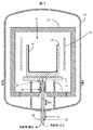
図1に示した結晶成長炉は、路殻(10)及び断熱材(12)によって包まれて規定されるホットゾーン(11)を含んでいる。ホットゾーン(11)内側に、少なくとも溶融する原料(示していない)、例えば、シリコン原料を含んでいる坩堝(14)が、台座(17)上の坩堝支持体(16)上に載っている坩堝支持体(16)の上にある坩堝ボックス(15)に収容されている。少なくとも側面発熱体(13)を坩堝(14)の周辺で用い、原料物質を溶融して、結晶性シリコンインゴットを製造する。更に、上部発熱体(示していない)も側面発熱体(13)と同時に用いて坩堝内の原料を溶融することができる。断熱材(12)は通常、示したように坩堝(14)上の上部断熱材、側面発熱体(13)と炉殻(10)の間の側面発熱剤及び底面断熱材を含んでいる。本発明の一実施態様では、上部、側面及び底面断熱材は、ホットゾーンから下の水冷した炉殻(10)へ熱を放出して、溶融した原料の再凝固を支援するために、坩堝(14)に関連して一緒に又は個々に移動できる。 The crystal growth furnace shown in FIG. 1 includes a hot zone (11) defined by being enclosed by a path shell (10) and a heat insulating material (12). A crucible in which a crucible (14) containing at least a raw material (not shown), for example, a silicon raw material, is placed on a crucible support (16) on a pedestal (17) inside the hot zone (11). It is housed in a crucible box (15) above the support (16). At least a side heating element (13) is used around the crucible (14), and the raw material is melted to produce a crystalline silicon ingot. Furthermore, the upper heating element (not shown) can be used simultaneously with the side heating element (13) to melt the raw material in the crucible. The insulation (12) typically includes an upper insulation on the crucible (14), a side heating agent between the side heating element (13) and the furnace shell (10) and a bottom insulation as shown. In one embodiment of the present invention, the top, side and bottom insulations are used to release heat from the hot zone to the lower water-cooled furnace shell (10) to assist in re-solidification of the molten feedstock ( Can be moved together or individually in connection with 14).
図1に示した結晶成長炉は更に、坩堝(14)の下中央に液冷式熱交換機(20)を含んでいて、これは矢印(20A)で示されるように垂直に移動可能である。液冷式熱交換機は互いに同軸の冷却液注管(21)及び冷却液排出管(22)を含んでいて、冷却剤注入管は、熱交換機バルブ(19)に封入されている冷却剤排出管の中にある。断熱被覆(18)が冷却剤注入管と冷却液排出管のホットゾーン(11)環境に曝されている部分を取り囲むことによって、原料の加熱及び溶融の間中に液冷式熱交換機をホットゾーンの下の奥寄りの位置に置くことができる。図1に示した実施態様では、液冷式熱交換機(20)は水平に移動できるので、熱除去バルブ(19)は、坩堝ボックス(15)と熱接触しているバルブを受け入れるような大きさ及び形態の坩堝支持体(16)の開口部を通って伸びている。接触すると、坩堝(14)から坩堝ボックス(15)を通って熱交換機バルブ(19)への熱経路が確立して、坩堝(14)と熱交換機バルブ(19)を互いに熱伝達状態にして熱交換機バルブ(19)が坩堝(14)の底から熱を除去できるようにする。 The crystal growth furnace shown in FIG. 1 further includes a liquid-cooled heat exchanger (20) in the lower center of the crucible (14), which is vertically movable as indicated by an arrow (20A). The liquid cooling type heat exchanger includes a coolant injection pipe (21) and a coolant discharge pipe (22) coaxial with each other, and the coolant injection pipe is a coolant discharge pipe enclosed in the heat exchanger valve (19). It is in. The heat insulation coating (18) surrounds the portions of the coolant injection pipe and the coolant discharge pipe that are exposed to the hot zone (11) environment, thereby allowing the liquid cooling heat exchanger to hot zone during the heating and melting of the raw materials. It can be placed in the back position below. In the embodiment shown in FIG. 1, the liquid-cooled heat exchanger (20) can be moved horizontally, so that the heat removal valve (19) is sized to receive a valve in thermal contact with the crucible box (15). And extending through an opening in the form of the crucible support (16). When contacted, a heat path from the crucible (14) through the crucible box (15) to the heat exchanger valve (19) is established, and the crucible (14) and the heat exchanger valve (19) are brought into a heat transfer state with each other. An exchange valve (19) allows heat to be removed from the bottom of the crucible (14).
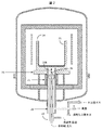
図2は、液冷式熱交換機(20)が坩堝(23)の下の封管外部ジャケット(29)内に包まれている本発明の別の実施態様を示す。ここで、封管外部ジャケット(29)は坩堝支持体(25)の開口部を通って坩堝(23)を含んでいる坩堝ボックス(24)内の部分開口部内へ伸びていて、断熱被覆(22)がジャケットの外側に用いられている。また、別の実施態様では、断熱被覆(22)を封管外部ジャケットの内部に用いることができる。本発明は、坩堝ボックス(24)と坩堝支持体(25)を、熱流を保持するために高い熱伝導度を有する高密度のグラファイトで作ることを目論んでいる。封管外部ジャケットを受け入れるために用いられる坩堝ボックス(24)と坩堝支持体(25)内の開口部の深さが本発明によって想定されている。図2に示したように、液冷式熱交換機(20)は矢印(22B)で示したように封管外部ジャケット内を垂直だけで移動する。封管外部ジャケット(29)の頂部まで完全に移動すると、熱除去バルブ(26)はジャケットの内部上面と接触して、坩堝(23)から坩堝ボックス(24)を通って熱交換機バルブ(26)への熱経路が確立して、坩堝(23)と熱交換機バルブ(26)を互いに熱伝導状態にして熱交換機バルブ(26)が溶融した原料を含んでいるるつぼ(23)の底から熱を、そこを通冷却液の流れに除去する。 FIG. 2 shows another embodiment of the present invention in which a liquid-cooled heat exchanger (20) is encased in a sealed outer jacket (29) under the crucible (23). Here, the sealed tube outer jacket (29) extends through the opening of the crucible support (25) into the partial opening in the crucible box (24) containing the crucible (23), and the heat insulating coating (22 ) Is used on the outside of the jacket. In another embodiment, a thermal barrier coating (22) can be used inside the sealed outer jacket. The present invention contemplates making the crucible box (24) and the crucible support (25) from high density graphite with high thermal conductivity to maintain heat flow. The depth of the opening in the crucible box (24) and crucible support (25) used to receive the sealed tube outer jacket is envisioned by the present invention. As shown in FIG. 2, the liquid-cooled heat exchanger (20) moves only vertically within the sealed outer jacket as shown by the arrow (22B). When fully moved to the top of the sealed outer jacket jacket (29), the heat removal valve (26) contacts the inner upper surface of the jacket and passes from the crucible (23) through the crucible box (24) to the heat exchanger valve (26). Heat path to the crucible (23), the heat exchanger valve (26) is in a heat conducting state with each other, heat is transferred from the bottom of the crucible (23) containing the molten material in the heat exchanger valve (26). , Through which it is removed into the flow of coolant.
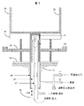
封管外部ジャケットのより詳細な描写を図2に示した本発明の実施態様の拡大図である図3に示し、ここでは液冷式熱交換機(36)が封管外部ジャケット(39)に包まれて、坩堝から熱を除去する位置までジャケット内を移動する。ジャケットは、炉内の環境を保持するために、従来のO−リング、ベローズシール又は当該技術分野で公知のその他の封印手段であってよい封印(31)で封印されている炉壁(30)を通り、ホットゾーン断熱材を通って、坩堝(33)を含んでいる坩堝ボックス(34)との熱接触へジャケットを受け入れる大きさ及び形態の坩堝支持体(35)の開口部内まで伸びている。示した実施態様では、断熱被覆(40)は封管外部ジャケット内部の冷却液注入管(37)及び冷却液排出管(38)を包んでいる。ここで、断熱皮膜は、ジャケットによって生じた奥よりのスペースの増大のために注入及び排出管上のより大きい表面積を物理的に覆うことができる。示したように、封管外部ジャケット(39)の坩堝末端は坩堝(33)の底と接触できず、むしろ、ジャケットの外部上面が坩堝ボックス(34)と直接熱接触する。しかし、液冷式熱交換機(36)が矢印(36A)で示したように上方に垂直移動すると、熱除去バルブ(41)は、坩堝ボックスと既に熱接触にある封管外部ジャケット(39)の上部の内部表面と熱接触して、熱経路を確立して熱除去バブル(41)を坩堝(33)と熱伝達状態にする。熱除去バルブ(41)が1つ又はそれ以上の熱伝導性中間構造、例えば、互いに熱接触している坩堝ボックス(34)及び/又は坩堝支持体(35)並びに坩堝(33)と熱伝達、好ましくは直接熱接触して、熱交換バルブ(41)が坩堝(33)と熱伝達可能な熱経路を確立する限り、液冷式熱交換機(36)を単独で、或いは封管外部ジャケット内に包んで用いて坩堝から熱を除去する別の実施態様も想定される。本発明は、坩堝がシャフトに対して移動不可能でシャフトが回転不可能な別の結晶成長炉形態での潜在的用途のために、封管外部ジャケットを液冷式熱交換機と共に水平移動可能な坩堝支持シャフトとして用いることも目論んでいる。 A more detailed depiction of the sealed outer jacket is shown in FIG. 3, which is an enlarged view of the embodiment of the present invention shown in FIG. 2, where the liquid-cooled heat exchanger (36) is wrapped in the sealed outer jacket (39). Rarely, it moves in the jacket to a position where heat is removed from the crucible. The jacket is sealed to the furnace wall (30) with a seal (31), which may be a conventional O-ring, bellows seal or other sealing means known in the art to maintain the environment within the furnace. Through the hot zone insulation and into the opening of the crucible support (35) sized and configured to receive the jacket into thermal contact with the crucible box (34) containing the crucible (33). . In the embodiment shown, the thermal barrier coating (40) encloses the coolant inlet tube (37) and coolant outlet tube (38) inside the sealed outer jacket. Here, the thermal barrier coating can physically cover the larger surface area on the inlet and outlet pipes due to the increased depth space created by the jacket. As shown, the crucible end of the sealed tube outer jacket (39) cannot contact the bottom of the crucible (33), rather the outer top surface of the jacket is in direct thermal contact with the crucible box (34). However, when the liquid-cooled heat exchanger (36) moves vertically upwards as indicated by the arrow (36A), the heat removal valve (41) is placed on the sealed outer jacket (39) already in thermal contact with the crucible box. In thermal contact with the upper internal surface, a heat path is established to place the heat removal bubble (41) in heat transfer with the crucible (33). Heat transfer with one or more thermally conductive intermediate structures, such as a crucible box (34) and / or a crucible support (35) and a crucible (33), in which the heat removal valve (41) is in thermal contact with each other; As long as the heat exchange valve (41) establishes a heat path that can transfer heat with the crucible (33), preferably in direct thermal contact, the liquid-cooled heat exchanger (36) alone or in a sealed outer jacket Other embodiments are also envisioned which are wrapped and used to remove heat from the crucible. The present invention allows the sealed outer jacket to move horizontally with a liquid-cooled heat exchanger for potential applications in other crystal growth furnace configurations where the crucible is not movable relative to the shaft and the shaft is not rotatable. It is also intended to be used as a crucible support shaft.
本発明は、これに限定されないが、シリコンを包含する溶解した原料から経済的にそして安全に様々な結晶物質を成長させる結晶成長炉で用いるための液冷式熱交換機に関する。この液冷式熱交換機は、水のような冷却液によって生ずる高い熱負荷能力を有する、銅のような高い熱伝導性物質で作られた熱除去バルブの、坩堝の下から熱を効果的に除去して結晶核形成及びインゴット成長を促進する望ましい特性を兼ね備えている。本発明の熱除去バルブは、高い熱伝導特性を有している、金属物質のような様々な種類の物質で作ることができる。表1は一般に知られている3つの最も高い熱伝導性金属を示し、銀が最も高い熱伝導率を保持し、銅及び金が続く。銅は、その高い熱伝導率及び銀及び金と比べて比較的低い価格のために望ましい。 The present invention relates to a liquid-cooled heat exchanger for use in a crystal growth furnace for economically and safely growing various crystal materials from a melted raw material including silicon, but is not limited thereto. This liquid-cooled heat exchanger effectively removes heat from the bottom of the crucible in a heat removal valve made of a highly heat conductive material such as copper, which has a high heat load capability caused by a coolant such as water. It has the desirable properties of removing and promoting crystal nucleation and ingot growth. The heat removal valve of the present invention can be made of various types of materials, such as metallic materials, which have high heat conduction characteristics. Table 1 shows the three highest heat conductive metals commonly known, with silver holding the highest heat conductivity, followed by copper and gold. Copper is desirable because of its high thermal conductivity and relatively low price compared to silver and gold.

シリコンのような、溶融原料を含んでいる坩堝から熱を効率的に除去するために、銅の熱除去バルブのような、約200W/(m・k)より大きい熱伝導度を有している物質で作られた熱除去バルブを、特にバルブが原料のそれより低い融点を有している場合に水のような冷却液と共に用いることが可能であることが意外にも見出された。例えば、銅の融点(約1085℃)はシリコンの溶融温度より約330℃低い。しかし、冷却剤としての水が循環している銅の熱除去バルブは効率的に熱を除去して損傷なしにシリコンインゴットの成長を促進することが見出された。銅の高い熱伝導特性は、銅の熱除去バルブを通って循環している水の高い熱負荷運搬能力と共に、その融点以上の表面と熱接触させたときあっても、銅の熱除去バルブの構造的完全性を保持する要因である高い熱除去効果をもたらすと考えられる。高い熱伝導性金属と冷却剤としての水との組み合わせが、銀の融点より約450℃高い溶融シリコンを含んでいる坩堝から熱を除去するために用いられる水冷銀熱除去バルブの構造的安定性を同様に保持すると期待されたときに、同様な熱除去効果が実現した。冷却液注入及びアウトラインラインが炉の内部を断熱するので、熱除去バルブにおいて冷却のみが生じると坩堝内で核形成、続いて結晶成長が始まる。内部の液漏れに起因する蒸気圧を排出するように設計された管外部ジャケットに包まれている場合、液冷式熱交換機は水のような冷却液によって冷却される熱除去バルブの高い熱伝導特性を生かす安全手段をさらに提供する。 In order to efficiently remove heat from a crucible containing a molten raw material, such as silicon, it has a thermal conductivity greater than about 200 W / (m · k), such as a copper heat removal valve. It has been surprisingly found that a heat removal valve made of material can be used with a coolant such as water, especially when the valve has a lower melting point than that of the raw material. For example, the melting point of copper (about 1085 ° C.) is about 330 ° C. lower than the melting temperature of silicon. However, it has been found that a copper heat removal valve with circulating water as a coolant efficiently removes heat and promotes silicon ingot growth without damage. The high heat transfer properties of copper, along with the high heat load carrying capacity of the water circulating through the copper heat removal valve, make it even more in contact with surfaces above its melting point. It is thought that the high heat removal effect which is a factor maintaining structural integrity is brought about. Structural stability of a water-cooled silver heat removal valve where a combination of a high thermal conductivity metal and water as a coolant is used to remove heat from a crucible containing molten silicon about 450 ° C. above the melting point of silver A similar heat removal effect was realized when expected to hold the same. Since the coolant injection and outline lines insulate the interior of the furnace, nucleation and subsequent crystal growth begin in the crucible when only cooling occurs in the heat removal valve. When encased in a tube outer jacket designed to exhaust the vapor pressure due to internal liquid leakage, the liquid-cooled heat exchanger is a high heat transfer of a heat removal valve that is cooled by a coolant such as water. It further provides safety measures that take advantage of the properties.
本発明は更に、坩堝から熱を除去して結晶インゴット成長を促進するために坩堝の下の液冷式熱交換機を用いる、上で詳細に説明した、結晶成長炉内で結晶性インゴットを製造する方法に関する。方法は、少なくとも原料を含んでいる坩堝を結晶成長炉内に置くこと、冷却液を液冷式熱交換機内に循環させること、坩堝内の少なくとも原料物質を加熱及び溶融すること、結晶性インゴットの成長を促進するために、液冷式熱交換機を坩堝との熱伝達内へ垂直移動させること、の工程を含んでいる。本発明が管外部ジャケットに包まれた液冷式熱交換機を用いる場合は、結晶性インゴットを製造する方法は、少なくとも原料を含んでいる坩堝を結晶成長炉内に置くこと、冷却液を液冷式熱交換機内に循環させること、封管外部ジャケットを空にして空にしたジャケットを不活性ガス、好ましくはアルゴンガスで5〜15psgiの圧力に埋め戻すこと、坩堝内の少なくとも原料物質を加熱及び溶融すること、結晶性インゴットの成長を促進するために、液冷式熱交換機を下方及び坩堝との熱伝達内へ垂直移動させること、の工程を含んでいる。 The present invention further uses a liquid-cooled heat exchanger under the crucible to remove heat from the crucible and promote crystal ingot growth, producing a crystalline ingot in a crystal growth furnace, as described in detail above. Regarding the method. The method includes placing a crucible containing at least a raw material in a crystal growth furnace, circulating a coolant in a liquid-cooled heat exchanger, heating and melting at least a raw material in the crucible, and forming a crystalline ingot In order to promote the growth, the liquid cooling heat exchanger is moved vertically into the heat transfer with the crucible. When the present invention uses a liquid-cooled heat exchanger wrapped in a tube outer jacket, a method for producing a crystalline ingot includes placing a crucible containing at least a raw material in a crystal growth furnace, and cooling the coolant by liquid cooling. Circulating in the heat exchanger, evacuating the sealed outer jacket and backfilling the emptied jacket with an inert gas, preferably argon gas, to a pressure of 5-15 psgi, heating at least the source material in the crucible and Melting and moving the liquid-cooled heat exchanger vertically and into heat transfer with the crucible to promote the growth of the crystalline ingot.
本発明の好ましい実施態様の前記記載は説明及び記述の目的で示されている。網羅的にすること、又は本発明を開示そのものに限定することを意図していない。修正及び改変は上記の教示を考慮すると可能であり、或いは本発明の実施から得ることができるだろう。実施態様は本発明の本質を説明するために選択され、記載されていて、当業者が多種実施態様及び各種修正を有する本発明を利用できるようにするその実際の適用は意図した特定の使用に適している。本発明の範囲は本明細書に添付されている特許請求の範囲、及びその均等物によって定義されていることが意図されている。 The foregoing description of preferred embodiments of the invention has been presented for purposes of illustration and description. It is not intended to be exhaustive or to limit the invention to the disclosure itself. Modifications and variations are possible in light of the above teachings or may be obtained from practice of the invention. While the embodiments have been chosen and described to illustrate the nature of the invention, its actual application to enable those skilled in the art to utilize the invention with various embodiments and various modifications is intended for the specific use intended. Is suitable. It is intended that the scope of the invention be defined by the claims appended hereto and their equivalents.
Claims (38)
約200W/(m・k)より大きい熱伝導度を有している物質で作られた熱除去バルブ;及び
冷却液注入管及び冷却液排出管(ここで、冷却液注入管、冷却液排出管、又はその両方は冷却液がそこを通って循環するように熱除去バルブに取り付けられている):を含んでいる:
坩堝の下を垂直に移動可能な液冷式熱交換機:を含んでいる、
結晶性インゴットを成長させる結晶成長炉。 A crucible containing at least the source material; and a heat removal valve made of a material having a thermal conductivity greater than about 200 W / (m · k); and a coolant inlet tube and a coolant outlet tube (where , A coolant inlet tube, a coolant outlet tube, or both are attached to the heat removal valve so that the coolant circulates therethrough):
A liquid-cooled heat exchanger that can be moved vertically under the crucible.
A crystal growth furnace for growing crystalline ingots.
坩堝の下を垂直に移動可能な液冷式熱交換機の中に冷却液を循環させること(ここで、液冷式熱交換機は、約200W/(m・k)より大きい熱伝導度を有している物質で作られた熱除去バルブ、冷却液注入管及び冷却液排出管(ここで、冷却液注入管、冷却液排出管、又はその両方は、冷却液がその中を循環するように熱除去バルブに取り付けられている)を含んでいる);
坩堝内の少なくとも原料物質を加熱及び溶融すること;及び
結晶性インゴットの成長を促進するために、液冷式熱交換機を坩堝との熱伝達内へ垂直に移動すること:
の工程を含んでいる、結晶成長炉で結晶性インゴットを製造する方法。 Placing a crucible containing at least the raw material in a crystal growth furnace;
Circulating coolant in a liquid-cooled heat exchanger that can move vertically under the crucible (where the liquid-cooled heat exchanger has a thermal conductivity greater than about 200 W / (m · k) A heat removal valve, a coolant injection tube and a coolant discharge tube (where the coolant injection tube, the coolant discharge tube, or both are made of heat so that the coolant circulates in them. Attached to the removal valve));
Heating and melting at least the source material in the crucible; and moving the liquid-cooled heat exchanger vertically into the heat transfer with the crucible to promote the growth of the crystalline ingot:
A method for producing a crystalline ingot in a crystal growth furnace, comprising the steps of:
Applications Claiming Priority (3)
| Application Number | Priority Date | Filing Date | Title |
|---|---|---|---|
| US201161514019P | 2011-08-01 | 2011-08-01 | |
| US61/514,019 | 2011-08-01 | ||
| PCT/US2012/047061 WO2013019401A1 (en) | 2011-08-01 | 2012-07-17 | Liquid-cooled heat exchanger |
Related Child Applications (1)
| Application Number | Title | Priority Date | Filing Date |
|---|---|---|---|
| JP2017062206A Division JP2017149641A (en) | 2011-08-01 | 2017-03-28 | Liquid-cooled heat exchanger |
Publications (2)
| Publication Number | Publication Date |
|---|---|
| JP2014527013A true JP2014527013A (en) | 2014-10-09 |
| JP2014527013A5 JP2014527013A5 (en) | 2015-08-27 |
Family
ID=47629587
Family Applications (2)
| Application Number | Title | Priority Date | Filing Date |
|---|---|---|---|
| JP2014523949A Pending JP2014527013A (en) | 2011-08-01 | 2012-07-17 | Liquid-cooled heat exchanger |
| JP2017062206A Pending JP2017149641A (en) | 2011-08-01 | 2017-03-28 | Liquid-cooled heat exchanger |
Family Applications After (1)
| Application Number | Title | Priority Date | Filing Date |
|---|---|---|---|
| JP2017062206A Pending JP2017149641A (en) | 2011-08-01 | 2017-03-28 | Liquid-cooled heat exchanger |
Country Status (7)
| Country | Link |
|---|---|
| US (1) | US9982361B2 (en) |
| EP (1) | EP2739771A4 (en) |
| JP (2) | JP2014527013A (en) |
| KR (1) | KR20140057305A (en) |
| CN (1) | CN103890242B (en) |
| RU (1) | RU2560439C1 (en) |
| WO (1) | WO2013019401A1 (en) |
Families Citing this family (9)
| Publication number | Priority date | Publication date | Assignee | Title |
|---|---|---|---|---|
| US9139931B2 (en) * | 2011-05-11 | 2015-09-22 | Memc Singapore Pte. Ltd. | Directional solidification furnace heat exchanger |
| US20150090181A1 (en) * | 2013-09-30 | 2015-04-02 | Gt Crystal Systems, Llc | Automated heat exchanger alignment |
| GB201319671D0 (en) | 2013-11-07 | 2013-12-25 | Ebner Ind Ofenbau | Controlling a temperature of a crucible inside an oven |
| CN104792169A (en) * | 2015-04-29 | 2015-07-22 | 浙江天源炉业科技有限公司 | Heating furnace |
| CN105586635B (en) * | 2016-01-20 | 2018-07-17 | 西安交通大学 | A kind of device and method that ingot casting quickly solidifies |
| KR102611508B1 (en) | 2018-06-27 | 2023-12-08 | 엘지전자 주식회사 | Vacuum adiabatic body and refrigerator |
| IT201900000235A1 (en) * | 2019-01-09 | 2020-07-09 | Lpe Spa | Reaction chamber for a deposition reactor with cavity and bottom sealing element and reactor |
| CN112725645A (en) * | 2020-12-22 | 2021-04-30 | 大冶市兴进铝业有限公司 | Novel aluminium alloy preparation device |
| CN115029771A (en) * | 2022-07-13 | 2022-09-09 | 北京铭镓半导体有限公司 | Crucible adhesion preventing method for color gem crystal growth crucible by VGF method |
Citations (5)
| Publication number | Priority date | Publication date | Assignee | Title |
|---|---|---|---|---|
| JPS63166711A (en) * | 1986-12-26 | 1988-07-09 | Osaka Titanium Seizo Kk | Production of polycrystalline silicon ingot |
| JPH11292696A (en) * | 1998-04-15 | 1999-10-26 | Nikon Corp | Fluorite production unit |
| WO2005092791A1 (en) * | 2004-03-29 | 2005-10-06 | Kyocera Corporation | Silicon casting device and multicrystal silicon ingot producing method |
| JP2009018987A (en) * | 2007-07-10 | 2009-01-29 | Commissariat A L'energie Atomique | Apparatus for manufacturing crystalline material block by adjusting heat conductivity |
| WO2010005705A1 (en) * | 2008-06-16 | 2010-01-14 | Gt Solar Incorporated | Systems and methods for growing monocrystalline silicon ingots by directional solidification |
Family Cites Families (13)
| Publication number | Priority date | Publication date | Assignee | Title |
|---|---|---|---|---|
| US5135047A (en) | 1989-10-05 | 1992-08-04 | Flavio Dobran | Furnace for high quality and superconducting bulk crystal growths |
| JPH06345585A (en) * | 1993-06-14 | 1994-12-20 | Sumitomo Metal Ind Ltd | Method for pulling up single crystal |
| JP3388664B2 (en) | 1995-12-28 | 2003-03-24 | シャープ株式会社 | Method and apparatus for manufacturing polycrystalline semiconductor |
| JPH09255484A (en) * | 1996-03-26 | 1997-09-30 | Sumitomo Sitix Corp | Supporting member for crucible for pulling single crystal |
| JP3520957B2 (en) * | 1997-06-23 | 2004-04-19 | シャープ株式会社 | Method and apparatus for manufacturing polycrystalline semiconductor ingot |
| JPH11310496A (en) * | 1998-02-25 | 1999-11-09 | Mitsubishi Materials Corp | Production of silicon ingot having unidirectionally solidified texture and apparatus therefor |
| FR2853913B1 (en) * | 2003-04-17 | 2006-09-29 | Apollon Solar | CUTTER FOR A DEVICE FOR MANUFACTURING A BLOCK OF CRYSTALLINE MATERIAL AND METHOD OF MANUFACTURE |
| JP2005015264A (en) * | 2003-06-25 | 2005-01-20 | Canon Inc | Apparatus and method for manufacturing crystal |
| WO2005003413A1 (en) * | 2003-07-03 | 2005-01-13 | Hitachi Chemical Co., Ltd. | Crucible and method of growing single crystal by using crucible |
| JP2007332022A (en) | 2006-06-13 | 2007-12-27 | Young Sang Cho | Apparatus for producing polycrystalline silicon ingot |
| KR100955221B1 (en) | 2007-10-05 | 2010-04-29 | 주식회사 글로실 | Apparatus for manufacturing poly crystaline silicon ingot for solar battery having door open/close device using hinge |
| KR100947836B1 (en) * | 2009-09-28 | 2010-03-18 | (주)세미머티리얼즈 | Apparatus for manufacturing silicon ingot |
| IT1396761B1 (en) | 2009-10-21 | 2012-12-14 | Saet Spa | METHOD AND DEVICE FOR OBTAINING A MULTI-CRYSTALLINE SEMICONDUCTOR MATERIAL, IN PARTICULAR SILICON |
-
2012
- 2012-07-17 CN CN201280048372.0A patent/CN103890242B/en not_active Expired - Fee Related
- 2012-07-17 WO PCT/US2012/047061 patent/WO2013019401A1/en active Application Filing
- 2012-07-17 RU RU2014107850/05A patent/RU2560439C1/en not_active IP Right Cessation
- 2012-07-17 KR KR1020147005409A patent/KR20140057305A/en not_active Application Discontinuation
- 2012-07-17 US US14/348,792 patent/US9982361B2/en active Active
- 2012-07-17 EP EP12820600.0A patent/EP2739771A4/en not_active Withdrawn
- 2012-07-17 JP JP2014523949A patent/JP2014527013A/en active Pending
-
2017
- 2017-03-28 JP JP2017062206A patent/JP2017149641A/en active Pending
Patent Citations (5)
| Publication number | Priority date | Publication date | Assignee | Title |
|---|---|---|---|---|
| JPS63166711A (en) * | 1986-12-26 | 1988-07-09 | Osaka Titanium Seizo Kk | Production of polycrystalline silicon ingot |
| JPH11292696A (en) * | 1998-04-15 | 1999-10-26 | Nikon Corp | Fluorite production unit |
| WO2005092791A1 (en) * | 2004-03-29 | 2005-10-06 | Kyocera Corporation | Silicon casting device and multicrystal silicon ingot producing method |
| JP2009018987A (en) * | 2007-07-10 | 2009-01-29 | Commissariat A L'energie Atomique | Apparatus for manufacturing crystalline material block by adjusting heat conductivity |
| WO2010005705A1 (en) * | 2008-06-16 | 2010-01-14 | Gt Solar Incorporated | Systems and methods for growing monocrystalline silicon ingots by directional solidification |
Also Published As
| Publication number | Publication date |
|---|---|
| RU2560439C1 (en) | 2015-08-20 |
| KR20140057305A (en) | 2014-05-12 |
| EP2739771A4 (en) | 2014-11-19 |
| CN103890242B (en) | 2018-05-08 |
| US9982361B2 (en) | 2018-05-29 |
| WO2013019401A1 (en) | 2013-02-07 |
| CN103890242A (en) | 2014-06-25 |
| US20160130721A1 (en) | 2016-05-12 |
| EP2739771A1 (en) | 2014-06-11 |
| JP2017149641A (en) | 2017-08-31 |
Similar Documents
| Publication | Publication Date | Title |
|---|---|---|
| JP2017149641A (en) | Liquid-cooled heat exchanger | |
| JP5344919B2 (en) | Apparatus and method for crystal growth | |
| JP5380442B2 (en) | Method and apparatus for producing cast silicon from seed crystals | |
| JPWO2005092791A1 (en) | Silicon casting apparatus and method for manufacturing polycrystalline silicon ingot | |
| EP2640874B1 (en) | Apparatus and method for directional solidification of silicon | |
| CN202989330U (en) | Novel polycrystalline furnace heating device | |
| US20150086464A1 (en) | Method of producing monocrystalline silicon | |
| US20130219967A1 (en) | Method and device for producing polycrystalline silicon blocks | |
| TWI547603B (en) | Apparatus and method for producing a multicrystalline material having large grain sizes | |
| WO2009118993A1 (en) | Single crystal manufacturing apparatus and single crystal manufacturing method | |
| JP4815003B2 (en) | Crucible for silicon crystal growth, crucible manufacturing method for silicon crystal growth, and silicon crystal growth method | |
| JP2014527013A5 (en) | ||
| KR20150023058A (en) | Controlled directional solidification of silicon | |
| JPS646130B2 (en) | ||
| US20150093231A1 (en) | Advanced crucible support and thermal distribution management | |
| JP2008222481A (en) | Manufacturing method and device of compound semiconductor | |
| CN102912416A (en) | Novel polycrystalline furnace heating device | |
| JP5057770B2 (en) | Method for producing solid phase sheet | |
| WO2011104795A1 (en) | 多結晶シリコンウェーハpolycrystalline silicon wafer | |
| KR20120000199A (en) | Apparatus for growing single crystal ingot | |
| WO2013019399A2 (en) | Method for producing a monocrystalline product | |
| JP2013056812A (en) | Method for producing polycrystalline silicon ingot | |
| TW201435160A (en) | Manufacturing device for polycrystalline silicon ingot and method of manufacturing the same | |
| JPS6138160B2 (en) |
Legal Events
| Date | Code | Title | Description |
|---|---|---|---|
| A521 | Written amendment |
Free format text: JAPANESE INTERMEDIATE CODE: A523 Effective date: 20150708 |
|
| A621 | Written request for application examination |
Free format text: JAPANESE INTERMEDIATE CODE: A621 Effective date: 20150708 |
|
| A977 | Report on retrieval |
Free format text: JAPANESE INTERMEDIATE CODE: A971007 Effective date: 20160129 |
|
| A131 | Notification of reasons for refusal |
Free format text: JAPANESE INTERMEDIATE CODE: A131 Effective date: 20160217 |
|
| A601 | Written request for extension of time |
Free format text: JAPANESE INTERMEDIATE CODE: A601 Effective date: 20160513 |
|
| A521 | Written amendment |
Free format text: JAPANESE INTERMEDIATE CODE: A523 Effective date: 20160715 |
|
| A02 | Decision of refusal |
Free format text: JAPANESE INTERMEDIATE CODE: A02 Effective date: 20161128 |