JP2014521893A - A moving assembly comprising a starter drive unit and a control lever for meshing with a starter ring gear of a heat engine, and a heat engine starter comprising such an assembly - Google Patents
A moving assembly comprising a starter drive unit and a control lever for meshing with a starter ring gear of a heat engine, and a heat engine starter comprising such an assembly Download PDFInfo
- Publication number
- JP2014521893A JP2014521893A JP2014522140A JP2014522140A JP2014521893A JP 2014521893 A JP2014521893 A JP 2014521893A JP 2014522140 A JP2014522140 A JP 2014522140A JP 2014522140 A JP2014522140 A JP 2014522140A JP 2014521893 A JP2014521893 A JP 2014521893A
- Authority
- JP
- Japan
- Prior art keywords
- starter
- lever
- drive element
- assembly according
- casing
- Prior art date
- Legal status (The legal status is an assumption and is not a legal conclusion. Google has not performed a legal analysis and makes no representation as to the accuracy of the status listed.)
- Pending
Links
- 239000007858 starting material Substances 0.000 title claims abstract description 169
- 238000006243 chemical reaction Methods 0.000 claims abstract description 107
- 230000033001 locomotion Effects 0.000 claims description 21
- 230000003111 delayed effect Effects 0.000 claims description 6
- 239000002243 precursor Substances 0.000 claims 1
- 239000000463 material Substances 0.000 description 26
- 230000004048 modification Effects 0.000 description 21
- 238000012986 modification Methods 0.000 description 21
- 230000009467 reduction Effects 0.000 description 19
- 229910052751 metal Inorganic materials 0.000 description 18
- 239000002184 metal Substances 0.000 description 18
- 239000004033 plastic Substances 0.000 description 13
- 229920003023 plastic Polymers 0.000 description 13
- 230000006870 function Effects 0.000 description 10
- 230000005540 biological transmission Effects 0.000 description 8
- 230000002829 reductive effect Effects 0.000 description 7
- 230000002093 peripheral effect Effects 0.000 description 5
- 238000003825 pressing Methods 0.000 description 5
- XEEYBQQBJWHFJM-UHFFFAOYSA-N Iron Chemical compound [Fe] XEEYBQQBJWHFJM-UHFFFAOYSA-N 0.000 description 4
- 238000003466 welding Methods 0.000 description 4
- 230000005291 magnetic effect Effects 0.000 description 3
- 238000000465 moulding Methods 0.000 description 3
- 230000002441 reversible effect Effects 0.000 description 3
- 230000035939 shock Effects 0.000 description 3
- 238000005245 sintering Methods 0.000 description 3
- 229910001018 Cast iron Inorganic materials 0.000 description 2
- RYGMFSIKBFXOCR-UHFFFAOYSA-N Copper Chemical compound [Cu] RYGMFSIKBFXOCR-UHFFFAOYSA-N 0.000 description 2
- VYPSYNLAJGMNEJ-UHFFFAOYSA-N Silicium dioxide Chemical compound O=[Si]=O VYPSYNLAJGMNEJ-UHFFFAOYSA-N 0.000 description 2
- 230000001133 acceleration Effects 0.000 description 2
- 238000013459 approach Methods 0.000 description 2
- 230000008859 change Effects 0.000 description 2
- 230000006835 compression Effects 0.000 description 2
- 238000007906 compression Methods 0.000 description 2
- 229910052802 copper Inorganic materials 0.000 description 2
- 239000010949 copper Substances 0.000 description 2
- 230000008878 coupling Effects 0.000 description 2
- 238000010168 coupling process Methods 0.000 description 2
- 238000005859 coupling reaction Methods 0.000 description 2
- 238000002788 crimping Methods 0.000 description 2
- 230000007423 decrease Effects 0.000 description 2
- 239000000835 fiber Substances 0.000 description 2
- 239000000446 fuel Substances 0.000 description 2
- 230000006698 induction Effects 0.000 description 2
- 230000036961 partial effect Effects 0.000 description 2
- 239000000843 powder Substances 0.000 description 2
- OKTJSMMVPCPJKN-UHFFFAOYSA-N Carbon Chemical compound [C] OKTJSMMVPCPJKN-UHFFFAOYSA-N 0.000 description 1
- 229910000881 Cu alloy Inorganic materials 0.000 description 1
- 229910000640 Fe alloy Inorganic materials 0.000 description 1
- 229920002430 Fibre-reinforced plastic Polymers 0.000 description 1
- 208000003618 Intervertebral Disc Displacement Diseases 0.000 description 1
- 229920000271 Kevlar® Polymers 0.000 description 1
- 229910000831 Steel Inorganic materials 0.000 description 1
- 230000002159 abnormal effect Effects 0.000 description 1
- 230000009471 action Effects 0.000 description 1
- 238000004026 adhesive bonding Methods 0.000 description 1
- 229910052782 aluminium Inorganic materials 0.000 description 1
- XAGFODPZIPBFFR-UHFFFAOYSA-N aluminium Chemical compound [Al] XAGFODPZIPBFFR-UHFFFAOYSA-N 0.000 description 1
- 239000004760 aramid Substances 0.000 description 1
- 229920006231 aramid fiber Polymers 0.000 description 1
- 238000005452 bending Methods 0.000 description 1
- 230000008901 benefit Effects 0.000 description 1
- 239000011230 binding agent Substances 0.000 description 1
- 230000015572 biosynthetic process Effects 0.000 description 1
- 238000002485 combustion reaction Methods 0.000 description 1
- 230000000295 complement effect Effects 0.000 description 1
- 230000006378 damage Effects 0.000 description 1
- 230000006837 decompression Effects 0.000 description 1
- 230000000694 effects Effects 0.000 description 1
- 239000012777 electrically insulating material Substances 0.000 description 1
- 230000008030 elimination Effects 0.000 description 1
- 238000003379 elimination reaction Methods 0.000 description 1
- 238000004880 explosion Methods 0.000 description 1
- 239000003302 ferromagnetic material Substances 0.000 description 1
- 239000011151 fibre-reinforced plastic Substances 0.000 description 1
- 229910002804 graphite Inorganic materials 0.000 description 1
- 239000010439 graphite Substances 0.000 description 1
- 238000009499 grossing Methods 0.000 description 1
- 238000010438 heat treatment Methods 0.000 description 1
- 230000003993 interaction Effects 0.000 description 1
- 229910052742 iron Inorganic materials 0.000 description 1
- 230000008407 joint function Effects 0.000 description 1
- 239000004761 kevlar Substances 0.000 description 1
- 230000000670 limiting effect Effects 0.000 description 1
- 238000003754 machining Methods 0.000 description 1
- 230000013011 mating Effects 0.000 description 1
- 230000007246 mechanism Effects 0.000 description 1
- 230000002028 premature Effects 0.000 description 1
- 230000002035 prolonged effect Effects 0.000 description 1
- 239000011347 resin Substances 0.000 description 1
- 229920005989 resin Polymers 0.000 description 1
- 230000004044 response Effects 0.000 description 1
- 230000000284 resting effect Effects 0.000 description 1
- 230000000979 retarding effect Effects 0.000 description 1
- 239000000377 silicon dioxide Substances 0.000 description 1
- 239000010959 steel Substances 0.000 description 1
- 229920001187 thermosetting polymer Polymers 0.000 description 1
- 230000007704 transition Effects 0.000 description 1
- 230000001960 triggered effect Effects 0.000 description 1
- 238000001845 vibrational spectrum Methods 0.000 description 1
- 238000004804 winding Methods 0.000 description 1
Images


Classifications
-
- F—MECHANICAL ENGINEERING; LIGHTING; HEATING; WEAPONS; BLASTING
- F02—COMBUSTION ENGINES; HOT-GAS OR COMBUSTION-PRODUCT ENGINE PLANTS
- F02N—STARTING OF COMBUSTION ENGINES; STARTING AIDS FOR SUCH ENGINES, NOT OTHERWISE PROVIDED FOR
- F02N15/00—Other power-operated starting apparatus; Component parts, details, or accessories, not provided for in, or of interest apart from groups F02N5/00 - F02N13/00
- F02N15/02—Gearing between starting-engines and started engines; Engagement or disengagement thereof
- F02N15/08—Gearing between starting-engines and started engines; Engagement or disengagement thereof the gearing being of friction type
-
- F—MECHANICAL ENGINEERING; LIGHTING; HEATING; WEAPONS; BLASTING
- F02—COMBUSTION ENGINES; HOT-GAS OR COMBUSTION-PRODUCT ENGINE PLANTS
- F02N—STARTING OF COMBUSTION ENGINES; STARTING AIDS FOR SUCH ENGINES, NOT OTHERWISE PROVIDED FOR
- F02N15/00—Other power-operated starting apparatus; Component parts, details, or accessories, not provided for in, or of interest apart from groups F02N5/00 - F02N13/00
- F02N15/02—Gearing between starting-engines and started engines; Engagement or disengagement thereof
- F02N15/022—Gearing between starting-engines and started engines; Engagement or disengagement thereof the starter comprising an intermediate clutch
- F02N15/025—Gearing between starting-engines and started engines; Engagement or disengagement thereof the starter comprising an intermediate clutch of the friction type
-
- F—MECHANICAL ENGINEERING; LIGHTING; HEATING; WEAPONS; BLASTING
- F02—COMBUSTION ENGINES; HOT-GAS OR COMBUSTION-PRODUCT ENGINE PLANTS
- F02N—STARTING OF COMBUSTION ENGINES; STARTING AIDS FOR SUCH ENGINES, NOT OTHERWISE PROVIDED FOR
- F02N15/00—Other power-operated starting apparatus; Component parts, details, or accessories, not provided for in, or of interest apart from groups F02N5/00 - F02N13/00
- F02N15/02—Gearing between starting-engines and started engines; Engagement or disengagement thereof
- F02N15/04—Gearing between starting-engines and started engines; Engagement or disengagement thereof the gearing including disengaging toothed gears
- F02N15/06—Gearing between starting-engines and started engines; Engagement or disengagement thereof the gearing including disengaging toothed gears the toothed gears being moved by axial displacement
- F02N15/067—Gearing between starting-engines and started engines; Engagement or disengagement thereof the gearing including disengaging toothed gears the toothed gears being moved by axial displacement the starter comprising an electro-magnetically actuated lever
-
- F—MECHANICAL ENGINEERING; LIGHTING; HEATING; WEAPONS; BLASTING
- F02—COMBUSTION ENGINES; HOT-GAS OR COMBUSTION-PRODUCT ENGINE PLANTS
- F02N—STARTING OF COMBUSTION ENGINES; STARTING AIDS FOR SUCH ENGINES, NOT OTHERWISE PROVIDED FOR
- F02N11/00—Starting of engines by means of electric motors
-
- F—MECHANICAL ENGINEERING; LIGHTING; HEATING; WEAPONS; BLASTING
- F02—COMBUSTION ENGINES; HOT-GAS OR COMBUSTION-PRODUCT ENGINE PLANTS
- F02N—STARTING OF COMBUSTION ENGINES; STARTING AIDS FOR SUCH ENGINES, NOT OTHERWISE PROVIDED FOR
- F02N11/00—Starting of engines by means of electric motors
- F02N11/08—Circuits or control means specially adapted for starting of engines
- F02N11/0851—Circuits or control means specially adapted for starting of engines characterised by means for controlling the engagement or disengagement between engine and starter, e.g. meshing of pinion and engine gear
- F02N11/0855—Circuits or control means specially adapted for starting of engines characterised by means for controlling the engagement or disengagement between engine and starter, e.g. meshing of pinion and engine gear during engine shutdown or after engine stop before start command, e.g. pre-engagement of pinion
Landscapes
- Engineering & Computer Science (AREA)
- Chemical & Material Sciences (AREA)
- Combustion & Propulsion (AREA)
- Mechanical Engineering (AREA)
- General Engineering & Computer Science (AREA)
- Mechanical Operated Clutches (AREA)
- Connection Of Motors, Electrical Generators, Mechanical Devices, And The Like (AREA)
Abstract
ヒートエンジンの歯付きスターターリングギア(C)と噛み合うための移動アセンブリ(500)は、ピニオン(11)が設けられる駆動ユニット(1)と、スターター駆動要素(118)と、2つのアームを有するフォーク状の下端を含む回動制御レバー(20)と、摩擦クラッチ(300)とを備え、前記ピニオンは、駆動要素(118)を部分的に収容するケーシングと回転可能に固定されるとともに、クラッチの反作用プレート(112)を備える。レバー(20)は、クラッチを閉じるための手段と関連付けられるとともに、ケーシングを軸方向に移動させるように構成され、一方、クラッチを閉じるための前記手段は、摩擦クラッチを締め付けるために駆動要素を軸方向に移動させるように構成される。ヒートエンジンスターターはそのような移動アセンブリを備える。 A moving assembly (500) for meshing with a toothed starter ring gear (C) of a heat engine comprises a drive unit (1) provided with a pinion (11), a starter drive element (118), and a fork having two arms And a friction clutch (300). The pinion is rotatably fixed to a casing partially containing the drive element (118), and the clutch A reaction plate (112) is provided. The lever (20) is associated with means for closing the clutch and is configured to move the casing axially, while said means for closing the clutch pivots the drive element to tighten the friction clutch. Configured to move in the direction. The heat engine starter comprises such a moving assembly.
Description
この発明は、ヒートエンジンの、特に自動車のヒートエンジンのスターターリングギアと噛み合うための移動スターター駆動ユニット・制御レバーアセンブリに関する。 The present invention relates to a moving starter drive unit and control lever assembly for meshing with a starter ring gear of a heat engine, in particular an automobile heat engine.
また、この発明は、そのようなアセンブリを組み込むヒートエンジンの、特に自動車のヒートエンジンのためのスターターに関する。 The invention also relates to a starter for a heat engine, in particular an automotive heat engine, incorporating such an assembly.
仏国特許第2787833号明細書の図1の軸方向断面図に類似する軸方向断面図である図1に見られるように、ヒートエンジン、特に自動車エンジンのための従来のスターター4は、
−ケーシング18と、
−ケーシング18により回転駆動される出力シャフト24と、
−出力シャフト24に移動可能に装着されるスターター駆動ユニット1と、
−スターター駆動ユニット1と共に移動アセンブリを形成し、スターター駆動ユニット1の動作を制御してスターター駆動ユニット1をヒートエンジンのスターターリングギアCと噛み合わせるように構成される制御レバー20と、
−ケーシング18内に収容され、スターター駆動ユニット1を駆動させるシャフト26が取り付けられる電気モータMと、
−制御レバーを操作するための手段と、
を備える。
As seen in FIG. 1, which is an axial cross-sectional view similar to the axial cross-sectional view of FIG. 1 of French Patent No. 2787833, a conventional starter 4 for a heat engine, in particular an automobile engine,
The
An
A
A
An electric motor M housed in the
-Means for operating the control lever;
Is provided.
操作手段は、スターター駆動ユニット1を移動させるために制御レバー20に作用して該制御レバーを回動させるように構成される移動コア部材2bを備えてもよい(図1参照)。
The operating means may include a moving
この移動コア部材2bは、ケーシング18によって支持される本体2dと移動制御ロッド3/移動接点3aアセンブリとを備える電磁コンタクタ2に属してもよく、この移動コア部材2bは、電力を電気モータMへ供給するために移動アセンブリに作用して該移動アセンブリを固定電気接点端子3e,3fのヘッドの方向で後方に移動させるように構成される。
This moving
スターターリングギアCは、仏国特許第2631094号明細書および英国特許第225757号明細書の場合と同様に、ヒートエンジンのクランクシャフトに強固に或いは弾性的に接続されるプレートと一体を成す外歯リング(図1)を備えてもよい。変形例として、駆動スターターリングCは、ベルト駆動伝動装置の一部を形成するプーリと一体を成す内歯リングギアを備えてもよく、前記ベルト駆動伝動装置は、前記プーリと、仏国特許第2858366号明細書に記載されるようなクランクシャフトと一体を成すプーリとの間で作用する。 The starter ring gear C is an external tooth integrally formed with a plate that is firmly or elastically connected to the crankshaft of the heat engine, as in French Patent Nos. 2631094 and British Patent No. 225757. A ring (FIG. 1) may be provided. As a variant, the drive starter ring C may comprise an internal ring gear that is integral with a pulley that forms part of the belt drive transmission device, the belt drive transmission device comprising: Acts between a crankshaft and integral pulley as described in US Pat. No. 2,858,366.
スターター4の出力シャフト24は、例えば英国特許第225757号明細書に記載される電気モータMの駆動シャフト26と組み合わされても、或いはシャフト26と別個であってもよく、また、仏国特許第2631094号明細書および仏国特許第2858366号明細書に記載される少なくとも1つの減速ギア34はシャフト24,26間に配置されている。
The
減速ギア34は、所定の出力においてスターターのサイズおよび重量を減少させつつ、より高速の電気モータを使用できるようにするとともに、より高い開始トルクを得ることができるようにする。これらの減速ギア34は、しばしば、シャフト24,26が同軸である(図1参照)遊星歯車トレインを有する減速ギアトレイン、または、シャフト24,26が互いに対して径方向にオフセットされる仏国特許第2631094号明細書に記載されるように内側にギアが付いた減速ギアトレインのいずれかである。
The
ここでは金属製であるケーシング18は、出力シャフト24の前端を回転装着するとともに車両の主要部に接続される車両の固定部にスターターを取り付けるように構成される前側ベアリングと、駆動シャフト26の後端を回転装着するように構成される後側ベアリングと、ベアリング間に挟まれる中間円柱ブロックとを備える。
The
図1の前側ベアリングは、電気モータMに電力が供給されるときにスターター1によって回転駆動されるようになっているスターターリングギアCの通過のための開口を下端に有する。前側ベアリングの上端は、ここではインダクタステータ30を備える電気モータMの上側に位置するコンタクタ2の本体2dを支持し、インダクタステータ30は、駆動シャフト26と一体を成す誘導ロータ14を取り囲むとともに、少なくとも一対のブラシ(参照符号を付さない)に擦るように接触する導電セグメントを有する整流子(参照符号を付さない)を後部に備える。
The front bearing in FIG. 1 has an opening at the lower end for passage of a starter ring gear C that is rotationally driven by the
ここでは、整流子は前面タイプであり、また、ブラシはシャフト24,26のX軸に対して軸方向に向けられる。
Here, the commutator is of the front type, and the brush is oriented in the axial direction with respect to the X axis of the
変形例として、仏国特許第2858366号明細書の場合のように、整流子が軸方向に向けられてもよく、また、ブラシがX軸に対して径方向に向けられてもよい。 As a modification, the commutator may be oriented in the axial direction and the brush may be oriented in the radial direction with respect to the X-axis, as in French Patent No. 2858366.
ケーシングブロック18は、永久磁石を備える、或いは変形例として、例えばEP 0749 194に記載されるタイプの誘導コイルを備える、ステータ30を内部で支持する。
The
ロータ14は、コイルを装着するための切り欠きを備えるシートのパッケージの形態を成す本体を備え、コイルの端部は整流子の導電セグメントに接続される。ブラシのうちの1つはアースに接続され、他のブラシは、後述する態様で車両バッテリーのプラス端子に接続される。好適には、ブラシの摩耗を減らすために、対のブラシが幾つか設けられる。
The
駆動シャフト26は、ここでは、その前端に、ジャーナル軸受を間に介するとともに軸方向楔球を伴って出力シャフト24の後端の止まり穴内に係合する平滑部によって延ばされる減速ギア34の太陽ピニオンを有する。減速ギア34の遊星キャリアは、ここでは、出力シャフト24の後端に強固に圧着され、一方、減速ギア34の硬質プラスチック材料から成るリングは、オーバーモールド成形によって、ベースプレートとして知られる金属プレート55と一体を成す。ノイズを減らすために好適にはプラスチック材料から成る制御レバー20は、プレート55上にオーバーモールドされる硬質プラスチック材料製の支持部上の中間点において連結態様で装着される。このプレート55は、コンタクタ2の本体2dのための支持部としての役目を果たす。この本体2dは、ケーシング18の前側ベアリングとブロックとの間にあるプレート55の上部の円形穴内に入れ子にされる。ここで、プレート55、コンタクタ2、および、ケーシング18の前側ベアリングのブロックは、ボルト56によって取り付けられる。更なる情報に関しては、仏国特許第2725758号明細書を参照されたい。
The
変形例として、減速ギア34は、仏国特許第2787833号明細書の図2〜図5に記載されるタイプのものであってもよい。この減速ギアは、異なる性質を有してもよく、特に、仏国特許第2631094号明細書の場合のようなトルクリミッタを組み込んでもよい。
As a modification, the
コンタクタ2は、強磁性材料からなる部分、すなわち、移動コア部材2bと、固定コア部材2fと、環状絶縁支持部2c上に装着される少なくとも1つのコイル2aが内部に設けられる本体2dとを有する。本体2dは、ここでは本体2dに圧着される電気絶縁材料製のキャップ2eによって後部が閉塞される。また、このキャップ2eは、キャップ2eの肩部と本体2dとの間で軸方向に楔留めされる固定コア体2fを固定するためにも使用される。キャップ2eには、キャップ2eの回転を阻止してキャップ2eを角度的に割り出すために固定コア部材2fの溝と係合する軸方向突起が設けられる。支持部2cは、固定コア部材2fのための環状支持部(参照符号を付さない)と係合する。この支持部2cと本体2dの前端とには、移動コア部材2bのため通路が中心に設けられる。このコイル2aは、例えば接点キーを作動させた結果などの結果として電気的に励磁されると、移動コア部材2bを固定コア部材2fの方向で軸方向に移動させる磁場を形成する。
The
移動アセンブリ3−3aの制御ロッド3は、ここでは、電気的に絶縁しており、直径が段階的であり、一方、移動接点3aは、導電性であり、例えば銅製の、長方形プレートの形状を成してもよく、これを行なうために接点3aの中心開口を通過するロッドに移動可能に装着される。変形例として、ロッド3は導電性であってもよく、電気絶縁スリーブはロッド3と接点3aの中心開口の縁部との間に配置されている。この接点3aは、キャップ2eに設けられる接点チャンバ内に位置する固定電気接点端子3e,3fのヘッドと接触するようになっている。端子は、キャップ2eの基部と一体を成す。端子3eは、車両のバッテリーのプラス端子に接続されるようになっており、一方、端子3fは、ケーブルによって、ブラシ対の一方のブラシに接続される。ロッド3の軸X1は、コア部材2b,2fの軸と同じである。この軸X1は、シャフト24,26の軸Xと平行なコンタクタ2の軸を含む。
The control rod 3 of the moving assembly 3-3a is here electrically insulated and stepped in diameter, while the moving contact 3a is conductive, for example in the shape of a rectangular plate made of copper. In order to do this, it is movably mounted on a rod passing through the central opening of the contact 3a. As a variant, the rod 3 may be conductive and the electrically insulating sleeve is arranged between the rod 3 and the edge of the central opening of the contact 3a. The contact 3a is in contact with the heads of fixed
移動コア部材2bの前端はレバー20の上端に接続され、レバー20は、そのフォーク形状の下端を介してスターター駆動ユニット1に作用して、スターター駆動ユニット1と共に移動アセンブリを形成する。移動コア部材2bは、その内部にレバー20への接続ロッド5aを収容するために盲端状である。このロッド5aは、コア部材2bの底部を通過するとともに、ここでは中間関節軸を備えるレバー20の上端をプレート55上にオーバーモールド成形されたプラスチック材料製の支持部に回動可能に装着するために、ロッド5a前端で上側関節軸を受けるように構成される。
The front end of the moving
歯間押し付けスプリングとして知られるスプリング5は、ここでは螺旋状であり、移動コア部材2b内でロッド5aの周囲に装着される。このスプリング5は、コア部材2bの底部とロッド5の肩状ヘッドとに支持される。このヘッドは、ワッシャ(参照符号を付さない)によって並進移動することが防止され、ワッシャは、軸方向の遊びがなくなった後、ロッド3の前端が移動可能に装着される固定コア部材2fの中心穴を通じた推力によって制御ロッド3の前端に作用するようになっている。
The
ロッド3はその後端で接点3aを支持し、接点3aは、ここでは螺旋状の2つの軸方向に作用するスプリング、すなわち、接点3aの両側に位置する接触圧力スプリング6bとホールドインスプリングとによって及ぼされる力に抗して移動可能にロッド3に装着される。圧力スプリング6bは、固定コア部材2f内に収容されるロッド3の肩部と移動接点3aの前面との間にあってロッド3の前後端の直径よりも大きい直径のロッド3の中間部に装着される。このスプリング6bは、ロッド3の後端と係合する内部突起を有するベルビルワッシャ(参照符号を付さない)により所定位置に保持されるワッシャの形態でロッド3の一体肩部の方向に後側接触面3aを押圧する。ホールドインスプリング6aは、キャップ2eの底部およびベルビルワッシャを支持する。このスプリング6aは、ロッド3の後端に装着されるとともに、移動接点3aが端子3e,3fのヘッドと接触しないときに固定コア部材2fの後端に当接する移動接点3aを保持するように形成され、このとき、コイル2aは電力を何ら受けない。
The rod 3 supports the contact 3a at its rear end, which is here exerted by two spirally acting springs, ie contact pressure springs 6b and hold-in springs located on both sides of the contact 3a. It is attached to the rod 3 so as to be movable against the applied force. The pressure spring 6b is attached to an intermediate portion of the rod 3 having a diameter larger than the diameter of the front and rear ends of the rod 3 between the shoulder portion of the rod 3 accommodated in the fixed
最後に、コンタクタ2は、ここでは螺旋状である戻しスプリング6cを組み込み、移動コア2bの前端の周囲に装着されるとともに、電力がコイル2aに供給されないときに、移動コア部材2b、したがって回動レバー20をそれらの引き込み休止位置(図1)へと戻すために、キャップ2eの前端と移動コア部材2bの前端に取り付けられる金属ストッパとの間に位置する。この休止位置において、ロッド3は移動コア部材2bから距離を隔てられる。
Finally, the
カットオフスプリングとしても知られるホールドインスプリング6aは、接触圧力スプリング6bよりも剛性が低い。 The hold-in spring 6a, also known as a cut-off spring, is less rigid than the contact pressure spring 6b.
したがって、電力が供給されると、1または複数のコイル2aは、移動コア部材2bを固定コア部材2fの方向で軸方向後方に移動させる磁場を形成する。ロッド3の前端と移動コア部材2bとの間の軸方向の遊びがなくなった後、移動コア2bはロッド3および移動接点3aを移動させる。移動接点3aは、ホールドインスプリング6aを圧縮させて、端子3e,3fのヘッドと接触し、それにより、電気的な接触が行なわれて電力が電気モータMに供給され、その結果、電気モータは、出力シャフト24を駆動シャフト26および減速ギア34へ向けて回転駆動させる。
Accordingly, when power is supplied, the one or
このとき最終段階にある接触圧力スプリング6bは、移動コア部材2bが固定コア部材2fおよびロッド3と接触するための移動を続けることにより接点3aに対して移動できるようにする。最後に、接点3aは引き込み作用位置を占める。
At this time, the contact pressure spring 6b in the final stage allows the
また、移動コア部材2bの動作は、制御レバー20の上端を移動させるとともに、その中間関節軸周りでプレート55と一体を成す支持部に対して回動させる。
Further, the movement of the moving
その結果、レバー20の下端は、スターター駆動ユニット1を備える駆動アセンブリを、ここではジャーナル軸受を介して前側ベアリングに回転可能に装着される出力シャフト24の前端と一体を成すストッパ25の方向で、スターター4の出力シャフト24に沿って軸方向前方に移動させる。スターター駆動ユニットおよび制御レバーがプラスチック材料から成る場合には、以下で言及する仏国特許第2862721号明細書に記載されるように、制御レバーに対して、スターター駆動ユニットとの摩擦が存在する部分に、金属被覆手段が取り外し不能に固定されてもよい。
As a result, the lower end of the
電力がコイル2aから断ち切られると、移動コア部材2bはもはや後方に引き込まれず、圧力スプリング6bが緩んで、ホールドインスプリング6aは、移動接点3aが固定コア部材2fと当接するまで、制御ロッド3を前方へと押し戻す。戻しスプリング6cも移動コア部材2bおよびレバー20を図1で見ることができるそれらの引き込み休止位置へと戻すように作用する。
When the electric power is cut off from the
したがって、接点3aは、前進休止位置と引き込み作用位置との間で移動可能にロッド3に装着される。同様に、レバー20は、引き込み休止位置とストッパ25により境界付けられる前進作用位置との間で軸方向にスターター駆動ユニット1を移動させるために、ロッド5aに対しておよびプレート55と一体を成す支持部に対して連結態様で装着される。
Therefore, the contact 3a is attached to the rod 3 so as to be movable between the forward stop position and the retracting position. Similarly, the
したがって、コンタクタ2は、2つの機能、すなわち、移動アセンブリ3−3aを移動させる機能と、移動レバーアーム20/スターター駆動ユニット1アセンブリを反対方向に移動させる機能とを有する。
Accordingly, the
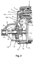
スターター駆動ユニット1の後部が断ち切られた図1の前部の図である図2において更によく分かるように、スターター駆動ユニット1は、ピニオン11を前部に備えるとともに、スターターの出力シャフト24が挿通する駆動ブシュと、レバー20のフォーク形状の下端を受ける溝とが設けられている駆動要素118を後部に備える。この図2において、参照番号20a,20bは、レバー20の上側関節軸および中間関節軸をそれぞれ示す。軸20bは、オーバーモールド成形によってプレート55と一体を成すプラスチック材料製の楕円形の支持穴36内に軸方向遊びをもって受けられる。参照番号116は、シャフト24の前端の外周とベアリング18の前側ベアリング上の中空円筒状の突出部の内周との間で径方向に位置するベアリング、ここではニードルローラベアリングを示す。ベアリング116は、ストッパ25により境界付けられる前部の平滑部22と後部の大径部110とを有するシャフト24が回転できるようにする。この大径部110にはその外周に、駆動要素118の駆動ブシュの後端の内周の一部を形成する螺旋溝29と共に作用するための螺旋溝28が設けられる。溝29は溝28を取り囲む。したがって、雌ネジおよび雄ネジが形成されたナット/スクリュータイプのシステムが形成され、溝29の歯が溝28の適合溝に入り込み、逆もまた同様である。したがって、スターター駆動ユニット1は、それがレバー20の下端によって移動されると、出力シャフト24に沿って回転動作および並進動作を成して駆動される。
As can be seen more clearly in FIG. 2, which is a front view of FIG. 1 with the rear portion of the
駆動要素118は、スプリングの力に晒されるアイドリングローラベアリング126によってピニオン11に軸方向で接続される。アイドリングベアリングは、ヒートエンジンが始動するときに駆動要素118の駆動ブシュがピニオン11およびリングギアCをモータMのシャフト26の回転方向に対応する回転方向に駆動させることができるようにする。ヒートエンジンの回転速度が閾値を超えると、アイドリングベアリングは、スターターの構成要素、特にスターターの電気モータを保護するために、ピニオン11の回転ドライブをシャフト26から離脱させる。
The
ピニオン11の歯は、アイドリングローラベアリング126の外側円筒状トラックを形成するべく過剰厚部によって後方に延ばされるスリーブ111に属する。このスリーブ111は、ブシュ124の介在によって平滑部22上で軸方向に案内され、ブシュ124は、平滑部22の外周と、ブシュ124と一体を成すスリーブの内周との間で径方向に位置する。スターター要素118のブシュは、シャフト24の軸Xに対して垂直に方向付けられるフランジによって前方へ延ばされる。このフランジはその外周において、前方に延びて軸方向に向けられる円筒状のスカートによって延ばされる。このスカートは、ローラ126およびそれらの関連するスプリングのためのハウジングを内側に形成するように構成される。これらのハウジングは、ローラ126の外側トラックを境界付けるとともに、ワッシャ130により取り囲まれる。ローラ126は、駆動ユニット118のフランジと、駆動要素のスカートの自由端に軸方向で当接するワッシャ130との間に軸方向で挿入される。このワッシャ130は、ここでは金属製であるキャップ131のベースによって所定位置に保持される。カップの形態を成すこのキャップ131は、駆動要素118のスカートを包み込むとともに、その自由端の材料が駆動要素118のフランジの外側面取り外周上に曲げ戻されることにより軸方向で固定される。
The teeth of the
レバー20のフォーク形状の下端を収容する溝は、駆動要素118のフランジと、駆動要素118のブシュの後端と一体を成すワッシャとによって境界付けられる。スターター駆動ユニット1のピニオン11は、引き込み休止位置において歯付きリングCから距離を隔てられる。移動コア部材2bが動作すると、レバー20の下端がピニオン11をストッパ25の方向でシャフト24に沿って軸方向に移動させる。
The groove that accommodates the fork-shaped lower end of the
2つの状況が生じ得る。第1の状況では、電気モータMが始動する前にピニオン11はリングギアCと噛み合い、ピニオン11の歯はリングギアCの歯を分離する溝形状の中空部に入り込む。その後、駆動要素の軸方向移動は、ピニオン11がストッパ25に当接するまで続く。
Two situations can arise. In the first situation, before the electric motor M starts, the
第2の状況では、ピニオン11の歯はリングギアCの歯と当接する。この場合、歯間押し付けスプリング5が圧縮され、特に電気モータが始動されるときに、ピニオンが回転してリングギアCと噛み合う。無論、変形例として、歯間押し付けスプリング5は、以下で言及される英国特許第225757号明細書に記載されるように制御レバーの内端に位置されてもよく英国特許第225757号明細書の図1〜図3は、歯付きスターターリングギアに対するピニオンの位置を示している。この英国特許第225757号明細書において、アイドリングベアリングは、カップおよびロッキングリングにより押圧される摩擦ディスクを備える。変形例において、摩擦クラッチは、請求項1の特徴部分の前の節に係る国際公開第2006/100353号パンフレットの場合のような円錐台タイプのものである。
In the second situation, the teeth of the
無論、ピニオンの歯がスターターリングギアの歯に当接する際にスターターリングギアがピニオンによって切削されるのを防止するため、以下で言及される国際公開第03/006824号パンフレットに記載されるような手段が設けられてもよく、それにより、電気モータは、最初に予回転と称される遅い速度で回転され、その後、全出力で回転され、駆動要素は、該駆動要素がその休止位置からそれがスターター駆動ギアと噛み合う位置へと通過するように、フォークと駆動要素との間の協働手段によって回転状態で固定される。回転中のこれらの固定手段は、インターロックタイプまたは摩擦タイプのものであってもよい。 Of course, to prevent the starter ring gear from being cut by the pinion when the pinion teeth abut the starter ring gear teeth, as described in WO 03/006824, referred to below. Means may be provided, whereby the electric motor is first rotated at a slow speed, referred to as pre-rotation, and then rotated at full power, and the drive element is decoupled from its rest position. Is fixed in rotation by cooperating means between the fork and the drive element so that it passes to a position that meshes with the starter drive gear. These fixing means during rotation may be of the interlock type or the friction type.
仏国特許第2631094号明細書において説明されるように、ヒートエンジンが始動すると、キックバック、すなわち、このエンジンの逆回転が出力シャフト24および駆動シャフト26へ伝えられるなど、ヒートエンジンが異常を来たす場合がある。ヒートエンジンが停止するときにも同じことが当てはまり、ヒートエンジンの1つ以上のピストンの最終下降中にヒートエンジンのクランクシャフト、ひいてはリングギアCが逆方向に回転する場合がある。
As described in French Patent No. 2631094, when the heat engine is started, the heat engine is abnormal, such as kickback, that is, the reverse rotation of the engine is transmitted to the
より具体的には、振動現象が終わるときにヒートエンジンの複数のピストンが同じ位置で停止することが分かってきた。 More specifically, it has been found that the pistons of the heat engine stop at the same position when the vibration phenomenon ends.
スターターリングギアCが完全に停止する前にスターターが始動される場合には、ピニオンがリングギアCとの歯間押し付け位置にあるときに、スターターの構造によりスターター、および、スターターから電気モータへのトランスミッションがこの回転に抗するという事実に起因して、リングギアCの回転はピニオン11を切削する場合がある。
When the starter is started before the starter ring gear C is completely stopped, when the pinion is in the interdental pressing position with the ring gear C, the starter structure and the starter to the electric motor Due to the fact that the transmission resists this rotation, the rotation of the ring gear C may cut the
これは、特に、電気モータのロータがヒートエンジンを始動させるための回転方向で既に駆動されるという事実に起因する。また、それは、ブラシと整流子との間の摩擦力、ロータの慣性、および、場合により減速ギアの存在によって生じる。 This is due in particular to the fact that the rotor of the electric motor is already driven in the direction of rotation for starting the heat engine. It is also caused by the friction between the brush and the commutator, the inertia of the rotor, and possibly the presence of a reduction gear.
スターター駆動ユニットのピニオンがリングギアCと係合して、クランクシャフトの抵抗トルクが電気モータの抵抗トルクよりも大きくなると、その電気モータの整流子が回転し、早期摩耗が生じさせ、或いは、ブラシの破壊までも発生させる。 When the pinion of the starter drive unit is engaged with the ring gear C and the resistance torque of the crankshaft becomes larger than the resistance torque of the electric motor, the commutator of the electric motor rotates and premature wear occurs, or the brush Even the destruction of.
振動が引き起こされる。より具体的には、ヒートエンジンが始動されると、スターターは、初期爆発を起こすことができるように、ヒートエンジンを休止状態から一般的には100rpmに近い最小速度に至るまで起動させなければならない。その後、スターターは、ヒートエンジンがその独立した走行速度に達するまで、ヒートエンジンに伴って駆動しなければならない。独立した走行速度は、一般に、4気筒エンジンの場合には300〜400rpmに向かうものであり、ヒートエンジンのアイドリング速度は、一般に、約750rpmである。 Vibration is caused. More specifically, when the heat engine is started, the starter must start the heat engine from rest to a minimum speed typically close to 100 rpm so that an initial explosion can occur. . The starter must then drive with the heat engine until the heat engine reaches its independent travel speed. The independent running speed is generally towards 300-400 rpm in the case of a four cylinder engine, and the idling speed of the heat engine is typically about 750 rpm.
したがって、ヒートエンジンが始動され或いは停止されると、スターター4は、ヒートエンジンの内部摩擦力に加えて、シリンダの抵抗圧縮力に打ち勝たなければならない。また、これらのシリンダにおける減圧段階の初めに、スターターの角加速度がヒートエンジンの角加速度を下回り、アイドリングベアリングが離脱を引き起こすように作用する。減圧段階の終わりに、ヒートエンジンは減速するが、スターターは、アイドリングベアリングが再び係合するまで、すなわち、スターターが再びエネルギーをヒートエンジンに伝えるまで、加速し続ける。 Therefore, when the heat engine is started or stopped, the starter 4 must overcome the resistance compression force of the cylinder in addition to the internal friction force of the heat engine. Also, at the beginning of the depressurization phase in these cylinders, the starter angular acceleration acts below the heat engine angular acceleration and the idling bearing acts to detach. At the end of the decompression phase, the heat engine decelerates, but the starter continues to accelerate until the idling bearing is re-engaged, i.e., the starter again transfers energy to the heat engine.
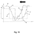
図15のグラフA(時間に対するヒートエンジンのrpm数)は前述した減少を示し、ヒートエンジンが停止するときに振動スペクトルが異なる。 Graph A (heat engine rpm number with respect to time) in FIG. 15 shows the aforementioned decrease, and the vibration spectrum is different when the heat engine stops.
特に、ピニオン11およびリングギアCは金属から成るという事実に起因して、結果的にノイズが生じ、また、ノイズは、特に、アイドリングベアリングが離脱される段階からアイドリングベアリングが係合される段階への移行時またはその逆の移行時に、スターターリングギアCとの噛み合い遊びの解消に起因する衝撃によってもたらされる。
In particular, due to the fact that the
この全ては、スターターがストップ&スタート機能を果たさなければならないときに顕著である。ストップ&スタート機能は、燃料消費量を減らすために、交通状態に起因して、例えば、赤信号または交通渋滞で停止するときに、ヒートエンジンを停止させて、その後に、ヒートエンジンを再始動させるために使用され得る。したがって、より頻繁な始動が起こる。 All this is noticeable when the starter has to perform a stop and start function. The stop & start function stops the heat engine and then restarts the heat engine when it stops due to traffic conditions, for example, red light or traffic jams, to reduce fuel consumption Can be used for. Thus, more frequent starting occurs.
これを行なうために、電子的に制御されるスターター回路が最も頻繁に使用され、また、欧州特許第146264号明細書において説明されるように、制御機能を果たし、特に、ヒートエンジンが回転しているときにスターターを始動させないマイクロコントローラが挿入される。 To do this, electronically controlled starter circuits are most often used and perform control functions as described in EP 146264, in particular when the heat engine rotates. A microcontroller is inserted that does not start the starter when
一般に、英国特許第225757号明細書に記載されるタイプの摩擦ディスクスターターを用いたとしても、先に述べたことから分かるように、依然として大きな衝撃およびノイズが引き起こされる。 In general, even with a friction disc starter of the type described in British Patent No. 225757, significant shock and noise are still caused, as can be seen from the foregoing.
この発明は、摩擦ディスクスターター駆動ユニットの枠の中で衝撃およびノイズを減らすという目的を有する。 The invention has the object of reducing impact and noise in the frame of the friction disc starter drive unit.
本発明によれば、引き込み休止位置と、ある種のヒートエンジンの歯付きスターターギアに噛み合うための前進位置との間で移動できる移動スターター駆動ユニット/制御レバーアセンブリは、
−前進位置で歯付きスターターリングギアと係合するためのピニオンが設けられ、軸方向対称軸を有するスターター駆動ユニットと、
−スターター駆動ユニットの一部を形成する駆動要素と、
−駆動ユニットとピニオンとの間の摩擦クラッチであって、このクラッチには、反作用プレートと、駆動要素と一体を成す圧力要素と、反作用プレートと圧力要素との間で締め付けられ得る少なくとも1つの摩擦要素とが設けられる、摩擦クラッチと、
を備え、
−圧力要素は、少なくとも一部がケーシング内に位置され、ケーシングは、ピニオンと一体して回転するとともに、摩擦クラッチの反作用プレートを構成するプレートを備えており、
−スターターの一部を形成する制御手段によって移動され得る上端と、スターター駆動ユニットに作用するための2つのアームを備えるフォーク形状の下端とを備える回動制御レバーを備えるタイプであり、
−制御レバーは、摩擦クラッチと係合するための手段と関連付けられ、
−制御レバーと摩擦クラッチと係合する手段との間に関節手段が存在し、
−レバーは、ケーシングがスターターリングギアと係合する前進位置へ向けて軸方向対称軸に沿って軸方向に最初に移動可能に構成され、一方、クラッチと係合するための手段は、次に摩擦クラッチと係合するために駆動ユニットを反作用プレートの方向で軸方向に移動させるように構成される、
ことを特徴とする。
In accordance with the present invention, a moving starter drive unit / control lever assembly that is movable between a retracted rest position and an advanced position for engaging a toothed starter gear of certain heat engines includes:
A starter drive unit provided with a pinion for engaging the toothed starter ring gear in the forward position and having an axially symmetrical axis;
A drive element forming part of the starter drive unit;
A friction clutch between the drive unit and the pinion, the clutch comprising a reaction plate, a pressure element integral with the drive element, and at least one friction that can be clamped between the reaction plate and the pressure element A friction clutch provided with an element;
With
The pressure element is at least partly located in the casing, the casing rotating integrally with the pinion and comprising a plate constituting a reaction plate of the friction clutch;
A type comprising a rotation control lever comprising an upper end that can be moved by control means forming part of the starter and a fork-shaped lower end comprising two arms for acting on the starter drive unit;
The control lever is associated with means for engaging the friction clutch;
A joint means exists between the control lever and the means for engaging the friction clutch;
The lever is configured to be initially movable axially along an axially symmetric axis towards an advanced position where the casing engages the starter ring gear, while the means for engaging the clutch is Configured to move the drive unit axially in the direction of the reaction plate to engage the friction clutch,
It is characterized by that.
本発明により、第1の段階において、レバーは、ケーシングをスターターリングギアの方向に移動させる。 According to the invention, in a first stage, the lever moves the casing in the direction of the starter ring gear.
係合手段は、制御レバーに対して遅延される第2の段階において作用する。これらの係合手段は、関節手段によって関節に装着されるレバーとは別個である。 The engaging means acts in a second stage which is delayed with respect to the control lever. These engaging means are separate from the lever mounted on the joint by the joint means.
したがって、第1の段階において、ピニオンは、スターターリングギアが依然として回転している間にスターターリングギアと噛み合うために両方向に自由に回転できる。 Thus, in the first stage, the pinion is free to rotate in both directions to engage the starter ring gear while the starter ring gear is still rotating.
第2の段階では、トルクを伝えるためにクラッチが係合される。 In the second stage, the clutch is engaged to transmit torque.
このように、クラッチの係合手段は遅延態様で作用する。 Thus, the clutch engagement means acts in a delayed manner.
ピニオンがスターターギアリングと噛み合うためにスターターリングギアに入り込むと、衝撃およびノイズが低減される。 Impact and noise are reduced when the pinion enters the starter ring gear to mesh with the starter gear ring.
ヒートエンジンを再始動できるようにするためにヒートエンジンが完全に停止するのを待つ必要性がない。ピニオンは、リングギアが逆方向に回転している場合であってもリングギアに入り込んでもよい。 There is no need to wait for the heat engine to stop completely so that the heat engine can be restarted. The pinion may enter the ring gear even when the ring gear is rotating in the opposite direction.
したがって、ピニオンの回転速度をスターターリングギアの回転速度に合わせて調整する機械的な同期装置が構成される。 Therefore, a mechanical synchronizer is configured that adjusts the rotation speed of the pinion in accordance with the rotation speed of the starter ring gear.
したがって、ヒートエンジンの2回の再始動間の時間を短くすることができる。 Therefore, the time between two restarts of the heat engine can be shortened.
本発明によれば、内燃ヒートエンジン、特に自動車のためのスターターは、そのような移動アセンブリを備えるという点において特徴付けられる。 According to the invention, internal combustion heat engines, in particular starters for motor vehicles, are characterized in that they comprise such a moving assembly.
単独で、および/または、組み合わせて解釈される他の特徴によれば、
−レバーの各アームは、ケーシングがスターターリングギアと噛み合う前進位置へ向けてケーシングを軸方向に移動させるためにケーシングと接触できるカムを形成するように外側に構成される突出シューを支持すし、
−ケーシングはカムの形状に外側が構成される突出シューを支持し、突出シューは、ケーシングがスターター歯付きリングと噛み合う前進位置へ向けてケーシングを軸方向に移動させるためにレバーの下端の関連するアームとそれぞれが接触でき、
−摩擦クラッチの係合手段は、レバーに接続されるとともに、クラッチと係合するために駆動ユニットに遅延をもって作用して駆動ユニットを反作用プレートの方向に押圧するように構成され、
−摩擦クラッチのための係合手段は、レバーの下端の関節に取り付けられるとともに、クラッチと係合するために駆動ユニットに遅延をもって作用して駆動ユニットを反作用プレートの方向に押圧するように構成される、摩擦クラッチ係合部材を組み込み、
−移動アセンブリはダブルレバーを備え、
−摩擦クラッチと係合するための手段は、制御レバーを該制御レバーの上端と下端との間で関節により装着可能に構成される更なる回動レバーを含み、
−更なるレバーは、遊びがなくなった後に制御レバー操作手段によって移動され得る上端を備え、
−更なるレバーは、制御レバーの上端と下端との間で制御レバーの関節に装着する支柱を有し、
−制御レバーは、重なりによって更なるレバーに装着され、 −摩擦クラッチと係合するための手段は、更なるレバーの下端の関節に接続されるとともにクラッチと係合するために駆動ユニットに遅延をもって作用して駆動ユニットを反作用プレートの方向に押圧するように構成される摩擦クラッチ係合部材を組み込み、
−ケーシングは、係合リングと、反作用プレートを係合リングに接続するスカートとを備え、カムの形態を成す各突出シューは、ケーシング係合リングと接触するように構成され、
−ケーシングは、ピニオンと反対の方向に向けられる反作用プレートの外周へと軸方向に延びる接続スカートを備え、カムの形態を成す各突出シューは、ケーシングの接続スカートと接触するように構成され、
−ケーシングは、ピニオンと反対の方向に駆動されるときに反作用プレートの外周へと軸方向に延びる接続スカートを備え、また、ケーシングには、カムの形状を成す突出シューが設けられ、カム形状の各突出シューは、制御レバーの適切なアームと接触するように構成され、
−ケーシングは、カムの形状を成す突出シューが設けられた係合リングと、反作用プレートを係合リングに接続するスカートとを備え、カム形状の各突出シューは、制御レバーの対応するアームと接触するように構成され、
−ケーシングは、ピニオンと反対の方向に向けられるときに反作用プレートの外周へと軸方向に延びる接続スカートを備え、カム形状の各突出シューは、ケーシングの接続スカートと接触するように構成され、
−カム形状の各突出シューは、全体的には平坦であるとともにケーシングの係合リングまたは接続スカートと接触できる或いは制御レバーの関連するアームと接触できる頂点部分を備え、
−各レバーアームの下端は丸みを帯びた部分を有し、シューの各頂点部分は、丸みを帯びた部分に接続される平坦部の方向に延びる傾斜離脱部分によってその内周が延ばされ、
−シューは、それらの頂点部分を介して、ケーシングの係合リングまたは接続スカートとそれらの2つの正反対の部分で接触する、すなわち、それらを支持するようになっており、
−クラッチ係合部材は、制御レバーのフォーク形状の下端に対してその下端のアーム間で関節により装着され、
−クラッチ係合部材は、更なるレバーのフォーク形状の下端に対してその下端のアーム間で関節により装着され、
−係合部材は、更なるレバーのフォーク形状の下端に対してその下端のアーム間で関節により装着される弓を構成し、
−弓はその各端部に軸を有し、各軸は、更なるレバーの下部を構成する関連するアームの穴に回転可能に装着され、
−弓は半円形状を成し、
−クラッチ係合部材は、駆動ユニットと一体を成す溝内に装着され、
−係合部材は、駆動ユニットと一体を成す溝内に装着される係合ヨークを備え、
−係合ヨークは、駆動ユニットと一体を成す溝内に装着されることが可能なように、その内周が開放し、
−係合ヨークは、バヨネットタイプの装着によって駆動部と一体を成す溝内に装着されることにより係合され、
−係合ヨークの開口は、溝に対する係合ヨークの径方向移動を可能にするように楕円形状を成し、
−係合ヨークは、少なくとも1つの外側部分によって互いに接続される2つの分岐部を備え、
−外側部分は円形状を成し、
−両分岐部の縁は平行であり、
−分岐部は、全体的に溝の底部の外径に対応する距離だけ互いから離間され、
−ヨークは、環状溝の側面のうちの一方を2つの正反対の部分で支持し、
−各分岐部は、レバーの関連するアームの下端に関節によって装着され、
−関連するアーム/分岐部要素のうちの一方は、関連するアーム/分岐部要素のうちの他方の一部を形成する穴に入り込む旋回軸を支持し、
−各分岐部は、各レバーアームの下端にある円筒状の穴に適合態様で入り込むことができる旋回軸を横方向で支持し、
−各レバーアームは、ヨークのアームの一方の一部をそれぞれ形成する穴内に適合態様で入り込む旋回軸を備え、
−旋回軸とその関連する穴との間に小さな径方向の遊びが存在し、
−環状溝の側面のうちの一方はより厚く、
−係合部分の分岐部は、軸方向の遊びをもって溝内に装着され、
−溝の底部は、駆動ユニットに適用される部材によって形成され、
−休止位置において、クラッチは、軸方向の遊びの出現によって離脱され、
−クラッチの係合部材を受ける溝の厚い方の側面は、軸方向の遊びよりも大きい厚さを有し、
−駆動部を休止位置へ向けて押し戻すために、軸方向の弾性的に作用するワッシャは反作用プレートと駆動部との間に配置され、
−弾性ワッシャは、反作用プレートの内周に位置する環状溝内に装着され、
−溝は駆動部の方向で開放し、
−溝は反作用プレートの内周において与えられる厚さの減少によって形成され、
−弾性ワッシャは波形ワッシャを構成し、
−摩擦クラッチは、圧力要素を備える駆動部の前部にあるハウジング内に固定される摩擦ライニングの形態を成す少なくとも1つの摩擦部材を備える、円錐台タイプの摩擦クラッチであり、
−このライニングはその外周に凸状円錐台摩擦面を有し、該凸状円錐台摩擦面は、少なくとも回転において、ピニオンと一体を成す反作用プレートの外周に位置する凹状円錐台摩擦面と共に適合態様で作用すし、
−摩擦クラッチは、駆動部と一体を成す圧力プレートの形態を成す圧力要素と反作用プレートとの間に位置する摩擦ディスクの形状を成す少なくとも1つの摩擦要素を備え、
−圧力プレートは、駆動部の一体のフランジを備え、
−ケーシング保持リングは、フランジの後面と共に作用できる肩部を形成するように、その内周に窪みが付けられ、
−摩擦クラッチは、軸方向の可動性を有して駆動部の前部と一体して回転する2つの摩擦ディスクを組み込み、
−クラッチは、反作用プレートと一体して回転する3つの摩擦ディスクを備え、
−3つの摩擦ディスクは、ケーシングのスカートを介して、軸方向の可動性をもって反作用プレートと一体して回転し、
−駆動部の前部と一体して回転する各ディスクは、摩擦ディスクが交互配置になるように、スカートと一体して回転する2つの摩擦ディスク間に配置され、
−ケーシング保持リングの内径は、クラッチの係合部材を受ける溝の厚い方の側面の外径よりも大きく、
−ケーシングのスカートの内径は、クラッチの係合部材を受ける溝の厚い方の側面の外径よりも大きく、
−厚い方の側面はケーシングに部分的に入り込み、
−駆動要素のピニオンは、反作用プレートのスリーブと一体を成し、
−ピニオンは、反作用プレートと一体のスリーブと軸方向の可動性をもって一体して回転し、
−反作用プレートと、反作用プレートと一体を成すスリーブに軸方向の可動性をもって装着されるピニオンとの間に、弾性部材が配置されている。
According to other features that are interpreted alone and / or in combination,
Each arm of the lever supports a protruding shoe configured on the outside to form a cam that can contact the casing to move the casing axially toward an advanced position where the casing meshes with the starter ring gear;
The casing supports a protruding shoe whose outer shape is configured in the form of a cam, the protruding shoe being associated with the lower end of the lever to move the casing axially towards an advanced position in which the casing engages the starter toothed ring Each arm can contact,
The engagement means of the friction clutch is connected to the lever and is configured to act on the drive unit with a delay to engage the clutch and press the drive unit in the direction of the reaction plate;
-The engagement means for the friction clutch is attached to the joint at the lower end of the lever and is configured to act on the drive unit with a delay to engage the clutch and press the drive unit in the direction of the reaction plate. Incorporating a friction clutch engaging member,
The moving assembly comprises a double lever;
The means for engaging the friction clutch comprises a further rotating lever configured to allow the control lever to be mounted by a joint between the upper and lower ends of the control lever;
The further lever comprises an upper end which can be moved by means of a control lever operating means after play has been eliminated;
The further lever has a post that attaches to the joint of the control lever between the upper and lower ends of the control lever;
The control lever is attached to the further lever by overlapping; the means for engaging the friction clutch is connected to the joint at the lower end of the further lever and with a delay in the drive unit to engage the clutch Incorporating a friction clutch engaging member configured to act and push the drive unit in the direction of the reaction plate;
The casing comprises an engagement ring and a skirt connecting the reaction plate to the engagement ring, each projecting shoe in the form of a cam configured to contact the casing engagement ring;
The casing comprises a connecting skirt extending axially to the outer periphery of the reaction plate directed in the direction opposite to the pinion, each protruding shoe in the form of a cam being configured to contact the connecting skirt of the casing;
The casing is provided with a connecting skirt extending axially to the outer periphery of the reaction plate when driven in the direction opposite to the pinion, and the casing is provided with a protruding shoe in the shape of a cam, Each protruding shoe is configured to contact the appropriate arm of the control lever,
The casing comprises an engaging ring provided with a cam-shaped protruding shoe and a skirt connecting the reaction plate to the engaging ring, each cam-shaped protruding shoe contacting the corresponding arm of the control lever Configured to
The casing comprises a connection skirt extending axially to the outer periphery of the reaction plate when oriented in the direction opposite to the pinion, each cam-shaped protruding shoe being configured to contact the connection skirt of the casing;
Each cam-shaped projecting shoe is generally flat and has an apex portion that can contact the engaging ring or connecting skirt of the casing or contact the associated arm of the control lever;
The lower end of each lever arm has a rounded portion, and each apex portion of the shoe has its inner circumference extended by an inclined detachment portion extending in the direction of a flat portion connected to the rounded portion;
-The shoes, through their apex parts, come into contact with, i.e. support, their two opposite parts with the engagement ring or connecting skirt of the casing;
The clutch engaging member is mounted by a joint between the lower arm of the fork-shaped lower end of the control lever;
The clutch engaging member is mounted by a joint between the lower arm of the fork-shaped lower end of the further lever;
The engaging member constitutes a bow which is mounted by a joint between the lower arm of the fork-shaped lower end of the further lever;
The bow has an axis at each end thereof, each axis being rotatably mounted in a hole in the associated arm that forms the lower part of the further lever;
-The bow is semicircular,
The clutch engaging member is mounted in a groove integral with the drive unit;
The engagement member comprises an engagement yoke mounted in a groove integral with the drive unit;
The engagement yoke is open on its inner circumference so that it can be mounted in a groove integral with the drive unit;
-The engaging yoke is engaged by being mounted in a groove that is integral with the drive unit by mounting the bayonet type,
The opening of the engagement yoke is elliptical so as to allow radial movement of the engagement yoke relative to the groove;
The engagement yoke comprises two branches connected to each other by at least one outer part;
The outer part is circular,
-The edges of both branches are parallel;
The branches are separated from each other by a distance generally corresponding to the outer diameter of the bottom of the groove;
The yoke supports one of the sides of the annular groove with two diametrically opposite parts;
Each branch is attached by a joint to the lower end of the associated arm of the lever;
One of the associated arm / branch elements supports a pivot axis that enters a hole that forms part of the other of the associated arm / branch elements;
-Each bifurcation supports laterally a pivot that can fit into a cylindrical hole in the lower end of each lever arm in a conforming manner;
Each lever arm comprises a pivot shaft that fits into a hole that forms part of one of the arms of the yoke,
-There is a small radial play between the pivot axis and its associated hole,
-One of the sides of the annular groove is thicker,
The bifurcation of the engaging part is mounted in the groove with axial play;
The bottom of the groove is formed by a member applied to the drive unit;
In the rest position, the clutch is disengaged by the appearance of axial play;
The thicker side of the groove receiving the engagement member of the clutch has a thickness greater than the axial play;
An axially elastic washer is arranged between the reaction plate and the drive to push the drive back towards the rest position;
The elastic washer is mounted in an annular groove located on the inner periphery of the reaction plate;
The groove opens in the direction of the drive,
The groove is formed by a reduction in thickness provided at the inner circumference of the reaction plate;
The elastic washer constitutes a corrugated washer,
The friction clutch is a frustoconical type friction clutch comprising at least one friction member in the form of a friction lining fixed in a housing in front of the drive with pressure elements;
The lining has a convex frustoconical friction surface on its outer circumference, which conforms with a concave frustoconical friction surface located on the outer periphery of the reaction plate integral with the pinion at least in rotation. It works with
The friction clutch comprises at least one friction element in the form of a friction disk located between a pressure element in the form of a pressure plate integral with the drive and the reaction plate;
The pressure plate comprises an integral flange of the drive,
The casing retaining ring is recessed on its inner periphery so as to form a shoulder that can act with the rear face of the flange;
The friction clutch incorporates two friction discs having axial mobility and rotating integrally with the front of the drive,
The clutch comprises three friction discs that rotate integrally with the reaction plate;
-The three friction discs rotate together with the reaction plate with axial mobility through the casing skirt,
Each disk rotating integrally with the front part of the drive is arranged between two friction disks rotating integrally with the skirt so that the friction disks are interleaved;
The inner diameter of the casing retaining ring is greater than the outer diameter of the thicker side of the groove receiving the clutch engagement member;
The inner diameter of the casing skirt is greater than the outer diameter of the thicker side of the groove receiving the clutch engagement member;
-The thicker side part partially enters the casing,
The pinion of the drive element is integral with the sleeve of the reaction plate;
-The pinion rotates integrally with the sleeve that is integral with the reaction plate and axially movable,
An elastic member is arranged between the reaction plate and a pinion that is mounted axially on a sleeve integral with the reaction plate;
本発明の他の特徴および利点は、以下の非限定的な説明を読むことにより明らかとなり、その理解のために添付図面が参照される。 Other features and advantages of the present invention will become apparent upon reading the following non-limiting description and reference will be made to the accompanying drawings for an understanding thereof.
図には、同一の、同様の、または、類似する要素が同じ参照番号によって示される。 In the figures, identical, similar or similar elements are indicated by the same reference numerals.
前後方向は図1,3,4の左右方向に相当する。 The front-rear direction corresponds to the left-right direction in FIGS.
本発明に係るスターター駆動ユニット1は、図1および図2のスターター駆動ユニット1の位置に該スターター駆動ユニット1の代わりに装着される。スターター駆動ユニットは、スターターの出力シャフト24の対称軸Xと同じ対称軸を備える。
The
図中、軸方向、径方向、および、垂直方向は、シャフト24およびスターター駆動ユニット1のこの軸Xに対して規定される。
In the drawing, the axial direction, the radial direction, and the vertical direction are defined with respect to this axis X of the
このスターター駆動ユニット1は、熱機関のスターター歯付きリングギアCと噛み合うことができるピニオン11と、駆動要素118と、駆動要素118とピニオン11との間に位置する摩擦クラッチ300とを備える。このクラッチ300は、ピニオン11と駆動要素118との間にアイドリング機械リンクを備えるように構成される。これを達成するため、クラッチは、圧力要素と、反作用プレート112と、プレート112と圧力要素との間に位置する少なくとも1つの摩擦要素301とを備える。クラッチは、シャフト24からのトルクを、ピニオン11を介してギアリングCへ伝えるために、圧力要素により及ぼされる締め付け力を受けて直接的または間接的のいずれかにより反作用プレート112と摩擦接触することができる。
The
ピニオン11およびギアリングCの歯は、X軸に対して軸方向に向けられる。
The teeth of the
したがって、ピニオン11がギアリングCとの噛合位置にある前進位置(図10および図11)では、クラッチ300が係合される。このとき、トルクはシャフト24からギアリングCへと伝えられる。このとき、ピニオン11は駆動要素118と回転状態で連結される。
Therefore, in the forward position (FIGS. 10 and 11) where the
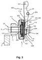
スターター駆動ユニット1の引き込み休止位置(図3および図4参照)では、クラッチ300は、1つの特徴にしたがって、ピニオン11が自由に回転できるように離脱される。
In the retracted rest position of the starter drive unit 1 (see FIGS. 3 and 4), the clutch 300 is disengaged according to one feature so that the
クラッチ300は、以下で言及される国際公開第2006/100353号パンフレットに記載される円錐台タイプの摩擦クラッチであってもよい。したがって、クラッチは、圧力要素を備える駆動要素118の前部にあるハウジング内に固定される摩擦ライニングの形態を成す少なくとも1つの摩擦要素を備える(前記国際公開第2006/100353号パンフレットの図2〜図5参照)。このライニングはその外周に凸状円錐台摩擦面を有し、該凸状円錐台摩擦面は、少なくとも回転において、ピニオンと一体を成す反作用プレートの外周に設けられる凹状円錐台摩擦面と共に適合態様で作用する。
The clutch 300 may be a truncated cone type friction clutch described in International Publication No. 2006/10033 pamphlet mentioned below. The clutch thus comprises at least one friction element in the form of a friction lining that is fixed in a housing in front of the
この反作用プレートは、その外周に、リングを後端に備えるキャップの取り付けのための延長部を有し、スターター駆動ユニットがリングの中心を通過する。このキャップは、反作用プレートの延長部に取り付けられる環状スカートを有する。したがって、摩擦ライニングは、反作用プレートと、リングと、反作用プレートをリングに接続するスカートとを備えるケーシング内に収容され、リングはケーシングの係合リングを構成し、ケーシング内に部分的に組み込まれる圧力要素を備える駆動要素118は前記係合リングを通過する。
The reaction plate has, on its outer periphery, an extension for attaching a cap having a ring at the rear end, and the starter drive unit passes through the center of the ring. The cap has an annular skirt that is attached to an extension of the reaction plate. Thus, the friction lining is housed in a casing comprising a reaction plate, a ring, and a skirt connecting the reaction plate to the ring, the ring constituting the engagement ring of the casing and the pressure partially incorporated in the casing
変形例として、図3〜図13に示されるように、摩擦クラッチ300は、駆動要素118と一体の圧力プレート120の形態を成す圧力要素と反作用プレート112との間に位置する摩擦ディスク301の形態を成す少なくとも1つの摩擦要素を備えてもよい。
As an alternative, as shown in FIGS. 3 to 13, the
後述する態様で、ディスク301は、係合リング114を備えるケーシング112,113,114内にも収容され、駆動要素118は係合リング114の中心を通過する。ディスクは垂直方向の向きを有する。図3〜図13において、これらの前後面は互いに平行である。
In a manner to be described later, the
圧力プレートはケーシング内に組み込まれる。 The pressure plate is incorporated in the casing.
本発明は、一般的には、圧力要素の少なくとも一部が内部に位置するケーシングの存在に部分的に基づく。好適には、圧力要素118,120は、軸方向の遊びの制限内で、反作用プレート112に対して軸方向に移動できる。好ましくは、この軸方向の遊びは弾性スプリング400によって確保され、該弾性スプリングは、駆動要素118に作用して該駆動要素を後方へ押圧するために、反作用プレート112に軸方向支持して作用する。
The present invention is generally based in part on the presence of a casing in which at least a portion of the pressure element is located. Preferably, the
本発明は、部分的に、ケーシングの係合リング114に基づく。
The present invention is based in part on the
変形例として、本発明は、部分的に、ケーシングのスカート113に基づいてもよい。
As a variant, the invention may be based in part on the
摩擦ディスク301は、ディスク301が駆動要素118に対して軸方向に移動できるようにする適合形状接続によって駆動要素118に回転状態で接続されてもよい。
The
他の実施形態において、ディスク301は、圧力プレート120と一体を成してもよく、また、反作用プレート112と直接的または間接的のいずれかによって接触してもよい。
In other embodiments, the
更なる他の実施形態において、ディスク301は、反作用プレートと一体を成してもよく、また、圧力プレート120と直接的または間接的のいずれかによって接触してもよい。
In still other embodiments, the
スターター駆動ユニット1が引き込み休止位置(図3および図4参照)にあるときに、摩擦ディスク301と圧力プレート120との間に軸方向の遊びがあることが好ましい。円錐台タイプの前述した摩擦クラッチの場合には、反作用プレートと摩擦ライニングとの間に軸方向の遊びがあることが好ましい。この遊びは、ピニオン11が駆動要素118に対して回転できるようにし、また、圧力要素118,120が反作用プレート112に対して軸方向に移動できるようにする。
Preferably, there is axial play between the
この遊びは、好適には、反作用プレート112と駆動要素118との間に位置されて軸方向で作用する弾性ワッシャ400によって確保されてもよい。このワッシャ400は、反作用プレート112の後面に当接するとともに駆動要素118の前面に作用して、駆動要素を後方へ、ひいては、引き込み休止位置へ向けて押圧する。この構成は、駆動要素に対するピニオン11のより良い回転に有利に働くとともに、圧力プレート120からのディスク301のより良い取り外し或いは反作用プレート112からの摩擦ライニングのより良い取り外しに有利に働く。
This play may preferably be ensured by an
このワッシャ400は、シャフト24の螺旋溝28と係合適合する螺旋溝29を備える駆動要素118の取り外しの速度を高める。したがって、このワッシャ400は、駆動要素118のねじ外しに有利に働き、そのため、取り外し時間を減少させる。
This
また、この構成はノイズも減少させる。これは、この構成により、クラッチ300が係合されないときに駆動要素118と反作用プレート112との間の接触が防止されるからである。
This configuration also reduces noise. This is because this arrangement prevents contact between the
ピニオン11がリングギアCと係合する前進位置(図10および図11)では、ディスク301がプレート112,120に対して耐密に保持される。このとき、トルクがシャフト24からリングギアCへ伝えられる。このとき、ピニオン11は駆動要素118と回転状態で連結される。
In the forward movement position where the
圧力プレート120は駆動要素118と一体を成し、一方、反作用プレート112(図4および図10)は、ピニオン11と一体して回転するとともに、ケーシング112,113,114に属する。プレート120,112は垂直方向に向けられて互いに平行である。
The
図1および図2に示されるように、また、例えば図3および図4に見られるように、ピニオン11は、軸方向に向けられるスリーブ111に支持されてもよい。このスリーブ111は、反作用プレート112によってその後端が延ばされる。このプレート112はそれ自体がその外周において、軸方向に向けられる環状スカート113によって延ばされる。このスカート113は、駆動要素118の方向で後方へと方向付けられる。
As shown in FIGS. 1 and 2 and as seen, for example, in FIGS. 3 and 4, the
したがって、スカート113は、ピニオン111と反対の方向に向けられることによって反作用プレート112の外周へと軸方向に延びる。
Therefore, the
スリーブ111の存在は不可欠ではなく、ピニオン11は、前述した国際公開第2006/100353号パンフレットの図の場合と同様に反作用プレートと一体を成してもよい。
The presence of the
スリーブ111の長さは用途によって決まる。
The length of the
反作用プレート112はスリーブ111と一体を成してもよい。変形例として、反作用プレート112は、スリーブ111とは別個であり、例えばボルト締め、リベット、ねじなどの固定部材の使用、または、溶接によってスリーブ111に組み付けられる。変形例として、スリーブ111は、垂直方向に向けられる壁によって後方に延ばされる。この壁は、例えば壁にオーバーモールドされる鋳鉄の反作用プレート112との組み付けのために穿孔されてもよい。これらの変形例において、プレート112の材料は、それが適切な摩擦係数を有するように選択されてもよい。
The
スカート113は、反作用プレート112と一体を成してもよい。
The
変形例として、スカート113は、反作用プレート112とは別個であってもよく、例えばボルト締め、リベット、ねじなどの固定部材の使用、または、溶接によって反作用プレートに組み付けられてもよい。変形例として、前述したようにスリーブ111を延ばす壁は、それ自体が軸方向スリーブによって延ばされ、該軸方向スリーブは、スカートをオーバーモールドによってこの軸方向スリーブと組み付けることができるように穿孔される。これらの2つのケースにおいて、スカート113の材料は、スカートが果たさなければならない機能のために必要な品質をスカートが有するように選択されてもよい。
Alternatively, the
変形例として、後述する態様において、スカート113は、キャップ230によって反作用プレートに組み付けられる。このスカートは、国際公開第2006/100353号パンフレットの場合と同様にキャップに属してもよい。
As a modification, the
ピニオン11は、図3〜4および図8〜11の場合と同様に、スリーブ111と一体を成してもよい。
The
変形例として、ピニオン11は、図12および図13に見られるように、スリーブ111と別個であってもよく、軸方向移動の可能性を伴ってスリーブ111と回転状態で一体であってもよい。
As a variation, the
変形例として、ピニオン11は、圧着または溶接によってスリーブ111に取り付け固定される。
As a modification, the
以上から分かるように、機械的に強固なスチールなどのピニオン11の材料、および、反作用プレート112およびスカート113の材料は、それらが果たさなければならない機能にしたがって最適な方法で選択されてもよい。
As can be seen, the material of the
ピニオン11の材料のグレードは、ギアリングCと噛み合う必要性(機械的強度、耐摩耗性、低雑音放射など)に適してもよく、一方、反作用プレート112の材料のグレードは、トルクの係合および伝達の必要性(耐摩耗性、摩擦係数の値、機械的強度など)に特に適してもよい。
The material grade of the
ピニオン11および反作用プレート112は、例えば金属の機械加工または熱処理によって得られてもよい。
The
変形例として、ピニオン11および反作用プレート112は、成形によって、特に焼結によって得られる。焼結は、反作用プレート112がピニオン11と一体を成すときに2つの材料を焼結することを含んでもよい。これは、反作用プレート112と共に成形することによって得られてもよいスカート113にも適用される。
As a variant, the
変形例として、プレート112には、その摩擦係数が摩擦ディスク301の摩擦係数に適合する層が設けられてもよい。この構成の結果として、プレート112の材料は、金属ピニオン11の材料と同じであってもよい。この層は、例えば、反作用プレート112の後面に接着結合される。
As a modification, the
変形例として、後述する態様では、層が摩擦ディスク302と置き換えられ、この摩擦ディスク302は、該ディスク302が反作用プレート112に対して軸方向に移動できるようにする適合形状接続によって、反作用プレート112と一体を成すスカート113と回転状態で接続される。変形例として、摩擦ディスク302は、接着結合または別の方法により反作用プレートに取り付けられてもよい。
Alternatively, in the embodiment described below, the layer is replaced with a
前記特徴の全てがクラッチの圧力プレート120に適用され、該圧力プレート120は、駆動要素118により支持される駆動ブシュ119に取り付け固定されてもよく、或いは、変形例では、ブシュ119と一体を成す垂直方向壁にオーバーオールドされてもよく、或いは、そのブシュ119と一体を成してもよい。全てのケースにおいて、圧力プレート120は駆動要素118に属する。このプレート120は、駆動要素118と一体を成し、ブシュ119を介して取り付け固定される。
All of the above features apply to the
したがって、1つの実施形態では、プレート112,120は鋳鉄から成ってもよい。そのため、変形例において、プレート120には、摩擦ディスク301の摩擦係数に適合する摩擦係数を有する層が設けられてもよい。
Thus, in one embodiment, the
スターター駆動ユニット1は、図1および図2の場合と同様、制御レバー20を備える移動アセンブリ500に属する。このアセンブリ500は、ピニオン11がスターター歯付きリングCから距離を隔てている引き込み休止位置(図3)とピニオンがスターターリングギアCと噛み合う前進位置(図11)との間で移動でき、前進位置では、ピニオンは図2のストッパ25に当接する。
The
本発明によれば、このアセンブリ500は、リングギアが回転を停止する前にピニオン11がリングギアCと噛み合うことができるようにする同期装置を形成するように、後述する態様で構成される。したがって、ノイズを最小限に抑えてピニオン11の歯とリングギアCの歯との間の衝撃を減らしつつ、リングギアCの回転が完全に停止する前にヒートエンジンをより素早く再始動させることができる。したがって、ヒートエンジンの2回の連続する再始動間の時間を減少させることができる。
In accordance with the present invention, this
レバー20は、図1および図2の電磁コンタクタ2によってレバー20の上端を移動できるような方法で、図1および図2のレバーの代わりに図1および図2のレバーの位置に取り付けられる。
The
1つの特徴によれば、この移動アセンブリ500は、摩擦クラッチ300のための係合手段200−200A,120Aを備える。これらの係合手段200−200A,120Aは、制御レバー20と関連付けられるとともに、駆動要素118に遅延をもって作用し且つ駆動要素を摩擦クラッチ300と係合させるべく反作用プレート112の方向に押圧するように構成される。これは、移動アセンブリが休止位置からスターターリングギアと噛み合う前進位置へ移動するときに、言い換えると、リングギアCと係合してリングギアCを駆動させる段階中に引き起こされる。
According to one feature, the moving
これらの係合手段200−200A,120Aはレバー20に接続される。1つの特徴によれば、レバー20とこれらの係合手段200−200A,120Aとの間に関節手段が存在する。
These engaging means 200-200A, 120A are connected to the
1つの特徴によれば、レバー20は、最初にケーシング112,113,114をスターターリングギアCと噛み合う前進位置へ向けて軸方向対称軸Xに沿って軸方向に移動できるように構成され、一方、摩擦クラッチと係合するための手段は、第2の段階で駆動要素118を反作用プレート112の方向に軸方向移動させて摩擦クラッチ300と係合させるように構成される。
According to one feature, the
1つの特徴によれば、摩擦クラッチ300のための係合手段は、摩擦クラッチ300のための係合部材200,200Aを備えてもよい。
According to one feature, the engagement means for the
この部材200は、特に図6および図7において明らかなように、レバー20の下端240,241,242に取り付けられてもよい。
This
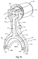
この要素200Aは、特に図16および図17に見られるように、更なるレバー120Aの下端に取り付けられてもよい。
This
制御レバー20および更なるレバー120Aのそれぞれに対する係合部材200,200Aの取り付けは関節取り付けであり、関節手段は、係合部材とその関連するレバーとの間に位置する。
The attachment of the
係合部材は、駆動要素118に遅延をもって作用するとともに駆動要素をクラッチ300と係合させるべく反作用プレート112の方向に押圧するように構成される。レバー20は、前述のケーシング112,113,114に作用して、該ケーシングをリンギギアCと噛み合う前進位置へ向けて軸方向に移動させるように、前述の態様で構成される。ケーシングは軸Xおよびシャフト24に沿って軸方向に移動される。レバー20は、前述したように、部材200,200Aを駆動要素118に係合させることにより遅延をもって及ぼされる締め付け作用の前に、最初にケーシングに作用するようになっている。
The engaging member is configured to act on the
図3〜図13において、この係合部材は、クラッチ300のための係合ヨーク200を備える。
3 to 13, the engagement member includes an
1つの特徴によれば、ヨーク200は、レバー20のフォーク形状の下端240,241,242に関節により装着される(図6および図7)。ヨークは、そのレバー20の下端のフォーク内に装着される。
According to one feature, the
このヨーク200は、駆動要素118と一体を成す溝223(図4,5,10)に嵌まり込むために、その内周が開放してもよい(図7)。そのような組み付けは容易であり、取り付けられた状態でレバー20に装着されるヨーク200は、従来のスターターのレバー20と同じ方法で溝223内に径方向から挿入される。
The
変形例として、ヨーク200は、閉じられており、バヨネットタイプの装着によって溝223内に装着されてもよい。全てのケースにおいて、ヨーク200の開口は、形状が楕円であり、ヨーク200が溝223に対して径方向に移動できるように、X軸に対して垂直である。
As a modification, the
溝233は、垂直に方向付けられる2つの側面によって境界付けられる。溝の断面は全体的にU形状を成す。 The groove 233 is bounded by two side surfaces that are oriented vertically. The cross section of the groove is generally U-shaped.
溝223の側面のうちの一方は、例えば図4、図5、および図10に見られるように他方の側面より厚くてもよい。これらの図においては、溝223の前側の側面224の方が厚い。
One of the side surfaces of the
溝223は、駆動要素118に取り付けられる、より具体的には、ピニオン119の外周面上に取り付けられる、全体がU形状断面の環状部材123によって形成されてもよい。部材123および係合ヨーク200は、ノイズを減らすためにプラスチック材料から成ってもよい。
The
ヨーク200は、溝223の前側の側面224に作用するように構成される。ヨークは、2つの正反対の領域で、厚い方の側面であるこの前側の側面224を支持できる。
The
図4および図10を参照すると、側面224がリング114の内部に部分的に入り込むに気付く。側面の外径はリングの内径よりも小さい。これにより、スターター駆動ユニット1の軸方向寸法を減らすことができる。
With reference to FIGS. 4 and 10, it is noted that the
したがって、本発明に係るスターター駆動ユニット1は、螺旋溝28を備える出力シャフト24の部分110の通過のために中心が中空である駆動要素118を備える(図3〜図5参照)。この駆動要素118は、その後方に、シャフト24の螺旋溝28と適合する形状の螺旋溝29が内周面の内側に設けられる駆動ブシュ119を備える。
Accordingly, the
前述したワッシャ400は、溝29が溝28からねじって外れる速度を高める。
The
図2の場合と同様、ブシュ119は、図3に部分的に示されるスターターの出力シャフト24のX軸に対して垂直に方向付けられるフランジ120によって前側が境界付けられる。
As in FIG. 2, the
このシャフト24は、図1のストッパ25の装着ロッドを受けるための中空部(参照符号を付さない)を伴う平滑部分22を前側に有する。本発明のこの実施形態において、ベアリング124は、中心が中空のスターター駆動ユニットの金属ピニオン11と一体を成す。このベアリング124は、平滑部分22の外周面と、平滑部分22が通過する円筒状の中心孔を画定するピニオン11の内周面とに抗して作用する。
The
例示される図において、クラッチ300のための係合ヨーク200を受けるように形成される環状部材123は、ブシュ119の外周に圧力嵌めされる。U形状断面のこの部材123は、その内周面によりブシュ119の外周面と接触してX軸に対して軸方向に方向付けられる環状ベース(図4および図10において参照符号を付さない)と、そのX軸に対して垂直に方向付けられる2つの側面とを備える。前側の側面は、その前面によってフランジ120の後面と接触する。この前側の側面は、溝223の厚い方の側面224を構成する。部材123は、フランジ120の後面とブシュ119の前端との接合丸み部と干渉しないように、前側が面取りされる。図4および図10においては、溝122を機械加工できるように、部分121の後端とフランジ120の前面との間にスロット(参照符号を付さない)が存在する。
In the illustrated view, an
フランジ120は、ここでは、環状の形状を成す。フランジの直径は、図1および図2の駆動要素118の直径よりも小さい。フランジ120の外径は、1つの特徴によれば、部材123のその側面の外径を成す外径よりも大きい。部材123はフランジ120に軸方向で当接する。
Here, the
1つの特徴によれば、この実施形態において、フランジ120は、少なくとも1つの摩擦ディスク301を備える摩擦クラッチ300の前述した圧力プレートを構成する。駆動要素118と一体を成すこのフランジ120は、ケーシング112,113,114内に組み込まれる。
According to one feature, in this embodiment, the
この摩擦クラッチ300は、図1および図2のアイドリングローラベアリングに取って代わる。摩擦クラッチ300は、駆動要素118とピニオン11との間の取り付けの離脱可能手段を備える。この離脱可能手段は、スターター駆動ユニットが前進休止位置にあるときにピニオン11が両方向に回転できるようにする。
This friction clutch 300 replaces the idling roller bearing of FIGS. The
これを行なうために、スターター駆動ユニットは、ここでは、前方に、軸方向に向けられた溝122を備える部分121を有する。この部分121は、反作用プレート112とスカート113とによって境界付けられるキャビティ内に入り込む。したがって、前記部分は、このキャビティ内に組み込まれる。
To do this, the starter drive unit here has a
図3〜図13の実施形態において、ディスク301は、その内周に、溝122に適合して入り込む突起を有する。
In the embodiment of FIGS. 3 to 13, the
ディスク301は、軸方向移動の可能性をもって形状相互作用により駆動要素118と回転状態で接続される。反作用プレート112はフランジ120と平行に延びる。
The
反作用プレート112の外径は、フランジ120の外径よりも大きい。
The outer diameter of the
ピニオン11は、スリーブ111の外径よりも大きい外径を有する。
The
図3〜図11の実施形態において、ピニオン11はスリーブ111と一体を成し、スリーブ111は、それ自体が反作用プレート112と一体を成し、反作用プレート112はその外周において、円筒状のスカート113によって延ばされる。スカート113は、フランジ120の方向で軸方向後方に方向付けられる。スカート113の内周は、駆動要素118の部分121と平行に、該部分121から径方向に距離を隔てて延びる。
In the embodiment of FIGS. 3 to 11, the
したがって、スカート113と部分121との間には、ディスク301を収容するキャビティが形成される。
Therefore, a cavity for accommodating the
ディスク301の外径はスカート113の内径よりも小さく、一方、ディスク301の内径は部分121の外径と全体的に同じである。ディスク301の内側突起のサイズは、溝122の深さによって決まる。
The outer diameter of the
この実施形態では、前述したように、摩擦ディスク302は、反作用プレート112と一体に、このプレート112の後面に隣接して回転する。
In this embodiment, as described above, the
これを行なうために、スカート113は、内側に過剰厚部(参照符号を付さない)を有する。この過剰厚部の内周に軸方向溝322が形成される。ディスク302は、軸方向可動性をもって形状干渉により反作用プレート112に回転接続するため、溝322に適合して入り込む突起(参照符号を付さない)をその外周に有する。
In order to do this, the
ディスク302の外径は、全体的にはスカート113の過剰厚部の内径と同じであり、一方、ディスク302の内径は、全体的には部分121の外径と同じである。ディスク302の外側突起のサイズは、溝322の深さによって決まる。
The outer diameter of the
ディスク301,302の突起の数は、トルクの最大伝達のため、適合する溝122,322のそれぞれの数と同じであってもよい。変形例として、突起の数は、伝えられるべきトルクが小さい場合には、適合する溝122,322の数より少なくてもよい。
The number of protrusions on the
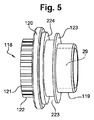
ディスク301,302の突起および適合する溝122,322は、全体的には台形形状であってもよい(図5)。
The protrusions of the
他の実施形態において、ディスク301,302の突起および適合する溝122,322は、全体的には半円の断面を有する三日月形状であってもよい。
In other embodiments, the protrusions of the
更なる他の実施形態において、ディスク301,302の突起および適合する溝122,322は、全体的には長方形状であってもよい。
In still other embodiments, the protrusions of the
ディスク301,302の数は、より大きなトルクを伝えるために、スターター駆動ユニット1の直径を増大させることなく、増大されてもよい。図では、2つの摩擦ディスク301が設けられる。変形例として、更に多くの数のディスク301,302が設けられてもよい。
The number of
ディスク301,302は、例えば少なくとも1つの熱硬化性樹脂と、グラファイト、シリカ、金属粉、および、繊維(例えばKevlar(著作権)などのアラミド繊維)とを備えるバインダーから得られる有機タイプのものであってもよい。
The
変形例として、ディスク301,302は、高温加圧下で凝集された銅および鉄などの金属粉末を備える焼結タイプのものであってもよい。
As a modification, the
他の変形例として、ディスク301,302は、金属タイプのものであってもよく、また、例えば銅または鉄の合金を備えてもよい。
As another variant, the
更なる他の変形例として、ディスク301,302は、金属であってもよく、また、前述したタイプ、すなわち、有機または焼結の例えば摩擦ライニングでそれぞれの表面が裏打ちされてもよい。
As yet another variation, the
この場合、ディスクの突起301,302は金属製である。
In this case, the
図に示される実施形態では、3つの摩擦ディスク302が設けられるが、代わりの態様では、2つの摩擦ディスク301が設けられ、ディスク302の摩擦係数はフランジ120の摩擦係数に適合する。
In the illustrated embodiment, three
ディスク301はそれぞれ2つのディスク302間に配置され、ディスク302のうちの1つが反作用プレート112の後面に隣接する。端部ディスクと称されるプレート112から最も遠いディスク302は、フランジ120の前面と対向する後面を備える。
Each
図3および図4によりよく見られるように、スカート113は、プレート112から最も遠いその軸方向端部が、X軸に対して垂直に方向付けられる閉塞リング114によって延ばされる。
As better seen in FIGS. 3 and 4, the
1つの特徴によれば、制御レバー20は、閉塞リング114と接触するように構成される。ケーシング112,113,114と制御レバー20の下部との間には後述するシュー100が存在する。シュー100はケーシングの一部を形成してもよい。これらの図3および図4に見られるように、シュー100は、制御レバー20の一部であり、そのレバーと一体を成す。シューはレバー20により支持される。これらの図において、シュー100は、閉塞リング114に作用するように構成される。
According to one feature, the
リング114は、スリーブ111およびスカート113と一体を成す反作用プレート112を備えるケーシングの一部を形成する。このケーシングはピニオン11と一体で回転し、また、ピニオン11は、スリーブ111およびこのケーシングとも軸方向で一体を成してもよく、或いは、変形例として、このケーシングに対して後述する態様で軸方向に移動してもよい。
The
リング114は、このケーシングを閉じるリングであり、それ自体がフランジ120によって中心で閉じられる。
The
フランジ120、ディスク301,302、および、ワッシャ400は、ケーシングがリング114によって閉じられる前にケーシング内に配置されている。
フランジ120の後面はリング114の前面と接触してもよい。この場合、フランジ120の外径はリング114の内径よりも大きい。
The rear surface of the
変形例として、スターター駆動ユニット1の軸方向体積を減らすため、このリング114は、その内周が環状態様で切り欠かれる。したがって、X軸に対して垂直に方向付けられた肩部115の形成を伴って、リングの内周にリング114の厚さの変化がもたらされる。この肩部115(図4)は、環状ベアリング部材215によってその外周が境界付けられ、環状ベアリング部材215は、肩部115とベアリング部材215との間に接続丸み部を伴って、X軸に対して軸方向に向けられる。
As a modification, in order to reduce the axial volume of the
肩部115の前面は、フランジ120の後面と共に作用できる。フランジ120の外径は、ベアリング部材215の内径よりも小さく、リング114の内径よりも大きい。したがって、肩部115は、フランジ120の後面の外周と共に作用するように構成される。
The front surface of the
リング114は、リング114およびスカート113を反作用プレート112と組み付けるキャップ230を装着するために、その外周が環状態様で切り欠かれる。この例において、軸方向溝322を形成するために設けられるスカート113の過剰厚部は、リング114と反作用プレート112との間に軸方向支柱を構成する。このキャップ230は、ここでは、シートメタルから成り、中心孔を有する端部を備える。この端部(参照符号を付さない)は、プレート112の前面と接触し、スカート113の外周と緊密に接触する軸方向環状スカートによってその外周が斜面を介して延ばされる。したがって、環状形状のキャップ230はスカート113を包み込む。
The outer periphery of the
キャップ230の端部の内径は、キャップ230の端部がプレート112に当接する状態でキャップ230をスカート113上へと軸方向に滑らせることができるように、ピニオン11の外径と同じ或いはそれよりも大きいことが好ましい。その後、キャップ230の自由端は、リングの外周の切り欠きおよびスカート113とプレート112との取り付け部に入り込むように内部へ向けて径方向で戻される。
The inner diameter of the end of the
変形例において、リング114は、例えばリベット、ボルト締め、圧着、または、透明レーザ溶接などの溶接によって、前述した態様でプレート112の外周に取り付けられてもよい或いはこのプレート112と一体を成してもよいスカート113の自由端に対して強固に取り付けられる。リング114とスカート113との間でバヨネットタイプの組み付けが行なわれてもよい。したがって、キャップ230の存在は必須ではない。
In a variant, the
図の場合ように、スカート113の外周は円筒状である。変形例として、スカート113の外周は、円筒状でなくてもよく、例えば円錐台形状であってもよい。
As shown in the figure, the outer periphery of the
部材123のその側面の外径によって決定される外径は、ケーシングのリング114の内径よりも小さい。
したがって、溝223の側面の外径は、リング114の内径よりも小さい。
The outer diameter determined by the outer diameter of the side surface of the
Therefore, the outer diameter of the side surface of the
なお、1つの特徴によれば、部材123の最も厚い側面224は、肩部115の軸方向厚さよりも大きい軸方向厚さを有する。この実施形態において、この厚さは、図4および図10によりよく見られるように、遊びJよりも大きい。
According to one feature, the
側面224の厚さは用途によって決まる。この厚さは、特に図11の位置でクラッチの係合ヨーク200とリング114との間の任意の干渉を防止するべく決定される。側面224は、図3の位置から図11の位置へと移動するときに、反作用プレート112の方向でリング114に対して軸方向に移動することが可能になる。側面は、このリング114に前述した態様で部分的に入り込む。側面224の厚さは、この例では、リング114の厚さよりも小さい。全ては用途によって決まる。
The thickness of
溝223は、変形例として、2つの側面を含んでもよく、これらの側面のうちの一方は、クラッチ300の圧力プレートを構成するフランジ120を備え、他方の側面は、図1および図2の場合と同様にスターター駆動ユニットの後端に取り付けられるワッシャを備える。この場合、フランジ120は後方へ向けて厚くなっている。このとき、この余分な厚さおよびその直径は、分岐部224の厚さおよび直径に対応する。
The
以上から分かるように、スリーブ111は、反作用プレート112とスカート113とリング114とを備えるケーシングと一体を成す。このケーシングは、クラッチ300とフランジ120とをその内部に収容する。
As can be seen from the above, the
引き込み休止位置(図3)では、クラッチ300が離脱されるように、ディスク302,302が締め付けられず、また、端部ディスク302とフランジ120との間に前述した軸方向遊びJ(図4)が存在する。
In the retracted rest position (FIG. 3), the
この軸方向遊びは、スターター駆動ユニット1の移動アセンブリ500および制御レバー20が図1および図2の位置に対応する引き込み休止位置にあるときに端部摩擦ディスク302とフランジ120との間に存在する。このとき、スターター駆動ユニット1は、図1のストッパ25とヒートエンジンのスターター歯付きリングギアCとから距離を隔てている。
This axial play exists between the
1つの特徴によれば、前述した態様で、軸方向遊びJをよりよく確保するべく、ここでは、軸方向に作用するワッシャ400は、部分121の前面を構成する駆動要素118の前面とプレート112の後面との間に配置されている。
According to one characteristic, in order to better ensure the axial play J in the manner described above, the
このワッシャ400は、駆動要素118を後方へ押圧して、シャフト24の溝28に螺合される駆動要素118の取り外しと、駆動要素が取り外される速度とを促進させる。このワッシャ400はノイズを低減する。これは、移動アセンブリ500が引き込み休止位置にあるときに、ワッシャが駆動要素118と反作用プレート112との間の任意の接触を防止するからである。ワッシャは、移動アセンブリ500が前進位置にあるときに圧縮される。
The
ワッシャ400の強度は小さい。ワッシャは、歯間押し付けスプリング5により生み出される力と比べて最小の力を生み出す。
The strength of the
ワッシャ400は、ここでは、環状溝401内に収容されるOnduflexタイプの波形ワッシャを構成し、環状溝401は、反作用プレート112の後面において、駆動要素118の方向で開放するこの溝401の位置で厚さが減少するそのプレート112の内周に設けられる。このワッシャ400は、軸方向にコンパクトであり、全体的に一定の力をフランジ120に及ぼす。部分121は、ワッシャの満足な位置決めのためにワッシャ400内に入り込むことができる環状突起(参照符号を付さない)をその前端に有する。変形例として、ワッシャ400は、ベルビルワッシャ、または、突起をその内周に有するベルビルワッシャの形態を成すダイアフラム、更にはコイルスプリングと置き換えられる。
The
レバー20(図6および図7)は、その上端に、図1のロッド5aの前端の通過のためにスロット246によって互いに離間している2つの突起244,245を有する。各突起244,245は、図2の上側関節軸20aを受けるために切り欠き247を有し、この関節軸はロッド5aを貫通する。
The lever 20 (FIGS. 6 and 7) has at its upper end two
ロッド5aおよび軸20aは、コンタクタ2に属し、したがって、レバー20の上端を操作するための手段に属する。
The
このレバー20は、フォーク形状下端240,241,242、および、レバー20の上端を下端に接続する接続部243も有する。
The
接続部243は、レバーの端間で全体的に一定の幅を有する。この接続部243は、側部のその両面に円柱状の旋回軸20bを有する。これらの旋回軸20bはそれぞれ、図2の支持部36を備える分岐部に形成される楕円形状の穴内に入り込むようになっている。旋回軸20bは、レバー20のための中間関節軸を構成する。接続部243の幅は、支持部36の分岐部間の間隔によって決まる。
The connecting
この構成は、レバー20が回動できるようにする。
This configuration allows the
レバー20の下端は、丸みを帯びた接続部分によって接続部243に接続される2つのアーム240,241を備える。
The lower end of the
したがって、レバー20は、スターターの一部を形成する操作手段によって移動され得る上端と、2つのアーム240,241を備えるフォーク形状の下端とを備える回動制御レバーである。
Accordingly, the
クラッチ300の係合ヨーク200は、アーム240,241間でレバー20の下端内に収容される。ヨーク200は、アーム240,241間に関節によって装着される。
The
ヨークは、クラッチのためのドライバを構成する駆動要素118に対して差動態様で作用して、この駆動要素をクラッチ300と係合させるべく反作用プレート112の方向で押圧するように構成される。
The yoke is configured to act in a differential manner against a
このヨーク200は、丸みを帯びた部分242から距離を隔てて延びる外側部分203によって互いに接続される2つの分岐部201,202を形成するようにその下端が開放する。
The lower end of the
この実施形態では、外側部分203が丸みを帯びている。外側部分は、台形または他の形状であってもよい。
In this embodiment, the
変形例として、ヨーク200が閉じられるときには、ヨークは、丸みを帯びた外側部分と丸みを帯びた内側部分とによって接続される2つの分岐部201,202を備える。
As a variant, when the
分岐部の縁は平行である。 The edges of the bifurcation are parallel.
分岐部201,202は、全体的には溝223の底部の外径に対応する距離だけ互いから離間している。図において、溝223のこの底部は部材123の底部に対応し、部材123は、後者に装着されるようになっているとともに、環状溝223を有するこの部材123の側面224に2つの正反対の部分で当接する。
The
分岐部201,202は、駆動要素118に対して遅延して作用するように部材123の溝223内に軸方向の遊びをもって装着される。
The
各分岐部201,202は、各アーム240,241の下端の円筒状の穴261内に適合態様で入り込むことができる突出旋回軸204を側部に有する。
Each
無論、変形例として、構造が逆にされてもよい。すなわち、突出旋回軸のそれぞれがアーム240,241の一部を形成し、一方、穴がそれぞれ分岐部201,202に形成される。関連する分岐部/アーム要素のうちの一方は、関連するアーム/分岐部のうちの他方の一部を形成する穴261に入り込む旋回軸204を有する。
Of course, as a variant, the structure may be reversed. That is, each of the projecting and turning shafts forms part of the
好ましくは、ヨーク200によって駆動要素118の溝223の前側の側面224に及ぼされる遅延力と比べてレバー20によってリング114に及ぼされる力の解除をよりよく行なうために、旋回軸204とその関連する穴261との間に小さい径方向の遊びが存在してもよい。
Preferably, the
穴261および旋回軸204により、ヨーク200は、レバー20の下端に対し、その下端のアーム240,241間に連結態様で装着され、したがって、このヨーク200とレバー20の下端との間の取り付けをもたらす。
By means of the
各分岐部201,202のために、関連するアーム240,241の下端に関節が設けられる。
For each
各アーム240,241の下端は、1つの特徴では、ピニオン11がリングギアCと係合する位置へ向けてケーシングをスターター駆動ユニット1の軸方向のX対称軸に沿って移動させるためにケーシング112,113,114と接触できるカムを外側に形成するように1つの特徴にしたがって構成される突出シュー100によって外側へ延びる丸みを帯びた領域262を備える。
The lower end of each
より具体的には、この実施形態において、各シュー100は、レバー20の対応するアーム240,241と一体を成すとともに、閉塞リング114、より具体的にはこのリング114の後面と接触するように構成される。
More specifically, in this embodiment, each
シュー100は、レバー20の前面に対して軸方向に突出する。図3,6,8,9,11において見られるように、これらのカム形状のシュー100はそれぞれ、丸みを帯びた部分262に接続される平坦部分104の方向に延びる傾斜離脱部分102によってその内周が延ばされる頂点部分101を有する。この頂点部分101は全体が平坦である。この平坦部分101は、対応するアーム240,241の後面と平行であってもよく、また、対応するアーム240,241に対して全体的には垂直な部分103によってその外周が境界付けられてもよい。穴261および旋回軸204は、図3,8,8,11に見られるように平坦部分104および部分262に設けられる。したがって、各アームは部分101,102,103を有する。
The
レバー20により担持されるシュー100は、それらの頂点部分101により、閉塞リング114の2つの正反対の部分で、閉塞リング114と接触することができ、すなわち、閉塞リングを支持することができる。
The
したがって、アーム240,241間の間隔は、リング114の内径によって決まる。
Therefore, the distance between the
これらの形状の全ては、ヨーク200およびレバー20が成形によって得られるときに容易に得られる。
All of these shapes are easily obtained when the
したがって、レバー20およびヨーク200は、ノイズを低減するために、また、組み付けを容易にするために、プラスチック材料から成ってもよい。
Therefore, the
シュー100はレバー20と一体を成してもよい。
The
変形例として、レバー20およびヨーク200は、金属から成ってもよく、例えばアルミニウムに基づいてもよい。この場合、好適には、部材123が金属から成る。
As a variant, the
変形例として、旋回軸204が取り付けられてもよい。旋回軸は、レバー20または閉塞部品200の材料とは異なる材料から成ってもよい。
As a modification, the turning
変形例として、シュー100は、レバー20の下端に取り付けられてもよい。シューは、レバー20の材料とは異なる材料から成ってもよい。
As a modification, the
プラスチック材料は繊維によって補強されてもよい。 The plastic material may be reinforced with fibers.
同様に、変形例として、シュー100がアーム204,241に取り付けられてもよい。
Similarly, as a modification, the
移動アセンブリ500は、リングギアが回転を完全に停止する前にピニオン11がリングギアCと係合できるようにする。
The moving
また、移動アセンブリは、ピストンがそれらの休止位置へ戻るときに振動現象中にピニオン11がリングギアCと噛み合うことができるようにする。
The moving assembly also allows the
この移動アセンブリ500には、前述したように、時計回り方向および反時計回り方向に回転できるピニオン11が設けられる。
As described above, the moving
移動アセンブリ500は以下のように動作する。
The moving
図3において、このアセンブリ500は、図1および図2の位置に対応する引き込み休止位置にある。分岐部201,202と側面224との間には軸方向の遊びがある。
In FIG. 3, the
この位置では、図1および図2の駆動要素2が給電されない。
In this position, the
この位置から始まって、前述した態様で、図1および図2の駆動要素2の1または複数のコイル2aに電力が供給される。
Starting from this position, power is supplied to one or
駆動要素2への給電は、磁場をもたらして、移動コア部材2bを固定コア2fの方向で軸方向に移動させ、前記移動コア部材2bは、凹部247内に係合される軸20aを介してレバー20の上端244に作用する。
The power supply to the driving
その後、レバー20の上端244,245は、図8の矢印f1にしたがって全体的に軸方向に移動され、この場合、レバー20は、支持部36において、レバー20のための中間関節軸を構成する支持部36の旋回軸20bを介して時計回り方向に回動する。
Thereafter, the upper ends 244 and 245 of the
したがって、第1の段階(図3の引き込み休止位置から図8の位置への移動)において、シュー100は、それらの頂点部分101を介して、ケーシング112,113,114のリング114に作用し、その結果、ケーシングは、スリーブ111およびピニオン11を図8の矢印f3の方向でシャフト24に沿ってリングギアCの方向に軸方向で移動させる。ベアリング124がシャフト24上でスライドする。
Therefore, in the first stage (movement from the retracting rest position of FIG. 3 to the position of FIG. 8), the
この段階中、クラッチ300が離脱され、そのため、ピニオン11は両方向で自由に回転でき、また、レバー20は、図1および図2の支持部36において、旋回軸20bを介して、図8の矢印f2の方向で時計回り方向に回動する。軸方向移動が続くにつれて、ピニオン11がリングギアCの近傍に達する(図8)。
During this stage, the clutch 300 is disengaged, so that the
第2の段階(図8の位置から図9の位置への移動)では、自由に回転できるピニオン11がリングギアC内に僅かに入り込み、また、クラッチ300を閉じるヨーク200は、軸方向の遊びをなくした後、溝223を境界付ける部材123の側面224と接触する。
In the second stage (movement from the position shown in FIG. 8 to the position shown in FIG. 9), the freely
この第2の段階中、丸みを帯びた部分262は、リング114に近づいて、したがって側面224に近づいて、リング114と接触し、一方、頂点部分101は、リング114および側面224から離れる。
During this second stage, the
同時に、ヨーク200は、側面224へ向けて軸方向に移動されて、該側面と接触するとともに、駆動要素118およびそのフランジ120を反作用プレート112の方向で軸方向に移動させる。このとき、ワッシャ400が圧縮されて、端部ディスク302間の遊びJが排除される。その後、トルクをピニオン11からスターター歯付きリングギアCへ伝えるために、クラッチが漸進的に係合される。
At the same time, the
なお、旋回軸204および穴261は、図8の位置から図9の位置へと通過する際に、側面224へ向けて軸方向に移動される。この移動中、穴261と旋回軸204との間の径方向の遊びがなくなる。図9の位置では、この径方向の遊びが旋回軸の内周と関連する開口261の内周との間に存在する。図の位置では、この遊びが旋回軸の外周と関連する開口261の外周との間に存在する。径方向の遊びは例えば0.5mm未満である。図では、遊びが全体で0.35mmである。
The
図3および図8では、旋回軸204および穴261の中心を通過する軸がX軸を遮断する。この軸は、その後、X軸に対して外方に径方向で移動する。
3 and 8, the axis passing through the center of the
したがって、第3の段階(図9の位置から図11の前進係合位置への移動)において、ピニオン11の軸方向移動およびレバー20の回動が続くと、シュー100が引き込まれて、クラッチ300が係合されて、トルクがピニオン11からリングギアCへと伝えられる。ピニオン11は、リングギアC内に完全に入り込んでリングギアと噛み合い(図11)、また、ヨーク200は、側面224の厚さに起因してリング114と接触することなく側面224に沿ってスライドし続けつつ、径方向外側に移動する。旋回軸204および穴261も径方向外側に移動する。ワッシャ400は圧縮される。
Therefore, in the third stage (movement from the position in FIG. 9 to the forward engagement position in FIG. 11), if the axial movement of the
無論、分岐部201,202の長さは、用途に基づき、これらの分岐部201,202が側面224の2つの正反対の部分と接触したままとなるように寸法付けられる。
Of course, the length of the
リンギギアCがシャフト24よりも速く回転すると、駆動要素118とシャフト24との間の溝29,28を介したリンクに起因して駆動要素118が後方への軸方向移動を行なうため、クラッチが解放される。駆動要素118は、それ自体、ねじが外れる。この作用は、駆動要素118を緩めて後方へ押圧するワッシャ400によって増幅される。
When the ring gear C rotates faster than the
それが引っ掛かれば、クラッチがスリップしてトルクリミッタとして作用する。 If it catches, the clutch slips and acts as a torque limiter.
ピニオン11はリングギアCに入り込むことができない。前述したように、このとき、歯間押し付けスプリングが圧縮される。
The
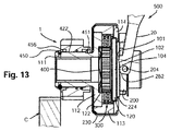
衝撃およびノイズを制限するため、本発明の他の実施形態によれば、ピニオン11がスリーブ111に対して軸方向に移動できるようにピニオン11を装着するようにする。これを達成するために、スリーブ111の外周とスリーブ111とは別個のピニオン11の内周との間に適合溝付きアセンブリ422が存在する。このアセンブリは、ピニオン11とケーシング112,113,114と一体のスリーブ111との間に開連リンクを形成する。
In order to limit shock and noise, according to another embodiment of the present invention, the
溝422は、ここでは、適合する螺旋溝28,29に対して逆の軸方向の方向性を有する。
The
ピニオン11は、軸方向に向けられる円筒壁452によって後方へ延ばされ、円筒壁452は、スリーブ111の外周と共に、弾性部材451、ここではコイルスプリング451を収容するキャビティを境界付ける。このスプリング451は、その軸方向端部のうちの一方で、壁452とピニオン11の内周との間の接続部を構成するこのキャビティの底部に当接する。スプリング451の他方の軸方向端部は、反作用プレート112の前面を支持する。
The
壁452はスプリング451をガイドする。スリーブ111の軸方向後端には、溝453が該溝をスリーブ111の外周に機械加工できるようにプレート112に隣接して設けられる。
ピニオン11の前端の内周は、ピニオン11を軸方向で保持するサークリップ(著作権)のためのハウジング456を形成するために凹陥状になっている。このサークリップは、スリーブ111の前端に機械加工される溝454内に装着される。スターター駆動ユニット1の休止位置(図12)において、スプリング451は、軸方向ストッパを備えるサークリップの方向にピニオン11を押圧し、このとき、軸方向ストッパは、ハウジング456のベースにより形成される肩部を支持する。
The inner periphery of the front end of the
ピニオン11がリングギアCに当接してリングギアに入り込まない(図13)と、スプリング451が圧縮され、ピニオン11は、衝撃およびノイズが最小限に抑えられるように、反作用プレート112の方向で後方に移動する。
If the
その結果、図1のスプリング5は、移動接点3aが端子3e,3fのヘッドと係合して電気モータMを回転させるまで圧縮され、それにより、ピニオン11が既知の方法でリングギアに入り込むことができる。
As a result, the
スプリング451の剛性は、弾性ワッシャ400の剛性よりも大きいが、スプリング5の剛性よりも小さい。
The rigidity of the
なお、図3,8,9,11において、弾性ワッシャ400は、反作用プレート112の内周の厚さの減少部分に形成される環状溝内に装着される。X軸に対して垂直に向けられる肩部がこのように形成される。この肩部は、X軸に対して軸方向に向けられる環状ベアリング部材によってその外周が境界付けられる。このベアリング部材は、これらの図において波形状を成す弾性ワッシャ400の外周のための心出しベアリング部材を構成する。
3, 8, 9, and 11, the
図4および図10は、ワッシャ400を収容する溝401の変形例を示す。この溝401は、駆動要素118の方向で軸方向に開放しており、垂直に方向付けられる底部と、2つの軸方向に向けられた平行な側面とを備える。全てのケースにおいて、反作用プレート112は、ワッシャ400を収容するためにその内周が切り欠かれており、それにより、軸方向の寸法を減少させることができる。
4 and 10 show a modification of the
変形例として、反作用プレート112は、一定の厚さを成すとともに、ワッシャ400を収容するために軸方向に向けられる円筒状の壁を有する。
As a variant, the
本発明の結果、明細書本文および図面から明らかなように、スターター駆動ユニット1が移動し始めるにつれて、ピニオン11は、それがアイドリングピニオンを構成するように両方向に回転できる。
As a result of the present invention, as is apparent from the specification and drawings, as the
機械的な同期装置がもたらされる−アイドリングピニオン11は、ピニオン11の回転速度がリングギアCの回転速度と適合して同期するようにリングギアが回転しているときにリングギアC内に入り込むことができる。リングリア内へのこの入り込みは、リングギアが逆方向に回転している場合であっても起こり得る。
A mechanical synchronizer is provided-the
2段階動作が引き起こされる。 A two-stage operation is triggered.
第1の段階において、カム形状のシュー100は、ピニオン11と少なくとも回転状態で接続されるリング114に作用する。このとき、ピニオンは、それがこの第1の段階中にアイドリングできるため、自由である。ピニオン11は、リング114を介して軸方向に移動され、したがって、このときクラッチ300は離脱されているため、抵抗なくリングギアCと係合できる。
In the first stage, the cam-shaped
ピニオン11がリングギア内に数ミリメートル入り込む(図9)と、第2の段階が起こる。無論、これは、ディスクまたはディスク301,302の厚さに依存する。
The second stage occurs when the
第2の段階では、シュー100がリング114を押圧するのを止め、また、ヨーク200は、溝223の側面224に作用して、駆動要素118およびそのフランジ120を反作用プレート112の方向に移動させ、それにより、クラッチ300が漸進的に係合され、したがって、1または複数の摩擦ディスク301,302が反作用ディスク112とフランジ120から構成される圧力プレートとに対して漸進的に締め付けられて、トルクが電気モータからヒートエンジンのスターターのスターターリングギアCへと伝えられる。漸進的な係合は、端部ディスク302とフランジ120との間に遊びが存在するように確保するワッシャ400によって促進される。
In the second stage, the
この第2の段階中、ヨーク200が径方向に移動する。ヨークは、シュー100によってスターター駆動ユニット1のケーシングに及ぼされる力に対してスターター駆動ユニット1の駆動要素118に差動的に作用する。
During this second stage, the
クラッチ300は、従来の摩擦クラッチスターターよりも速く係合する。ディスク301,302は圧縮中に一緒に保持される。
The clutch 300 engages faster than a conventional friction clutch starter.
クラッチは離脱できず、クラッチ内の圧力はヨーク20により維持される。また、ヨークが溝233内に装着されるため、クラッチ300が更に急速に閉じる。
The clutch cannot be disengaged, and the pressure in the clutch is maintained by the
発明の結果、ヒートエンジンのための再始動時間、衝撃、および、ノイズが減少される。ヒートエンジンの2回の連続する再始動間の時間を減らすことができる。 As a result of the invention, restart time, shock and noise for the heat engine are reduced. The time between two successive restarts of the heat engine can be reduced.
これに関しては、グラフA,B,Cの縦座標Nがヒートエンジンの回転速度(回転/分)に対応し且つ横座標tが時間に対応する図15についても参照されたい。 In this regard, see also FIG. 15 where the ordinate N of graphs A, B, C corresponds to the rotational speed (rotations / minute) of the heat engine and the abscissa t corresponds to time.
この図15において、参照符号Rはヒートエンジンのアイドリング状態に対応し、これは、ディーゼルエンジンに関しては、全体として750rpm程度であり、参照符号Mは、ヒートエンジン(独立の走行状態)における最小再始動回転速度に対応し、また、長方形D,E,Cは、グラフの一部を取り囲む異なるウインドウに対応する。 In FIG. 15, reference symbol R corresponds to the idling state of the heat engine, which is about 750 rpm as a whole for the diesel engine, and reference symbol M is the minimum restart in the heat engine (independent running state). Corresponding to the rotational speed, the rectangles D, E, C correspond to different windows surrounding a part of the graph.
グラフAは、ヒートエンジンが停止されるときのヒートエンジンにおける前述した従来のグラフに対応する。 Graph A corresponds to the above-described conventional graph in the heat engine when the heat engine is stopped.
この場合、回転速度が減少し(ウインドウD)、また、序文で説明したように、特にヒートエンジンのピストンが特定の位置にある状態でヒートエンジンが完全に停止する前に1つ以上のピストンが降下する際の逆回転に起因して、振動減少および変動減少が起こる(ウインドウE)。 In this case, the rotational speed is reduced (window D) and, as explained in the introduction, the one or more pistons must be stopped before the heat engine is completely stopped, especially with the heat engine piston in a particular position. Due to the reverse rotation when descending, vibration reduction and fluctuation reduction occur (window E).
通常、欧州特許第146264号明細書に記載されるように、ウインドウFに含まれる特性グラフにしたがってヒートエンジンを再始動できる前にヒートエンジンが完全に停止されるまで待つことが必要である。グラフBは、ウインドウEに含まれる第1の振動が延長される特徴的な再始動グラフに対応する。 Normally, it is necessary to wait until the heat engine is completely stopped before it can be restarted according to the characteristic graph contained in the window F, as described in EP 146264. Graph B corresponds to a characteristic restart graph in which the first vibration included in window E is extended.
ヒートエンジンは、それがウインドウEにおけるプラスの回転速度へ変化した後にグラフBに基づいて再始動させることができる。このグラフBは、時間に関してグラフFに対するオフセットである。グラフBは、時間においてグラフFに先行する。無論、ヒートエンジンをウインドウD内で再始動させることができる。 The heat engine can be restarted based on graph B after it has changed to a positive rotational speed in window E. This graph B is an offset to the graph F with respect to time. Graph B precedes Graph F in time. Of course, the heat engine can be restarted in window D.
本発明のおかげにより、ヒートエンジンが完全に停止するのを待つ必要がない。 Thanks to the present invention, there is no need to wait for the heat engine to stop completely.
実際に、前述した態様で、ピニオン11は、このウインドウE内でリングギアC内に入り込むことができる。また、ピニオンは、それが依然としてウインドウD内で回転しているときにリングギアCに入り込むこともできる。
Actually, the
再始動時間が短くされ、また、機械的なシステムを使用して再始動時間が短くされるのが分かる。 It can be seen that the restart time is shortened and the restart time is shortened using a mechanical system.
無論、本発明は、前述した実施形態に限定されない。 Of course, the present invention is not limited to the embodiment described above.
したがって、変形例として、ブシュ124は、図14に見られるよう、2つのニードルローラベアリング124’と置き換えられる。
変形例として、ブシュ124は、潤滑ベアリングと置き換えられ、また、ニードルローラベアリングなどの他のベアリングと置き換えられる。
Thus, as a variant, the
As a variant, the
スリーブ111の存在は必須ではない。
The presence of the
フランジ120は、リング114において内側凹部115,215の必要性がないようにリング114の前面と直接に当接してもよい。
The
スカート113は、1つの変形例では、ピニオン11から離れる方向で軸方向後方へ延ばされる。このスカート113は、フランジ120のためのストッパ肩部を形成するサークリップなどのリングまたは他の構成を内部で支持する。この場合、突出シュー100は、スカート113の自由端を支持するようになっている。この軸方向の延長は、例えば、その外径が更に小さい先の図における閉塞リング114の厚さに少なくとも等しい。
In one variation, the
スカート113の軸方向の延長は、側面224の厚さのように、更に増大されてもよい。したがって、スカート113の自由端に直径の変化が与えられて、そのスカートの厚さが減少され、シュー100のための環状の支持肩部が形成されてもよい。
The axial extension of the
したがって、レバー20は、そのシュー100により、閉塞肩部を内部で支持するスカート113の自由端に対してピニオン11の方向に軸方向でオフセットされる環状肩部に当接できる。
Therefore, the
全ての状況において、シュー100は、ケーシングに作用して、反作用プレート112およびスカート113を押圧する。
In all situations, the
変形例として、クラッチと係合するための手段は、更なるレバー120Aと関連付けられる係合部品200Aを含む。
Alternatively, the means for engaging the clutch includes an
この場合、移動アセンブリ500には、図16および図17に見られるように、制御レバー20と更なるレバー12Aとを備えるダブルレバーが設けられる。
In this case, the moving
レバー20は、図3〜図13の場合と同様にケーシングを移動させるようになっており、一方、更なるレバー120Aは、更なるレバー120Aの下端に関節によって取り付けられる係合部材200Aを介して、クラッチの圧力要素を移動させるようになっている。
The
この更なるレバー120Aは、制御レバー20を該制御レバーの上端と下端との間で連結態様により装着可能に後述する態様で構成される。
The
円柱状の旋回軸20bは更なるレバー120Aに属する。
The
この更なるレバー120Aは2つの部分1210,1220を備え、これらの各部分が旋回軸20bを支持する。
This
これらの部分1210,1220は、この更なるレバー120Aの上端と下端との間に関節によってレバー20を装着する円柱状の支柱1200によって互いに接続される。
These
支柱1200は、制御レバー20のための中間関節軸を間接的に構成する旋回軸20bの延長部に組み込まれる。
The
図6および図7の場合と同様に、ケーシングの移動を制御するレバー20は、上端244〜246と、フォーク形状下端240〜242と、レバーの上端を下端に接続する接続部243とを有する。
6 and 7, the
このレバー20の上側部分は、図6に示される上側部分と比べて変わらず、したがって、図1のロッド5aの通過のためのスロット246により互いから離間している2つの突起244,245を備える。各突起244,245は軸20aを受けるために凹部247を備える。
The upper part of this
レバーの下側部分は、図6の下側部分と同様であり、したがって、接続部243に接続する丸みを帯びた部分242によって接続される2つのアーム240,241を備える。各アームはシュー100を有する。
The lower part of the lever is similar to the lower part of FIG. 6 and thus comprises two
下端240〜242は穴を何ら含まない。これは、クラッチの係合部材200Aが更なるレバーレバー120Aの下端に関節接続されるからである。
The lower ends 240 to 242 do not include any holes. This is because the
接続部243は図6の接続部と同様である。違いは、この部分が円柱状の支柱1200に連結装着するための溝1200Aを含むという事実にある。
The
溝1200Aは、それが支柱1200にスナップ嵌合できるように開放する。溝1200Aのサイズは、接続部243、したがって、レバー20を支柱1200に連結装着できるように支柱1200の外径と適合する
The
レバー120Aの2つの部分1210,1220はフランジを備える。各フランジ1210,1220は、下端と、上端と、下端と上端との間の接続部1243とを有する。
The two
したがって、更なるレバー120Aは、円柱状の関節支柱1200によって離間している2つの部分の接続部1243を備え、関節支柱1200はこれらの2つの部分間の距離を設定する。1つの特徴によれば、レバー20の接続部243は、支柱1200の位置におけるレバー120Aの2つの接続部間の距離がレバー20の接続部243の厚さに依存するように、更なるレバー120Aの接続部1243の2つの部分間に位置する。レバー120Aの接続部1243の2つの部分と制御レバー20の接続部243の節間接続部との間には組み付け遊びが存在する。
Thus, the
各フランジ1210,1220の上端は、支軸20bを支持する接続部1243に対してオフセットされる突起1244,1245を備える。突起1244,1245にはそれぞれ、軸20aの対応する端部が入り込む楕円形の穴1247が設けられる。
The upper ends of the
各フランジの下端はそれぞれアーム1240,1241を備える。各アーム1240,1241は、クラッチ300の係合部材200Aの軸200Bを受けるために穴(参照符号を付さない)を備える。この部品200Aは、弓形状であり、その先端のそれぞれで弓を支える軸200Bによってアーム1240,1241間に連結装着される。弓200Aは、半円形状を成し、したがって、全体として周方向に180°にわたって延びる。
The lower end of each flange is provided with
シュー100およびアーム240,241は軸200Bの上側で延びる。なお、更なるレバー120Aは、その下端に、アーム1240,1241間の接続部を有さない。
The
レバー20は更なるレバー120A内に位置され、アーム1240,1241はアーム240,241の形状と適合し、一方、突起1244,1245は突起244,245のそれぞれと平行である。接続部243は接続部1243内に収容される。無論、組み付け遊びが存在する。
The
したがって、制御レバー20は、更なるレバー120A内にその下端と上端との間で支柱により回動するように重なり合って装着される。
Therefore, the
最初に、ロッド5aが軸20aを移動させ、そのため、レバー20は、支柱1200Aを中心に回動して、シュー100を介してケーシングに作用し、図3〜図13の場合と同様にピニオン11を移動させる。
First, the
軸20aの先端と穴1247との間に存在する遊びがなくなった後、更なるレバー120Aが動作されて図1および図2の支持部36において旋回軸20bにより回動する。
After the play that exists between the tip of the
その後、係合部材200Aは、側面224に作用して、図3〜図13の場合と同様にクラッチ300を締め付けるために駆動要素118を移動させる。係合部材200Aは、軸20aと穴1247の前縁との間の遊びをなくした後にレバー120Aを介して遅延をもって作用する。したがって、この部材200Aは、レバー20の後に遅延をもって作用するように構成される更なるレバー120Aの下端に連結態様で取り付けられる。
Thereafter, the
この実施形態において、クラッチと係合するための手段は、旋回軸20bにより回動する更なるレバー120Aを備え、この更なるレバーの一方の部分は、スターターの一部を形成する操作手段20a,5aによって遊びがなくなった後に移動され得る上端1244,1245を備え、更なるレバーの他方の部分は、駆動要素118を介してクラッチの圧力要素を軸方向に移動させるとともに駆動要素118を反作用プレートの方向に押圧してクラッチ300を締め付けるために遅延態様で駆動要素118に作用し得る係合部材200Aを連結装着するように構成される2つのアーム1240,1241を備える下端を備える。更なるレバー120Aを動作させるための手段は、制御レバー20を動作させるための手段を備える。
In this embodiment, the means for engaging the clutch comprises a
以上から分かるように、更なるレバー120Aは2つのフランジ1210,1220を備え、これらのフランジは、2つのフランジ1210,1220間に位置する制御レバー20の形状に適合する。これらの2つのフランジ1210,1220は、制御レバー20のための連結装着を行なう円柱状の支柱1200によってそれらの下端同士および上端同士の間が互いに離間している。
As can be seen, the
レバー20,120Aはプラスチック材料から成ってもよい。
The
フランジ1220,1210は、支柱1200および旋回軸20bと一体を成してもよい。
The
レバー20が金属から成ってもよく、また、レバー120Aがプラスチック材料から成ってもよい。
The
支柱1200は、フランジ1220,1210と一体を成してもよく、或いは、フランジ1210,1220に取り付けられてもよい。
The
全てのケースにおいて、シュー100は、レバー20と一体を成してもよく、或いは、レバー20に取り付けられてもよい。
In all cases, the
変形例として、構造が逆にされてもよい。つまり、変形例において、シュー100がスターター駆動ユニット1のケーシングに支持されてもよい。このとき、これらのシュー100はそれぞれ、制御レバー20の対応するアームと共に作用する。
As a variant, the structure may be reversed. That is, in a modification, the
シューは、状況にしたがって、閉塞リング114またはスカート113に属する。
The shoe belongs to the
前述した実施形態においては、制御レバー20と摩擦クラッチ300の係合手段200−200A,120Aと間に関節手段が存在する。
In the embodiment described above, joint means exist between the
図3〜図13において、これらの手段は穴261および旋回軸204を備え、また、図16および図18において、これらの手段は、軸200Bおよびこれらの軸を受けてアーム1240,1241に形成される穴と共に、溝1200Aおよび支柱1200を備える。変形例として、アーム1240,1241は、係合部材の穴内に受けられる軸200Bを有する。
3 to 13, these means include a
摩擦クラッチ300は、前述したように、2006/100353号に記載されるような円錐台タイプの変形例である。
As described above, the
したがって、1または複数の摩擦ディスクは、変形例において、円錐台の外周を有する摩擦ライニングに取って代えられ、この摩擦ライニングは、スターター駆動ユニットの前部に固定される摩擦要素を備えるとともに、摩擦ライニングの外周と共に作用するために円錐台形状の内周の反作用プレート上の隆起部に取り付けられるキャップの一部を形成するスカートと一体を成す閉塞リングを通過する圧力要素を備える。このスカートと一体を成す保持リングは、好適には、補強されるべくリブが付けられる。 Thus, the one or more friction discs are replaced in a variant by a friction lining having a frustoconical perimeter, the friction lining comprising a friction element fixed to the front of the starter drive unit and the friction lining. A pressure element is provided that passes through a closure ring integral with a skirt that forms part of a cap that is attached to a ridge on a frustoconical inner reaction plate to act with the outer periphery of the lining. The retaining ring integral with the skirt is preferably ribbed to be reinforced.
反作用プレートの外側隆起部は、変形例では、スカートを構成するために軸方向後方へ延ばされ、スカートの自由端には、クラッチの閉塞リングが取り付けられる。このとき、反作用プレートの垂直部分に形成される環状溝内に装着される弾性ワッシャ400は、休止状態で保持リングに当接する摩擦ライニングを取り外すことができるようにする。スターター駆動ユニットは、プラスチック材料から成ってもよく、係合ヨークおよび保持リングを受ける溝を備える。摩擦要素には、繊維強化プラスチック材料が充填されてもよい。
The outer ridge of the reaction plate, in a variant, extends axially rearward to form a skirt, and a clutch closure ring is attached to the free end of the skirt. At this time, the
したがって、摩擦要素は、全てのケースにおいて、閉塞リングにより画定されるケーシング内に少なくとも部分的に収容される。 The friction element is thus at least partially housed in the casing defined by the closure ring in all cases.
したがって、摩擦ディスクは、図3〜図13の場合にように前面がその後面と平行な状態でX軸に対して垂直に方向付けられてもよい。この場合、これらの前面および後面のうちの少なくとも一方は、クラッチ300の摩擦面を構成する。変形例において、摩擦面は、摩擦ライニングの外周を備えてもよい。 Thus, the friction disk may be oriented perpendicular to the X axis with the front face parallel to the rear face as in FIGS. In this case, at least one of these front and rear surfaces forms a friction surface of the clutch 300. In a variant, the friction surface may comprise the outer periphery of a friction lining.
本発明は、ヒートエンジンにおいて通常の全てのタイプのスターターに適用される。 The present invention applies to all types of starters that are common in heat engines.
したがって、スターター駆動ユニットのピニオンは、仏国特許第2677710号明細書、米国特許第4895035号明細書、および、仏国特許第2738599号明細書に記載されるように、前側ベアリングを通過してもよく、また、ケーシングを越えて延びてもよい。 Thus, the starter drive unit pinion can pass through the front bearing as described in French Patent No. 2677710, US Pat. No. 4,895,035, and French Patent No. 2,738,599. It may also extend beyond the casing.
この場合、これらの文献に見られるように、スリーブ111が延ばされ、また、スリーブの外周とケーシングとの間にボールベアリングなどのベアリング手段が径方向に配置されている。ストッパ25がシャフト24の自由端に取り付けられてもよく、或いは、ストッパ25がシャフト24の自由端の近傍に組み込まれてもよい。
In this case, as can be seen in these documents, the
スターター駆動ユニットのピニオンは、前述した態様で、図1の場合のように外側に歯が付けられる或いは仏国特許第2858366号明細書の場合のように内側に歯が付けられるスターターリングギアと係合してもよい。変形例として、仏国特許第2858366号明細書に記載される動作の伝達は、クランクシャフトと一体を成す歯車とスターターの一部を形成して内歯付きスターターリングギアと一体を成す歯車との間のチェーン伝達と置き換えられてもよい。変形例として、ギア伝達は、クランクシャフトと一体を成す歯車とスターターの一部を形成してスターター駆動ユニットと係合できるスターターリングギアと一体を成す歯車との間に位置されてもよい。全てのケースにおいて、スターターリングギアCは、このヒートエンジンのクランクシャフトに対して直接的に或いは間接的に接続される。 The pinion of the starter drive unit is associated with a starter ring gear which is toothed on the outside as in the case of FIG. 1 or toothed on the inside as in French patent 2858366 in the manner described above. May be combined. As a variant, the transmission of motion described in French Patent No. 2858366 is performed between a gear that is integral with the crankshaft and a gear that is part of the starter and is integral with the starter ring gear with internal teeth. It may be replaced with chain transmission between. As a variant, the gear transmission may be located between a gear integral with the crankshaft and a gear integral with a starter ring gear which forms part of the starter and can be engaged with the starter drive unit. In all cases, the starter ring gear C is connected directly or indirectly to the crankshaft of this heat engine.
前述したように、スターターの出力シャフトは、電気モータの出力シャフトと同じであってもよく、或いは、電気モータの出力シャフトとは別個であってもよく、また、2つの出力シャフトが同軸であってもよく或いはオフセットしていてもよい。 As described above, the output shaft of the starter may be the same as the output shaft of the electric motor, or may be separate from the output shaft of the electric motor, and the two output shafts are coaxial. Or may be offset.
仏国特許第2858366号明細書に記載されるように、2つの減速ギア、すなわち、遊星歯車トレインタイプの2つの減速ギアが設けられてもよい。 As described in French Patent No. 2858366, two reduction gears, ie two reduction gears of the planetary gear train type, may be provided.
例えば仏国特許第2803345号明細書に記載されるように、トルクリミッタおよび/またはトーションダンパーが減速ギアと関連付けられてもよい。 For example, a torque limiter and / or a torsion damper may be associated with a reduction gear as described in French Patent No. 2803345.
制御レバーは、好ましくはプラスチック材料製のベアリングの旋回軸に装着されてもよく、このベアリングは、国際公開第01/31195号パンフレットに記載されるように、ケーシングの前側ベアリングにより支持される第1のベアリング部分と、作動要素の前部と共に作用する垂直環状リングを備えるレバーの支持部品に適合して形成される第2の相補的部分とを備える。 The control lever may be mounted on the pivot of a bearing, preferably made of plastic material, which bearing is supported by a first bearing supported by the front bearing of the casing, as described in WO 01/31195. And a second complementary part formed in conformity with the support part of the lever comprising a vertical annular ring acting with the front part of the actuating element.
変形例として、レバーは、国際公開第2005/054664号パンフレットに記載されるように、レバー関節機能を確保するように形成される減速ギアの歯付きリングギアの延長部に回動可能に装着されてもよい。 As a modification, the lever is rotatably mounted on an extension of a toothed ring gear of a reduction gear formed to ensure the lever joint function, as described in WO 2005/054664. May be.
前述した国際公開第2005/054664号パンフレット、仏国特許第2631094号明細書、および、仏国特許第2858366号明細書の場合のように、タイロッドがケーシングの後側ベクトルを前側ベアリングに組み付け、それにより、これらのベアリング間のブシュを締め付けてもよい。 As in the case of the above-mentioned WO 2005/054664 pamphlet, French Patent No. 2631094, and French Patent No. 2858366, the tie rod assembles the rear vector of the casing to the front bearing, Thus, the bush between these bearings may be tightened.
電気モータのステータは、国際公開第98/329966号パンフレットの場合のように巻線を備えてもよく、または、永久磁石を備えてもよい。 The stator of the electric motor may be provided with windings as in WO 98/329966 or may be provided with permanent magnets.
例えば仏国特許第2934434号明細書に記載されるように、特に、燃料消費量を減らすために、交通状態に起因して、例えば、赤信号または交通渋滞で停止するときに、ヒートエンジンを停止させて、その後に、ヒートエンジンを再始動させることができるようにするストップ&スタート機能をスターターが果たさなければならないときには、ブラシの数が増大されてもよい。 For example, as described in French Patent No. 2934434, to reduce fuel consumption, stop the heat engine due to traffic conditions, for example when stopping at a red light or traffic jam The number of brushes may be increased when the starter must perform a stop and start function that allows the heat engine to be restarted thereafter.
図1の場合のように、コンタクタがスターターの電気モータの上側に位置されてもよく、或いは、コンタクタは、スターターの電気モータから離れて位置され、例えば、仏国特許第2843427(A)号明細書に記載されるように、戻し機構を介してスターターの電気モータの背後に垂直に装着されてもよい。 As in the case of FIG. 1, the contactor may be located above the starter electric motor, or the contactor may be located away from the starter electric motor, eg, French Patent No. 2844327 (A). It may be mounted vertically behind the starter's electric motor via a return mechanism, as described in the document.
国際公開第98/32966号パンフレットに照らして、コンタクタがホールドインコイルおよびプルインコイルを備えてもよいことが分かる。 In light of WO 98/32966, it can be seen that the contactor may comprise a hold-in coil and a pull-in coil.
変形例として、コンタクタは、FR A 2 795 884仏国特許第2795884(A)号明細書に記載されるように、1つのコイルのみを有する。
As a variant, the contactor has only one coil, as described in
変形例として、移動接点3aの後面のための支持肩部は、他の形状を成してもよく、また、例えば、特にスターターがストップ&スタート機能を果たさなければならないときには、仏国特許第2895143号明細書に記載されるようなバヨネットタイプのアセンブリに属してもよく、或いは、仏国特許第2767960号明細書に記載されるようなコンタクタ3aの中心開口とロッド3との間のスナップフィットアセンブリに属してもよい。 As a variant, the support shoulder for the rear face of the moving contact 3a may take other shapes, for example when the starter has to perform a stop-and-start function, FR 2895143. A snap-fit assembly between the central opening of the contactor 3a and the rod 3 as described in French Patent No. 2767960 It may belong to.
バヨネットタイプのアセンブリは係合ヨーク200に適合されてもよい。この場合、側面224と反対側の溝223の他方側は、ヨーク200の通過のための2つの平坦面を備えてもよく、ヨーク200は2つの適合する平坦面を備え、そのため、ヨークが溝223の底部内で回転し、ヨークの2つの平坦面間の距離は、溝の底部の外径によって決まる。これは側面224にも適用される。
The bayonet type assembly may be adapted to the
変形例として、制御レバーを操作するための手段は、制御レバーを操作するための移動コア電磁コンタクタと、制御ロッドおよび移動アセンブリを制御するための他の電磁コンタクタとを備えてもよい。 As a variant, the means for operating the control lever may comprise a moving core electromagnetic contactor for operating the control lever and other electromagnetic contactors for controlling the control rod and the moving assembly.
変形例として、制御レバーを操作するための手段は、例えばラックタイプの機械的なリンク機構を介して移動コアに作用する電気モータドライブを備えてもよく、移動コアは、その内部に、図1の場合のようなロッドに取り付けられる歯間押し付けスプリングを備える。 As a variant, the means for operating the control lever may comprise, for example, an electric motor drive acting on the moving core via a rack-type mechanical linkage, the moving core being located in FIG. The interdental pressing spring is attached to the rod as in the case of.
ヒートエンジンは、セダン型乗用車またはボートなどの原動機付き車両に固定されてもよく、或いは、該原動機付き車両の一部であってもよい。 The heat engine may be fixed to a motorized vehicle such as a sedan-type passenger car or a boat, or may be a part of the motorized vehicle.
Claims (27)
−前記スターター歯付きリングギアに噛み合うためのピニオン(11)と軸方向対称軸(X)とが設けられたスターター駆動ユニット(1)と、
−前記スターター駆動ユニット(1)の一部を形成する駆動要素(118)と、
−前記駆動要素(118)と前記ピニオン(11)との間に位置する摩擦クラッチ(300)であって、前記クラッチには、反作用プレート(112)と、前記駆動要素(118)と一体を成す圧力要素(118,120)と、前記反作用プレート(112)と前記圧力要素(118,120)との間で締め付けられ得る少なくとも1つの摩擦要素(301)とが設けられた、摩擦クラッチ(300)と、
を備え、
−前記圧力要素(118,120)は、少なくとも一部がケーシング(112,113,114)内に位置され、前記ケーシングの一方の部分は、前記ピニオン(11)と一体して回転し、前記ケーシングの他方の部分は、前記摩擦クラッチ(300)の前記反作用プレートを備えるプレート(112)を備えており、
−スターター(4)の一部を形成する操作手段(2)によって移動され得る上端(244,245)を一方の部分に備えるとともに、前記スターター駆動ユニット(1)に作用するための2つのアーム(240,241)を備えるフォーク形状の下端(240〜241)を他方の部分に備える、回動制御レバー(20)
を備え、
前記制御レバー(20)は、前記摩擦クラッチ(300)のための係合手段(200−200A,120A)と関連付けられ、
−関節手段は、前記制御レバー(20)と前記摩擦クラッチ(300)の前記係合手段(200−200A,120A)との間に位置され、
−前記制御レバー(20)は、前記ケーシング(112,113,114)が前記スターターリングギア(C)に噛み合う前記前進位置へ向けて前記軸方向対称軸(X)に沿って軸方向に最初に移動可能に構成され、一方、前記摩擦クラッチ(300)の前記係合手段200−200A,120A)は、次に前記摩擦クラッチ(300)を締め付けるためにこれらの係合手段が前記駆動要素(118)を前記反作用プレート(112)の方向で軸方向に移動させるように構成される、
ことを特徴とする移動スターター駆動ユニット(1)/制御レバー(20)アセンブリ(500)。 With a moving starter drive unit (1) / control lever (20) assembly (500) movable between a retracted rest position and an advanced position for meshing with a starter toothed ring gear (C) of some heat engines There,
A starter drive unit (1) provided with a pinion (11) and an axially symmetrical axis (X) for meshing with said starter toothed ring gear;
A drive element (118) forming part of the starter drive unit (1);
A friction clutch (300) located between the drive element (118) and the pinion (11), wherein the clutch is integral with the reaction plate (112) and the drive element (118); A friction clutch (300) provided with a pressure element (118, 120) and at least one friction element (301) that can be clamped between the reaction plate (112) and the pressure element (118, 120) When,
With
The pressure element (118, 120) is at least partially located in the casing (112, 113, 114), one part of the casing rotating integrally with the pinion (11), The other part of the plate comprises a plate (112) comprising the reaction plate of the friction clutch (300),
An upper end (244, 245) which can be moved by operating means (2) forming part of the starter (4) in one part, and two arms for acting on the starter drive unit (1) ( 240, 241) fork-shaped lower end (240-241) on the other part, rotation control lever (20)
With
The control lever (20) is associated with engagement means (200-200A, 120A) for the friction clutch (300);
The joint means is located between the control lever (20) and the engagement means (200-200A, 120A) of the friction clutch (300);
The control lever (20) is initially axially along the axially symmetric axis (X) towards the forward position where the casing (112, 113, 114) meshes with the starter ring gear (C); The engagement means 200-200A, 120A) of the friction clutch (300) are then configured to be movable so that these engagement means are then used to tighten the friction clutch (300). ) In the axial direction in the direction of the reaction plate (112),
A moving starter drive unit (1) / control lever (20) assembly (500) characterized in that.
閉塞リング(114)と、
前記反作用プレート(112)を前記閉塞リング(114)に接続するスカート(113)と、
を備え、
カム(101,102,103)の形態を成す前記各突出シュー(100)は、前記ケーシング(112,113,114)の前記閉塞リング(114)と接触するように構成されることを特徴とする請求項1、請求項2、および、請求項2と組み合わされる請求項5から7のいずれか一項に記載の移動アセンブリ。 The casing (112, 113, 114)
An occlusion ring (114);
A skirt (113) connecting the reaction plate (112) to the closure ring (114);
With
Each protruding shoe (100) in the form of a cam (101, 102, 103) is configured to contact the closing ring (114) of the casing (112, 113, 114). 8. A moving assembly according to any one of claims 1, 2, and 5 to 7 combined with claim 2.
カム(101,102,103)の形態を成す前記各突出シュー(100)は、前記ケーシング(112,113)の前記スカート(113)と接触するように構成されることを特徴とする請求項1、請求項2、および、請求項2と組み合わされる請求項5から7のいずれか一項に記載の移動アセンブリ。 The casing (112, 113) has a connecting skirt (113) extending to the outer periphery of the reaction plate (112) oriented in the opposite direction to the pinion (11),
Each said protruding shoe (100) in the form of a cam (101, 102, 103) is configured to contact the skirt (113) of the casing (112, 113). A transfer assembly according to any one of claims 5 to 7, in combination with claim 2, and claim 2.
前記各頂点部分(101)は、前記丸みを帯びた部分(262)に取り付けられる平坦部(104)の方向に延びる傾斜部分(102)によってその内周が延ばされることを特徴とする請求項10に記載の移動アセンブリ。 A lower end of the arm (240, 241) of the control lever (20) has a rounded portion (262);
11. The inner circumference of each of the apex portions (101) is extended by an inclined portion (102) extending in the direction of a flat portion (104) attached to the rounded portion (262). A moving assembly as described in.
前記係合ヨーク(200)は、少なくとも1つの外側部分(203)を介して互いに接続される2つの分岐部(201,202)を備えることを特徴とする請求項14に記載の移動アセンブリ。 The opening of the engagement yoke (200) has an oval shape to allow radial movement of the engagement yoke (200) relative to the groove (223),
15. A moving assembly according to claim 14, wherein the engagement yoke (200) comprises two branches (201, 202) connected to each other via at least one outer part (203).
前記溝(223)は前記駆動ブシュ(119)に取り付けられる環状部材(123)によって形成されることを特徴とする請求項19に記載の移動アセンブリ。 The precursor drive element (118) comprises a drive bush (119);
20. A moving assembly according to claim 19, wherein the groove (223) is formed by an annular member (123) attached to the drive bushing (119).
前記駆動要素(118)を前記引き込み休止位置へと押し戻すために、軸方向に作用する弾性ワッシャ(400)は、前記反作用プレート(112)と前記駆動要素(118)との間に配置されていることを特徴とする請求項1から20のいずれか一項に記載の移動アセンブリ。 In the retracted rest position there is axial play (J) in the friction clutch (300),
An axially acting elastic washer (400) is disposed between the reaction plate (112) and the drive element (118) to push the drive element (118) back to the retracted rest position. 21. A moving assembly according to any one of the preceding claims, characterized in that
前記側面(224)が軸方向遊び(J)よりも大きい厚さを有することを特徴とする、請求項14と組み合わされる請求項21に記載の移動アセンブリ。 The engagement yoke (200) can abut against one of the side surfaces (224) of the annular groove (223) in two diametrically opposite regions;
The moving assembly according to claim 21, in combination with claim 14, characterized in that the side surface (224) has a thickness greater than the axial play (J).
前記圧力プレートは、前記駆動要素(118)と一体を成すフランジ(120)を備えることを特徴とする請求項1から23のいずれか一項に記載の移動アセンブリ。 The friction clutch (300) is in the form of a friction disk (301) positioned between the pressure element (120) in the form of a pressure plate (120) integral with the drive element (118) and the reaction plate (112). Having at least one friction element (301) comprising:
24. A moving assembly according to any preceding claim, wherein the pressure plate comprises a flange (120) integral with the drive element (118).
あるいは、前記ケーシング(112,113,114)の前記スカート(113)を介して軸方向可動性をもって前記反作用プレート(112)と一体して回転する3つの摩擦ディスク(302)、
を備えることを特徴とする請求項25または請求項26に記載の移動アセンブリ。 The friction clutch (300) has two friction disks (301) having axial movability and rotating integrally with the front part (121) of the drive element,
Alternatively, three friction disks (302) that rotate integrally with the reaction plate (112) with axial mobility through the skirt (113) of the casing (112, 113, 114),
27. A moving assembly according to claim 25 or claim 26, comprising:
電気モータ(M)により回転駆動され得る出力シャフト(24)と、
引き込み休止位置と前記ヒートエンジンのスターター歯付きリングギアに係合する前進位置との間で移動可能に前記出力シャフト(24)に装着されるスターター駆動ユニット(1)と、
を備え、
前記スターター駆動ユニット(1)は請求項1から26のいずれか一項に記載の移動アセンブリの一部を形成することを特徴とするスターター(4)。 A starter (4) for a heat engine, in particular an automobile heat engine,
An output shaft (24) that can be rotationally driven by an electric motor (M);
A starter drive unit (1) mounted on the output shaft (24) movably between a retracting rest position and a forward position engaged with a starter toothed ring gear of the heat engine;
With
Starter (4), characterized in that the starter drive unit (1) forms part of a moving assembly according to any one of claims 1 to 26.
Applications Claiming Priority (3)
| Application Number | Priority Date | Filing Date | Title |
|---|---|---|---|
| FR1156805A FR2978500B1 (en) | 2011-07-26 | 2011-07-26 | LAUNCHER MOBILE ASSEMBLY - GEAR CONTROL LEVER WITH A STARTING CROWN OF A THERMAL MOTOR AND STARTER OF A THERMAL MOTOR COMPRISING SUCH AN ASSEMBLY |
| FR1156805 | 2011-07-26 | ||
| PCT/FR2012/051746 WO2013014385A2 (en) | 2011-07-26 | 2012-07-23 | Mobile assembly comprising a starter drive unit and a control lever, for meshing with a starter ring gear of a heat engine, and a heat engine starter comprising such an assembly |
Publications (2)
| Publication Number | Publication Date |
|---|---|
| JP2014521893A true JP2014521893A (en) | 2014-08-28 |
| JP2014521893A5 JP2014521893A5 (en) | 2015-06-18 |
Family
ID=46724511
Family Applications (1)
| Application Number | Title | Priority Date | Filing Date |
|---|---|---|---|
| JP2014522140A Pending JP2014521893A (en) | 2011-07-26 | 2012-07-23 | A moving assembly comprising a starter drive unit and a control lever for meshing with a starter ring gear of a heat engine, and a heat engine starter comprising such an assembly |
Country Status (9)
| Country | Link |
|---|---|
| US (1) | US20140245984A1 (en) |
| EP (1) | EP2737199A2 (en) |
| JP (1) | JP2014521893A (en) |
| KR (1) | KR20140051916A (en) |
| CN (1) | CN103717879A (en) |
| BR (1) | BR112013033469A2 (en) |
| FR (1) | FR2978500B1 (en) |
| RU (1) | RU2014107016A (en) |
| WO (1) | WO2013014385A2 (en) |
Families Citing this family (26)
| Publication number | Priority date | Publication date | Assignee | Title |
|---|---|---|---|---|
| FR3003307A1 (en) * | 2013-03-13 | 2014-09-19 | Valeo Equip Electr Moteur | STARTER STARTER HAVING A FRICTION CLUTCH WITH DOUBLE CONTROL LEVERS |
| FR3004222B1 (en) | 2013-04-08 | 2017-08-11 | Valeo Equip Electr Moteur | IMPROVED PENCIL ASSEMBLY, LAUNCHER, AND STARTER FOR CORRESPONDING MOTOR VEHICLE |
| FR3004497B1 (en) | 2013-04-10 | 2015-03-27 | Valeo Equip Electr Moteur | LAUNCHER STARTER WITH AN INTERMEDIATE FRICTION REDUCTION ELEMENT BETWEEN A CONTROL LEVER AND A TRAINER |
| FR3004496B1 (en) | 2013-04-15 | 2017-08-11 | Valeo Equip Electr Moteur | CROWN WITH INSERT FOR SPEED REDUCER OF A THERMAL MOTOR STARTER AND CORRESPONDING SPEED REDUCER ASSEMBLY. |
| JP6105399B2 (en) * | 2013-06-07 | 2017-03-29 | トヨタ自動車株式会社 | Control device for internal combustion engine |
| FR3012547B1 (en) * | 2013-10-28 | 2015-11-13 | Valeo Equip Electr Moteur | IMPROVED FRICTION CLUTCH LAUNCHER AND MOTOR VEHICLE THERMAL MOTOR STARTER CORRESPONDING |
| FR3013532B1 (en) | 2013-11-18 | 2017-07-21 | Valeo Equip Electr Moteur | MOTOR VEHICLE STARTER OF LOW POWER AT OPTIMIZED SIZE |
| FR3013396A1 (en) | 2013-11-21 | 2015-05-22 | Valeo Equip Electr Moteur | STARTER MOTOR THERMAL MOTOR STARTER LAUNCHER AND STARTER COMPRISING SUCH LAUNCHER |
| FR3015799B1 (en) | 2013-12-20 | 2016-12-30 | Valeo Equip Electr Moteur | MOTOR VEHICLE MOTOR MOTOR STARTER HAVING AN IMPROVED POLISHED INDUCTOR ELECTRICAL ROTATING MACHINE AND CORRESPONDING POLAR MASS |
| JP2015137602A (en) * | 2014-01-23 | 2015-07-30 | 株式会社デンソー | starter |
| JP2015165114A (en) * | 2014-03-03 | 2015-09-17 | 株式会社デンソー | starter |
| FR3019234B1 (en) * | 2014-03-28 | 2016-03-11 | Valeo Equip Electr Moteur | STARTER LAUNCHER WITH COVER LIMITING WEAR |
| FR3022594B1 (en) * | 2014-06-24 | 2019-06-07 | Valeo Equipements Electriques Moteur | MOTOR VEHICLE STARTER |
| DE102014213097B4 (en) * | 2014-07-07 | 2016-04-07 | Schaeffler Technologies AG & Co. KG | Gimbal unit with a rotation axis for a friction clutch |
| CN105626344B (en) | 2014-10-27 | 2019-10-18 | 法雷奥电机设备公司 | Motor vehicles combustion engine starter with air ventilation holes |
| FR3027967B1 (en) | 2014-10-29 | 2018-03-02 | Valeo Equipements Electriques Moteur | MOTOR VEHICLE THERMAL MOTOR STARTER WITH IMPROVED STRAIN |
| CN105720744B (en) | 2014-12-05 | 2020-06-09 | 法雷奥电机设备公司 | Motor vehicle starter provided with a thermal protection system |
| FR3037199B1 (en) | 2015-06-04 | 2018-07-13 | Valeo Equipements Electriques Moteur | MOTOR VEHICLE STARTER PROVIDED WITH A THERMAL PROTECTIVE MEMBER |
| FR3038159B1 (en) | 2015-06-26 | 2018-07-13 | Valeo Equipements Electriques Moteur | MOTOR VEHICLE STARTER PROVIDED WITH A THERMAL PROTECTION SYSTEM |
| FR3038157B1 (en) * | 2015-06-26 | 2018-08-24 | Valeo Equipements Electriques Moteur | MOTOR VEHICLE HEAT ENGINE STARTER PROVIDED WITH AN IMPROVED CONFIGURATION CLUTCH |
| US10018230B2 (en) * | 2016-09-13 | 2018-07-10 | Borgwarner Inc. | Permanently engaged starter with dry friction clutch |
| DE102017206131A1 (en) * | 2017-04-10 | 2018-10-11 | Thyssenkrupp Ag | Drive shaft for an elevator installation |
| KR101966534B1 (en) * | 2017-07-25 | 2019-04-05 | 현대자동차주식회사 | Heating control method using navigation |
| FR3074980A1 (en) | 2017-12-11 | 2019-06-14 | Valeo Equipements Electriques Moteur | THERMAL MOTOR STARTER ELECTRIC MOTOR AND STARTER EQUIPPED WITH SUCH AN ELECTRIC MOTOR |
| CN110953264A (en) * | 2019-11-20 | 2020-04-03 | 方得(北京)物联科技有限公司 | Electromagnetic clutch |
| CN113294276B (en) * | 2021-06-08 | 2022-07-19 | 瑞安市纪龙汽车电器有限公司 | Automobile starter with start-stop function |
Citations (2)
| Publication number | Priority date | Publication date | Assignee | Title |
|---|---|---|---|---|
| JPH11241669A (en) * | 1997-12-17 | 1999-09-07 | Valeo Equip Electric Moteur | Starter for automobile engine incorporating improved overrun clutch |
| JP2005509104A (en) * | 2001-07-10 | 2005-04-07 | ヴァレオ エキプマン エレクトリク モトゥール | Automotive starter |
Family Cites Families (28)
| Publication number | Priority date | Publication date | Assignee | Title |
|---|---|---|---|---|
| GB225757A (en) | 1924-03-17 | 1924-12-11 | Eclipse Machine Co | Improvements in engine starters |
| GB670397A (en) * | 1949-04-25 | 1952-04-16 | Bendix Aviat Corp | Improvements in heavy duty engine starter gearing |
| FR74138E (en) * | 1958-08-30 | 1960-11-07 | Bendix Aviat Corp | Engine launch control |
| FR83135E (en) * | 1963-02-27 | 1964-05-11 | Dba Sa | Improvements to launchers for internal combustion engines |
| FR2402081A1 (en) * | 1977-09-01 | 1979-03-30 | Paris & Du Rhone | Forked lever for actuating starter motor - is fitted to road vehicle engine and has shoes with convex surfaces fitted to fork arms |
| JPH0618065Y2 (en) | 1987-03-26 | 1994-05-11 | 三菱電機株式会社 | Pinion support device for engine starting motor |
| FR2631094B1 (en) | 1988-05-04 | 1992-12-11 | Equip Electr Moteur | TORQUE LIMITER SPEED REDUCER, PARTICULARLY FOR STARTER OF INTERNAL COMBUSTION ENGINE |
| FR2677710A1 (en) | 1991-06-13 | 1992-12-18 | Valeo Equip Electr Moteur | SEALING DEVICE FOR A STARTER LAUNCHER OF AN INTERNAL COMBUSTION ENGINE, IN PARTICULAR FOR A MOTOR VEHICLE. |
| IT1249933B (en) * | 1991-06-25 | 1995-03-30 | Magneti Marelli Spa | STARTING DEVICE FOR AN INTERNAL COMBUSTION ENGINE FOR MOTOR VEHICLES. |
| FR2725758B1 (en) | 1994-10-18 | 1997-01-10 | Valeo Equip Electr Moteur | ELECTRIC STARTER FOR A MOTOR VEHICLE COMBUSTION ENGINE |
| FR2735294B1 (en) | 1995-06-12 | 1997-07-18 | Valeo Equip Electr Moteur | STARTER OF A MOTOR VEHICLE PROVIDED WITH A REDUCED THICKNESS INDUCING COIL. |
| FR2738599B1 (en) | 1995-09-12 | 1997-10-03 | Valeo Equip Electr Moteur | MOTOR VEHICLE STARTER COMPRISING AN IMPROVED LAUNCHER AND LAUNCHER FOR SUCH A STARTER |
| DE19702932A1 (en) | 1997-01-28 | 1998-07-30 | Bosch Gmbh Robert | Circuit arrangement for an engagement relay |
| FR2767960B1 (en) | 1997-09-01 | 1999-10-08 | Valeo Equip Electr Moteur | VEHICLE STARTER CONTACTOR |
| FR2787833B1 (en) | 1998-12-23 | 2001-03-02 | Valeo Equip Electr Moteur | STARTER OF A MOTOR VEHICLE WITH GEAR REDUCER COMPRISING TORSION SHOCK ABSORBER MEANS |
| FR2795884B1 (en) | 1999-06-30 | 2001-09-21 | Valeo Equip Electr Moteur | METHOD FOR PROGRESSIVE DRIVING OF A CONTACTOR OF THE VEHICLE STARTER |
| FR2800422B1 (en) | 1999-10-29 | 2001-11-30 | Valeo Equip Electr Moteur | STARTER EQUIPPED WITH AN IMPROVED LEVER SUPPORT PART |
| FR2803345B1 (en) | 1999-12-30 | 2002-03-01 | Valeo Equip Electr Moteur | STARTER EQUIPPED WITH A SHOCK ABSORBER AND TORQUE LIMITER |
| FR2827915B1 (en) * | 2001-06-29 | 2003-12-19 | Valeo Equip Electr Moteur | STARTER, MOTOR VEHICLE WITH IMPROVED LAUNCHER |
| FR2843427B1 (en) | 2002-07-03 | 2006-08-04 | Valeo Equip Electr Moteur | CONTACTOR STARTER DEPORTE ON THE REAR BEARING OF THE ELECTRIC MOTOR |
| FR2853018B1 (en) | 2003-03-28 | 2005-05-13 | Valeo Electronique Sys Liaison | CONTROLLING THE STARTER OF A THERMAL MOTOR OF A MOTOR VEHICLE |
| FR2858366B1 (en) | 2003-07-28 | 2007-09-14 | Valeo Equip Electr Moteur | PULLEY AND BELT STARTING SYSTEM FOR A THERMAL MOTOR OF A MOTOR VEHICLE |
| FR2862721B1 (en) * | 2003-10-31 | 2007-07-06 | Valeo Equip Electr Moteur | DEVICE FOR CONTROLLING AN ELECTRIC STARTER LAUNCHER |
| US20070215089A1 (en) * | 2003-11-28 | 2007-09-20 | Laurent-Yves Grand | Internal Combustion Engine Starte Comprising a Cylinder Head and Speed Reducer Centering Means On This Case |
| FR2871532B1 (en) * | 2004-06-09 | 2006-08-04 | Valeo Equip Electr Moteur | STARTER, IN PARTICULAR OF A MOTOR VEHICLE, EQUIPPED WITH A FRICTION FREE WHEEL LAUNCHER |
| WO2006100353A1 (en) | 2005-03-24 | 2006-09-28 | Valeo Equipements Electriques Moteur | Internal combustion engine starter equipped with a friction free-wheel starter drive assembly |
| FR2895143B1 (en) | 2005-12-15 | 2011-03-18 | Valeo Equip Electr Moteur | MOBILE CREW FOR ELECTROMAGNETIC CONTACTOR AND CONTACTOR COMPRISING SUCH A CREW |
| FR2934434B1 (en) | 2008-07-24 | 2010-11-19 | Valeo Equip Electr Moteur | BRUSH DEVICE FOR STARTER OF A MOTOR VEHICLE |
-
2011
- 2011-07-26 FR FR1156805A patent/FR2978500B1/en not_active Expired - Fee Related
-
2012
- 2012-07-23 KR KR1020147002118A patent/KR20140051916A/en not_active Application Discontinuation
- 2012-07-23 US US14/235,395 patent/US20140245984A1/en not_active Abandoned
- 2012-07-23 JP JP2014522140A patent/JP2014521893A/en active Pending
- 2012-07-23 WO PCT/FR2012/051746 patent/WO2013014385A2/en active Application Filing
- 2012-07-23 BR BR112013033469A patent/BR112013033469A2/en not_active IP Right Cessation
- 2012-07-23 RU RU2014107016/06A patent/RU2014107016A/en not_active Application Discontinuation
- 2012-07-23 CN CN201280037104.9A patent/CN103717879A/en active Pending
- 2012-07-23 EP EP12750446.2A patent/EP2737199A2/en not_active Withdrawn
Patent Citations (2)
| Publication number | Priority date | Publication date | Assignee | Title |
|---|---|---|---|---|
| JPH11241669A (en) * | 1997-12-17 | 1999-09-07 | Valeo Equip Electric Moteur | Starter for automobile engine incorporating improved overrun clutch |
| JP2005509104A (en) * | 2001-07-10 | 2005-04-07 | ヴァレオ エキプマン エレクトリク モトゥール | Automotive starter |
Also Published As
| Publication number | Publication date |
|---|---|
| WO2013014385A3 (en) | 2013-08-08 |
| KR20140051916A (en) | 2014-05-02 |
| BR112013033469A2 (en) | 2017-03-14 |
| FR2978500A1 (en) | 2013-02-01 |
| EP2737199A2 (en) | 2014-06-04 |
| US20140245984A1 (en) | 2014-09-04 |
| CN103717879A (en) | 2014-04-09 |
| RU2014107016A (en) | 2015-09-10 |
| WO2013014385A2 (en) | 2013-01-31 |
| FR2978500B1 (en) | 2015-03-13 |
Similar Documents
| Publication | Publication Date | Title |
|---|---|---|
| JP2014521893A (en) | A moving assembly comprising a starter drive unit and a control lever for meshing with a starter ring gear of a heat engine, and a heat engine starter comprising such an assembly | |
| JP5251687B2 (en) | Starter | |
| WO2003031809A1 (en) | Transmission assembly for motor vehicle comprising two clutches and an electric machine | |
| KR100660620B1 (en) | Starter having excessive-torque-absorbing device | |
| US20040180746A1 (en) | Engine starter with impact absorber | |
| US20160290306A1 (en) | Launcher and starter for a thermal engine | |
| JP4487976B2 (en) | Starter | |
| JP2004521258A (en) | Automotive starter with improved starter head | |
| WO2003031215A1 (en) | Transmission assembly comprising two clutches and an electric machine, in particular for motor vehicle | |
| WO2013014388A2 (en) | Friction starter drive unit for meshing with a starter ring gear of a heat engine, and a heat engine starter comprising such a drive unit | |
| EP2655863B1 (en) | Electric motor and internal combustion engine starter speed reducer | |
| US6935202B2 (en) | Starter | |
| CA2232912C (en) | A starter for an internal combustion engine | |
| WO2006137493A1 (en) | Starter | |
| EP2547896B1 (en) | Combustion engine starter with a pinion protruding from the housing of the starter | |
| JP2008500485A (en) | Starter for automobile internal combustion engine | |
| WO2000006920A1 (en) | Friction clutch bearing an electrical machine rotor, in particular for a motor vehicle | |
| FR2804185A1 (en) | Friction clutch for rotating electrical machine, such as motor vehicle alternator or starter motor, has reaction plate carrying machine rotor and friction plate linings carried by supports linked to springs | |
| JP2008082252A (en) | Starter motor with idle gear | |
| US8567364B2 (en) | Starter equipped with planetary speed reducer and shock absorber | |
| FR2942521A1 (en) | Starter for vehicle, has clutch fixing unit non-rotatively fixed in housing, and external element with chamber whose external diameter side is press-fitted and fixed in hollow part | |
| JP4123103B2 (en) | Starter | |
| JP4772811B2 (en) | Starting motor | |
| JP6027379B2 (en) | Starter | |
| JPH09310665A (en) | Starter |
Legal Events
| Date | Code | Title | Description |
|---|---|---|---|
| A521 | Request for written amendment filed |
Free format text: JAPANESE INTERMEDIATE CODE: A523 Effective date: 20150421 |
|
| A621 | Written request for application examination |
Free format text: JAPANESE INTERMEDIATE CODE: A621 Effective date: 20150421 |
|
| A977 | Report on retrieval |
Free format text: JAPANESE INTERMEDIATE CODE: A971007 Effective date: 20160225 |
|
| A131 | Notification of reasons for refusal |
Free format text: JAPANESE INTERMEDIATE CODE: A131 Effective date: 20160301 |
|
| A02 | Decision of refusal |
Free format text: JAPANESE INTERMEDIATE CODE: A02 Effective date: 20161004 |