JP2015137602A - starter - Google Patents
starter Download PDFInfo
- Publication number
- JP2015137602A JP2015137602A JP2014010062A JP2014010062A JP2015137602A JP 2015137602 A JP2015137602 A JP 2015137602A JP 2014010062 A JP2014010062 A JP 2014010062A JP 2014010062 A JP2014010062 A JP 2014010062A JP 2015137602 A JP2015137602 A JP 2015137602A
- Authority
- JP
- Japan
- Prior art keywords
- pinion
- washer
- starter
- axial direction
- holder
- Prior art date
- Legal status (The legal status is an assumption and is not a legal conclusion. Google has not performed a legal analysis and makes no representation as to the accuracy of the status listed.)
- Pending
Links
Images


Classifications
-
- F—MECHANICAL ENGINEERING; LIGHTING; HEATING; WEAPONS; BLASTING
- F02—COMBUSTION ENGINES; HOT-GAS OR COMBUSTION-PRODUCT ENGINE PLANTS
- F02N—STARTING OF COMBUSTION ENGINES; STARTING AIDS FOR SUCH ENGINES, NOT OTHERWISE PROVIDED FOR
- F02N15/00—Other power-operated starting apparatus; Component parts, details, or accessories, not provided for in, or of interest apart from groups F02N5/00 - F02N13/00
- F02N15/02—Gearing between starting-engines and started engines; Engagement or disengagement thereof
- F02N15/04—Gearing between starting-engines and started engines; Engagement or disengagement thereof the gearing including disengaging toothed gears
- F02N15/06—Gearing between starting-engines and started engines; Engagement or disengagement thereof the gearing including disengaging toothed gears the toothed gears being moved by axial displacement
- F02N15/067—Gearing between starting-engines and started engines; Engagement or disengagement thereof the gearing including disengaging toothed gears the toothed gears being moved by axial displacement the starter comprising an electro-magnetically actuated lever
-
- F—MECHANICAL ENGINEERING; LIGHTING; HEATING; WEAPONS; BLASTING
- F02—COMBUSTION ENGINES; HOT-GAS OR COMBUSTION-PRODUCT ENGINE PLANTS
- F02N—STARTING OF COMBUSTION ENGINES; STARTING AIDS FOR SUCH ENGINES, NOT OTHERWISE PROVIDED FOR
- F02N15/00—Other power-operated starting apparatus; Component parts, details, or accessories, not provided for in, or of interest apart from groups F02N5/00 - F02N13/00
- F02N15/02—Gearing between starting-engines and started engines; Engagement or disengagement thereof
- F02N15/04—Gearing between starting-engines and started engines; Engagement or disengagement thereof the gearing including disengaging toothed gears
- F02N15/06—Gearing between starting-engines and started engines; Engagement or disengagement thereof the gearing including disengaging toothed gears the toothed gears being moved by axial displacement
- F02N15/062—Starter drives
-
- F—MECHANICAL ENGINEERING; LIGHTING; HEATING; WEAPONS; BLASTING
- F16—ENGINEERING ELEMENTS AND UNITS; GENERAL MEASURES FOR PRODUCING AND MAINTAINING EFFECTIVE FUNCTIONING OF MACHINES OR INSTALLATIONS; THERMAL INSULATION IN GENERAL
- F16H—GEARING
- F16H55/00—Elements with teeth or friction surfaces for conveying motion; Worms, pulleys or sheaves for gearing mechanisms
- F16H55/02—Toothed members; Worms
- F16H55/17—Toothed wheels
-
- F—MECHANICAL ENGINEERING; LIGHTING; HEATING; WEAPONS; BLASTING
- F02—COMBUSTION ENGINES; HOT-GAS OR COMBUSTION-PRODUCT ENGINE PLANTS
- F02N—STARTING OF COMBUSTION ENGINES; STARTING AIDS FOR SUCH ENGINES, NOT OTHERWISE PROVIDED FOR
- F02N15/00—Other power-operated starting apparatus; Component parts, details, or accessories, not provided for in, or of interest apart from groups F02N5/00 - F02N13/00
- F02N15/02—Gearing between starting-engines and started engines; Engagement or disengagement thereof
- F02N15/04—Gearing between starting-engines and started engines; Engagement or disengagement thereof the gearing including disengaging toothed gears
- F02N15/06—Gearing between starting-engines and started engines; Engagement or disengagement thereof the gearing including disengaging toothed gears the toothed gears being moved by axial displacement
- F02N2015/061—Gearing between starting-engines and started engines; Engagement or disengagement thereof the gearing including disengaging toothed gears the toothed gears being moved by axial displacement said axial displacement being limited, e.g. by using a stopper
-
- Y—GENERAL TAGGING OF NEW TECHNOLOGICAL DEVELOPMENTS; GENERAL TAGGING OF CROSS-SECTIONAL TECHNOLOGIES SPANNING OVER SEVERAL SECTIONS OF THE IPC; TECHNICAL SUBJECTS COVERED BY FORMER USPC CROSS-REFERENCE ART COLLECTIONS [XRACs] AND DIGESTS
- Y10—TECHNICAL SUBJECTS COVERED BY FORMER USPC
- Y10T—TECHNICAL SUBJECTS COVERED BY FORMER US CLASSIFICATION
- Y10T74/00—Machine element or mechanism
- Y10T74/13—Machine starters
- Y10T74/131—Automatic
- Y10T74/133—Holders
Abstract
Description
本発明は、内燃機関を始動するスタータに関する。 The present invention relates to a starter for starting an internal combustion engine.
従来から、電動モータのトルクを内燃機関のリングギヤに伝達するピニオンを備え、電磁スイッチの推力によりシフトレバーを回転させてピニオンをリングギヤに噛み合わせるスタータが周知である。また、シフトレバーにより駆動される部材には、ピニオン以外に、シフトレバーの一端を保持するホルダ等が存在し、シフトレバーの一端がホルダを押し、さらに、ホルダがピニオンを押すことで、ピニオンおよびホルダ等が一体となって軸方向に駆動される(以下、シフトレバーにより駆動される部材群を一括してピニオン移動体と呼ぶことがある。)。なお、ホルダはシフトレバーに対して回転しない構造である。 2. Description of the Related Art Conventionally, a starter that includes a pinion that transmits torque of an electric motor to a ring gear of an internal combustion engine, rotates a shift lever by the thrust of an electromagnetic switch, and meshes the pinion with the ring gear is well known. In addition to the pinion, the member driven by the shift lever includes a holder that holds one end of the shift lever, the one end of the shift lever presses the holder, and the holder presses the pinion. A holder or the like is integrally driven in the axial direction (hereinafter, a group of members driven by the shift lever may be collectively referred to as a pinion moving body). Note that the holder does not rotate with respect to the shift lever.
そして、電磁スイッチの推力は、ピニオン移動体の質量が大きいほど強くする必要がある。このため、ピニオン移動体に金属製のピニオンチューブを含めず、かつ、ホルダを樹脂製にして軽量にする構造(以下、ピニオンシフト構造と呼ぶ。)は、電磁スイッチを小型化できる点で有利である。 And the thrust of an electromagnetic switch needs to become so strong that the mass of a pinion moving body is large. For this reason, a structure that does not include a metal pinion tube in the pinion moving body and is made lightweight by making the holder made of resin (hereinafter referred to as a pinion shift structure) is advantageous in that the electromagnetic switch can be reduced in size. is there.
ところで、ピニオンシフト構造を採用した場合、ピニオンにおいて歯先の形成範囲の反リングギヤ側の端面はホルダの端面に軸方向に向かい合って接触している。このため、リングギヤが内燃機関の始動により高回転になり、さらにリングギヤに噛み合ったピニオンも同様に高回転になると、ピニオンは、回転が制限されているホルダに回転摺接する(例えば、特許文献1参照。なお、以下の説明では、ピニオン、ホルダのそれぞれにおいて、軸方向に他の面と向かい合って回転摺接する面を、「ピニオン側摺接面」、「ホルダ側摺接面」と呼ぶことがある。また、ピニオン側摺接面は金属面であり、ホルダ側摺接面は樹脂面である。)。 By the way, when the pinion shift structure is adopted, the end surface on the side opposite to the ring gear in the tooth tip formation range of the pinion is in contact with the end surface of the holder in the axial direction. For this reason, when the ring gear is rotated at a high speed by the start of the internal combustion engine, and the pinion engaged with the ring gear is also rotated at the same high speed, the pinion is rotationally slidably contacted with a holder whose rotation is restricted (for example, see Patent Document 1). In the following description, in each of the pinion and the holder, the surfaces that are in rotational sliding contact with other surfaces in the axial direction may be referred to as “pinion side sliding contact surfaces” and “holder side sliding contact surfaces”. Further, the pinion side sliding contact surface is a metal surface, and the holder side sliding contact surface is a resin surface.
そして、金属製のピニオンと樹脂製のホルダとの間に回転数差が大きい回転摺接が発生すると、ホルダ側摺接面が磨耗してピニオンとリングギヤとの噛み合わせ距離が設定値からずれてしまう。このため、特許文献1ではホルダとピニオンとの間にベアリングを配置してホルダとピニオンとの間の回転摺接による摩擦トルクを小さくする構造が開示されている。また、ベアリングの配置以外にも、摩擦トルクを小さくしてホルダ側摺接面の磨耗を抑制する方法として、ピニオン側摺接面の平面精度を高めるとともに摺接面積を増やし、面圧を下げることも考えられる。しかし、ベアリングの配置は部品コストが上昇し、ピニオン側摺接面の平面精度の向上は加工コストが上昇する。 Then, if a rotational sliding contact with a large rotational speed difference occurs between the metal pinion and the resin holder, the holder side sliding contact surface wears and the meshing distance between the pinion and the ring gear deviates from the set value. End up. For this reason, Patent Document 1 discloses a structure in which a bearing is disposed between the holder and the pinion to reduce the friction torque caused by the rotational sliding contact between the holder and the pinion. In addition to the arrangement of the bearings, as a method of reducing friction torque and suppressing wear on the holder side sliding contact surface, increase the planar accuracy of the pinion side sliding contact surface, increase the sliding contact area, and lower the surface pressure. Is also possible. However, the arrangement of the bearings increases the part cost, and the improvement of the plane accuracy of the pinion side sliding contact surface increases the processing cost.
なお、ピニオン以外に金属製のピニオンチューブをピニオン移動体に含めるピニオンチューブシフト構造では、樹脂製のホルダとしてのカラーと金属面との摺動構造として、以下のような構造が提案されている。
すなわち、ピニオンチューブにピニオンよりも小径の鍔部を設けて鍔部の端面にワッシャを接触させ、さらに、鍔部とは反対側のワッシャの端面にカラーを接触させる。これにより、ピニオン側摺接面に替えて、ワッシャの端面をカラー(ホルダ)との接触面として利用する(例えば、特許文献2参照。)。
In the pinion tube shift structure in which a metal pinion tube other than the pinion is included in the pinion moving body, the following structure has been proposed as a sliding structure between the collar as the resin holder and the metal surface.
That is, a collar portion having a smaller diameter than the pinion is provided on the pinion tube, the washer is brought into contact with the end surface of the collar portion, and the collar is brought into contact with the end surface of the washer opposite to the collar portion. Thereby, it replaces with a pinion side sliding contact surface and uses the end surface of a washer as a contact surface with a collar (holder) (for example, refer to patent documents 2).
この場合、鍔部の端面とワッシャとの間に回転数差が生じ、さらに、ワッシャとカラーとの間にも回転数差が生じることによって、カラーに作用する摩擦トルクは低減する。
しかし、そもそもピニオンチューブシフト構造は 、ピニオン移動体の質量が大きく、電磁スイッチを大型化する必要がある。また、特許文献2では、ワッシャの内周がピニオンチューブの外周に接触しワッシャの内周とピニオンチューブの外周との間にも摩擦トルクが発生するものであり、ワッシャの挿入による摩擦トルクの低減効果を損なう虞がある。
In this case, a rotational speed difference is generated between the end face of the collar and the washer, and further, a rotational speed difference is also generated between the washer and the collar, whereby the friction torque acting on the collar is reduced.
However, in the first place, the pinion tube shift structure has a large mass of the pinion moving body, and it is necessary to enlarge the electromagnetic switch. Further, in
本発明は、上記の問題点を解決するためになされたものであり、その目的は、ピニオンシフト構造を採用するスタータにおいて、部品コストや加工コストを上げることなく、ホルダの回転摺接による磨耗を低減することにある。 The present invention has been made in order to solve the above-described problems, and its purpose is to reduce wear due to rotating sliding contact of the holder in a starter adopting a pinion shift structure without increasing the component cost and processing cost. It is to reduce.
本願の第1発明によれば、スタータは、電動モータのトルクを内燃機関のリングギヤに伝達するピニオンを備え、電磁スイッチによりシフトレバーを回転させてピニオンをリングギヤに噛み合わせるものである。また、ピニオンは、リングギヤに噛み合う歯部、および、歯部とは軸方向に関してリングギヤの反対側に伸びる筒部を有する。 According to the first invention of the present application, the starter includes a pinion that transmits the torque of the electric motor to the ring gear of the internal combustion engine, and rotates the shift lever by an electromagnetic switch to engage the pinion with the ring gear. The pinion has a tooth portion that meshes with the ring gear and a cylindrical portion that extends to the opposite side of the ring gear with respect to the tooth portion in the axial direction.
そして、スタータは、以下に説明するホルダとワッシャとを備える。
まず、ホルダは、軸方向に関してリングギヤの反対側でピニオンに相対回転可能に一体化され、シフトレバーの一端を保持してピニオンとともに軸方向に移動するものであり、樹脂製である。また、ワッシャは、ピニオンとホルダとにより軸方向に挟まれ、筒部の外周面との間に径方向の隙間を形成して保持される。
このような構造により、ピニオンシフト構造を採用するスタータにおいて、部品コストや加工コストを上げることなく、ホルダの回転摺接による磨耗を低減することができる。
The starter includes a holder and a washer described below.
First, the holder is integrated with the pinion so as to be relatively rotatable on the opposite side of the ring gear with respect to the axial direction, holds one end of the shift lever and moves in the axial direction together with the pinion, and is made of resin. Further, the washer is sandwiched between the pinion and the holder in the axial direction, and is held with a radial gap formed between the outer peripheral surface of the cylindrical portion.
With such a structure, in a starter adopting a pinion shift structure, it is possible to reduce the wear due to the rotary sliding contact of the holder without increasing the component cost and the processing cost.
すなわち、ワッシャは、安価であるにもかかわらず平面精度が高い。そこで、ワッシャをピニオンとホルダとにより軸方向に挟むことで、ホルダ側摺接面に直接接触する接触面として、安価かつ平面精度が高いワッシャの金属面を利用することができる。さらに、ピニオン側摺接面にも、安価かつ平面精度が高いワッシャの金属面を直接接触させることができる。 That is, the washer has high planar accuracy despite being inexpensive. Therefore, by sandwiching the washer in the axial direction between the pinion and the holder, a metal surface of the washer that is inexpensive and has high planar accuracy can be used as a contact surface that directly contacts the holder side sliding contact surface. Furthermore, the metal surface of the washer having low cost and high planar accuracy can be brought into direct contact with the pinion side sliding contact surface.
また、ワッシャがピニオンおよびホルダの両方に対して相対回転可能であることから、ピニオンとワッシャとの間に回転数差が生じ、さらに、ワッシャとホルダとの間にも回転数差が生じる。このため、ワッシャとホルダとの間の回転数差は、従来のピニオンシフト構造においてホルダ側摺接面とピニオン側摺接面との間に生じていた回転数差よりも小さくなる。この結果、ホルダ側摺接面が回転摺接により受ける摩擦トルクを低減することができる。
以上により、ピニオンシフト構造を採用するスタータにおいて、部品コストや加工コストを上げることなく、ホルダの回転摺接による磨耗を低減することができる。
In addition, since the washer can rotate relative to both the pinion and the holder, a rotational speed difference is generated between the pinion and the washer, and a rotational speed difference is also generated between the washer and the holder. For this reason, the rotational speed difference between the washer and the holder is smaller than the rotational speed difference generated between the holder side sliding contact surface and the pinion side sliding contact surface in the conventional pinion shift structure. As a result, it is possible to reduce the friction torque that the holder side sliding contact surface receives due to the rotational sliding contact.
As described above, in the starter adopting the pinion shift structure, it is possible to reduce the wear due to the rotational sliding contact of the holder without increasing the component cost and the processing cost.
本願の第1発明に従属する第2発明によれば、ホルダの表面の内、ワッシャの一方の端面と軸方向に向かい合ったり接触したりする接触面(ホルダ側摺接面)は、ワッシャの外周よりも小径である。
これにより、ワッシャの外周を径大にしてワッシャの慣性モーメントを高めることで、ピニオンの回転に伴うワッシャの連れ回りを抑制することができる。このため、ホルダ側摺接面とワッシャの金属面との回転摺接を緩和することができる。
According to the second invention subordinate to the first invention of the present application, the contact surface (holder-side slidable contact surface) that faces or contacts one end surface of the washer in the axial direction is the outer periphery of the washer. Smaller diameter than.
Thereby, the washer rotation accompanying the rotation of the pinion can be suppressed by increasing the outer diameter of the washer and increasing the inertia moment of the washer. For this reason, rotation sliding contact between the holder side sliding contact surface and the metal surface of the washer can be relaxed.
この結果、ホルダの回転摺接による磨耗を更に低減することができる。
ここで、慣性モーメントは回転半径の2乗に比例して増加するので、ワッシャ外周の径大化によるワッシャの連れ回り抑制効果は、ホルダの磨耗低減効果を高める上で極めて有効である。
As a result, it is possible to further reduce wear due to the rotational sliding contact of the holder.
Here, since the moment of inertia increases in proportion to the square of the radius of rotation, the effect of suppressing the rotation of the washer due to the increased diameter of the outer periphery of the washer is extremely effective in increasing the wear reduction effect of the holder.
本願の第1、第2発明に従属する第3発明によれば、ピニオンの外周はワッシャの外周よりも小径である。
これにより、第2発明と同様に、ワッシャ外周の径大化によりワッシャの慣性モーメントを高めてワッシャの連れ回りを抑制することができるので、ホルダの磨耗低減効果を高めることができる。
According to the third invention subordinate to the first and second inventions of the present application, the outer periphery of the pinion is smaller than the outer periphery of the washer.
Thereby, since the inertia moment of a washer can be raised by the diameter increase of a washer outer periphery like the 2nd invention, and the accompanying rotation of a washer can be suppressed, the wear reduction effect of a holder can be heightened.
なお、慣性モーメントは質量を増やすことでも高めることができるものの、ワッシャの質量を増やすとピニオン移動体の質量が増加して電磁スイッチに対する負荷が大きくなる。これに対し、ワッシャにおいて外周を径大にすることで、質量の増加を抑えながら慣性モーメントを高めることができるので、電磁スイッチに対する負荷の増加を抑えつつ、ワッシャの慣性モーメントを高めてホルダの磨耗低減効果を高めることができる。 Although the moment of inertia can be increased by increasing the mass, increasing the mass of the washer increases the mass of the pinion moving body and increases the load on the electromagnetic switch. In contrast, by increasing the outer diameter of the washer, it is possible to increase the moment of inertia while suppressing an increase in mass. The reduction effect can be enhanced.
本願の第1〜第3発明に従属する第4発明によれば、ワッシャの内周は筒部の外周よりも大径である。
これにより、ワッシャの内周に筒部の外周を接触させないようにすることができる。このため、ワッシャが筒部から摩擦トルクを受けるのを阻止することができる。
According to the fourth invention subordinate to the first to third inventions of the present application, the inner periphery of the washer is larger in diameter than the outer periphery of the cylindrical portion.
Thereby, it can avoid making the outer periphery of a cylinder part contact the inner periphery of a washer. For this reason, it is possible to prevent the washer from receiving frictional torque from the cylindrical portion.
本願の第1〜第4発明に従属する第5発明によれば、ピニオンは、軸方向に関してリングギヤの反対側で歯部に連続する歯底部を有する。また、歯底部のリングギヤの反対側の端面がワッシャの一方の端面と軸方向に向かい合ったり接触したりする接触面(ピニオン側摺接面)をなし、筒部は、歯底部から軸方向に関してリングギヤの反対側に伸びている。 According to a fifth invention subordinate to the first to fourth inventions of the present application, the pinion has a tooth bottom portion that is continuous with the tooth portion on the opposite side of the ring gear in the axial direction. In addition, the opposite end face of the ring gear at the tooth bottom portion forms a contact surface (pinion side sliding contact surface) that faces or comes into contact with one end face of the washer, and the cylindrical portion is a ring gear with respect to the axial direction from the tooth bottom portion. It extends to the other side.
さらに、筒部の外周面の内、接触面から連続する軸方向の所定範囲は、接触面に近いほど径大であり、かつ、内周側に凹をなすテーパ状の曲面である。そして、ワッシャの内周は、曲面の一部に接触して保持されている。
これにより、ワッシャが筒部から受ける摩擦トルクを最小限に抑制しながら、曲面によりワッシャを径方向に保持することができる。
Further, the predetermined range in the axial direction that is continuous from the contact surface in the outer peripheral surface of the cylindrical portion is a tapered curved surface that is larger in diameter as being closer to the contact surface and is concave on the inner peripheral side. The inner periphery of the washer is held in contact with a part of the curved surface.
Accordingly, the washer can be held in the radial direction by the curved surface while minimizing the friction torque received by the washer from the cylindrical portion.
本願の第1〜第5発明に従属する第6発明によれば、ワッシャの枚数は複数である。
これにより、ワッシャの枚数を増減することで、ピニオン移動体の質量や軸方向の寸法を調節することができる。また、複数のワッシャの内、ホルダ側摺接面に接触するワッシャの回転数を調節することができるので、ホルダの磨耗をより効果的に抑制することができる。
According to the sixth invention subordinate to the first to fifth inventions of the present application, the number of washers is plural.
Thereby, the mass and axial dimension of the pinion moving body can be adjusted by increasing or decreasing the number of washers. Moreover, since the rotation speed of the washer which contacts a holder side sliding contact surface can be adjusted among several washers, wear of a holder can be suppressed more effectively.
実施形態のスタータを実施例に基づき説明する。 The starter of the embodiment will be described based on examples.
〔実施例1の構成〕
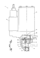
実施例1のスタータ1の構成を、図1を用いて説明する。
スタータ1は、車両(図示せず。)のエンジンルーム内に搭載されて内燃機関(図示せず。)を始動するものであり、電動モータ2、電磁スイッチ3、ピニオン4、シフトレバー5、ドライブシャフト6、ハウジング7および一方向クラッチ(図示せず。)等を備える。そして、スタータ1は、電磁スイッチ3によりシフトレバー5を回転させてピニオン4をリングギヤ8に噛み合わせるとともに、ピニオン4により電動モータ2のトルクを内燃機関のリングギヤ8に伝達して内燃機関を始動する。
[Configuration of Example 1]
The configuration of the starter 1 according to the first embodiment will be described with reference to FIG.
The starter 1 is mounted in an engine room of a vehicle (not shown) and starts an internal combustion engine (not shown), and includes an
ここで、電動モータ2は、内燃機関を始動するトルクを発生するものであり、電機子、界磁、ブラシおよび整流子等を有する周知の直流電動機である。
また、電磁スイッチ3は、乗員のスイッチオン操作により、ピニオン4を軸方向に前進させ、リングギヤ8に当接させて噛み合わせるとともに、電動モータ2への通電をオンするものであり、コイル、可動接点および固定接点等を有する周知構造を呈する。
Here, the
In addition, the
また、ピニオン4は、電動モータ2の出力軸と同軸に組み入れられたドライブシャフト6にヘリカルスプラインを介して嵌合している。すなわち、ピニオン4の内周、ドライブシャフト6の外周には、それぞれ、雌ヘリカルスプライン10、雄ヘリカルスプライン11が設けられており、雌、雄ヘリカルスプライン10、11が噛み合っている。
The
また、シフトレバー5は、支点部を中心として回転自在にハウジング7等により支持されている。そして、一端がピニオン4の側に保持され(後記するホルダ12に保持され、)、他端が電磁スイッチ3の側に連結されている。これにより、シフトレバー5は、電磁スイッチ3が動作することでピニオン4を軸方向に前進させ、電磁スイッチ3が動作を停止することで、ピニオン4を軸方向に後退させる。
The
また、ドライブシャフト6は、例えば、遊星歯車式の減速機(図示せず。)を介して電動モータ2からトルクを伝達されて回転駆動されるものであり、電動モータ2の出力軸と同軸に組み入れられている。
さらに、ハウジング7は、ピニオン4やドライブシャフト6等を収容してスタータ1の外郭の一部をなす。また、ハウジング7の先端には、ドライブシャフト6の先端を回転自在に支持する軸受13が収容されている。
The
Further, the
なお、一方向クラッチは、電動モータ2のトルクがドライブシャフト6、ピニオン4を介してリングギヤ8に伝わるのを許容し、内燃機関の始動後、空転して内燃機関のトルクがドライブシャフト6から電動モータ2の出力軸に伝わるのを遮断する周知構造を有するものである。
The one-way clutch allows the torque of the
以上の構成により、スタータ1では、乗員のスイッチオン操作により電磁スイッチ3が動作すると、シフトレバー5が回転駆動されてピニオン4およびホルダ12が一体になって軸方向に前進するとともに電動モータ2への通電がオンされ電動モータ2がトルクの出力を開始する。これにより、ピニオン4がリングギヤ8に当接して噛み合うとともに、電動モータ2のトルクによりリングギヤ8が回されて内燃機関が始動される。
With the above configuration, in the starter 1, when the
また、内燃機関の始動後、リングギヤ8が高速回転を開始するとピニオン4およびドライブシャフト6も高速回転して一方向クラッチが空転し、ドライブシャフト6と電動モータ2との間のトルクの伝達が遮断される。やがて、電磁スイッチ3が動作を停止すると、シフトレバー5がピニオン4の前進時とは逆の方向に回転駆動されてピニオン4が軸方向に後退し、ピニオン4がリングギヤ8から離脱する。また、電動モータ2への通電がオフされ電動モータ2がトルクの出力を停止する。
In addition, after the internal combustion engine is started, when the ring gear 8 starts to rotate at high speed, the
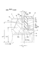
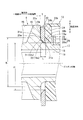
以下、スタータ1の特徴的な構成等を、図2を用いて説明する。
まず、ピニオン4は、歯先を有して実質的にリングギヤ8にかみ合う歯部15を具備し、歯部15は、冷鍛製造において軸方向一端側に型を抜くことで設けられている。また、歯部15の軸方向他端側に連続するフランジ状の部分は、歯部15の歯先を形成する冷鍛製造において打ち抜かれない部分であって歯底部16をなす。
Hereinafter, a characteristic configuration and the like of the starter 1 will be described with reference to FIG.
First, the
さらに、ピニオン4は、歯底部16から軸方向他端側に軸方向に伸びる円筒状の筒部17を有している。また、筒部17は段を形成して縮径しており、段の軸方向他端側は軸方向一端側よりも小径である(以下、筒部17において段の軸方向他端側、一端側の部分をそれぞれ小径部18、大径部19と呼ぶ。)。そして、筒部17は、冷鍛製造において軸方向他端側に型を抜くことで設けられている。このため、大径部19の外周面19aの内、歯底部16の軸方向他端側の端面16aから連続する軸方向の所定範囲は、端面16aに近いほど径大であり、かつ、内周側に凹をなすテーパ状の曲面20である。
Further, the
そして、曲面20は、曲面20以外の外周面19a、および、端面16aと滑らかに連続している。
なお、以下の説明では、曲面20の軸方向一端(つまり、端面16aと曲面20との接続部)を曲面一端20aと呼び、曲面20の軸方向他端(つまり、曲面20以外の外周面19aと曲面20との接続部)を曲面他端20bと呼ぶ。
The
In the following description, one end in the axial direction of the curved surface 20 (that is, the connecting portion between the
そして、スタータ1は、特徴的な構成要素として以下のホルダ12およびワッシャ22を備える。
まず、ホルダ12は、シフトレバー5の一端(図1参照。:以下、レバー端23と呼ぶことがある。)を保持する樹脂製の部材であり、筒部17の大径部19に嵌合されてピニオン4に一体化している。なお、ホルダ12は、ピニオン4に対し相対回転可能となるように嵌合されており、歯底部16の軸方向他端側に位置する。また、ホルダ12は、以下の一端側、他端側規制部24、25および回転規制部26を有し、一端側、他端側規制部24、25および回転規制部26により形成される領域にレバー端23を収容している。
The starter 1 includes the following
First, the
ここで、一端側、他端側規制部24、25は、レバー端23に軸方向一端側、他端側それぞれの側で接触してレバー端23の軸方向への移動を規制する部分であり、筒部17が通る嵌合穴は一端側規制部24に設けられている。また、回転規制部26は、ホルダ12自身の回転を規制するものであり、一端側、他端側規制部24、25を軸方向に架橋するように設けられ、レバー端23の外周側に配置されている。そして、ホルダ12全体が回転しようとすると回転規制部26がレバー端23に当たり、回転規制部26がレバー端23に当たることによってホルダ12全体の回転が規制される。
Here, the one end side and the other end
次に、ワッシャ22は、ピニオン4とホルダ12との間に配置され、ピニオン4とホルダ12とにより軸方向に挟まれて保持されている。
すなわち、ワッシャ22の軸方向一端側の金属面22aは歯底部16の端面16aに接触する。つまり、端面16aはワッシャ22に接触する接触面をなす(以下、端面16aを金属面16aと呼ぶ。)。また、ワッシャ22の軸方向他端側の金属面22bは一端側規制部24の軸方向一端面に接触している。つまり、一端側規制部24の軸方向一端面は、ホルダ12の表面の内、ワッシャ22に軸方向に接触する接触面をなす(以下、一端側規制部24の軸方向一端面を樹脂面24bと呼ぶ。)。
Next, the
That is, the
そして、ワッシャ22の内周には筒部17の大径部19が通っており、ワッシャ22は、大径部19に対して外周側に径方向の隙間27を形成して保持される。また、ワッシャ22の外周径は、金属面16aの外周径より大径であり、かつ、樹脂面24bの外周径よりも大径である。
The
さらに、ワッシャ22の内周は大径部19の外周よりも大径であり、ワッシャ22の内周径dは曲面一端20aの直径、すなわち、曲面20の最大径Dよりも大きい。ここで、実施例1では、曲面一端20aと曲面他端20bとの軸方向距離、すなわち、曲面20の軸方向長さLはワッシャ22の厚さtに等しい。そして、ワッシャ22は、ピニオン4と同軸に組み込まれており、ワッシャ22の内周面22cと曲面一端20aとの径方向の距離は全周で等しくd/2−D/2に一致している。また、内周面22cは、全範囲が曲面20から外周側に離れて隙間27を形成している。
Further, the inner periphery of the
なお、筒部17の小径部18には金属製の規制体28が圧入により装着されている。ここで、規制体28は、ホルダ12およびワッシャ22が筒部17から軸方向他端側に外れるのを規制するものである。また、規制体28は、小径部18に対して圧入される円筒部28aと、円筒部28aの軸方向一端に設けられる鍔部28bとを有する。そして、鍔部28bと一端側規制部24との間にもワッシャ29が配置され、ワッシャ29の内周面と小径部18の外周面との間に隙間が形成されている。
A
以上により、ホルダ12、ワッシャ22、規制体28およびワッシャ29はピニオン4とともに、シフトレバー5により駆動されるピニオン移動体を構成する。このため、スタータ1は、ピニオン移動体に金属製のピニオンチューブを含めず、かつ、ホルダ12を樹脂製にして軽量にするピニオンシフト構造となっている。
As described above, the
そして、電磁スイッチ3の動作により、シフトレバー5が回転駆動されると、レバー端23がホルダ12を軸方向一端側に押し、さらに、ホルダ12がワッシャ22を軸方向一端側に押すとともにワッシャ22がピニオン4を軸方向一端側に押すことで、ピニオン移動体が一体となって軸方向に前進する。これにより、ピニオン4がリングギヤ8に当接して噛み合うとともに、電動モータ2のトルクによりリングギヤ8が回されて内燃機関が始動される。
When the
また、内燃機関の始動後、電磁スイッチ3が動作を停止すると、シフトレバー5がピニオン移動体の前進時とは逆の方向に回転駆動される。これにより、レバー端23がホルダ12を軸方向他端側に押し、さらに、ホルダ12がワッシャ29を介して規制体28を軸方向他端側に押すことで、ピニオン移動体が一体となって軸方向に後退する。これにより、ピニオン4がリングギヤ8から離脱する。
When the
また、内燃機関の始動によりリングギヤ8が高速回転され、これに伴いピニオン4が高速で回転すると、金属面16aと金属面22aとの間、および、樹脂面24bと金属面22bとの間の両方またはいずれか一方で回転摺接が発生する。
すなわち、ピニオン4が回転すると、金属面16aがピニオン側摺接面となって金属面22aとの間で回転摺接したり、樹脂面24bがホルダ側摺接面となって金属面22bとの間で回転摺接したりする。
When the ring gear 8 is rotated at a high speed by the start of the internal combustion engine and the
That is, when the
また、ピニオン4が回転すると、規制体28が小径部18に対して圧入されていることから、鍔部28bとワッシャ29との間、および、一端側規制部24とワッシャ29との間の両方または一方で回転摺接が発生する。なお、ワッシャ29の内周面は小径部18の外周面との間に隙間を形成しているので、ワッシャ29の内周面と小径部18の外周面との間に回転摺接は発生しない。そして、ピニオン4、ワッシャ22およびホルダ12の3つの間の摩擦トルクの大きさは、規制体28の小径部18に対する圧入により設定される。
Further, when the
〔実施例1の効果〕
実施例1のスタータ1によれば、ホルダ12は、樹脂製であり、ピニオン4の軸方向他端側でピニオン4に相対回転可能に一体化され、シフトレバー5のレバー端23を保持してピニオン4とともに軸方向に移動する。また、ワッシャ22は、ピニオン4とホルダ12とにより軸方向に挟まれ、筒部17の外周面19aとの間に径方向の隙間27を形成して保持される。
このような構造により、ピニオンシフト構造を採用するスタータ1において、部品コストや加工コストを上げることなく、ホルダ12の回転摺接による磨耗を低減することができる。
[Effect of Example 1]
According to the starter 1 of the first embodiment, the
With such a structure, in the starter 1 adopting the pinion shift structure, it is possible to reduce wear due to the rotational sliding contact of the
すなわち、ワッシャ22は、安価であるにもかかわらず平面精度が高い。そこで、ワッシャ22をピニオン4とホルダ12とにより軸方向に挟むことで、ホルダ側摺接面である樹脂面24bに直接接触する接触面として、平面精度が高いワッシャ22の金属面22bを利用することができる。さらに、ピニオン側摺接面である金属面16aにも、平面精度が高いワッシャ22の金属面22aを直接接触させることができる。
That is, the
また、ワッシャ22がピニオン4およびホルダ12の両方に対して相対回転可能であることから、ピニオン4とワッシャ22との間に回転数差が生じ、さらに、ワッシャ22とホルダ12との間にも回転数差が生じる。このため、ワッシャ22とホルダ12との間の回転数差は、従来のピニオンシフト構造においてホルダ側摺接面とピニオン側摺接面との間に生じていた回転数差よりも小さくなる。この結果、ホルダ側摺接面である樹脂面24bが回転摺接により受ける摩擦トルクを低減することができる。
In addition, since the
以上により、ピニオンシフト構造を採用するスタータ1において、部品コストや加工コストを上げることなく、ホルダ12の回転摺接による磨耗を低減することができる。
例えば、ピニオン側摺接面(金属面16a)に関し、平面精度を高める加工を施さずに鍛造面のままピニオン4をスタータ1に組み込むことで、加工コストを上げることなく、ホルダ12の回転摺接による磨耗を低減することができる。
As described above, in the starter 1 that adopts the pinion shift structure, it is possible to reduce wear due to the rotational sliding contact of the
For example, with respect to the pinion side sliding contact surface (
また、ホルダ側摺接面(樹脂面24b)は、ワッシャ22の外周よりも小径であり、ピニオン4の外周はワッシャ22の外周よりも小径である。
これにより、ワッシャ22の外周を径大にしてワッシャ22の慣性モーメントを高めることで、ピニオン4の回転に伴うワッシャ22の連れ回りを抑制することができる。このため、樹脂面24bと金属面22bとの回転摺接が緩和される。この結果、ホルダ12の回転摺接による磨耗を更に低減することができる。
The holder side sliding contact surface (
Thereby, by enlarging the outer periphery of the
ここで、慣性モーメントは回転半径の2乗に比例して増加するので、ワッシャ22の外周の径大化によるワッシャ22の連れ回り抑制効果は、ホルダ12の磨耗低減効果を高める上で極めて有効である。
Here, since the moment of inertia increases in proportion to the square of the radius of rotation, the effect of suppressing the accompanying rotation of the
なお、慣性モーメントは質量を増やすことによっても高めることができるものの、ワッシャ22の質量を増やすとピニオン移動体の質量が増加して電磁スイッチ3に対する負荷が大きくなる。これに対し、ワッシャ22において外周を径大にすることで、質量の増加を抑えながら慣性モーメントを高めることができるので、電磁スイッチ3に対する負荷の増加を抑えつつ、ワッシャ22の慣性モーメントを高めてホルダ12の磨耗低減効果を高めることができる。
Although the moment of inertia can be increased by increasing the mass, increasing the mass of the
また、ワッシャ22の内周は筒部17の外周(曲面19)よりも大径である。
これにより、ワッシャ22の内周に筒部17の外周を接触させないようにすることができる。このため、ワッシャ22が筒部17から摩擦トルクを受けるのを阻止することができる。
Further, the inner periphery of the
Thereby, the outer periphery of the
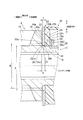
〔実施例2〕
実施例2のスタータ1によれば、図3に示すように、実施例1のスタータ1に対し、ワッシャ22の内周径dが大きく、内周面22cは更に曲面20から外周側に離れており、隙間27が拡大している。すなわち、実施例2のスタータ1では、ワッシャ22において内周径dを拡大することで、慣性モーメントの低下を抑えつつ質量を減らし、ピニオン移動体の質量を減少させて電磁スイッチ3の負荷を低減している。
[Example 2]
According to the starter 1 of the second embodiment, as shown in FIG. 3, the inner peripheral diameter d of the
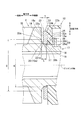
〔実施例3〕
実施例3のスタータ1によれば、図4に示すように、ワッシャ22の内周径dが曲面20の最大径Dよりも小さい。また、内周面22cの内、軸方向一端を含む角近傍の部分は、軸方向一端側ほど径大、かつ、内周側に凸をなす曲面31として設けられている。さらに、曲面31は、金属面22aと滑らかに連続している。
なお、以下の説明では、曲面31の軸方向一端(つまり、金属面22aと曲面31との接続部)を曲面一端31aと呼び、曲面31の軸方向他端を曲面他端31bと呼ぶ。
Example 3
According to the starter 1 of the third embodiment, the inner peripheral diameter d of the
In the following description, one end of the
そして、曲面一端31aは、ワッシャ22を組み付けた状態において、曲面一端20aに一致している。
また、実施例3のスタータ1によれば、ワッシャ22の外周径は、金属面16aの外周径より小径であり、かつ、樹脂面24bの外周径よりも小径である。
The
Moreover, according to the starter 1 of Example 3, the outer peripheral diameter of the
〔実施例4〕
実施例4のスタータ1によれば、図5に示すように、ワッシャ22の厚さtが曲面20の軸方向長さLよりも大きい。このため、隙間27は、実施例1に比べて軸方向他端側に拡大しており、内周面22cは、曲面20以外の外周面19aとの間にも隙間27を形成する。また、ワッシャ22の慣性モーメントは、厚さtを大きくして質量を増加させることで実施例1よりも高くなっている。
なお、ワッシャ22の内周径dは曲面20の最大径Dよりも大きい。また、ワッシャ22の外周径は、金属面16aの外周径より大径であり、かつ、樹脂面24bの外周径よりも大径である。
Example 4
According to the starter 1 of the fourth embodiment, the thickness t of the
The inner peripheral diameter d of the
〔実施例5〕
実施例5のスタータ1によれば、図6に示すように、ワッシャ22の厚さtが曲面20の軸方向長さLよりも小さい。このため、ピニオン4の軸よりも鉛直上方では、内周面22cの軸方向の一端(以下、内周一端22caと呼ぶ。)が曲面20に接触しており、ピニオン4の軸よりも鉛直下方では、内周面22cの全体が曲面20から離れている。
Example 5
According to the starter 1 of the fifth embodiment, the thickness t of the
また、金属面16aと金属面22aとの間に軸方向の隙間33が形成されている。
そして、電磁スイッチ3の動作により、シフトレバー5が回転駆動されると、レバー端23がホルダ12を軸方向一端側に押し、さらに、ホルダ12がワッシャ22を軸方向一端側に押す。
An
When the
これにより、隙間33が縮まり、ワッシャ22は、曲面20に乗り上げながら、動けなくなる位置まで軸方向に前進する。この間、ワッシャ22は、内周一端22caの曲面20への接触を通じてピニオン4を軸方向一端側に押す。その後、ピニオン4が回転すると、ピニオン4とワッシャ22との間の回転摺接は、内周一端22caと曲面20との間でのみ発生するので、ワッシャ22がピニオン4から受ける摩擦トルクは大幅に低減する。
As a result, the
なお、実施例5では、ワッシャ22の厚さtが曲面20の軸方向長さLよりも小さいので、ワッシャ22の質量が小さくなる。このため、ピニオン移動体の質量が小さくなるので、電磁スイッチ3を小型化する上で有利である。
In the fifth embodiment, since the thickness t of the
〔実施例6〕
実施例6のスタータ1によれば、図7に示すように、ワッシャ22の厚さtが曲面20の軸方向長さLよりも小さい。また、ワッシャ22の内周径dは曲面20の最大径Dよりも小さい。このため、金属面16aと金属面22aとの間に軸方向の隙間33が形成されている。
Example 6
According to the starter 1 of the sixth embodiment, the thickness t of the
また、実施例6のスタータ1によれば、実施例5のスタータ1と異なり、ピニオン4の軸の鉛直上方、下方ともに、内周一端22caが曲面20に接触している。これにより、電磁スイッチ3が動作しても、隙間33は詰まらず、ピニオン4は、内周一端22caと曲面20との接触により、ワッシャ22によって軸方向一端側に押され、軸方向に前進する。また、ピニオン4が回転すると、ピニオン4とワッシャ22との間の回転摺接は、内周一端22caと曲面20との間でのみ発生するので、ワッシャ22がピニオン4から受ける摩擦トルクは大幅に低減する。
Further, according to the starter 1 of the sixth embodiment, unlike the starter 1 of the fifth embodiment, the inner
〔実施例7〕
実施例7のスタータ1によれば、図8に示すように、ワッシャ22の厚さtが曲面20の軸方向長さLよりも小さい。また、ワッシャ22の内周面22cは、全体が曲面31であり円筒状の部分を有さず、金属面22aと滑らかに連続しており、曲面他端31bは金属面22bの内周縁に一致している。そして、ワッシャ22は、ピニオン4の軸よりも鉛直上方において、曲面他端31bにより曲面20以外の外周面19aに接触しており、ピニオン4の軸よりも鉛直下方では、内周面22c(曲面31)の全体が内周面19aから離れている。
Example 7
According to the starter 1 of the seventh embodiment, the thickness t of the
また、ワッシャ22の内周径dは曲面他端31bの直径であり、内周径dは曲面20の最大径Dよりも小さい。また、曲面一端31aの直径は最大径Dよりも大きく、曲面一端31aは、ピニオン4の軸よりも鉛直上方において、曲面一端20aよりも外周側に位置している。さらに、内周面22c(曲面31)の曲率半径は、鉛直方向に平行、かつ、ピニオン4の軸を含む断面において、曲面20の曲率半径よりも大きい。
Further, the inner peripheral diameter d of the
そして、電磁スイッチ3の動作によりシフトレバー5が回転駆動されると、ホルダ12がワッシャ22を軸方向一端側に押すことで、図9に示すように、隙間33が詰まって金属面22aが金属面16aに当たる。また、ワッシャ22は、金属面22aが金属面16aに当たるまでの間、曲面他端31bが曲面20に乗り上げながら軸方向に前進する。
なお、ホルダ12において、一端側規制部24に設けられた嵌合穴は、軸方向一端近傍が他の部分よりも僅かに拡大しており、樹脂面24aは、曲面他端22bよりも軸方向一端側に移動することができる。
When the
In addition, in the
そして、ピニオン4が回転すると、金属面16aは金属面22aに回転摺接し、内周面22は、曲面他端31bにおいてのみ曲面20の回転摺接を受ける。このため、ワッシャ22は、軸方向以外に径方向にピニオン4から摩擦トルクを受けるものの、径方向に受ける摩擦トルクは曲面他端31bにおいて受けるものに限定され、さほど大きくならない。
When the
また、実施例7のスタータ1によれば、内周面22cの全体を曲面31にするとともに内周面22c(曲面31)の曲率半径を曲面20の曲率半径よりも大きくし、さらに、曲面他端31bにおいてのみ内周面22cを外周面19aに接触させている。
これにより、曲面20への乗り上げが生じる場合に、曲面20に乗り上げる部分の磨耗を抑制することができる。このため、曲面20への乗り上げが生じる場合でも、シフトレバー5によるピニオン4の押出し量(軸方向への前進幅)の変動を抑制することができる。
Further, according to the starter 1 of the seventh embodiment, the entire inner
Thereby, when the climbing on the
なお、ワッシャ22の厚さtが小さくてもワッシャ22の曲面20への乗り上げを防止するべく、厚さtに合わせて曲面20の曲率半径低減を指向することも考えられる。しかし、切削により曲率半径を低減する場合、刃具が磨耗しやすく、加工速度を下げる必要がある。また、冷鍛製造の場合、曲率半径が小さいほど加工荷重を高める必要があり、型寿命が短くなってしまう。
このため、ワッシャ22の曲面20への乗り上げ防止を意図して曲面20の曲率半径を低減することは好ましくない。
In order to prevent the
For this reason, it is not preferable to reduce the radius of curvature of the
〔実施例8〕
実施例8のスタータ1によれば、図10に示すように、ピニオン4において金属面16aと外周面19aとの間が内周側にえぐり取られて窪み35が設けられ、曲面20が存在しない。また、ワッシャ22は内周面22cに曲面31が設けられておらず内周一端22caは、窪み35に突出している。さらに、ワッシャ22の内周径dは大径部19の外周径に等しく、ワッシャ22は、窪み35近傍の大径部19の外周面19aに接触して保持されている。このため、ピニオン4が回転すると、ワッシャ22は大径部19から径方向に摩擦トルクを受けるものの、径方向に受ける摩擦トルクは、窪み35近傍の大径部19の外周面19aにおいて受けるものに限定され、さほど大きくならない。
Example 8
According to the starter 1 of the eighth embodiment, as shown in FIG. 10, the
〔変形例〕
スタータ1の態様は、実施例に限定されず種々の変形例を考えることができる。
例えば、実施例のスタータ1によれば、ワッシャ22の枚数は1であったが、複数にしてもよい。
これにより、ワッシャ22の枚数を増減することで、ピニオン移動体の軸方向の寸法、質量を調節することができる。また、複数のワッシャ22の内、樹脂面24bに接触するワッシャ22の回転数を調節することができるので、ホルダ12の磨耗をより効果的に抑制することができる。
[Modification]
The mode of the starter 1 is not limited to the embodiment, and various modifications can be considered.
For example, according to the starter 1 of the embodiment, the number of
Thereby, the axial dimension and mass of the pinion moving body can be adjusted by increasing or decreasing the number of
また、内径や外径が異なる複数のリング状の円板を軸方向に重ねて接合することで1つのワッシャ22を設けてもよい。例えば、図11に示すように、外径が同じで内径が異なる2枚の円板22A、22Bを軸方向に重ねて接合することでワッシャ22を設けてもよい。
図11によれば、軸方向一端側の円板22Aの内周面22Acの直径は曲面20の最大径Dより大きく、大径部19の外周面19aとの間に隙間27が形成されている。また、円板22Bは筒部17に対し隙間嵌めされている。なお、円板22A、22Bの接合の態様は溶接やはんだ付け等である。また、円板22A、22Bを接合せず、それぞれ個別のワッシャ22として組み入れてもよい。
Further, one
According to FIG. 11, the diameter of the inner peripheral surface 22Ac of the
さらに、図12、図13に示すように、異なる2つの内径、外径を有する2つのリング状の円板22C、22Dを径方向に連結することで1つのワッシャ22を設けてもよい。この場合、金属面22aの範囲を径方向外周側、内周側それぞれの側に限定できるので、金属面22aが金属面16aから軸方向に受ける摩擦トルクを抑制することができる。
Furthermore, as shown in FIGS. 12 and 13, one
1 スタータ 2 電動モータ 3 電磁スイッチ 4 ピニオン 5 シフトレバー
8 リングギヤ 12 ホルダ 15 歯部 17筒部 19a 外周面 22 ワッシャ 23 レバー端(一端) 27 隙間
DESCRIPTION OF SYMBOLS 1
Claims (6)
前記ピニオン(4)は、前記リングギヤ(8)に噛み合う歯部(15)、および、この歯部(15)とは軸方向に関して前記リングギヤ(8)の反対側に伸びる筒部(17)を有するスタータ(1)において、
軸方向に関して前記リングギヤ(8)の反対側で前記ピニオン(4)に相対回転可能に一体化され、前記シフトレバー(5)の一端(23)を保持して前記ピニオン(4)とともに軸方向に移動する樹脂製のホルダ(12)と、
前記ピニオン(4)と前記ホルダ(12)とにより軸方向に挟まれ、前記筒部(17)の外周面(19a)との間に径方向の隙間(27)を形成して保持されるワッシャ(22)とを備えるスタータ(1)。 A pinion (4) for transmitting the torque of the electric motor (2) to the ring gear (8) of the internal combustion engine is provided, and the shift lever (5) is rotated by an electromagnetic switch (3) so that the pinion (4) is moved to the ring gear (8). )
The pinion (4) has a tooth portion (15) meshing with the ring gear (8), and a cylindrical portion (17) extending to the opposite side of the ring gear (8) with respect to the tooth portion (15) in the axial direction. In starter (1),
It is integrated with the pinion (4) so as to be relatively rotatable on the opposite side of the ring gear (8) with respect to the axial direction, and holds one end (23) of the shift lever (5) in the axial direction together with the pinion (4). A moving resin holder (12);
A washer sandwiched between the pinion (4) and the holder (12) in the axial direction and formed with a radial gap (27) between the outer peripheral surface (19a) of the cylindrical portion (17) and held. A starter (1) comprising (22).
前記ホルダ(12)の表面の内、前記ワッシャ(22)の一方の端面(22b)と軸方向に向かい合ったり接触したりする接触面(24b)は、前記ワッシャ(22)の外周よりも小径であることを特徴とするスタータ(1)。 The starter (1) according to claim 1,
Of the surface of the holder (12), a contact surface (24b) that faces or contacts one end surface (22b) of the washer (22) in the axial direction has a smaller diameter than the outer periphery of the washer (22). A starter (1) characterized by being.
前記ピニオン(4)の外周は、前記ワッシャ(22)の外周よりも小径であることを特徴とするスタータ(1)。 The starter (1) according to claim 1 or claim 2,
The starter (1), wherein an outer periphery of the pinion (4) is smaller in diameter than an outer periphery of the washer (22).
前記ワッシャ(22)の内周は、前記筒部(17)の外周よりも大径であることを特徴とするスタータ(1)。 The starter (1) according to any one of claims 1 to 3,
The starter (1), wherein an inner circumference of the washer (22) is larger than an outer circumference of the cylindrical portion (17).
前記ピニオン(4)は、軸方向に関して前記リングギヤ(8)の反対側で前記歯部(15)に連続する歯底部(16)を有し、
この歯底部(16)の前記リングギヤ(8)の反対側の端面が前記ワッシャ(22)の一方の端面(22a)と軸方向に向かい合ったり接触したりする接触面(16a)をなし、
前記筒部(17)は、前記歯底部(16)から軸方向に関して前記リングギヤ(8)の反対側に伸びており、
前記筒部(17)の外周面(19a)の内、前記接触面(16a)から連続する軸方向の所定範囲は、前記接触面(16a)に近いほど径大であり、かつ、内周側に凹をなすテーパ状の曲面(20)であり、
前記ワッシャ(22)の内周は、前記曲面(20)の一部に接触して保持されていることを特徴とするスタータ(1)。 A starter (1) according to any one of claims 1 to 4,
The pinion (4) has a tooth bottom portion (16) continuous with the tooth portion (15) on the opposite side of the ring gear (8) with respect to the axial direction,
An end surface of the tooth bottom portion (16) opposite to the ring gear (8) forms a contact surface (16a) that faces or contacts one end surface (22a) of the washer (22) in the axial direction,
The tube portion (17) extends from the tooth bottom portion (16) to the opposite side of the ring gear (8) in the axial direction,
Of the outer peripheral surface (19a) of the cylindrical portion (17), the predetermined range in the axial direction continuing from the contact surface (16a) is larger in diameter as being closer to the contact surface (16a), and the inner peripheral side. A tapered curved surface (20) having a recess
The starter (1), wherein an inner periphery of the washer (22) is held in contact with a part of the curved surface (20).
前記ワッシャ(22)の枚数は複数であることを特徴とするスタータ(1)。 Starter (1) according to any one of claims 1 to 5,
The starter (1), wherein the number of washers (22) is plural.
Priority Applications (4)
| Application Number | Priority Date | Filing Date | Title |
|---|---|---|---|
| JP2014010062A JP2015137602A (en) | 2014-01-23 | 2014-01-23 | starter |
| BR102015001342A BR102015001342A2 (en) | 2014-01-23 | 2015-01-21 | starter motor |
| US14/601,896 US20150204297A1 (en) | 2014-01-23 | 2015-01-21 | Starter |
| CN201510035526.8A CN104806413A (en) | 2014-01-23 | 2015-01-23 | Starter |
Applications Claiming Priority (1)
| Application Number | Priority Date | Filing Date | Title |
|---|---|---|---|
| JP2014010062A JP2015137602A (en) | 2014-01-23 | 2014-01-23 | starter |
Publications (1)
| Publication Number | Publication Date |
|---|---|
| JP2015137602A true JP2015137602A (en) | 2015-07-30 |
Family
ID=53544386
Family Applications (1)
| Application Number | Title | Priority Date | Filing Date |
|---|---|---|---|
| JP2014010062A Pending JP2015137602A (en) | 2014-01-23 | 2014-01-23 | starter |
Country Status (4)
| Country | Link |
|---|---|
| US (1) | US20150204297A1 (en) |
| JP (1) | JP2015137602A (en) |
| CN (1) | CN104806413A (en) |
| BR (1) | BR102015001342A2 (en) |
Citations (4)
| Publication number | Priority date | Publication date | Assignee | Title |
|---|---|---|---|---|
| JP2008115743A (en) * | 2006-11-02 | 2008-05-22 | Denso Corp | Starter |
| JP2009138678A (en) * | 2007-12-07 | 2009-06-25 | Denso Corp | Starter |
| JP2012193669A (en) * | 2011-03-16 | 2012-10-11 | Mitsubishi Electric Corp | Starter |
| JP2013083178A (en) * | 2011-10-07 | 2013-05-09 | Denso Corp | Starter |
Family Cites Families (8)
| Publication number | Priority date | Publication date | Assignee | Title |
|---|---|---|---|---|
| GB1547766A (en) * | 1975-08-21 | 1979-06-27 | Lucas Industries Ltd | Starter motors |
| JP3011091B2 (en) * | 1995-05-26 | 2000-02-21 | 株式会社デンソー | Starter |
| JP3767549B2 (en) * | 2002-12-10 | 2006-04-19 | 三菱電機株式会社 | Engine starter |
| CN101044314A (en) * | 2004-10-20 | 2007-09-26 | 株式会社美姿把 | Starter motor with idle gear |
| JP4375314B2 (en) * | 2005-09-26 | 2009-12-02 | 株式会社デンソー | Starter |
| FR2921124B1 (en) * | 2007-09-18 | 2014-11-21 | Valeo Equip Electr Moteur | OUTPUT SHAFT OF A STARTING DEVICE |
| FR2978500B1 (en) * | 2011-07-26 | 2015-03-13 | Valeo Equip Electr Moteur | LAUNCHER MOBILE ASSEMBLY - GEAR CONTROL LEVER WITH A STARTING CROWN OF A THERMAL MOTOR AND STARTER OF A THERMAL MOTOR COMPRISING SUCH AN ASSEMBLY |
| JP2013083177A (en) * | 2011-10-07 | 2013-05-09 | Denso Corp | Starter |
-
2014
- 2014-01-23 JP JP2014010062A patent/JP2015137602A/en active Pending
-
2015
- 2015-01-21 BR BR102015001342A patent/BR102015001342A2/en not_active IP Right Cessation
- 2015-01-21 US US14/601,896 patent/US20150204297A1/en not_active Abandoned
- 2015-01-23 CN CN201510035526.8A patent/CN104806413A/en active Pending
Patent Citations (4)
| Publication number | Priority date | Publication date | Assignee | Title |
|---|---|---|---|---|
| JP2008115743A (en) * | 2006-11-02 | 2008-05-22 | Denso Corp | Starter |
| JP2009138678A (en) * | 2007-12-07 | 2009-06-25 | Denso Corp | Starter |
| JP2012193669A (en) * | 2011-03-16 | 2012-10-11 | Mitsubishi Electric Corp | Starter |
| JP2013083178A (en) * | 2011-10-07 | 2013-05-09 | Denso Corp | Starter |
Also Published As
| Publication number | Publication date |
|---|---|
| BR102015001342A2 (en) | 2015-09-22 |
| CN104806413A (en) | 2015-07-29 |
| US20150204297A1 (en) | 2015-07-23 |
Similar Documents
| Publication | Publication Date | Title |
|---|---|---|
| JP4124091B2 (en) | Starter | |
| JP3843960B2 (en) | Starter | |
| JP4572912B2 (en) | Starter | |
| JP4552955B2 (en) | Starter | |
| JP5212076B2 (en) | Starter | |
| JP2015137602A (en) | starter | |
| EP1116901A2 (en) | Planetary gear reduction mechanism with tapered tooth end | |
| JP2009085408A (en) | Engine starting device | |
| JP2003074449A (en) | Starter | |
| JP4756361B2 (en) | Rotational force transmission device | |
| JP4745884B2 (en) | Mounting structure of bearing on rotating shaft and actuator of valve lift control device | |
| JP2007218217A (en) | Starter | |
| JP5874288B2 (en) | Starter | |
| JP2013083165A (en) | Starter | |
| CN106164467B (en) | Starter assembly for heat engine | |
| JP4305422B2 (en) | Starter and manufacturing method thereof | |
| JP5472367B2 (en) | Engine starter | |
| JP4157488B2 (en) | Engine starter | |
| JP4831045B2 (en) | Starter | |
| JP4227109B2 (en) | Starter motor with intermediate gear | |
| JP2010144827A (en) | Oil seal press fitting structure | |
| JP2006312891A (en) | Starter torque transmission device | |
| JP6637912B2 (en) | Chain saw | |
| US9528591B2 (en) | Vehicle transmission | |
| JPH07180642A (en) | Starter with epicyclic reduction mechanism and manufacture thereof |
Legal Events
| Date | Code | Title | Description |
|---|---|---|---|
| A621 | Written request for application examination |
Free format text: JAPANESE INTERMEDIATE CODE: A621 Effective date: 20160810 |
|
| A977 | Report on retrieval |
Free format text: JAPANESE INTERMEDIATE CODE: A971007 Effective date: 20170413 |
|
| A131 | Notification of reasons for refusal |
Free format text: JAPANESE INTERMEDIATE CODE: A131 Effective date: 20170418 |
|
| A521 | Written amendment |
Free format text: JAPANESE INTERMEDIATE CODE: A523 Effective date: 20170526 |
|
| A131 | Notification of reasons for refusal |
Free format text: JAPANESE INTERMEDIATE CODE: A131 Effective date: 20170704 |
|
| A02 | Decision of refusal |
Free format text: JAPANESE INTERMEDIATE CODE: A02 Effective date: 20171226 |