JP2014508574A - Detachable metal balloon delivery device and method - Google Patents
Detachable metal balloon delivery device and method Download PDFInfo
- Publication number
- JP2014508574A JP2014508574A JP2013549617A JP2013549617A JP2014508574A JP 2014508574 A JP2014508574 A JP 2014508574A JP 2013549617 A JP2013549617 A JP 2013549617A JP 2013549617 A JP2013549617 A JP 2013549617A JP 2014508574 A JP2014508574 A JP 2014508574A
- Authority
- JP
- Japan
- Prior art keywords
- balloon
- catheter
- medical device
- expanded
- aneurysm
- Prior art date
- Legal status (The legal status is an assumption and is not a legal conclusion. Google has not performed a legal analysis and makes no representation as to the accuracy of the status listed.)
- Granted
Links
- 229910052751 metal Inorganic materials 0.000 title claims abstract description 77
- 239000002184 metal Substances 0.000 title claims abstract description 77
- 238000000034 method Methods 0.000 title claims abstract description 69
- 206010002329 Aneurysm Diseases 0.000 claims abstract description 63
- 210000004204 blood vessel Anatomy 0.000 claims abstract description 36
- 229940079593 drug Drugs 0.000 claims abstract description 29
- 239000003814 drug Substances 0.000 claims abstract description 29
- 239000011800 void material Substances 0.000 claims abstract description 25
- 238000005868 electrolysis reaction Methods 0.000 claims abstract description 20
- BASFCYQUMIYNBI-UHFFFAOYSA-N platinum Chemical compound [Pt] BASFCYQUMIYNBI-UHFFFAOYSA-N 0.000 claims abstract description 16
- PCHJSUWPFVWCPO-UHFFFAOYSA-N gold Chemical compound [Au] PCHJSUWPFVWCPO-UHFFFAOYSA-N 0.000 claims abstract description 9
- 229910052737 gold Inorganic materials 0.000 claims abstract description 9
- 239000010931 gold Substances 0.000 claims abstract description 9
- BQCADISMDOOEFD-UHFFFAOYSA-N Silver Chemical compound [Ag] BQCADISMDOOEFD-UHFFFAOYSA-N 0.000 claims abstract description 8
- 229910052697 platinum Inorganic materials 0.000 claims abstract description 8
- 229910052709 silver Inorganic materials 0.000 claims abstract description 8
- 239000004332 silver Substances 0.000 claims abstract description 8
- 239000012530 fluid Substances 0.000 claims description 52
- 239000011148 porous material Substances 0.000 claims description 17
- 239000008194 pharmaceutical composition Substances 0.000 claims description 15
- 229910000679 solder Inorganic materials 0.000 claims description 13
- 239000000463 material Substances 0.000 claims description 11
- 230000002792 vascular Effects 0.000 claims description 10
- 239000007787 solid Substances 0.000 claims description 9
- 239000000725 suspension Substances 0.000 claims description 8
- 229910045601 alloy Inorganic materials 0.000 claims description 7
- 239000000956 alloy Substances 0.000 claims description 7
- 210000005166 vasculature Anatomy 0.000 claims description 7
- 229920000052 poly(p-xylylene) Polymers 0.000 claims description 6
- 230000006496 vascular abnormality Effects 0.000 claims description 6
- 108090000190 Thrombin Proteins 0.000 claims description 5
- 238000000576 coating method Methods 0.000 claims description 5
- -1 polyethylene Polymers 0.000 claims description 5
- 229920000642 polymer Polymers 0.000 claims description 5
- 229960004072 thrombin Drugs 0.000 claims description 5
- 239000000853 adhesive Substances 0.000 claims description 4
- 230000001070 adhesive effect Effects 0.000 claims description 4
- 239000011248 coating agent Substances 0.000 claims description 4
- 229920001971 elastomer Polymers 0.000 claims description 4
- FVEFRICMTUKAML-UHFFFAOYSA-M sodium tetradecyl sulfate Chemical compound [Na+].CCCCC(CC)CCC(CC(C)C)OS([O-])(=O)=O FVEFRICMTUKAML-UHFFFAOYSA-M 0.000 claims description 4
- 229940010746 sotradecol Drugs 0.000 claims description 4
- 102000010780 Platelet-Derived Growth Factor Human genes 0.000 claims description 3
- 108010038512 Platelet-Derived Growth Factor Proteins 0.000 claims description 3
- 239000011324 bead Substances 0.000 claims description 3
- 230000006835 compression Effects 0.000 claims description 3
- 238000007906 compression Methods 0.000 claims description 3
- 239000000835 fiber Substances 0.000 claims description 3
- 239000000155 melt Substances 0.000 claims description 3
- 239000004005 microsphere Substances 0.000 claims description 3
- 229910001000 nickel titanium Inorganic materials 0.000 claims description 3
- HLXZNVUGXRDIFK-UHFFFAOYSA-N nickel titanium Chemical compound [Ti].[Ti].[Ti].[Ti].[Ti].[Ti].[Ti].[Ti].[Ti].[Ti].[Ti].[Ni].[Ni].[Ni].[Ni].[Ni].[Ni].[Ni].[Ni].[Ni].[Ni].[Ni].[Ni].[Ni].[Ni] HLXZNVUGXRDIFK-UHFFFAOYSA-N 0.000 claims description 3
- 239000000806 elastomer Substances 0.000 claims description 2
- 229920002635 polyurethane Polymers 0.000 claims description 2
- 239000004814 polyurethane Substances 0.000 claims description 2
- 238000007493 shaping process Methods 0.000 claims description 2
- 239000000126 substance Substances 0.000 claims description 2
- 239000011810 insulating material Substances 0.000 claims 6
- 239000004677 Nylon Substances 0.000 claims 1
- 239000004698 Polyethylene Substances 0.000 claims 1
- 239000004743 Polypropylene Substances 0.000 claims 1
- 239000004809 Teflon Substances 0.000 claims 1
- 229920006362 Teflon® Polymers 0.000 claims 1
- 239000011805 ball Substances 0.000 claims 1
- 229920001778 nylon Polymers 0.000 claims 1
- 229920000573 polyethylene Polymers 0.000 claims 1
- 229920001155 polypropylene Polymers 0.000 claims 1
- 230000008467 tissue growth Effects 0.000 abstract description 6
- 206010053648 Vascular occlusion Diseases 0.000 abstract 1
- 238000007789 sealing Methods 0.000 abstract 1
- 208000021331 vascular occlusion disease Diseases 0.000 abstract 1
- 210000003739 neck Anatomy 0.000 description 12
- 239000007789 gas Substances 0.000 description 10
- 208000007536 Thrombosis Diseases 0.000 description 9
- 238000001802 infusion Methods 0.000 description 8
- 239000000243 solution Substances 0.000 description 8
- 238000003780 insertion Methods 0.000 description 6
- 230000037431 insertion Effects 0.000 description 6
- 238000000926 separation method Methods 0.000 description 6
- 238000002399 angioplasty Methods 0.000 description 5
- 230000009977 dual effect Effects 0.000 description 5
- 239000007788 liquid Substances 0.000 description 5
- PXHVJJICTQNCMI-UHFFFAOYSA-N Nickel Chemical compound [Ni] PXHVJJICTQNCMI-UHFFFAOYSA-N 0.000 description 4
- KDLHZDBZIXYQEI-UHFFFAOYSA-N Palladium Chemical compound [Pd] KDLHZDBZIXYQEI-UHFFFAOYSA-N 0.000 description 4
- 230000005856 abnormality Effects 0.000 description 4
- 238000004891 communication Methods 0.000 description 4
- 150000002739 metals Chemical class 0.000 description 4
- 239000008196 pharmacological composition Substances 0.000 description 4
- 239000004033 plastic Substances 0.000 description 4
- 229920003023 plastic Polymers 0.000 description 4
- FAPWRFPIFSIZLT-UHFFFAOYSA-M Sodium chloride Chemical compound [Na+].[Cl-] FAPWRFPIFSIZLT-UHFFFAOYSA-M 0.000 description 3
- 230000015572 biosynthetic process Effects 0.000 description 3
- 238000002788 crimping Methods 0.000 description 3
- 230000010339 dilation Effects 0.000 description 3
- 239000008177 pharmaceutical agent Substances 0.000 description 3
- 239000011343 solid material Substances 0.000 description 3
- 238000003466 welding Methods 0.000 description 3
- VYZAMTAEIAYCRO-UHFFFAOYSA-N Chromium Chemical compound [Cr] VYZAMTAEIAYCRO-UHFFFAOYSA-N 0.000 description 2
- 208000032843 Hemorrhage Diseases 0.000 description 2
- FYYHWMGAXLPEAU-UHFFFAOYSA-N Magnesium Chemical compound [Mg] FYYHWMGAXLPEAU-UHFFFAOYSA-N 0.000 description 2
- ZOKXTWBITQBERF-UHFFFAOYSA-N Molybdenum Chemical compound [Mo] ZOKXTWBITQBERF-UHFFFAOYSA-N 0.000 description 2
- XUIMIQQOPSSXEZ-UHFFFAOYSA-N Silicon Chemical compound [Si] XUIMIQQOPSSXEZ-UHFFFAOYSA-N 0.000 description 2
- RTAQQCXQSZGOHL-UHFFFAOYSA-N Titanium Chemical compound [Ti] RTAQQCXQSZGOHL-UHFFFAOYSA-N 0.000 description 2
- QCWXUUIWCKQGHC-UHFFFAOYSA-N Zirconium Chemical compound [Zr] QCWXUUIWCKQGHC-UHFFFAOYSA-N 0.000 description 2
- 238000004026 adhesive bonding Methods 0.000 description 2
- 229910052782 aluminium Inorganic materials 0.000 description 2
- XAGFODPZIPBFFR-UHFFFAOYSA-N aluminium Chemical compound [Al] XAGFODPZIPBFFR-UHFFFAOYSA-N 0.000 description 2
- 238000002583 angiography Methods 0.000 description 2
- 210000001367 artery Anatomy 0.000 description 2
- 208000034158 bleeding Diseases 0.000 description 2
- 230000000740 bleeding effect Effects 0.000 description 2
- 230000010261 cell growth Effects 0.000 description 2
- 229910052804 chromium Inorganic materials 0.000 description 2
- 239000011651 chromium Substances 0.000 description 2
- 229910017052 cobalt Inorganic materials 0.000 description 2
- 239000010941 cobalt Substances 0.000 description 2
- GUTLYIVDDKVIGB-UHFFFAOYSA-N cobalt atom Chemical compound [Co] GUTLYIVDDKVIGB-UHFFFAOYSA-N 0.000 description 2
- 239000002657 fibrous material Substances 0.000 description 2
- 230000012010 growth Effects 0.000 description 2
- 239000004816 latex Substances 0.000 description 2
- 229920000126 latex Polymers 0.000 description 2
- 229910052749 magnesium Inorganic materials 0.000 description 2
- 239000011777 magnesium Substances 0.000 description 2
- WPBNNNQJVZRUHP-UHFFFAOYSA-L manganese(2+);methyl n-[[2-(methoxycarbonylcarbamothioylamino)phenyl]carbamothioyl]carbamate;n-[2-(sulfidocarbothioylamino)ethyl]carbamodithioate Chemical compound [Mn+2].[S-]C(=S)NCCNC([S-])=S.COC(=O)NC(=S)NC1=CC=CC=C1NC(=S)NC(=O)OC WPBNNNQJVZRUHP-UHFFFAOYSA-L 0.000 description 2
- 238000005259 measurement Methods 0.000 description 2
- 239000000203 mixture Substances 0.000 description 2
- 229910052750 molybdenum Inorganic materials 0.000 description 2
- 239000011733 molybdenum Substances 0.000 description 2
- 229910052759 nickel Inorganic materials 0.000 description 2
- 229910052758 niobium Inorganic materials 0.000 description 2
- 239000010955 niobium Substances 0.000 description 2
- GUCVJGMIXFAOAE-UHFFFAOYSA-N niobium atom Chemical compound [Nb] GUCVJGMIXFAOAE-UHFFFAOYSA-N 0.000 description 2
- 229910052763 palladium Inorganic materials 0.000 description 2
- 229920001296 polysiloxane Polymers 0.000 description 2
- 239000005060 rubber Substances 0.000 description 2
- 229910052706 scandium Inorganic materials 0.000 description 2
- SIXSYDAISGFNSX-UHFFFAOYSA-N scandium atom Chemical compound [Sc] SIXSYDAISGFNSX-UHFFFAOYSA-N 0.000 description 2
- 229910052710 silicon Inorganic materials 0.000 description 2
- 239000010703 silicon Substances 0.000 description 2
- 239000011780 sodium chloride Substances 0.000 description 2
- 229910052715 tantalum Inorganic materials 0.000 description 2
- GUVRBAGPIYLISA-UHFFFAOYSA-N tantalum atom Chemical compound [Ta] GUVRBAGPIYLISA-UHFFFAOYSA-N 0.000 description 2
- 229910052719 titanium Inorganic materials 0.000 description 2
- 239000010936 titanium Substances 0.000 description 2
- 229910052720 vanadium Inorganic materials 0.000 description 2
- LEONUFNNVUYDNQ-UHFFFAOYSA-N vanadium atom Chemical compound [V] LEONUFNNVUYDNQ-UHFFFAOYSA-N 0.000 description 2
- XLYOFNOQVPJJNP-UHFFFAOYSA-N water Substances O XLYOFNOQVPJJNP-UHFFFAOYSA-N 0.000 description 2
- 230000037303 wrinkles Effects 0.000 description 2
- 229910052726 zirconium Inorganic materials 0.000 description 2
- 206010053567 Coagulopathies Diseases 0.000 description 1
- 229920001634 Copolyester Polymers 0.000 description 1
- 206010051425 Enterocutaneous fistula Diseases 0.000 description 1
- 108010010803 Gelatin Proteins 0.000 description 1
- 244000043261 Hevea brasiliensis Species 0.000 description 1
- 208000008081 Intestinal Fistula Diseases 0.000 description 1
- 208000031481 Pathologic Constriction Diseases 0.000 description 1
- 102000003978 Tissue Plasminogen Activator Human genes 0.000 description 1
- 108090000373 Tissue Plasminogen Activator Proteins 0.000 description 1
- 206010046996 Varicose vein Diseases 0.000 description 1
- 206010057469 Vascular stenosis Diseases 0.000 description 1
- 230000002159 abnormal effect Effects 0.000 description 1
- NIXOWILDQLNWCW-UHFFFAOYSA-N acrylic acid group Chemical group C(C=C)(=O)O NIXOWILDQLNWCW-UHFFFAOYSA-N 0.000 description 1
- 230000009471 action Effects 0.000 description 1
- 239000000560 biocompatible material Substances 0.000 description 1
- 239000008280 blood Substances 0.000 description 1
- 210000004369 blood Anatomy 0.000 description 1
- 210000004556 brain Anatomy 0.000 description 1
- 230000008859 change Effects 0.000 description 1
- 230000035602 clotting Effects 0.000 description 1
- 230000007547 defect Effects 0.000 description 1
- 238000012377 drug delivery Methods 0.000 description 1
- 230000000694 effects Effects 0.000 description 1
- 230000005611 electricity Effects 0.000 description 1
- 238000005323 electroforming Methods 0.000 description 1
- 238000009713 electroplating Methods 0.000 description 1
- 230000003898 enterocutaneous fistula Effects 0.000 description 1
- 230000006870 function Effects 0.000 description 1
- 229920000159 gelatin Polymers 0.000 description 1
- 239000008273 gelatin Substances 0.000 description 1
- 235000019322 gelatine Nutrition 0.000 description 1
- 235000011852 gelatine desserts Nutrition 0.000 description 1
- 239000003292 glue Substances 0.000 description 1
- 208000014617 hemorrhoid Diseases 0.000 description 1
- 206010020718 hyperplasia Diseases 0.000 description 1
- 238000001727 in vivo Methods 0.000 description 1
- 238000011065 in-situ storage Methods 0.000 description 1
- 238000010348 incorporation Methods 0.000 description 1
- 238000002347 injection Methods 0.000 description 1
- 239000007924 injection Substances 0.000 description 1
- 238000000608 laser ablation Methods 0.000 description 1
- 238000004021 metal welding Methods 0.000 description 1
- 229920003052 natural elastomer Polymers 0.000 description 1
- 229920001194 natural rubber Polymers 0.000 description 1
- 239000002245 particle Substances 0.000 description 1
- 230000037361 pathway Effects 0.000 description 1
- 229920000515 polycarbonate Polymers 0.000 description 1
- 239000004417 polycarbonate Substances 0.000 description 1
- 229920000728 polyester Polymers 0.000 description 1
- 229920002959 polymer blend Polymers 0.000 description 1
- 239000002861 polymer material Substances 0.000 description 1
- 229920000915 polyvinyl chloride Polymers 0.000 description 1
- 239000004800 polyvinyl chloride Substances 0.000 description 1
- 230000008569 process Effects 0.000 description 1
- 230000001737 promoting effect Effects 0.000 description 1
- 108090000623 proteins and genes Proteins 0.000 description 1
- 102000004169 proteins and genes Human genes 0.000 description 1
- 238000007634 remodeling Methods 0.000 description 1
- 229910001285 shape-memory alloy Inorganic materials 0.000 description 1
- 229920002379 silicone rubber Polymers 0.000 description 1
- 239000004945 silicone rubber Substances 0.000 description 1
- 238000005476 soldering Methods 0.000 description 1
- 239000010935 stainless steel Substances 0.000 description 1
- 229910001220 stainless steel Inorganic materials 0.000 description 1
- 230000036262 stenosis Effects 0.000 description 1
- 208000037804 stenosis Diseases 0.000 description 1
- 239000000758 substrate Substances 0.000 description 1
- 229920002725 thermoplastic elastomer Polymers 0.000 description 1
- 229960000187 tissue plasminogen activator Drugs 0.000 description 1
- 208000027185 varicose disease Diseases 0.000 description 1
- 210000003462 vein Anatomy 0.000 description 1
Images


Classifications
-
- A—HUMAN NECESSITIES
- A61—MEDICAL OR VETERINARY SCIENCE; HYGIENE
- A61B—DIAGNOSIS; SURGERY; IDENTIFICATION
- A61B17/00—Surgical instruments, devices or methods, e.g. tourniquets
- A61B17/12—Surgical instruments, devices or methods, e.g. tourniquets for ligaturing or otherwise compressing tubular parts of the body, e.g. blood vessels, umbilical cord
- A61B17/12022—Occluding by internal devices, e.g. balloons or releasable wires
- A61B17/12027—Type of occlusion
- A61B17/12031—Type of occlusion complete occlusion
-
- A—HUMAN NECESSITIES
- A61—MEDICAL OR VETERINARY SCIENCE; HYGIENE
- A61B—DIAGNOSIS; SURGERY; IDENTIFICATION
- A61B17/00—Surgical instruments, devices or methods, e.g. tourniquets
- A61B17/12—Surgical instruments, devices or methods, e.g. tourniquets for ligaturing or otherwise compressing tubular parts of the body, e.g. blood vessels, umbilical cord
- A61B17/12022—Occluding by internal devices, e.g. balloons or releasable wires
- A61B17/12099—Occluding by internal devices, e.g. balloons or releasable wires characterised by the location of the occluder
- A61B17/12109—Occluding by internal devices, e.g. balloons or releasable wires characterised by the location of the occluder in a blood vessel
- A61B17/12113—Occluding by internal devices, e.g. balloons or releasable wires characterised by the location of the occluder in a blood vessel within an aneurysm
-
- A—HUMAN NECESSITIES
- A61—MEDICAL OR VETERINARY SCIENCE; HYGIENE
- A61B—DIAGNOSIS; SURGERY; IDENTIFICATION
- A61B17/00—Surgical instruments, devices or methods, e.g. tourniquets
- A61B17/12—Surgical instruments, devices or methods, e.g. tourniquets for ligaturing or otherwise compressing tubular parts of the body, e.g. blood vessels, umbilical cord
- A61B17/12022—Occluding by internal devices, e.g. balloons or releasable wires
- A61B17/12131—Occluding by internal devices, e.g. balloons or releasable wires characterised by the type of occluding device
- A61B17/12136—Balloons
-
- A—HUMAN NECESSITIES
- A61—MEDICAL OR VETERINARY SCIENCE; HYGIENE
- A61B—DIAGNOSIS; SURGERY; IDENTIFICATION
- A61B17/00—Surgical instruments, devices or methods, e.g. tourniquets
- A61B17/12—Surgical instruments, devices or methods, e.g. tourniquets for ligaturing or otherwise compressing tubular parts of the body, e.g. blood vessels, umbilical cord
- A61B17/12022—Occluding by internal devices, e.g. balloons or releasable wires
- A61B17/12131—Occluding by internal devices, e.g. balloons or releasable wires characterised by the type of occluding device
- A61B17/12168—Occluding by internal devices, e.g. balloons or releasable wires characterised by the type of occluding device having a mesh structure
- A61B17/12172—Occluding by internal devices, e.g. balloons or releasable wires characterised by the type of occluding device having a mesh structure having a pre-set deployed three-dimensional shape
-
- A—HUMAN NECESSITIES
- A61—MEDICAL OR VETERINARY SCIENCE; HYGIENE
- A61F—FILTERS IMPLANTABLE INTO BLOOD VESSELS; PROSTHESES; DEVICES PROVIDING PATENCY TO, OR PREVENTING COLLAPSING OF, TUBULAR STRUCTURES OF THE BODY, e.g. STENTS; ORTHOPAEDIC, NURSING OR CONTRACEPTIVE DEVICES; FOMENTATION; TREATMENT OR PROTECTION OF EYES OR EARS; BANDAGES, DRESSINGS OR ABSORBENT PADS; FIRST-AID KITS
- A61F2/00—Filters implantable into blood vessels; Prostheses, i.e. artificial substitutes or replacements for parts of the body; Appliances for connecting them with the body; Devices providing patency to, or preventing collapsing of, tubular structures of the body, e.g. stents
- A61F2/02—Prostheses implantable into the body
- A61F2/04—Hollow or tubular parts of organs, e.g. bladders, tracheae, bronchi or bile ducts
- A61F2/06—Blood vessels
-
- A—HUMAN NECESSITIES
- A61—MEDICAL OR VETERINARY SCIENCE; HYGIENE
- A61F—FILTERS IMPLANTABLE INTO BLOOD VESSELS; PROSTHESES; DEVICES PROVIDING PATENCY TO, OR PREVENTING COLLAPSING OF, TUBULAR STRUCTURES OF THE BODY, e.g. STENTS; ORTHOPAEDIC, NURSING OR CONTRACEPTIVE DEVICES; FOMENTATION; TREATMENT OR PROTECTION OF EYES OR EARS; BANDAGES, DRESSINGS OR ABSORBENT PADS; FIRST-AID KITS
- A61F2/00—Filters implantable into blood vessels; Prostheses, i.e. artificial substitutes or replacements for parts of the body; Appliances for connecting them with the body; Devices providing patency to, or preventing collapsing of, tubular structures of the body, e.g. stents
- A61F2/95—Instruments specially adapted for placement or removal of stents or stent-grafts
- A61F2/958—Inflatable balloons for placing stents or stent-grafts
-
- A—HUMAN NECESSITIES
- A61—MEDICAL OR VETERINARY SCIENCE; HYGIENE
- A61M—DEVICES FOR INTRODUCING MEDIA INTO, OR ONTO, THE BODY; DEVICES FOR TRANSDUCING BODY MEDIA OR FOR TAKING MEDIA FROM THE BODY; DEVICES FOR PRODUCING OR ENDING SLEEP OR STUPOR
- A61M25/00—Catheters; Hollow probes
- A61M25/10—Balloon catheters
- A61M25/1027—Making of balloon catheters
- A61M25/1029—Production methods of the balloon members, e.g. blow-moulding, extruding, deposition or by wrapping a plurality of layers of balloon material around a mandril
-
- A—HUMAN NECESSITIES
- A61—MEDICAL OR VETERINARY SCIENCE; HYGIENE
- A61M—DEVICES FOR INTRODUCING MEDIA INTO, OR ONTO, THE BODY; DEVICES FOR TRANSDUCING BODY MEDIA OR FOR TAKING MEDIA FROM THE BODY; DEVICES FOR PRODUCING OR ENDING SLEEP OR STUPOR
- A61M31/00—Devices for introducing or retaining media, e.g. remedies, in cavities of the body
-
- A—HUMAN NECESSITIES
- A61—MEDICAL OR VETERINARY SCIENCE; HYGIENE
- A61B—DIAGNOSIS; SURGERY; IDENTIFICATION
- A61B17/00—Surgical instruments, devices or methods, e.g. tourniquets
- A61B17/12—Surgical instruments, devices or methods, e.g. tourniquets for ligaturing or otherwise compressing tubular parts of the body, e.g. blood vessels, umbilical cord
- A61B17/12022—Occluding by internal devices, e.g. balloons or releasable wires
- A61B17/12131—Occluding by internal devices, e.g. balloons or releasable wires characterised by the type of occluding device
- A61B17/1214—Coils or wires
-
- A—HUMAN NECESSITIES
- A61—MEDICAL OR VETERINARY SCIENCE; HYGIENE
- A61B—DIAGNOSIS; SURGERY; IDENTIFICATION
- A61B17/00—Surgical instruments, devices or methods, e.g. tourniquets
- A61B17/12—Surgical instruments, devices or methods, e.g. tourniquets for ligaturing or otherwise compressing tubular parts of the body, e.g. blood vessels, umbilical cord
- A61B17/12022—Occluding by internal devices, e.g. balloons or releasable wires
- A61B17/12131—Occluding by internal devices, e.g. balloons or releasable wires characterised by the type of occluding device
- A61B17/12168—Occluding by internal devices, e.g. balloons or releasable wires characterised by the type of occluding device having a mesh structure
- A61B17/12177—Occluding by internal devices, e.g. balloons or releasable wires characterised by the type of occluding device having a mesh structure comprising additional materials, e.g. thrombogenic, having filaments, having fibers or being coated
-
- A—HUMAN NECESSITIES
- A61—MEDICAL OR VETERINARY SCIENCE; HYGIENE
- A61B—DIAGNOSIS; SURGERY; IDENTIFICATION
- A61B17/00—Surgical instruments, devices or methods, e.g. tourniquets
- A61B17/12—Surgical instruments, devices or methods, e.g. tourniquets for ligaturing or otherwise compressing tubular parts of the body, e.g. blood vessels, umbilical cord
- A61B17/12022—Occluding by internal devices, e.g. balloons or releasable wires
- A61B17/12131—Occluding by internal devices, e.g. balloons or releasable wires characterised by the type of occluding device
- A61B17/12181—Occluding by internal devices, e.g. balloons or releasable wires characterised by the type of occluding device formed by fluidized, gelatinous or cellular remodelable materials, e.g. embolic liquids, foams or extracellular matrices
-
- A—HUMAN NECESSITIES
- A61—MEDICAL OR VETERINARY SCIENCE; HYGIENE
- A61B—DIAGNOSIS; SURGERY; IDENTIFICATION
- A61B17/00—Surgical instruments, devices or methods, e.g. tourniquets
- A61B2017/00004—(bio)absorbable, (bio)resorbable or resorptive
-
- A—HUMAN NECESSITIES
- A61—MEDICAL OR VETERINARY SCIENCE; HYGIENE
- A61B—DIAGNOSIS; SURGERY; IDENTIFICATION
- A61B17/00—Surgical instruments, devices or methods, e.g. tourniquets
- A61B2017/00526—Methods of manufacturing
-
- A—HUMAN NECESSITIES
- A61—MEDICAL OR VETERINARY SCIENCE; HYGIENE
- A61B—DIAGNOSIS; SURGERY; IDENTIFICATION
- A61B17/00—Surgical instruments, devices or methods, e.g. tourniquets
- A61B2017/00831—Material properties
- A61B2017/0084—Material properties low friction
- A61B2017/00849—Material properties low friction with respect to tissue, e.g. hollow organs
-
- A—HUMAN NECESSITIES
- A61—MEDICAL OR VETERINARY SCIENCE; HYGIENE
- A61B—DIAGNOSIS; SURGERY; IDENTIFICATION
- A61B17/00—Surgical instruments, devices or methods, e.g. tourniquets
- A61B2017/00831—Material properties
- A61B2017/00867—Material properties shape memory effect
-
- A—HUMAN NECESSITIES
- A61—MEDICAL OR VETERINARY SCIENCE; HYGIENE
- A61B—DIAGNOSIS; SURGERY; IDENTIFICATION
- A61B17/00—Surgical instruments, devices or methods, e.g. tourniquets
- A61B2017/00831—Material properties
- A61B2017/00884—Material properties enhancing wound closure
-
- A—HUMAN NECESSITIES
- A61—MEDICAL OR VETERINARY SCIENCE; HYGIENE
- A61B—DIAGNOSIS; SURGERY; IDENTIFICATION
- A61B17/00—Surgical instruments, devices or methods, e.g. tourniquets
- A61B2017/00831—Material properties
- A61B2017/00893—Material properties pharmaceutically effective
-
- A—HUMAN NECESSITIES
- A61—MEDICAL OR VETERINARY SCIENCE; HYGIENE
- A61B—DIAGNOSIS; SURGERY; IDENTIFICATION
- A61B17/00—Surgical instruments, devices or methods, e.g. tourniquets
- A61B17/12—Surgical instruments, devices or methods, e.g. tourniquets for ligaturing or otherwise compressing tubular parts of the body, e.g. blood vessels, umbilical cord
- A61B17/12022—Occluding by internal devices, e.g. balloons or releasable wires
- A61B2017/1205—Introduction devices
- A61B2017/12054—Details concerning the detachment of the occluding device from the introduction device
- A61B2017/12059—Joint of soluble material
-
- A—HUMAN NECESSITIES
- A61—MEDICAL OR VETERINARY SCIENCE; HYGIENE
- A61B—DIAGNOSIS; SURGERY; IDENTIFICATION
- A61B17/00—Surgical instruments, devices or methods, e.g. tourniquets
- A61B17/12—Surgical instruments, devices or methods, e.g. tourniquets for ligaturing or otherwise compressing tubular parts of the body, e.g. blood vessels, umbilical cord
- A61B17/12022—Occluding by internal devices, e.g. balloons or releasable wires
- A61B2017/1205—Introduction devices
- A61B2017/12054—Details concerning the detachment of the occluding device from the introduction device
- A61B2017/12063—Details concerning the detachment of the occluding device from the introduction device electrolytically detachable
-
- A—HUMAN NECESSITIES
- A61—MEDICAL OR VETERINARY SCIENCE; HYGIENE
- A61B—DIAGNOSIS; SURGERY; IDENTIFICATION
- A61B17/00—Surgical instruments, devices or methods, e.g. tourniquets
- A61B17/12—Surgical instruments, devices or methods, e.g. tourniquets for ligaturing or otherwise compressing tubular parts of the body, e.g. blood vessels, umbilical cord
- A61B17/12022—Occluding by internal devices, e.g. balloons or releasable wires
- A61B2017/1205—Introduction devices
- A61B2017/12054—Details concerning the detachment of the occluding device from the introduction device
- A61B2017/12068—Details concerning the detachment of the occluding device from the introduction device detachable by heat
- A61B2017/12077—Joint changing shape upon application of heat, e.g. bi-metal or reversible thermal memory
-
- A—HUMAN NECESSITIES
- A61—MEDICAL OR VETERINARY SCIENCE; HYGIENE
- A61B—DIAGNOSIS; SURGERY; IDENTIFICATION
- A61B17/00—Surgical instruments, devices or methods, e.g. tourniquets
- A61B17/22—Implements for squeezing-off ulcers or the like on the inside of inner organs of the body; Implements for scraping-out cavities of body organs, e.g. bones; Calculus removers; Calculus smashing apparatus; Apparatus for removing obstructions in blood vessels, not otherwise provided for
- A61B2017/22038—Implements for squeezing-off ulcers or the like on the inside of inner organs of the body; Implements for scraping-out cavities of body organs, e.g. bones; Calculus removers; Calculus smashing apparatus; Apparatus for removing obstructions in blood vessels, not otherwise provided for with a guide wire
-
- A—HUMAN NECESSITIES
- A61—MEDICAL OR VETERINARY SCIENCE; HYGIENE
- A61B—DIAGNOSIS; SURGERY; IDENTIFICATION
- A61B90/00—Instruments, implements or accessories specially adapted for surgery or diagnosis and not covered by any of the groups A61B1/00 - A61B50/00, e.g. for luxation treatment or for protecting wound edges
- A61B90/03—Automatic limiting or abutting means, e.g. for safety
- A61B2090/037—Automatic limiting or abutting means, e.g. for safety with a frangible part, e.g. by reduced diameter
-
- A—HUMAN NECESSITIES
- A61—MEDICAL OR VETERINARY SCIENCE; HYGIENE
- A61B—DIAGNOSIS; SURGERY; IDENTIFICATION
- A61B90/00—Instruments, implements or accessories specially adapted for surgery or diagnosis and not covered by any of the groups A61B1/00 - A61B50/00, e.g. for luxation treatment or for protecting wound edges
- A61B90/39—Markers, e.g. radio-opaque or breast lesions markers
- A61B2090/3966—Radiopaque markers visible in an X-ray image
-
- A—HUMAN NECESSITIES
- A61—MEDICAL OR VETERINARY SCIENCE; HYGIENE
- A61F—FILTERS IMPLANTABLE INTO BLOOD VESSELS; PROSTHESES; DEVICES PROVIDING PATENCY TO, OR PREVENTING COLLAPSING OF, TUBULAR STRUCTURES OF THE BODY, e.g. STENTS; ORTHOPAEDIC, NURSING OR CONTRACEPTIVE DEVICES; FOMENTATION; TREATMENT OR PROTECTION OF EYES OR EARS; BANDAGES, DRESSINGS OR ABSORBENT PADS; FIRST-AID KITS
- A61F2250/00—Special features of prostheses classified in groups A61F2/00 - A61F2/26 or A61F2/82 or A61F9/00 or A61F11/00 or subgroups thereof
- A61F2250/0058—Additional features; Implant or prostheses properties not otherwise provided for
- A61F2250/0096—Markers and sensors for detecting a position or changes of a position of an implant, e.g. RF sensors, ultrasound markers
- A61F2250/0098—Markers and sensors for detecting a position or changes of a position of an implant, e.g. RF sensors, ultrasound markers radio-opaque, e.g. radio-opaque markers
-
- A—HUMAN NECESSITIES
- A61—MEDICAL OR VETERINARY SCIENCE; HYGIENE
- A61M—DEVICES FOR INTRODUCING MEDIA INTO, OR ONTO, THE BODY; DEVICES FOR TRANSDUCING BODY MEDIA OR FOR TAKING MEDIA FROM THE BODY; DEVICES FOR PRODUCING OR ENDING SLEEP OR STUPOR
- A61M2210/00—Anatomical parts of the body
- A61M2210/12—Blood circulatory system
-
- Y—GENERAL TAGGING OF NEW TECHNOLOGICAL DEVELOPMENTS; GENERAL TAGGING OF CROSS-SECTIONAL TECHNOLOGIES SPANNING OVER SEVERAL SECTIONS OF THE IPC; TECHNICAL SUBJECTS COVERED BY FORMER USPC CROSS-REFERENCE ART COLLECTIONS [XRACs] AND DIGESTS
- Y10—TECHNICAL SUBJECTS COVERED BY FORMER USPC
- Y10T—TECHNICAL SUBJECTS COVERED BY FORMER US CLASSIFICATION
- Y10T29/00—Metal working
- Y10T29/49—Method of mechanical manufacture
- Y10T29/49826—Assembling or joining
Landscapes
- Health & Medical Sciences (AREA)
- Life Sciences & Earth Sciences (AREA)
- Engineering & Computer Science (AREA)
- Surgery (AREA)
- Heart & Thoracic Surgery (AREA)
- Biomedical Technology (AREA)
- Veterinary Medicine (AREA)
- Animal Behavior & Ethology (AREA)
- General Health & Medical Sciences (AREA)
- Public Health (AREA)
- Vascular Medicine (AREA)
- Nuclear Medicine, Radiotherapy & Molecular Imaging (AREA)
- Medical Informatics (AREA)
- Molecular Biology (AREA)
- Reproductive Health (AREA)
- Transplantation (AREA)
- Pulmonology (AREA)
- Cardiology (AREA)
- Oral & Maxillofacial Surgery (AREA)
- Hematology (AREA)
- Anesthesiology (AREA)
- Gastroenterology & Hepatology (AREA)
- Child & Adolescent Psychology (AREA)
- Biophysics (AREA)
- Manufacturing & Machinery (AREA)
- Neurosurgery (AREA)
- Surgical Instruments (AREA)
- Media Introduction/Drainage Providing Device (AREA)
- Materials For Medical Uses (AREA)
- Prostheses (AREA)
Abstract
カテーテルに取り付けられた、圧縮された膨張型の離脱式単一ローブ金属バルーンを備える医療用デバイス、および血管を閉塞するか、または血管動脈瘤を治療するための使用方法が開示される。このバルーンは、バルーンが膨張中に空隙空間の形状に一致するように、かつバルーンが外部力の印加によってその後成形され得るように、金、白金、または銀等の延性金属で作製することができる。このバルーンは、物理的手段または電解によって、カテーテルから離脱させることができるように構成することができる。バルーンの表面は、バルーンの壁内への組織成長を促進し、かつ薬物または薬理活性分子を放出するように構成することができ、それによって、血管閉塞または動脈瘤の封止が長期にわたり維持される。A medical device comprising a compressed, inflatable, detachable single lobe metal balloon attached to a catheter and methods of use for occluding a blood vessel or treating a vascular aneurysm are disclosed. The balloon can be made of a ductile metal such as gold, platinum, or silver so that the balloon conforms to the shape of the void space during inflation and can be subsequently shaped by application of an external force. . The balloon can be configured so that it can be detached from the catheter by physical means or by electrolysis. The surface of the balloon can be configured to promote tissue growth into the balloon wall and release drug or pharmacologically active molecules, thereby maintaining vascular occlusion or aneurysm sealing over time. The
Description
関連出願の相互参照
本出願は、「Detachable Metal Balloon Delivery Device and Method」と題する、2011年1月17日に出願された米国特許仮出願第61/433,305号の優先権を主張し、それは、参照によりその全体が本明細書に組み込まれる。
CROSS-REFERENCE TO RELATED APPLICATIONS This application, "Detachable Metal Balloon Delivery Device and Method" and entitled, claims the priority of US Provisional Patent Application No. 61 / 433,305, filed on January 17, 2011, it , Incorporated herein by reference in its entirety.
技術分野
本発明は、送達デバイスを利用して、体内の所望の位置に送達することができる、拡張型の離脱式金属バルーンの種々の形態に関する。本発明はさらに、バルーンをカテーテル送達デバイスに取り付ける方法、バルーンを圧縮する方法、圧縮されたバルーンを血管もしくは動脈瘤の選択されたセグメントの内腔内に位置付ける方法、バルーンを膨張させ、拡張させる方法、および、次いで、バルーンが拡張状態で定位置のままで、一方カテーテルが取り外されるように、バルーンをカテーテルから分離する方法に関する。さらに、本発明は、バルーンを所望の位置に位置付け、かつ膨張もしくは拡張させるためのカテーテルを含む、種々の送達デバイスに関する。
TECHNICAL FIELD The present invention relates to various forms of expandable detachable metal balloons that can be delivered to a desired location within the body using a delivery device. The present invention further includes a method for attaching a balloon to a catheter delivery device, a method for compressing a balloon, a method for positioning a compressed balloon within the lumen of a selected segment of a blood vessel or aneurysm, and a method for inflating and expanding a balloon. And then a method of separating the balloon from the catheter so that the balloon remains in place in the expanded state while the catheter is removed. Furthermore, the present invention relates to various delivery devices including a catheter for positioning and inflating or expanding a balloon in a desired position.
スウェーデンの血管造影における先駆者のSven−Ivar Seldingerは、血管内の前進中にカテーテルを支持する手段として、血管内への挿入のために可撓性ワイヤを適用した。その後、バルーンを含むカテーテルが開発され、血管を閉塞するために使用されている。ある特定の例において、これらのカテーテルのバルーン部分は、しばしば、血管を永久的に閉塞する目的で、カテーテル部分から分離または「離脱され」、カテーテル部分は取り外される一方、体内に残すことができる。従来の離脱式バルーンは、流体または気体を用いて伸張することによって膨張し、拡張することができる、シリコーン等の適合性非多孔性材料から形成され、カテーテルからのバルーンの離脱後に、バルーン圧力を維持するための弁を含む。 Sven-Ivar Seldinger, a pioneer in Swedish angiography, applied a flexible wire for insertion into a blood vessel as a means to support the catheter during advancement within the blood vessel. Later, catheters containing balloons were developed and used to occlude blood vessels. In certain instances, the balloon portions of these catheters are often separated or “detached” from the catheter portion for the purpose of permanently occluding the blood vessel, and the catheter portion can be removed while it remains in the body. Conventional detachable balloons are formed from a compatible non-porous material, such as silicone, that can be inflated and expanded by stretching with a fluid or gas, and after detaching the balloon from the catheter, the balloon pressure is reduced. Includes a valve to maintain.
時が経て、適合性離脱式シリコーンバルーンが、主な欠点を有したことが発見された。第1に、バルーンの平滑表面および材料特性は、閉塞された血管壁からの組織の組み込みを促進しなかった。したがって、離脱したバルーンは、遊動する傾向があり、血管系内の非標的位置に移動し、したがって、非標的血管の閉塞をもたらした。第2に、これらのバルーン上の弁は、しばしば、漏出し、適合性バルーンは、次いで、収縮され、バルーン移動のリスクを増大し、許容されない血管再開通率をもたらす。最後に、膨張されたとき、これらのバルーンは、弾性であり、膨張および離脱後の再形成に対して抵抗性がある。最後に、これらのバルーンの表面は、薬剤または他の薬理活性分子を送達するのに、特に好適ではない。 Over time, it was discovered that compatible detachable silicone balloons had major drawbacks. First, the smooth surface and material properties of the balloon did not promote tissue incorporation from the occluded vessel wall. Thus, the detached balloon tended to float and moved to a non-target location within the vasculature, thus resulting in occlusion of the non-target vessel. Second, the valves on these balloons often leak and the compatible balloon is then deflated, increasing the risk of balloon movement and leading to unacceptable vascular reopening rates. Finally, when inflated, these balloons are elastic and resistant to remodeling after inflation and withdrawal. Finally, the surfaces of these balloons are not particularly suitable for delivering drugs or other pharmacologically active molecules.
より近年では、コイル状金属ワイヤ(コイル)の短いセグメントは、血管および血管動脈瘤を閉塞するための医療用デバイスとして支持されてきた。コイルを用いて血管もしくは動脈瘤を治療するために、手術者は、カテーテルを血管系の内腔内に挿入し、カテーテル先端を所望の位置に操作する。定位置にあるカテーテル先端を用いて、手術者は、小さいコイルを、カテーテルを通して血管の内腔もしくは動脈瘤の空洞内に通過させる。多くのコイルが、しばしば、血管もしくは動脈瘤を完全に閉塞するために必要であり、高い費用および長期の治療時間をもたらす。また、コイルは、処置中に、不注意に治療位置から離れて移動し、非標的血管を閉塞し得、それによって、手術者は、やむを得ず非標的位置からコイルを回収する。 More recently, short segments of coiled metal wires (coils) have been supported as medical devices for occluding blood vessels and vascular aneurysms. To treat a blood vessel or aneurysm using a coil, the operator inserts the catheter into the lumen of the vasculature and manipulates the catheter tip to the desired position. With the catheter tip in place, the operator passes a small coil through the catheter and into the vessel lumen or aneurysm cavity. Many coils are often required to completely occlude a blood vessel or aneurysm, resulting in high costs and long treatment times. Also, during the procedure, the coil can inadvertently move away from the treatment location and occlude the non-target vessel, thereby unavoidably the surgeon retrieves the coil from the non-target location.
動脈瘤を治療するために金属バルーンを利用する、他の先行デバイスは、膨張、次いで、収縮が効果的であることを必要とする。例えば、Hinesによる米国特許公開第2007/0288083号は、バルーンの一方のローブ(lobe)が、動脈瘤内に挿入され、他方のローブが、親血管内のままであり、各ローブが、血管と動脈瘤との間の開口部の1つの側面を被覆する扁平なディスクを形成するように、両方のローブが、膨張され、次いで、収縮される、二重ローブ(bi−lobed)金属バルーンを説明する。この医療用デバイスは、いくつかの欠点を有する。例えば、空隙は、動脈瘤の内腔内のままであり、不完全な動脈瘤血栓症または再開通をもたらすことができる。加えて、崩壊したデバイスの一部分は、隣接する親血管の内腔内に突出し、ある程度の血管狭窄および不規則性をもたらし、治療された血管の血栓形成、内膜過形成、および狭窄のリスクを増大させる。 Other prior devices that utilize a metal balloon to treat an aneurysm require that inflation and then deflation be effective. For example, US Patent Publication No. 2007/0288083 by Hines states that one lobe of the balloon is inserted into the aneurysm and the other lobe remains in the parent vessel, each lobe being a vessel and Describes a bi-lobed metal balloon in which both lobes are inflated and then deflated to form a flat disk that covers one side of the opening between the aneurysm. To do. This medical device has several drawbacks. For example, the void may remain within the lumen of the aneurysm, resulting in incomplete aneurysm thrombosis or recanalization. In addition, a portion of the collapsed device protrudes into the lumen of the adjacent parent vessel, resulting in some degree of vascular stenosis and irregularity, reducing the risk of thrombus formation, intimal hyperplasia, and stenosis in the treated vessel. Increase.
したがって、空隙を充填するために膨張させ、弁の必要性なく、膨張されたまま送達デバイスから離脱させることができ、かつその後、所望の空隙に嵌合するように成形することができる、離脱式金属バルーンを有する医療用デバイスに対する必要性が存在する。その上、局所的薬物送達を提供するデバイスを有することが望ましい。 Thus, a detachable type that can be inflated to fill the gap, can be removed from the delivery device while inflated without the need for a valve, and can then be shaped to fit into the desired gap There is a need for medical devices having metal balloons. Moreover, it is desirable to have a device that provides local drug delivery.
本発明は、種々のデバイスを利用して所望の位置に送達することができ、かつ剛性もしくは半剛性の拡張された形態に拡張することができる材料からなる、バルーンに関する。本発明はさらに、圧縮されたバルーンを、血管もしくは動脈瘤の内腔内に定置する方法、バルーンを膨張させ、拡張する方法、および、次いで、バルーンを拡張もしくは膨張状態で定位置に残したまま、バルーンを送達デバイスから離脱させる方法に関する。さらに、本発明は、バルーンを所望の位置に位置付け、かつ膨張させ、拡張させるためのカテーテル等の種々の送達デバイスに関する。カテーテルおよび変性注入ワイヤは、かかる送達デバイスの例である。したがって、本発明は、例えば、拡張された金属バルーンを動脈瘤内に残すことによって、動脈瘤を治療するために使用することができる。さらに、金属バルーンの表面は、組織内成長を促進し、薬物、薬理活性分子、または薬理組成物を放出するように構成することができる。 The present invention relates to a balloon made of a material that can be delivered to a desired location utilizing a variety of devices and can be expanded into a rigid or semi-rigid expanded configuration. The present invention further provides a method of placing a compressed balloon within the lumen of a blood vessel or aneurysm, a method of inflating and expanding the balloon, and then leaving the balloon in place in an expanded or inflated state And a method of disengaging a balloon from a delivery device. The present invention further relates to various delivery devices such as catheters for positioning and inflating and expanding a balloon in a desired position. Catheters and modified infusion wires are examples of such delivery devices. Thus, the present invention can be used to treat an aneurysm, for example, by leaving an expanded metal balloon within the aneurysm. Furthermore, the surface of the metal balloon can be configured to promote tissue ingrowth and release a drug, pharmacologically active molecule, or pharmacological composition.
本発明は、血管もしくは動脈瘤、または他の血管異常を治療する際に使用するための、金属等の剛性もしくは半剛性材料を備えるバルーンに関する。一実施形態において、バルーンは、内部表面、外部表面、および約3μm〜60μmの範囲の厚さを有する壁を有する、単一ローブ(single−lobed)金属バルーンである。バルーンはまた、流体の通過を可能にする開口部を有する。バルーンの壁は、約0.1mm〜約20mmの範囲の直径を有する開口部を画定する。一実施形態において、バルーンは、壁の外部表面上に位置する外部層を有する。外部層は、多孔性構成を有し、例えば、スポンジ状金属、または、薬物、薬理活性分子、薬理組成物を含む流体もしくは固体材料を保持することができる、任意の他の多孔性材料から作製される。血栓症または組織増殖を促進する、任意の組成物を使用することができる。バルーンは、約2mm〜約100mmの範囲の拡張された直径、約0.004cc〜約100ccの範囲の拡張された容積、および約2mm〜約120mmの拡張された長さを有し得る。 The present invention relates to a balloon comprising a rigid or semi-rigid material, such as metal, for use in treating blood vessels or aneurysms, or other vascular abnormalities. In one embodiment, the balloon is a single-lobed metal balloon having an inner surface, an outer surface, and a wall having a thickness in the range of about 3 μm to 60 μm. The balloon also has an opening that allows the passage of fluid. The balloon wall defines an opening having a diameter in the range of about 0.1 mm to about 20 mm. In one embodiment, the balloon has an outer layer located on the outer surface of the wall. The outer layer has a porous configuration and is made of, for example, a spongy metal or any other porous material that can hold a fluid or solid material containing a drug, pharmacologically active molecule, pharmacological composition. Is done. Any composition that promotes thrombosis or tissue growth can be used. The balloon may have an expanded diameter in the range of about 2 mm to about 100 mm, an expanded volume in the range of about 0.004 cc to about 100 cc, and an expanded length of about 2 mm to about 120 mm.
バルーンは、任意に、開口したままであるか、または離脱時に封止することができる開口部を画定する、首部または茎部を有する。バルーンの壁は、金、白金、銀、チタン、バナジウム、アルミニウム、ニッケル、タンタル、ジルコニウム、クロム、シリコン、マグネシウム、ニオブ、スカンジウム、コバルト、パラジウム、マンガン、モリブデン、それらの合金、およびそれらの組み合わせからなる群から選択される金属から作製され得る。他の剛性材料、または材料の組み合わせは、それらが、圧縮状態から拡張状態に拡張することができ、通常の条件下で、それらの形状を維持しながら、体内で拡張されたままであるかぎり、使用することができる。外部層は、金、白金、銀、それらの合金、およびそれらの組み合わせからなる群から選択される、金属から作製され得る。 The balloon optionally has a neck or stem that defines an opening that can remain open or can be sealed upon withdrawal. Balloon walls are from gold, platinum, silver, titanium, vanadium, aluminum, nickel, tantalum, zirconium, chromium, silicon, magnesium, niobium, scandium, cobalt, palladium, manganese, molybdenum, alloys thereof, and combinations thereof It can be made from a metal selected from the group consisting of: Use other rigid materials, or combinations of materials, as long as they can expand from a compressed state to an expanded state and remain expanded in the body while maintaining their shape under normal conditions can do. The outer layer can be made from a metal selected from the group consisting of gold, platinum, silver, alloys thereof, and combinations thereof.
別の実施形態において、外部層は、約0.05μm〜約100μmの範囲の直径の複数の孔を有する。外部層はまた、トロンビン、エチオドール(Ethiodol)(登録商標)、ソトラデコル(Sotradecol)(登録商標)、血小板由来成長因子、およびそれらの組み合わせ等の血栓症を促進するもの、または、細胞および組織成長を促進するものを含む、薬物、薬理活性分子、または薬理組成物の懸濁液も含む。 In another embodiment, the outer layer has a plurality of pores with a diameter ranging from about 0.05 μm to about 100 μm. The outer layer also promotes thrombosis such as thrombin, Ethiodol®, Sotradecol, platelet-derived growth factor, and combinations thereof, or cell and tissue growth. Also included are suspensions of drugs, pharmacologically active molecules, or pharmacological compositions, including those that facilitate.
別の実施形態において、2つ以上の医療用デバイスのバルーンは、空隙を充填するために組み合わせて使用し得る。加えて、第2、第3、またはそれ以上のバルーンが、第1のバルーンによって充填されない残りの空隙を充填するために必要であり得る。これらのデバイスのバルーンは、典型的には、バルーン壁の外部表面上に外部層を有する。これらの金属バルーンの外部層は、バルーンの壁内への組織の成長を可能にする多孔性で作製することができるか、または薬物、薬理活性分子、または薬理組成物を放出するように構成することができる。 In another embodiment, the balloons of two or more medical devices may be used in combination to fill the void. In addition, a second, third, or more balloon may be needed to fill the remaining void that is not filled by the first balloon. The balloons of these devices typically have an outer layer on the outer surface of the balloon wall. The outer layer of these metal balloons can be made porous to allow tissue growth into the balloon wall or is configured to release a drug, pharmacologically active molecule, or pharmacological composition. be able to.
本発明はまた、離脱式金属バルーンを用いて、動脈瘤を治療する方法、血管を閉塞する方法、または他の血管異常を治療する方法にも関する。本方法は、送達デバイスを使用して、バルーンを所望の位置に位置付けるステップと、流体を用いて、バルーンを膨張させ、拡張させるステップと、バルーンを所望の位置で拡張状態に残したまま、送達デバイスをバルーンから離脱させるステップとを含む。一実施形態において、バルーンは、延性材料から作製される。 The invention also relates to a method of treating an aneurysm, occluding a blood vessel, or treating other vascular abnormalities using a removable metal balloon. The method includes using a delivery device to position the balloon in a desired location, using a fluid to inflate and expand the balloon, and delivering the balloon in an expanded state at the desired location. Detaching the device from the balloon. In one embodiment, the balloon is made from a ductile material.
別の実施形態において、本方法はまた、針を用いて血管にアクセスするステップと、針を介してガイドワイヤを挿入するステップと、針を取り外すステップと、任意に、血管シースを血管内に挿入するステップと、を含む。本方法はまた、ガイドワイヤを所望の位置に位置付けるステップと、カテーテル送達デバイスを挿入するステップと、カテーテル送達デバイスをガイドワイヤの上を前進させるステップと、それを所望の位置に位置付けるステップと、を含む。本方法はまた、バルーンを膨張させ、拡張させるステップと、バルーンをカテーテル送達デバイスから離脱させるステップと、カテーテル送達デバイスを取り外すステップと、ワイヤを取り外すステップと、シースを取り外すステップと、を含む。バルーンは、バルーン外部表面の少なくとも50%〜少なくとも90%が空隙の表面に接触するように、膨張される。バルーン外部表面は、任意に、約0.05μm〜約100μmの範囲の直径を有する孔を有する、多孔性外部層を含む。 In another embodiment, the method also includes accessing the blood vessel using a needle, inserting a guide wire through the needle, removing the needle, and optionally inserting a vascular sheath into the blood vessel. Including the steps of: The method also includes positioning the guidewire in a desired position, inserting the catheter delivery device, advancing the catheter delivery device over the guidewire, and positioning it in the desired position. Including. The method also includes inflating and expanding the balloon, detaching the balloon from the catheter delivery device, removing the catheter delivery device, removing the wire, and removing the sheath. The balloon is inflated so that at least 50% to at least 90% of the balloon outer surface contacts the surface of the void. The balloon outer surface optionally includes a porous outer layer having pores having a diameter in the range of about 0.05 μm to about 100 μm.
別の実施形態において、本方法はまた、針を用いて血管にアクセスするステップと、針を介してガイドワイヤを挿入するステップと、針を取り外すステップと、任意に血管シースを血管内に挿入するステップと、を含む。本方法はまた、カテーテルをガイドワイヤの上で前進させることによって、カテーテルを所望の位置に前進させるステップと、ガイドワイヤを取り外すステップと、カテーテルの内腔を通してワイヤ送達デバイスを挿入するステップと、それを所望の位置に位置付けるステップと、を含む。本方法はまた、バルーンを膨張させ、拡張させるステップと、バルーンをワイヤ送達デバイスから離脱させるステップと、ワイヤ送達デバイスを取り外すステップと、カテーテルを取り外すステップと、シースを取り外すステップと、を含む。バルーンは、バルーン外部表面の少なくとも50%〜少なくとも90%が空隙の表面と接触するように、膨張される。バルーン外部表面は、任意に、約0.05μm〜約10μmの範囲の直径の孔を有する多孔性外部層を含む。 In another embodiment, the method also includes accessing the blood vessel using a needle, inserting a guide wire through the needle, removing the needle, and optionally inserting a vascular sheath into the blood vessel. Steps. The method also includes advancing the catheter over a guide wire to advance the catheter to a desired position, removing the guide wire, inserting a wire delivery device through the lumen of the catheter, and Positioning at a desired position. The method also includes inflating and expanding the balloon, detaching the balloon from the wire delivery device, removing the wire delivery device, removing the catheter, and removing the sheath. The balloon is inflated so that at least 50% to at least 90% of the balloon outer surface is in contact with the void surface. The balloon outer surface optionally includes a porous outer layer having pores with a diameter ranging from about 0.05 μm to about 10 μm.
他の実施形態において、本方法はさらに、薬学的薬剤、または薬理活性分子の溶液もしくは懸濁液を、バルーン外部表面の外部層内に定置するステップと、拡張されたバルーンを所望の位置に位置付け、バルーンを定位置に残すことによって、薬学的薬剤もしくは薬理活性分子を所望の位置に送達するステップとを含み、分子の少なくともいくつかは、バルーンを出て囲繞する組織内に拡散する。本方法は、バルーンの開口部を送達デバイスに溶接すること、もしくははんだ付けすることと、バルーンをバルーンと送達デバイスとの間の溶接もしくははんだを溶解するための電解によって送達デバイスから離脱させることと、を含む。本方法はまた、バルーンを送達デバイスに糊付けすることと、膨張され、拡張されたバルーンを、機械的手段によって、またはバルーン自体の金属部分の電解によって、送達デバイスから離脱させることと、を含み得る。追加のステップは、送達デバイスからの離脱後に、拡張され、離脱したバルーンの開口部に外部力を印加して、バルーンを封止することと、を含み得る。 In other embodiments, the method further includes placing a solution or suspension of the pharmaceutical agent or pharmacologically active molecule in the outer layer of the outer surface of the balloon, and positioning the expanded balloon in the desired location. Delivering the pharmaceutical agent or pharmacologically active molecule to the desired location by leaving the balloon in place, wherein at least some of the molecules diffuse out of the balloon and into the surrounding tissue. The method includes welding or soldering a balloon opening to a delivery device and detaching the balloon from the delivery device by welding between the balloon and the delivery device or by electrolysis to dissolve the solder. ,including. The method may also include gluing the balloon to the delivery device and causing the inflated and expanded balloon to leave the delivery device by mechanical means or by electrolysis of a metal portion of the balloon itself. . An additional step may include applying an external force to the expanded and opened balloon opening to seal the balloon after removal from the delivery device.
本発明はまた、金属バルーンを位置付け、膨張させるための送達デバイスに関する。本デバイスは、上述のバルーンと同様の離脱式単一ローブ金属バルーンを含む。本デバイスはまた、流体源を有するか、そこに接続することができるカテーテルと、カテーテルを所望の位置に前進させるための誘導部材と、カテーテルをバルーンから離脱させるための離脱部材とを含む。カテーテルの代わりに、変性注入ワイヤを使用することができ、それによって、注入ワイヤが、ワイヤコアの周囲に巻き付けられたコイル部材からなる。実際には、位置付けられると、ワイヤコアは、取り外され、新たに作成された内腔を使用して、ワイヤハブからバルーンに流体を送達して、膨張による拡張をもたらす。 The present invention also relates to a delivery device for positioning and inflating a metal balloon. The device includes a detachable single lobe metal balloon similar to the balloon described above. The device also includes a catheter that has or can be connected to a fluid source, a guide member for advancing the catheter to a desired location, and a detachment member for detaching the catheter from the balloon. Instead of a catheter, a modified infusion wire can be used, whereby the infusion wire consists of a coil member wrapped around the wire core. In practice, once positioned, the wire core is removed and the newly created lumen is used to deliver fluid from the wire hub to the balloon, resulting in expansion by inflation.
したがって、誘導部材は、医療用デバイスを所望の位置に位置付けるための任意のデバイスもしくはシステムであってもよい。典型的には、誘導部材は、可撓性ガイドワイヤである。可撓性ガイドワイヤは、柔軟な丸みを帯びた先端もしくはJ形状の先端を有し得る。 Thus, the guide member may be any device or system for positioning the medical device in a desired position. Typically, the guide member is a flexible guide wire. The flexible guidewire can have a soft rounded tip or a J-shaped tip.
離脱部材は、バルーンをカテーテルから離脱させるための任意のデバイスもしくはシステムであってもよい。例示的な離脱部材は、細長い電解ワイヤである。電解ワイヤは、電流を運んで、カテーテルとバルーンとの間の溶接部もしくははんだを溶解し、それによって、カテーテルをバルーンから離脱または分離する、絶縁された伝導性ワイヤであり得る。あるいは、電解ワイヤは、電流を運んで、バルーン自体の金属部分を溶解し、それによって、カテーテルをバルーンから離脱または分離する、絶縁された伝導性ワイヤであり得る。別の実施形態において、バルーンの開口部は、送達デバイスに溶接され、バルーンは、溶接を溶解する電解によって送達デバイスから離脱される。あるいは、機械的離脱が、カテーテルがバルーンから物理的に分離される場合に生じてもよい。 The detachment member may be any device or system for detaching the balloon from the catheter. An exemplary release member is an elongated electrolytic wire. The electrolysis wire can be an insulated conductive wire that carries electrical current to melt the weld or solder between the catheter and the balloon, thereby detaching or separating the catheter from the balloon. Alternatively, the electrolysis wire can be an insulated conductive wire that carries electrical current to dissolve the metal portion of the balloon itself, thereby detaching or separating the catheter from the balloon. In another embodiment, the balloon opening is welded to the delivery device and the balloon is detached from the delivery device by electrolysis that dissolves the weld. Alternatively, mechanical detachment may occur when the catheter is physically separated from the balloon.
カテーテルは、1つ以上の内腔を画定する、1つ以上の中空の円筒状部材を含む。典型的には、カテーテルは、単一内腔カテーテル、または二重内腔カテーテルであり、第1の円筒状部材は、バルーンが定位置にあるとき、流体源からバルーンに流体を送達するように寸法決定され、第2の円筒状部材は、誘導部材の上を通過するように寸法決定される。単一円筒状部材が使用される場合、流体は、単一円筒状部材を介して流体源からバルーンに送達され、デバイスは、デバイスを誘導するように機能する別個のカテーテルの内腔を介して定位置に前進させられる。 The catheter includes one or more hollow cylindrical members that define one or more lumens. Typically, the catheter is a single lumen catheter or a dual lumen catheter, and the first cylindrical member is adapted to deliver fluid from a fluid source to the balloon when the balloon is in place. Dimensioned and the second cylindrical member is sized to pass over the guide member. When a single cylindrical member is used, fluid is delivered from the fluid source to the balloon via the single cylindrical member, and the device is routed through a separate catheter lumen that functions to guide the device. Advances to a fixed position.
バルーンは、カテーテルの外側に取り付けられ得る。一実施形態において、バルーンは、バルーンをカテーテルの外側に取り付ける前、または取り付けた後に、1つ以上の襞を形成するように折り畳まれ、襞は、不適合な血管形成バルーンの折り畳みと同様に、圧延され、圧縮される。種々の他の実施形態において、襞バルーンは、可撓性ガイドワイヤの端部上に嵌合し、別個のカテーテルの中空の円筒状部材内を移動するように折り畳まれ、圧縮される。折り畳まれ、圧縮されたバルーンは、カテーテルの内腔を通って移動し、所望の位置で出現する。所望の位置および誘導のために使用されるカテーテルの外側になると、バルーンは、膨張され、拡張され、送達デバイスから分離される。 The balloon can be attached to the outside of the catheter. In one embodiment, the balloon is folded to form one or more wrinkles before or after the balloon is attached to the outside of the catheter, and the wrinkles are rolled, similar to the folding of incompatible angioplasty balloons. And compressed. In various other embodiments, the hemorrhoid balloon fits over the end of the flexible guidewire and is folded and compressed to move within the hollow cylindrical member of a separate catheter. The folded and compressed balloon moves through the lumen of the catheter and emerges at the desired location. Once outside the catheter used for the desired location and guidance, the balloon is inflated, expanded and separated from the delivery device.
特定の実施形態において、カテーテルは、内腔を画定する、中空の円筒状部材を有する。円筒状部材は、流体源に取り付けられるか、または取り付けることができる、近位端を有する。円筒状部材は、ポリマーブレンドで作製され、約0.05mm〜約0.5mmの範囲の壁厚を有する。画定された内腔は、約0.15mm〜約2.2mmの範囲の直径を有する。カテーテルはまた、ガイドワイヤを受容するための第2の円筒状部材を含み得る。種々の他の実施形態において、離脱部材は、円筒状部材の外側表面上に位置し、流体源は、円筒状部材を介して、バルーンに気体、液体、またはそれらの組み合わせを送達する。他の実施形態において、バルーンは、挿入前にカテーテルに取り付けられる。取り付けは、金属溶接、糊付け、または圧着を介して行われ得る。 In certain embodiments, the catheter has a hollow cylindrical member that defines a lumen. The cylindrical member has a proximal end that is or can be attached to a fluid source. The cylindrical member is made of a polymer blend and has a wall thickness in the range of about 0.05 mm to about 0.5 mm. The defined lumen has a diameter in the range of about 0.15 mm to about 2.2 mm. The catheter may also include a second cylindrical member for receiving a guide wire. In various other embodiments, the detachment member is located on the outer surface of the cylindrical member, and the fluid source delivers gas, liquid, or a combination thereof to the balloon via the cylindrical member. In other embodiments, the balloon is attached to the catheter prior to insertion. Attachment can be done via metal welding, gluing, or crimping.
したがって、バルーンを送達して、動脈もしくは静脈等の生物学的導管、または動脈瘤等の生物学的導管異常を閉塞するために利用することができる、バルーンおよび送達デバイスが提供される、 Accordingly, balloons and delivery devices are provided that can be utilized to deliver balloons to occlude biological conduits such as arteries or veins, or biological conduit abnormalities such as aneurysms,
別の実施形態において、バルーンを膨張させ、拡張させるために使用される流体は、血栓形成を触媒する薬物または薬理活性分子を含むことができる。 In another embodiment, the fluid used to inflate and expand the balloon can include drugs or pharmacologically active molecules that catalyze thrombus formation.
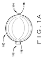
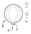
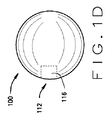
図1A〜Eに示される、本発明の離脱式金属バルーン100は、位置付けられると、膨張され、拡張され、かつ拡張された状態のまま、血管を閉塞し、動脈瘤を含む多くの血管状態もしくは異常を治療する、バルーンである。カテーテル300等の送達デバイスを使用して、バルーン100を所望の位置に送達する。図3〜6に示される、カテーテル、および取り付けられたバルーンを含む、医療用デバイス500は、血管を閉塞するか、または動脈瘤等の血管状態もしくは異常を治療するための方法の一部として使用することができる。
The
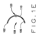
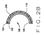
離脱式金属バルーン100は、図1Eに示されるように、単一の連続層もしくは壁102からなり得る。あるいは、バルーン100は、図2A〜Cに示されるように、単一の連続壁102、および1つ以上の多孔性層104を含む追加の層を含み得る。バルーン100は、流体を用いて膨張され、拡張されたとき、空間もしくは空隙108を画定する内部表面106を有する。バルーン100は、拡張されたとき、血管もしくは血管構造の内部壁と接触する、外部表面110を有する。流体は、質量分離なく、それらの相対位置を容易に移動し、変化する、粒子を有する物質である。バルーン100を膨張もしくは拡張させるために使用することができる流体には、液体、気体、およびそれらの組み合わせが挙げられる。
The
外部層104は、薬物、薬理活性分子、または薬学的組成物を含み得る多くの孔200を有することができる。有利に、バルーン100は、所望の位置に送達され、膨張され、拡張され、次いで、拡張状態でカテーテル300等の送達デバイスから離脱させることができる。拡張されたバルーン100は、典型的には、それが定置される空洞の形状と一致するが、隣接の拡張された血管形成バルーンによって印加される物理的力等の外部力を用いて成形することもできる。加えて、複数の離脱された金属バルーン100を利用して、所望の空隙を充填することができる。最後に、本発明は、具体的に、拡張状態で、血管もしくは動脈瘤の内腔もしくは空隙内に残る離脱式金属バルーンに関する。
The
金属バルーン100は、カテーテル300等の送達デバイスに取り付けられ、所望の位置に送達される。血管内腔を通してバルーン100を送達し、バルーンを膨張または拡張させ、そこから分離することができる、任意の送達デバイス部材は、一般に、許容される。本明細書に使用されるとき、バルーンの膨張または拡張は、流体、固体、またはそれらの組み合わせを使用する、バルーン100の部分的もしくは完全な膨張を指す。種々の実施形態において、バルーン100は、血管を閉塞するために完全に膨張させる必要がない。例えば、バルーン100は、流体を使用して部分的もしくは完全に膨張され得る。別の例において、バルーン100は、固体材料のみを使用して、または流体膨張と組み合わせて、部分的もしくは完全に拡張され得る。すべての実施形態において、バルーンは、送達デバイスからの離脱後に、拡張状態のままである。拡張状態は、最大バルーン容積の少なくとも10%、20%、または50%等のバルーン100の少なくとも部分的な膨張を指す。
カテーテルは、流体の注入もしくは抜脱を可能にするための管、血管、経路、または体腔内への挿入のための管状医療用デバイスである。血管の内腔内への挿入用に設計されたカテーテルは、典型的には、可撓性であり、しばしば、プラスチックもしくは金属からなる。ある特定の状況において、カテーテルは、カテーテルの管状部分によって画定される内腔を占領するワイヤもしくはトロカールを用いて、体内に定置される。定置されると、ワイヤもしくはトロカールは、流体の注入もしくは抜脱を可能にするために、取り外すことができる。 A catheter is a tubular medical device for insertion into a tube, blood vessel, pathway, or body cavity to allow fluid infusion or withdrawal. Catheters designed for insertion into the lumen of blood vessels are typically flexible and often consist of plastic or metal. In certain circumstances, the catheter is placed in the body using a wire or trocar that occupies the lumen defined by the tubular portion of the catheter. Once in place, the wire or trocar can be removed to allow fluid injection or withdrawal.
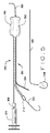
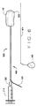
ワイヤは、通常、非常に可撓性の糸もしくは細長いロッドの形態の金属である。基本的な血管造影ガイドワイヤは、金属バネコイルによって被覆された、固定された固体金属コアからなる。注入ワイヤは、変性ガイドワイヤであり、組織プラスミノーゲン活性因子の溶液、血栓の崩壊を触媒するタンパク質等の流体の注入もしくは抜脱するために使用することができる内腔を残したまま、固体金属コアを取り外すことができる。このようにして、取り外し可能なコアワイヤを有する注入ワイヤは、カテーテルとして使用することができる。図11A〜Cは、金属バネコイルワイヤ1100および取り外し可能なコアワイヤ1102を有する注入ワイヤの種々の例を図示する。図11Cは、コアワイヤ1102が取り外された変性ガイドワイヤ1100の部分的断面を図示する。
The wire is usually a metal in the form of a very flexible thread or elongated rod. A basic angiographic guidewire consists of a fixed solid metal core covered by a metal spring coil. The infusion wire is a denatured guidewire that is a solid, leaving a lumen that can be used to inject or withdraw fluids such as tissue plasminogen activator solutions, proteins that catalyze the disruption of thrombus, etc. The metal core can be removed. In this way, an infusion wire having a removable core wire can be used as a catheter. FIGS. 11A-C illustrate various examples of infusion wires having a metal
好ましくは、送達デバイスは、図3A〜Cに示される、バルーン100を所望の部位に運ぶことができる、カテーテル300である。カテーテル300はまた、バルーンを膨張させ、拡張させるために使用される流体の通過も可能にしなければならない。カテーテル300は、内腔を画定する、少なくとも1つの中空の円筒状部材として画定され、カテーテルは、それが体内に挿入され、バルーン100を所望の位置に送達し、バルーンを膨張もしくは拡張させ、そこから分離することができるように設計され、寸法決定される。カテーテル300は、少なくとも1つの中空の円筒状部材、どちらかといえば、2つの中空の円筒状部材を含む可能性が高い。カテーテルが、2つの円筒状部材を含むとき、1つの円筒状部材は、ガイドワイヤ302等の誘導部材とともに動作して、デバイスを所望の位置に誘導することができる。離脱部材もまた、カテーテルとともに利用することができ、それによって、離脱部材は、円筒状部材のうちの1つの外側表面上に、もしくは壁内に運ばれるか、または円筒状部材のうちの1つの内腔を通過する。第2の円筒状部材は、流体を送達して、バルーン100を膨張もしくは拡張させ、バルーン100は、円筒状部材の外側壁上に位置することができる。代替物は、流体が円筒状部材を通過して、バルーンを膨張させ、拡張させる、単一の円筒状部材を含み、医療用デバイスは、それを膨張させ、拡張させ、離脱させることができる所望の位置に誘導する目的のために、別個のカテーテルを通して前進させられる。
Preferably, the delivery device is a
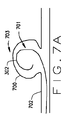
本発明の方法は、バルーン100を所望の位置に送達し、次いで、それを拡張状態に膨張させ、拡張させることを含む。拡張されると、送達デバイス(典型的には、カテーテル300)は、拡張されたままのバルーン100から分離される。離脱は、送達カテーテルの先端からバルーンをせん断するためにカテーテルを囲繞する別の円筒状部材を使用する等、機械的分離を介して、または電解方法によって、達成することができる。拡張されたバルーン100は、血管もしくは動脈瘤の内腔の少なくとも一部分を充填し、それによって、その後の血管もしくは動脈瘤からの出血のリスクを低減する。任意に、拡張されたバルーン100の外部層104は、薬物もしくは薬理活性分子を放出して、バルーン100の外部表面110上、および動脈瘤の空洞内の血栓形成を増大させる。任意に、多孔性外部層104は、金属表面内への隣接組織の成長を可能にする。方法の一部として、送達デバイスは、治療面積付近に定置されているガイドワイヤ302を使用して位置付けることができる。この実施形態において、送達デバイスは、定位置に、ガイドワイヤの上を前進させられ、次いで、ガイドワイヤ302は、取り外される。あるいは、方法の一部として、バルーン100は、ガイドカテーテル800を使用して位置付けることができ、図8A〜Eに示されるように、バルーンに取り付けられた送達デバイスは、ガイドカテーテルの内腔を通って動脈瘤の空洞内701に通過し、膨張もしくは拡張され、次いで、送達デバイスから分離される。
The method of the present invention includes delivering the
バルーン
図1A〜Eに説明され、例証されるように、バルーン100は、壁102によって、または1つ以上の首部116および118によって画定される、1つ以上の開口部112および114を有する。流体は、開口部112に進入し、内部表面106によって画定される、空間もしくは空隙108を拡張することができる。内部表面106および外部表面110は、バルーン壁厚120を画定する。バルーン100は、拡張され、送達デバイスからの分離後に拡張されたままになるように構成される。
Balloons As described and illustrated in FIGS. 1A-E, the
種々の実施形態において、首部116および118のうちの1つもしくは両方は、壁102から離れて突起することができるか、または内部空間もしくは空隙108内に突起する。首部116および118は、バルーンを送達デバイスに取り付けるために使用することができ、バルーン100を送達デバイスから分離する上での役割を果たし得る。
In various embodiments, one or both of the
離脱式バルーン100は、拡張後に種々の形状を取ることもできる金属から形成される。許容される形状には、円形、円筒形、または楕円形、ならびに動脈瘤の内腔空隙によって画定される形状が挙げられる。バルーン100が、一般に、管形状を有する一実施形態を使用して、血管の紡錘状動脈瘤拡大を治療することができる。この実施形態を使用して、血管もしくはそれらの分岐からの出血の治療を含む、種々の目的のために、正常な直径の血管を閉塞することもできる。
The
種々の実施形態において、バルーン100の寸法は、治療される状態によって選択される。1つの好ましい実施形態において、バルーン100の膨張した直径は、約2mm〜約100mmの範囲である。同様に、バルーンの好ましい膨張した容積は、約0.005cc〜約65ccの範囲である。一実施形態において、バルーン100は、好ましくは、約2mm〜約120mmの膨張した長さを有する。好ましくは、バルーン壁圧120は、約3μm〜60μmの範囲であり、開口部112は、約0.1mm〜約20mmの範囲の直径を有する。
In various embodiments, the dimensions of the
バルーン100は、1つ以上の生体適合性で、延性の金属から作製される。制限ではなく例として、金属は、金、白金、銀、チタン、バナジウム、アルミニウム、ニッケル、タンタル、ジルコニウム、クロム、シリコン、マグネシウム、ニオブ、スカンジウム、コバルト、パラジウム、マンガン、モリブデン、それらの合金、およびそれらの組み合わせからなる群から選択することができる。好ましい実施形態において、バルーン100の壁102は、連続的であり、バルーン100の外部層104は、金からなる多孔性金属から作製される。別の実施形態において、壁102および外部層104のうちの1つもしくは両方は、1つ以上の生体適合性で延性の金属から作製される。一実施形態において、壁102および/または外部層104は、電鋳または電気めっきによって形成される。他の実施形態において、壁102および/または外部層104は、ゴム、プラスチック、ポリマー、織りもしくは編み繊維材料、他の半剛性材料、またはそれらの組み合わせからなり得、バルーン100が、バルーンの内側および外側の圧力が同一もしくは同様である場合においても、拡張および離脱後に拡張状態のままであるように構成され得る。1つの特定の実施形態において、外部層は、パリレン(Parylene)(商標)からなる。
種々の実施形態において、図2Aおよび2Bに示されるように、壁102は、固体であり、外部層104は、多孔性である。外部層104の多孔性もしくはスポンジ性質は、孔200内に薬物、薬理活性分子、または薬学的組成物を含むように構成することができる。したがって、薬物、薬理活性分子、または薬学的組成物は、治療部位に送達することができる。薬物、薬理活性分子、または薬学的組成物は、バルーン100を所望の位置に位置付ける前に、外部層104の孔200内に組み込まれる。薬物、薬理活性分子、または薬学的組成物は、毛細管またはウィッキング作用を介して、孔200内に送達され得る。孔200は、約0.05μm〜約100μmの範囲の直径である。各バルーンのための孔の直径は、特定の薬物、薬理活性分子、または薬学的組成物を特定の速度で送達するように選択され得る。制限ではなく例として、バルーン100は、多孔性外部層104を有し得、孔の直径は、平均すると、約0.05μm〜約5μm、約5μm〜約25μm、または約25μm〜約100μmである。
In various embodiments, as shown in FIGS. 2A and 2B, the
薬物、薬理活性分子、または薬学的組成物は、外部層104の孔内に直接組み込まれ得るか、溶液および/または懸濁液として組み込まれ得る。制限ではなく例として、医薬品には、トロンビン、エチオドール(Ethiodol)(登録商標)、およびソトラデコル(Sotradecol)(登録商標)、またはそれらの組み合わせが挙げられる。血栓症および凝固を促進するか、またはバルーン100の多孔性外部壁への隣接組織の成長を刺激する、他の薬物、薬理活性分子、または薬学的組成物もまた、使用し得る。かかる薬物もしくは薬理活性分子は、バルーン100が、治療位置の組織に物理的に取り付けられるように、細胞もしくは組織成長を促進するための分子を含み得る。薬物または薬理活性分子が外部層104内に組み込まれる用量および方法は、実施される治療に拠って選択することができる。
The drug, pharmacologically active molecule, or pharmaceutical composition can be incorporated directly into the pores of the
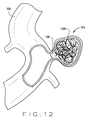
種々の実施形態において、壁102および外部層104は、異なる生体適合性金属からなる。他の実施形態において、壁102および外部層104は、同一の金属からなる。長期にわたり、バルーン100は拡張されたままであり、バルーンが最終的に、囲繞組織に付着するようになる。別の実施形態において、図12に示されるように、バルーン100は、金属性もしくはポリマー性コイル、金属性もしくはポリマー性拡張型構造、ビーズ、ボール、微小球、またはそれらの組み合わせ等の固体部材1200を用いて充填することができる。他の好適な生体適合性個体材料もまた、使用し得る。
In various embodiments, the
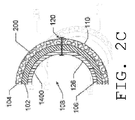
あるいは、バルーン100は、図2Cに示されるように、壁1400の内部表面上に追加のライナーもしくは層を備え得る。バルーン100の壁の内部表面上の追加のライナーもしくは層は、ポリマー、プラスチック、ラテックス、またはゴム、織りもしくは編み繊維材料、金属、他の材料、またはそれらの組み合わせからなり得る。好ましくは、内部層1400は、壁102の内部表面106に接着された、エラストマーコーティングである。内部層1400は、様々な厚さ、好ましくは、約0.5μm〜約59μmの範囲であってもよい。外部層、内部層、および壁の合計の厚さは、壁もしくは壁および2つの層が使用される場合にかかわらず、約3μm〜約60μmである。好ましい実施形態において、内部層1400は、パリレン(Parylene)(商標)であるが、ラテクッス、または他のエラストマーを使用し得る。内部層1400は、壁102に機械的特性(強度等)を追加する。さらに、内部層1400は、任意に、壁の金属部分が欠陥を含む場合に、バルーン100からの流体の漏れを防止する封止を形成することができる。バルーン壁102および任意の追加の層は、流体、液体、気体、または固体を用いてバルーンが拡張されるとき、内部空間もしくは空隙108が画定されるように、内部表面106もしくは126を画定する。
Alternatively, the
別の実施形態において、バルーン首部116もしくはバルーンの外部および/または内部は、パリレン(Parylene)(商標)等のポリマー等の絶縁基板を用いてコーティングされ得、バルーンもしくはバルーン首部の一部は、コーティングされていないままである。コーティングされていない部分は、コーティングプロセス中に意図的にコーティングされずに残され得るか、または、レーザーアブレーションもしくは他の好適なプロセスによってコーティング後に暴露され得る。拡張後、バルーンもしくはバルーン首部のコーティングされていない部分は、電気を伝導するための電解ワイヤ320もしくは他の絶縁された伝導性ワイヤを用いて電気的に連結され得、電流は、電源からバルーンもしくはバルーン首部のコーティングされていない部分まで通過して、電解を実施し、コーティングされていない部分の少なくとも一部分を溶解し、それによって、拡張されたバルーン100を送達カテーテルから分離することができる。
In another embodiment, the
送達デバイス
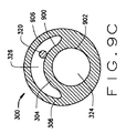
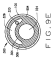
送達デバイスは、図4A〜Cに示されるように単一の内腔、または図3A〜Cに示されるように多内腔カテーテルであり得る。例えば、1つの潜在的なカテーテル300は、二重内腔カテーテルを形成するように、内腔を画定する2つの中空の円筒状部材もしくは管を備える。1つの内腔は、ガイドワイヤ302等の誘導部材の通路用であり、第2の内腔は、バルーン100を膨張させ、拡張させるための、バルーンへの流体もしくは気体の通過用である。一般に、金属バルーンに円形形状を用いる、この実施形態は、血管の限局性、偏心性、円形、および嚢状動脈瘤拡大または動脈瘤を治療するために使用することができる。カテーテル300は、圧縮形態のバルーン100等を用いて、血管系を通過するように構成することができる。カテーテル300は、バルーンからカテーテルを分離し、それによって、拡張されたバルーン100を定位置にしたまま、カテーテルが身体から取り外されることを可能にするための、図3Cに示される電解ワイヤ320等の離脱部材を含む。
Delivery Device The delivery device can be a single lumen as shown in FIGS. 4A-C or a multi-lumen catheter as shown in FIGS. For example, one
一実施形態において、中空の円筒状部材は、約0.05mm〜約0.5mmの範囲の壁厚を有する。好ましくは、円筒状壁厚は、約0.05mm〜約0.15mmの範囲である。円筒状部材によって画定された内腔は、約0.15mm〜約2.2mmの範囲の直径を有する。好ましい実施形態において、内腔の直径は、約0.7mm〜約1.57mmの範囲である。一実施形態において、カテーテル300は、収縮形状、圧縮形状、および/または襞形状でカテーテルの外部表面に取り付けられたバルーン100とともに構成される。カテーテル300は、圧縮されたバルーン100が所望の位置になるまで、ガイドワイヤ302の上を前進させ、そこで、バルーンは、拡張され、カテーテルから分離される。別の実施形態において、バルーン100は、収縮形状、圧縮形状、および/または襞形状でカテーテル300に取り付けられる。カテーテル300は、圧縮されたバルーン100が所望の位置になるまで、より大きい誘導カテーテルの内腔を完全に通過するように構成され、そこで、バルーンは、拡張され、カテーテルから分離される。
In one embodiment, the hollow cylindrical member has a wall thickness in the range of about 0.05 mm to about 0.5 mm. Preferably, the cylindrical wall thickness ranges from about 0.05 mm to about 0.15 mm. The lumen defined by the cylindrical member has a diameter in the range of about 0.15 mm to about 2.2 mm. In a preferred embodiment, the lumen diameter ranges from about 0.7 mm to about 1.57 mm. In one embodiment, the
カテーテル300は、生体適合性材料からなる。制限ではなく例として、カテーテル300およびその種々の構成要素は、シリコーンゴム、天然ゴム、ポリ塩化ビニル、ポリウレタン、コポリエステルポリマー、熱可塑性ゴム、シリコーン−ポリカーボネートコポリマー、ポリエチレンエチル−ビニル−アセテートコポリマー、織りポリエステル繊維、またはそれらの組み合わせからなり得る。一実施形態において、中空の円筒状部材の壁は、使用中にカテーテル300の制御を強化し、そのねじれを低減するために、編組ステンレス鋼またはニチノール等の金属を用いて強化され得る。
The
制限ではなく例として、誘導部材は、図3、5、および7に図示されるように、別個の可撓性ガイドワイヤ302であり得る。ガイドワイヤ302は、好ましくは、ガイドワイヤの遠位端を用いて、所望の位置に到達するのに十分な長さの、直線で柔軟な先端の血管造影ワイヤであり、近位端は、血管系内への進入地点から外側に、かつそこから離れて延在する。一実施形態において、ガイドワイヤ302は、典型的には、任意の印加された圧力が除去された後に、先端をJ形状に戻す、記憶合金または編組金属から構成される、湾曲したJ形状の遠位先端を有する。
By way of example and not limitation, the guide member can be a separate
図3Aは、離脱式金属バルーン医療用デバイスのカテーテル部分の一実施形態の長手方向図を図示する。図3B〜Cは、離脱式金属バルーン医療用デバイス500の一実施形態の長手方向図を図示する。カテーテル300は、ガイドワイヤ302の上を移動して、バルーン100を送達し、流体を送達して、バルーンを膨張させ、拡張させ、次いで、そこから分離される。カテーテル400は、1つの内腔を画定する(図4、6、および8に見られるような)、単一の中空の円筒状部材もしくは管を含むことができるか、またはカテーテル300は、多くの内腔を画定する(図3、5、および7に見られるような)、複数の中空の円筒状部材を含むことができる。示されるように、カテーテル300の一実施形態に好適な構成は、互いに隣接し、平行する、第1の中空の円筒状部材304および中空の円筒状部材306を含む。中空の円筒状部材304および306は、2つの内腔を画定する。1つの内腔326、流体もしくは気体送達内腔は、流体もしくは気体を提供して、バルーンを膨張させ、拡張させる。他の内腔324、誘導部材内腔は、バルーン100を定位置に位置付けるのを補助するために使用されるガイドワイヤ302を許容する。一実施形態において、中空の円筒状部材304および306は、第3の中空の円筒状部材(図示せず)内に収容され得る。他の実施形態において、第1の中空の円筒状部材304は、第2の中空の円筒状部材306内に位置し得るか、または中空の円筒状部材は、同軸であり得る。
FIG. 3A illustrates a longitudinal view of one embodiment of the catheter portion of a detachable metal balloon medical device. 3B-C illustrate a longitudinal view of one embodiment of a detachable metal balloon
第1の中空の円筒状部材306の近位端は、バルーン膨張もしくは拡張ポート308を含む。バルーン膨張もしくは拡張ポート308は、中空の円筒状部材306が、例えば、水、生理食塩水、または放射線不透過性溶液を含有するシリンジ314もしくはポンプ(図示せず)等の加圧流体もしくは気体源と通信することを可能にする。
The proximal end of the first hollow
加圧流体源によって提供される潜在的な流体には、液体、気体、またはそれらの組み合わせが挙げられる。制限ではなく例として、流体は、水、生理食塩溶液、放射線不透過性対照溶液、またはこれら3つの混合物もしくはいずれかであり得る。一実施形態において、流体は、バルーン膨張部位において、組織成長および/または血栓症を誘発するために、薬物もしくは薬理的活性分子の溶液もしくは懸濁液をさらに含み得る。別の実施形態において、流体は、バルーン100の膨張もしくは拡張、および拡張された形状の維持に役立つ、ワイヤ、コイル、支持構造、またはアクリルゼラチン微小球等の多くの固体を懸濁する。
Potential fluids provided by the pressurized fluid source include liquids, gases, or combinations thereof. By way of example and not limitation, the fluid can be water, saline solution, radiopaque control solution, or a mixture of any of these three. In one embodiment, the fluid may further comprise a solution or suspension of the drug or pharmacologically active molecule to induce tissue growth and / or thrombosis at the balloon inflation site. In another embodiment, the fluid suspends many solids, such as wires, coils, support structures, or acrylic gelatin microspheres, that help inflate or expand
中空の円筒状部材304の近位端は、ガイドワイヤポート310を含む。ガイドワイヤポート310は、中空の円筒状部材304内へのガイドワイヤ302の挿入を促進する。ガイドワイヤ302は、中空の円筒状部材304を介して供給され、カテーテル300の遠位端から外に延在する。この実施形態において、カテーテル300は、ガイドワイヤ302の上を前進し、血管の選択されたセグメント内、または血管動脈瘤の内腔内に位置付けられる。カテーテル300が所望の位置にあると、取り外し可能なワイヤ404は、送達デバイスから抜脱され、バルーン100は、バルーン膨張ポート308に接続されたシリンジ314によって中空の円筒状部材306に提供された流体によって、膨張もしくは拡張される。ガイドワイヤ302が取り外されると、ガイドワイヤポート310および中空の円筒状部材304は、生理食塩水、放射性不透過性対照剤、またはトロンビン等の薬物溶液等の流体を注入するために使用することができるか、または、流体もしくは血液を吸引するために使用することができる。
The proximal end of the hollow
カテーテル300の直径は、それが使用される特定の血管もしくは空洞の寸法に依って設計を選択することができる。例えば、医療用デバイス500を使用して、脳内のような、小血管もしくは生物学的管を閉塞し得、膨張もしくは拡張前のデバイスの直径は、約2〜5Frであり得る。別の例において、医療用デバイス500を使用して、静脈瘤等のより大きい血管を閉塞し得る。この例において、カテーテルの直径は、約2〜10Frであり得る。種々の実施形態において、カテーテル300は、非血管生物学的管、または腸皮膚瘻等の生物学的空間との間の異常交通を閉塞するように寸法決定され得る。カテーテル300の長さもまた、体内の進入地点と治療される位置との間の距離に依って設計を選択することができる。制限ではなく例として、カテーテルの長さは、約5cm〜約300cmの範囲であってもよい。
The diameter of the
一実施形態において、バルーン100は、中空の円筒状部材306の遠位端に取り付けられる、開口部112等の1つ以上の開口部を有する。あるいは、バルーン100は、2つの開口部を有し得、第1の開口部112は、中空の円筒状部材306および304の遠位端に取り付けられ、第2の開口部114は、中空の円筒状部材304の遠位端に取り付けられる。この実施形態において、中空の円筒状部材304は、バルーン100の内部を通って延在する。バルーン100は、図3Bに示されるように、カテーテル300の遠位端の外部の周囲に折り畳まれる、圧縮される、および/または巻き付けられる。
In one embodiment,
カテーテル300のこの実施形態もまた、送達デバイスの長さに沿って延在する、電解ワイヤ320もしくは絶縁された伝導性ワイヤ等の離脱部材を含む。離脱部材を使用して、カテーテル300からバルーン100を分離する。一実施形態において、電解ワイヤ320は、図3C、5、および9Bに示されるように、中空の円筒状部材304の外部表面に沿って横たわる。
This embodiment of the
種々の実施形態において、電解ワイヤ320もしくは絶縁された伝導性ワイヤは、電流を伝導することができ、円筒状部材の内腔内、円筒状部材の壁内に位置するか、または円筒状部材の外側に取り付けることができる、細長いワイヤである。
In various embodiments, the
電解ワイヤ320は、バルーン100と送達デバイスとの間の溶接部もしくははんだ接合316との電気通信にある。この実施形態において、直流電流もしくは電荷(DC電流)は、バルーン100が膨張された後に、電解ワイヤ320に印加される。DC電流は、溶接部もしくははんだ接合316の少なくとも一部分を溶解し、拡張されたバルーンおよび送達デバイスの分離をもたらし、バルーン100を所望の位置で拡張させたまま、送達デバイスが取り外される。別の実施形態において、電解ワイヤ320は、バルーン100自体との電気通信にあり、バルーン100は、接着剤もしくは他の取り付け方法によって、送達デバイスに取り付けられる。この実施形態において、直接電流もしくは電荷(DC電流)は、バルーン100が膨張された後に、バルーン100に印加される。DC電流は、バルーン100の少なくとも一部分を溶解し、拡張されたバルーンの残り、および送達デバイスの分離をもたらし、バルーン100を所望の位置で拡張させたまま、送達デバイスが取り外される。
一実施形態において、膨張されたバルーン100の開口部は、カテーテル300からの離脱後に、開口したままである。他の実施形態において、膨張されたバルーン100の開口部は、カテーテル300からの離脱前、離脱中、または離脱後に閉口される。制限ではなく例として、開口部は、隣接血管形成もしくは成形バルーン等を用いて、外部力を印加することによって封止され得る。すべての実施形態において、バルーン100は、離脱後にその拡張された形状を保持し、圧縮に対して抵抗性がある。バルーン100は、バルーンの壁の剛性が原因で、拡張されたバルーンの内部および外部の圧力が同等または同様である場合においても、拡張されたままである。別の例において、バルーン拡張の維持は、剛性もしくは半剛性材料をバルーン100内に注入することによって補助される。
In one embodiment, the opening of the
さらに他の実施形態において、バルーン100は、カテーテル300に溶接されないが、圧着等によって、カテーテルに一時的に装着される。これらの実施形態において、バルーン100は、摩擦、および/またはカテーテルを介して、もしくは周囲に挿入された種々の工具によって、カテーテル300から離脱される。
In yet another embodiment, the
他の実施形態において、バルーン100は、カテーテル100に溶接されないが、接着剤を用いてカテーテルに装着される。これらの実施形態において、バルーン100は、摩擦、電解、および/またはカテーテルを介して、もしくは周囲に挿入された種々の工具によってカテーテル300から離脱される。
In other embodiments, the
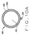
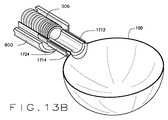
図4Aは、離脱式金属バルーン医療用デバイスのカテーテル部分の一実施形態の長手方向図を図示する。図4B〜Cは、離脱式金属バルーン医療用デバイス500の一実施形態の長手方向図を図示する。この実施形態は、取り外し可能なワイヤ404を受容するための単一の中空の円筒状部材306を有する、単一の内腔カテーテル400を含む。カテーテルの壁は、先述のように、プラスチックもしくはポリマー材料からなってもよい。別の実施形態において、カテーテルの壁は、巻き金属コイルからなる。この実施形態において、中空の円筒状部材306および取り外し可能なワイヤ404は、組み合わせて、既存の注入ワイヤと同様である。中空の円筒状部材306は、近位端において接続ポート308を含み、溶接、接着剤、または圧着等を用いて、遠位端のバルーン100に取り付けられる。図4Bに示されるように、バルーン100は、中空の円筒状部材306の外部に沿って巻き付けられる、圧縮される、およびまたは折り畳められ得る。
FIG. 4A illustrates a longitudinal view of one embodiment of the catheter portion of a detachable metal balloon medical device. 4B-C illustrate a longitudinal view of one embodiment of a detachable metal balloon
一実施形態において、圧縮されたバルーン100を有するカテーテル400は、図8A〜Eに示されるように、より大きいガイドカテーテルの内腔を通って、所望の位置まで前進させられる。圧縮されたバルーン100は、より大きいガイドカテーテルの遠位端を越えて、所望の位置に前進させられる。カテーテル400が所望の位置に定置されると、ワイヤ404は、中空の円筒状部材306から取り外され、シリンジ314等の流体源が、接続ポート308に接続され、バルーン100を膨張もしくは拡張させる。取り外し可能なワイヤ404は、ワイヤ挿入および取り外しを促進するハンドル408もしくは他のデバイスを含み得る。図4Cに示されるように、バルーン100が拡張されると、カテーテル400およびバルーン100は、拡張されたバルーン100を所望の位置に残したままに、カテーテル400を取り外すことができるように、分離することができる。一実施形態において、バルーン100が膨張もしくは拡張された後に、DC電流は、電解ワイヤ320に印加され、バルーンおよびカテーテル400との間の溶接部もしくははんだを溶解する。溶接部が溶解されると、拡張されたバルーン100が定位置のまま、カテーテル400は、取り外される。別の実施形態において、DC電流は、電解ワイヤ320に印加され、バルーンの一部分を溶解する。バルーン部分が溶解されると、カテーテル400は取り外され、拡張されたバルーン100の残りが定位置に留まる。
In one embodiment, the
図5および6は、バルーン100の収縮構成に取り付けられた離脱式バルーン送達デバイスの追加の実施形態を図示する。一実施形態において、バルーン100は、襞に折畳され、次いで、折り畳まれたバルーンの襞は、カテーテル300の周囲に巻き付けられ、バルーンは、カテーテル300に対して圧縮される。別の実施形態において、バルーン100は、襞に折り畳まれ、次いで、折り畳まれたバルーンの襞は、取り外し可能なワイヤ404の周囲に巻き付けられ、次いで、バルーンは、取り外し可能なワイヤ404に対して圧縮される。
FIGS. 5 and 6 illustrate additional embodiments of a detachable balloon delivery device attached to the deflated configuration of
種々の実施形態において、バルーン100は、カテーテル300、400に取り付けられ、次いで、襞502が形成され、次いで、襞は、カテーテルもしくは取り外し可能なワイヤ404に巻き付けられ、その上で圧縮される。別の実施形態において、バルーン100は折り畳まれ、襞502を形成し、次いで、カテーテル300、400に取り付けられ、次いで、カテーテル300、400、もしくは取り外し可能なワイヤ404の外側表面上で折り畳まれるか、または圧縮される。
In various embodiments, the
方法
本発明の方法は、バルーン100を所望の位置に送達し、バルーン100を膨張させ、拡張させ、かつバルーンおよび送達デバイスを分離するための多くのステップを含む。一実施形態において、本方法は、針を使用して動脈にアクセスし、次いで、針を通してガイドワイヤ302等のガイドワイヤを前進させるステップを含む。次に、針が取り外され、任意に、血管シースが挿入される。次いで、ガイドワイヤ302は、所望の位置までさらに前進させられる。任意に、標準的血管造影カテーテルを、ガイドワイヤ302とともに使用して、ガイドワイヤを所望の位置に前進させる。ガイドワイヤ302が適切に定置された後、標準的血管造影カテーテルは、身体から取り外される。次いで、遠位端において圧縮されたバルーン300を有するカテーテル300は、カテーテルが所望の位置に位置付けられるまで、ガイドワイヤ302の上を前進させられる。任意に、ガイドワイヤ302は、次いで、抜脱され、バルーン100は、加圧流体を用いて膨張され、拡張される。拡張されたバルーン100は、カテーテル300から分離され、カテーテルは、ガイドワイヤ302とともに取り外される。上述のように、本方法はまた、電流を電解ワイヤ320に提供して、バルーン100をカテーテルに取り付ける溶接部もしくははんだ316を溶解するか、またはバルーン自体の一部分を溶解するステップを含み得る。一実施形態において、本方法は、拡張されたバルーン100を成形するステップをさらに含む。バルーン100の成形は、隣接する血管形成バルーンもしくは閉塞型バルーン等を用いる、外部力および/または内部力の印加によって達成され得る。
Method The method of the present invention includes a number of steps for delivering the
図7A〜Eおよび8A〜Eは、血管の動脈瘤の空洞内のバルーン100の位置付け、拡張、および離脱の順序を図示する。図7A〜Eにおいて、血管702内の動脈瘤703は、バルーン100を用いて充填される。バルーン100は、加圧液体、気体、もしくはそれらの組み合わせを用いて膨張される。一実施形態において、流体は、コイル、ビーズの懸濁液、および/または薬物、薬理的活性分子、または薬学的組成物の溶液もしくは懸濁液を含有する。
7A-E and 8A-E illustrate the order of positioning, dilation, and withdrawal of the
バルーン100の拡張された形状は、治療される異常に基づく。一例において、バルーン100は、動脈瘤内腔もしくは空隙の形状によって、また、任意に、外部力の印加によって、の両方によって成形される。外部力は、血管702の内腔内で別個の隣接するバルーン(図示せず)を膨張させ、それによって、バルーン100の壁を動脈瘤に向かって押し出すことによって印加され得る。他の実施形態において、バルーン100は、特定の動脈瘤703の空洞の輪郭と一致するように非球形配向に製造される。他の形状および配向を使用し得る。バルーン100の外部表面110は、動脈瘤703の内部表面700の大部分と接触する。一実施形態において、バルーン100の外部表面110は、動脈瘤703の内部表面700の少なくとも50%と接触する。他の実施形態において、外部表面110は、内部表面700の90%以上と接触する。拡張されたバルーンは、動脈瘤の内腔701の大部分を充填する。一実施形態において、拡張されたバルーンは、動脈瘤の内腔701の少なくとも50%を充填する。
The expanded shape of the
図7Eにおいて、カテーテル300およびガイドワイヤ302は、抜脱されており、バルーン100の開口部112は、開口したままである。他の実施形態において、バルーンの開口部112は、閉口し得る。すべての実施形態において、バルーン100は、拡張されたままである。
In FIG. 7E, the
図8A〜Eに示される、別の実施形態において、誘導カテーテル800を使用して、動脈瘤703の内腔701にアクセスする。カテーテル400等の単一の内腔カテーテルは、次いで、ガイドカテーテル800を通って前進させられる。カテーテル400は、バルーン100の開口部112との通信にある。加圧流体は、拡張されたバルーン100の形状が、動脈瘤800の輪郭と厳密に一致するように、カテーテル400を介して、バルーンの内部空間もしくは空隙108内に移動させられる。一実施形態において、バルーン100は、カテーテル400への取り付け前に、特定の形状に製造される。
In another embodiment, shown in FIGS. 8A-E, a
すべての実施形態において、バルーン100の拡張された形状は、4つの要因によって決定される:1)バルーン100の製造された形状、2)膨張もしくは拡張の程度、3)動脈瘤703の寸法および形状、4)膨張もしくは拡張後の任意の印加された外部力の影響。限定でなく例として、バルーン100の製造された寸法および形状は、動脈瘤703の測定を行うことによって決定され得る。測定は、医学的画像および標準的距離指示マーカーを使用することによって行うことができる。動脈瘤を測定する他の方法も使用し得る。
In all embodiments, the expanded shape of the
別の実施形態において、バルーン100は、動脈瘤703内で操作され、インビボまたはインサイツでも構成し得る。この実施形態において、バルーン100を挿入する前に動脈瘤703の正確な輪郭を決定する必要はない。バルーン100は、内部力および/または外部力の印加によって成形される。例えば、外部力は、外部血管形成バルーンの使用によって、またはカテーテル400を通って、もしくはその周囲に挿入された工具によって印加され得る。他の実施形態において、バルーン100は、バルーンをカテーテル400から離脱させる前のステップ、またはその後のステップおいて成形され得る。
In another embodiment, the
他の実施形態において、バルーン100と同様の2つ以上のバルーンは、血管の特定のセグメントの内腔、動脈瘤内腔もしくは空隙、または他の体腔の一部分もしくはすべてを充填するように位置付けられ、膨張され得る。これらの実施形態において、事前に成形されたバルーン、未成形バルーン、可鍛性バルーン、またはそれらの組み合わせを使用し得る。すべての実施形態において、バルーンは、それらの拡張された形状を維持し、意図的ではない圧縮もしくは変形に抵抗するように位置付けられる。
In other embodiments, two or more balloons similar to
図9Aは、二重内腔カテーテル300の軸方向断面図を図示する。中空の円筒状部材304は、外側壁900および内側壁902を有し、中空の円筒状部材306は、外側壁904および内側壁906を有する。円筒状部材304および306は、互いに平行し、隣接し、電解ワイヤ320は、中空の円筒状部材306の外側壁904に沿って走行する。図9Bは、図9Aのデバイスの代替であり、図9Bは、代替的二重内腔カテーテル300の軸方向断面図を図示する。一実施形態において、中空の円筒状部材304は、第2の中空の円筒状部材306の内腔内に位置する。この実施形態において、電解ワイヤ320は、中空の円筒状部材306の外側壁904に沿って走行する。
FIG. 9A illustrates an axial cross-sectional view of a
図9Cに示される、別の実施形態において、電解ワイヤ320は、バルーンを膨張もしくは拡張するために使用される内腔326内に延在する。図9Dに示される、別の実施形態において、電解ワイヤ320は、カテーテル300の壁内に位置される。
In another embodiment, shown in FIG. 9C, the
図9Eは、バルーン100に取り付けられた二重内腔カテーテル300の軸方向断面図を図示する。バルーン100は、326との流体通信にあり、カテーテル300の壁を通って延在する電解ワイヤ320によって離脱される。
FIG. 9E illustrates an axial cross-sectional view of a
図10Aは、単一内腔カテーテル400の軸方向断面図である。示されるように、電解ワイヤ320は、中空の円筒状部材306の外側壁1000に沿って走行する。図10Bに示される、別の実施形態において、電解ワイヤ320は、円筒状部材306の壁内を走行する。図10Cは、バルーン100に取り付けられた単一内腔カテーテル400の軸方向断面図を図示する。バルーン100は、まず、中空の円筒状部材306の外側壁1000に溶接、はんだ付け、または糊付けされ、外側壁に沿って延在する電解ワイヤ320によって離脱される。
FIG. 10A is an axial cross-sectional view of a
バルーン100はまた、摩擦係合を介して送達デバイスに係合し得、バルーンの開口部もしくは首部、および送達デバイスの遠位端は、互いに嵌合するように一致するが、バルーンと送達デバイスとの間の接合(接着剤もしくははんだ等を用いる)はない。むしろ、膨張されたバルーン100および送達デバイスは、簡単に引き離される。バルーン100は、バルーンから送達カテーテルを引き離すことによって、または送達カテーテルからバルーンを押し離すことによって、送達カテーテルから離脱され得る。図13A〜Bは、医療用デバイス500の実施形態を図示し、摩擦嵌合を使用してバルーン100および送達デバイスを取り付ける。図13Aに示されるように、バルーン100の首部1714は、送達デバイス306の遠位端1712の外側上に摩擦的に係合される。この例では、バルーンが圧縮された状態で、医療用デバイス500を、ガイドカテーテル800を通過させ、次いで、送達デバイスから取り外し可能なワイヤを抜脱し、バルーン100を膨張させた。この例において、ガイドカテーテル800は、次いで、膨張されたバルーン100の壁まで前進することができ、次いで、送達デバイスを引き戻すか、またはガイドカテーテル800を前方に押し出して、膨張されたバルーンを離脱させることができる。図13Bに示されるように、弾性スリーブもしくはラップ1724は、送達デバイス306に接合することができ、次いで、バルーン100の首部1714の外側を摩擦的に係合することができ、一方、送達デバイスの遠位端1712は、バルーン100の首部1714の内部表面を同時に摩擦的に係合する。
バルーンの外部表面が、ニチノールもしくは繊維から作製される、線形もしくは分岐である複数の突起部を含むバルーン。 A balloon wherein the outer surface of the balloon includes a plurality of protrusions that are linear or branched, made from nitinol or fibers.
突起部が0.01μm〜約57μmの範囲の長さであるバルーン。 A balloon with a protrusion having a length in the range of 0.01 μm to about 57 μm.
本発明のデバイスおよび方法が、種々の実施形態の形態(そのいくつかのみが上記に例証され、説明される)に組み込むことが可能であることを理解されたい。本発明は、その精神または本質的な特性から逸脱することなく、他の特定の形態において具体化され得る。説明される実施形態は、すべての点で、制限ではなく例証としてみなされるものであり、本発明の範囲は、したがって、先述の説明よりはむしろ、付属の請求項によって示される。請求項の等価の意味および範囲内に入るすべての変更は、それらの範囲内に受け入れられるものとする。 It should be understood that the devices and methods of the present invention can be incorporated into the form of various embodiments, only some of which are illustrated and described above. The present invention may be embodied in other specific forms without departing from its spirit or essential characteristics. The described embodiments are to be considered in all respects as illustrative and not restrictive, and the scope of the invention is therefore indicated by the appended claims rather than by the foregoing description. All changes that come within the meaning and range of equivalency of the claims are to be embraced within their scope.
Claims (88)
前記バルーンに取り付けられたカテーテルであって、前記カテーテルは、内腔を画定する円筒状部材を有し、前記円筒状部材が、近位端および遠位端を有し、前記カテーテルが、前記近位端の流体源からの流体を、前記遠位端の前記バルーンに送達するように寸法決定される、カテーテルと、
を備える、医療用デバイス。 A compressed single-lobe expandable metal balloon having a wall having an interior surface, an exterior surface, and an opening in the wall that allows passage of gas or fluid into the balloon;
A catheter attached to the balloon, wherein the catheter has a cylindrical member defining a lumen, the cylindrical member has a proximal end and a distal end, and the catheter has the proximal end. A catheter sized to deliver fluid from a distal fluid source to the balloon at the distal end;
A medical device comprising:
取り付けられたカテーテルを使用して、圧縮された金属バルーンを所望の位置に位置付けるステップと、
流体を用いて、前記圧縮されたバルーンを膨張させ、拡張するステップと、
前記拡張されたバルーンを前記カテーテルから分離するステップと、
前記バルーンを前記所望の位置で拡張したまま、前記カテーテルを取り外すステップと、
を含む、方法。 A method of filling a portion of a vascular lumen, an aneurysm, or another vascular abnormality using a metal balloon, comprising:
Using the attached catheter to position the compressed metal balloon in the desired location;
Inflating and expanding the compressed balloon with a fluid;
Separating the expanded balloon from the catheter;
Removing the catheter while the balloon is inflated at the desired position;
Including a method.
薬物、薬理活性分子、または薬学的組成物が、前記バルーンを前記所望の位置に位置付ける前に、前記バルーン壁の前記外部表面の前記多孔性外側層内に移動するように、前記バルーンの少なくとも一部分を、薬物、薬理活性分子、または薬学的組成物の溶液もしくは懸濁液内に定置するステップをさらに含む、請求項49に記載の方法。 The outer surface of the balloon comprises a porous outer layer having pores with diameters ranging from about 0.05 μm to about 100 μm, the method comprising:
At least a portion of the balloon such that a drug, pharmacologically active molecule, or pharmaceutical composition moves into the porous outer layer of the outer surface of the balloon wall prior to positioning the balloon in the desired location. 50. The method of claim 49, further comprising placing the in a solution or suspension of the drug, pharmacologically active molecule, or pharmaceutical composition.
圧縮されたバルーンを、カテーテルを使用して血管系の所望の位置に位置付けるステップと、
流体を用いて、前記バルーンを膨張させ、拡張させるステップと、
前記バルーンを前記所望の位置で拡張させたまま、前記カテーテルを前記バルーンから離脱させるステップと、
を含む、方法。 A method of occluding a blood vessel or treating a vascular abnormality using a ductile metal balloon comprising:
Positioning the compressed balloon at a desired location in the vasculature using a catheter;
Inflating and expanding the balloon using a fluid;
Detaching the catheter from the balloon while the balloon is expanded at the desired position;
Including a method.
前記圧縮されたバルーンを、カテーテルを使用して前記血管系内の所望の位置に位置付ける前に、薬物または薬理活性分子の溶液もしくは懸濁液を前記バルーンの外部表面の前記多孔性外側層と接触させて定置するステップと、
前記薬物または薬理活性分子を前記所望の位置に送達するステップと、をさらに含む、請求項62に記載の方法。 The balloon outer surface comprises a porous outer layer having pores with diameters ranging from about 0.05 μm to about 100 μm, the method comprising:
Contact the solution or suspension of a drug or pharmacologically active molecule with the porous outer layer on the outer surface of the balloon before positioning the compressed balloon at a desired location within the vasculature using a catheter. Step to be fixed,
64. The method of claim 62, further comprising delivering the drug or pharmacologically active molecule to the desired location.
針を用いて血管にアクセスするステップと、
前記針を介してガイドワイヤを挿入するステップと、
前記針を取り外すステップと、
前記ガイドワイヤを前記血管系内の所望の位置に位置付けるステップと、
圧縮されたバルーンをカテーテルを使用して前記血管系内の所望の位置に位置付けるステップと、
前記ガイドワイヤを取り外すステップと、
流体を用いて、前記バルーンを膨張させ、拡張させるステップと、
前記バルーンを前記所望の位置で拡張させたまま、前記カテーテルを前記バルーンから離脱させるステップと、
前記カテーテルを取り外すステップと、
を含む、方法。 A method of occluding a blood vessel or treating an aneurysm or other vascular abnormality using a ductile metal balloon comprising:
Accessing a blood vessel using a needle;
Inserting a guide wire through the needle;
Removing the needle;
Positioning the guidewire at a desired location within the vasculature;
Positioning the compressed balloon at a desired location within the vasculature using a catheter;
Removing the guide wire;
Inflating and expanding the balloon using a fluid;
Detaching the catheter from the balloon while the balloon is expanded at the desired position;
Removing the catheter;
Including a method.
Applications Claiming Priority (3)
| Application Number | Priority Date | Filing Date | Title |
|---|---|---|---|
| US201161433305P | 2011-01-17 | 2011-01-17 | |
| US61/433,305 | 2011-01-17 | ||
| PCT/US2012/021620 WO2012099909A2 (en) | 2011-01-17 | 2012-01-17 | Detachable metal balloon delivery device and method |
Related Child Applications (1)
| Application Number | Title | Priority Date | Filing Date |
|---|---|---|---|
| JP2017203411A Division JP6463817B2 (en) | 2011-01-17 | 2017-10-20 | Detachable metal balloon delivery device and method |
Publications (3)
| Publication Number | Publication Date |
|---|---|
| JP2014508574A true JP2014508574A (en) | 2014-04-10 |
| JP2014508574A5 JP2014508574A5 (en) | 2015-03-05 |
| JP6559396B2 JP6559396B2 (en) | 2019-08-14 |
Family
ID=46516296
Family Applications (8)
| Application Number | Title | Priority Date | Filing Date |
|---|---|---|---|
| JP2013549436A Active JP6546718B2 (en) | 2011-01-17 | 2012-01-17 | Block stent device and method of use |
| JP2013549617A Active JP6559396B2 (en) | 2011-01-17 | 2012-01-17 | Detachable metal balloon delivery device and method |
| JP2013549618A Active JP6522279B2 (en) | 2011-01-17 | 2012-01-17 | Ball stent device and method of use |
| JP2017202670A Active JP6463816B2 (en) | 2011-01-17 | 2017-10-19 | Block stent device and method of use |
| JP2017203411A Active JP6463817B2 (en) | 2011-01-17 | 2017-10-20 | Detachable metal balloon delivery device and method |
| JP2017204554A Active JP6463819B2 (en) | 2011-01-17 | 2017-10-23 | Ball stent device and method of use |
| JP2018113623A Pending JP2018158136A (en) | 2011-01-17 | 2018-06-14 | Expandable body device and method of use |
| JP2020162388A Pending JP2020203163A (en) | 2011-01-17 | 2020-09-28 | Medical device, system, and kit |
Family Applications Before (1)
| Application Number | Title | Priority Date | Filing Date |
|---|---|---|---|
| JP2013549436A Active JP6546718B2 (en) | 2011-01-17 | 2012-01-17 | Block stent device and method of use |
Family Applications After (6)
| Application Number | Title | Priority Date | Filing Date |
|---|---|---|---|
| JP2013549618A Active JP6522279B2 (en) | 2011-01-17 | 2012-01-17 | Ball stent device and method of use |
| JP2017202670A Active JP6463816B2 (en) | 2011-01-17 | 2017-10-19 | Block stent device and method of use |
| JP2017203411A Active JP6463817B2 (en) | 2011-01-17 | 2017-10-20 | Detachable metal balloon delivery device and method |
| JP2017204554A Active JP6463819B2 (en) | 2011-01-17 | 2017-10-23 | Ball stent device and method of use |
| JP2018113623A Pending JP2018158136A (en) | 2011-01-17 | 2018-06-14 | Expandable body device and method of use |
| JP2020162388A Pending JP2020203163A (en) | 2011-01-17 | 2020-09-28 | Medical device, system, and kit |
Country Status (13)
| Country | Link |
|---|---|
| US (9) | US11090176B2 (en) |
| EP (5) | EP2665441B1 (en) |
| JP (8) | JP6546718B2 (en) |
| KR (7) | KR101965456B1 (en) |
| CN (6) | CN103476349B (en) |
| AU (8) | AU2012207618B2 (en) |
| BR (3) | BR112013018117B1 (en) |
| CA (3) | CA2822311C (en) |
| ES (4) | ES2676661T3 (en) |
| HK (1) | HK1246131A1 (en) |
| IL (6) | IL227440B (en) |
| RU (6) | RU2695288C2 (en) |
| WO (3) | WO2012099704A2 (en) |
Cited By (3)
| Publication number | Priority date | Publication date | Assignee | Title |
|---|---|---|---|---|
| JP2014509881A (en) * | 2011-01-17 | 2014-04-24 | ノビタ・セラピューティクス・リミテッド・ライアビリティ・カンパニー | Ball stent device and method of use |
| JP2019181186A (en) * | 2018-03-30 | 2019-10-24 | デピュイ・シンセス・プロダクツ・インコーポレイテッド | Helical balloon assist device and method for using the same |
| JP2022509985A (en) * | 2018-11-30 | 2022-01-25 | アクパス メディカル(ジャシン)カンパニー リミテッド | Medical tube body and its preparation method |
Families Citing this family (126)
| Publication number | Priority date | Publication date | Assignee | Title |
|---|---|---|---|---|
| US8425549B2 (en) | 2002-07-23 | 2013-04-23 | Reverse Medical Corporation | Systems and methods for removing obstructive matter from body lumens and treating vascular defects |
| CA2758946C (en) | 2004-05-25 | 2014-10-21 | Tyco Healthcare Group Lp | Vascular stenting for aneurysms |
| US9675476B2 (en) | 2004-05-25 | 2017-06-13 | Covidien Lp | Vascular stenting for aneurysms |
| JP2008502378A (en) | 2004-05-25 | 2008-01-31 | チェストナット メディカル テクノロジーズ インコーポレイテッド | Flexible vascular closure device |
| US8152833B2 (en) | 2006-02-22 | 2012-04-10 | Tyco Healthcare Group Lp | Embolic protection systems having radiopaque filter mesh |
| EP2460477B1 (en) | 2008-04-21 | 2018-04-11 | Covidien LP | Braid-ball embolic devices and delivery systems |
| US10716573B2 (en) | 2008-05-01 | 2020-07-21 | Aneuclose | Janjua aneurysm net with a resilient neck-bridging portion for occluding a cerebral aneurysm |
| US11357511B2 (en) | 2008-05-01 | 2022-06-14 | Aneuclose Llc | Intrasacular aneurysm occlusion device with globular first configuration and bowl-shaped second configuration |
| US10028747B2 (en) | 2008-05-01 | 2018-07-24 | Aneuclose Llc | Coils with a series of proximally-and-distally-connected loops for occluding a cerebral aneurysm |
| US12004750B2 (en) | 2008-05-01 | 2024-06-11 | Aneuclose Llc | Methods for creating an expandable two-part intrasacular aneurysm occlusion device from a tubular mesh |
| US11583289B2 (en) | 2008-05-01 | 2023-02-21 | Aneuclose Llc | Aneurysm-occluding mesh ribbon with a series of loops or segments having distal-to-proximal variation in size, shape, and/or orientation |
| US11484322B2 (en) | 2018-01-03 | 2022-11-01 | Aneuclose Llc | Aneurysm neck bridge with a closeable opening or lumen through which embolic material is inserted into the aneurysm sac |
| US11471164B2 (en) | 2008-05-01 | 2022-10-18 | Aneuclose Llc | Methods of occluding a cerebral aneurysm by inserting embolic members or material into an intrasacular implant |
| US11464518B2 (en) | 2008-05-01 | 2022-10-11 | Aneuclose Llc | Proximal concave neck bridge with central lumen and distal net for occluding cerebral aneurysms |
| US9675482B2 (en) | 2008-05-13 | 2017-06-13 | Covidien Lp | Braid implant delivery systems |
| US8409269B2 (en) | 2009-12-21 | 2013-04-02 | Covidien Lp | Procedures for vascular occlusion |
| US9358140B1 (en) | 2009-11-18 | 2016-06-07 | Aneuclose Llc | Stent with outer member to embolize an aneurysm |
| US8974512B2 (en) | 2010-09-10 | 2015-03-10 | Medina Medical, Inc. | Devices and methods for the treatment of vascular defects |
| US8998947B2 (en) | 2010-09-10 | 2015-04-07 | Medina Medical, Inc. | Devices and methods for the treatment of vascular defects |
| US9351859B2 (en) | 2010-12-06 | 2016-05-31 | Covidien Lp | Vascular remodeling device |
| US11484318B2 (en) | 2011-01-17 | 2022-11-01 | Artio Medical, Inc. | Expandable body device and method of use |
| US9089332B2 (en) | 2011-03-25 | 2015-07-28 | Covidien Lp | Vascular remodeling device |
| BR112013028603A2 (en) | 2011-05-11 | 2017-01-17 | Covidien Lp | vascular remodeling device |
| US9060886B2 (en) | 2011-09-29 | 2015-06-23 | Covidien Lp | Vascular remodeling device |
| US9072620B2 (en) | 2011-11-04 | 2015-07-07 | Covidien Lp | Protuberant aneurysm bridging device deployment method |
| EP2806825B1 (en) | 2012-01-17 | 2018-08-22 | Metactive Medical, Inc. | Expandable body device |
| US9011480B2 (en) | 2012-01-20 | 2015-04-21 | Covidien Lp | Aneurysm treatment coils |
| US10182932B2 (en) | 2012-02-21 | 2019-01-22 | Allurion Technologies, Inc. | Methods and devices for deploying and releasing a temporary implant within the body |
| US9452070B2 (en) | 2012-10-31 | 2016-09-27 | Covidien Lp | Methods and systems for increasing a density of a region of a vascular device |
| EP2919668A2 (en) | 2012-11-13 | 2015-09-23 | Covidien LP | Occlusive devices |
| US20140142620A1 (en) * | 2012-11-19 | 2014-05-22 | Cook Medical Technologies Llc | Degradable balloon device and method for closure of openings in a tissue wall |
| RU2706374C2 (en) * | 2013-03-15 | 2019-11-18 | Метэктив Медикал, Инк. | Device in the form of the expandable body and method of its application |
| WO2014145012A2 (en) | 2013-03-15 | 2014-09-18 | Covidien Lp | Delivery and detachment mechanisms for vascular implants |
| US10736758B2 (en) | 2013-03-15 | 2020-08-11 | Covidien | Occlusive device |
| US9795400B2 (en) | 2013-11-13 | 2017-10-24 | Covidien Lp | Galvanically assisted attachment of medical devices to thrombus |
| US9987014B2 (en) | 2014-02-06 | 2018-06-05 | Boston Scientific Scimed, Inc. | Occlusion device |
| US11076860B2 (en) | 2014-03-31 | 2021-08-03 | DePuy Synthes Products, Inc. | Aneurysm occlusion device |
| US11154302B2 (en) | 2014-03-31 | 2021-10-26 | DePuy Synthes Products, Inc. | Aneurysm occlusion device |
| US9713475B2 (en) | 2014-04-18 | 2017-07-25 | Covidien Lp | Embolic medical devices |
| CN106456183B (en) | 2014-04-30 | 2019-09-20 | Cerus血管内设备有限公司 | Locking device |
| US20150330158A1 (en) * | 2014-05-19 | 2015-11-19 | Crescent Point Energy Corp. | Apparatuses, systems, and methods for injecting fluids into a subterranean formation |
| CN105213076A (en) * | 2014-06-12 | 2016-01-06 | 微创心脉医疗科技(上海)有限公司 | A kind of artificial tumor neck and preparation method thereof |
| US8900304B1 (en) | 2014-06-17 | 2014-12-02 | Abdulrazzaq Alobaid | Kyphoplasty cement encapsulation balloon |
| US9579427B2 (en) | 2014-06-28 | 2017-02-28 | Cordis Corporation | Thin-film composite retrievable endovascular devices and method of use |
| US9918718B2 (en) * | 2014-08-08 | 2018-03-20 | DePuy Synthes Products, Inc. | Embolic coil delivery system with retractable mechanical release mechanism |
| US9814466B2 (en) | 2014-08-08 | 2017-11-14 | Covidien Lp | Electrolytic and mechanical detachment for implant delivery systems |
| RU2721288C2 (en) * | 2014-09-17 | 2020-05-18 | Метэктив Медикал, Инк. | Medical device for saccular aneurysm treatment |
| EP3240508B1 (en) * | 2014-12-31 | 2020-06-24 | Endologix, Inc. | Dual inflatable arterial prosthesis |
| US10314593B2 (en) | 2015-09-23 | 2019-06-11 | Covidien Lp | Occlusive devices |
| US10478194B2 (en) | 2015-09-23 | 2019-11-19 | Covidien Lp | Occlusive devices |
| CN106618660A (en) * | 2015-10-29 | 2017-05-10 | 西安东澳生物科技有限公司 | Self-crawling blood vessel blocking device |
| US10080875B2 (en) * | 2015-12-01 | 2018-09-25 | Medtronic Vascular, Inc. | Handle component for providing a pressurized material |
| CA3005686A1 (en) | 2015-12-07 | 2017-06-15 | Cerus Endovascular Limited | Occlusion device |
| WO2017127692A1 (en) * | 2016-01-22 | 2017-07-27 | Fort Wayne Metals Research Products Corp. | Woven or braided tubular metal construct |
| US10980545B2 (en) | 2016-02-10 | 2021-04-20 | Microvention, Inc. | Devices for vascular occlusion |
| WO2017153603A1 (en) | 2016-03-11 | 2017-09-14 | Cerus Endovascular Limited | Occlusion device |
| WO2017165833A1 (en) | 2016-03-24 | 2017-09-28 | Covidien Lp | Thin wall constructions for vascular flow diversion |
| CN105854161B (en) * | 2016-06-21 | 2022-06-24 | 中国福利会国际和平妇幼保健院 | Cervical anti-adhesion dilating rod and preparation method and application thereof |
| US10828039B2 (en) | 2016-06-27 | 2020-11-10 | Covidien Lp | Electrolytic detachment for implantable devices |
| US10828037B2 (en) | 2016-06-27 | 2020-11-10 | Covidien Lp | Electrolytic detachment with fluid electrical connection |
| US11051822B2 (en) | 2016-06-28 | 2021-07-06 | Covidien Lp | Implant detachment with thermal activation |
| US10478195B2 (en) | 2016-08-04 | 2019-11-19 | Covidien Lp | Devices, systems, and methods for the treatment of vascular defects |
| US10576099B2 (en) | 2016-10-21 | 2020-03-03 | Covidien Lp | Injectable scaffold for treatment of intracranial aneurysms and related technology |
| WO2018156833A1 (en) | 2017-02-23 | 2018-08-30 | DePuy Synthes Products, Inc. | Aneurysm device and delivery system |
| ES2971315T3 (en) | 2017-08-21 | 2024-06-04 | Cerus Endovascular Ltd | Occlusion device |
| US10675036B2 (en) | 2017-08-22 | 2020-06-09 | Covidien Lp | Devices, systems, and methods for the treatment of vascular defects |
| CN110753521A (en) * | 2017-09-01 | 2020-02-04 | 美它克医药公司 | Medical devices including a detachable balloon and methods of making and using |
| KR102042450B1 (en) * | 2017-09-05 | 2019-11-08 | 한양대학교 산학협력단 | Catheter ballon coated with conductive material for multi-layered and the fabrication method thereof |
| JP6862606B2 (en) * | 2017-09-14 | 2021-04-21 | アクセスクロージャー,インク. | Device to place expandable support |
| WO2019068074A1 (en) * | 2017-09-29 | 2019-04-04 | Musc Foundation For Research Development | Expandable device |
| US10905430B2 (en) | 2018-01-24 | 2021-02-02 | DePuy Synthes Products, Inc. | Aneurysm device and delivery system |
| US11065009B2 (en) | 2018-02-08 | 2021-07-20 | Covidien Lp | Vascular expandable devices |
| US11065136B2 (en) | 2018-02-08 | 2021-07-20 | Covidien Lp | Vascular expandable devices |
| WO2019165449A1 (en) | 2018-02-26 | 2019-08-29 | Allurion Technologies, Inc. | Automatic-sealing balloon-filling catheter system |
| EP3787530B1 (en) * | 2018-05-03 | 2024-07-10 | Medtronic Vascular, Inc. | Tip assemblies and systems for fracturing a frame of a deployed prosthesis |
| US11058430B2 (en) | 2018-05-25 | 2021-07-13 | DePuy Synthes Products, Inc. | Aneurysm device and delivery system |
| US11596412B2 (en) | 2018-05-25 | 2023-03-07 | DePuy Synthes Products, Inc. | Aneurysm device and delivery system |
| US10939915B2 (en) | 2018-05-31 | 2021-03-09 | DePuy Synthes Products, Inc. | Aneurysm device and delivery system |
| CN108671363B (en) * | 2018-06-01 | 2021-05-04 | 湖南瀚德微创医疗科技有限公司 | Urethral dilator with induction device |
| CN114376777B (en) | 2018-07-06 | 2024-02-02 | 安瑞仁科技公司 | Binary fluid control valve system |
| JP2021533189A (en) | 2018-08-03 | 2021-12-02 | ネクテロ・メディカル・インコーポレイテッド | Purified pentagalloyl glucose and delivery device |
| US11051825B2 (en) | 2018-08-08 | 2021-07-06 | DePuy Synthes Products, Inc. | Delivery system for embolic braid |
| US10912569B2 (en) | 2018-08-22 | 2021-02-09 | Covidien Lp | Aneurysm treatment coils and associated systems and methods of use |
| US10905432B2 (en) | 2018-08-22 | 2021-02-02 | Covidien Lp | Aneurysm treatment coils and associated systems and methods of use |
| KR102138632B1 (en) * | 2018-08-28 | 2020-07-28 | 인제대학교 산학협력단 | Stent structure and surgical instrument for stent including the structure |
| US11123077B2 (en) | 2018-09-25 | 2021-09-21 | DePuy Synthes Products, Inc. | Intrasaccular device positioning and deployment system |
| US11076861B2 (en) | 2018-10-12 | 2021-08-03 | DePuy Synthes Products, Inc. | Folded aneurysm treatment device and delivery method |
| US11406392B2 (en) | 2018-12-12 | 2022-08-09 | DePuy Synthes Products, Inc. | Aneurysm occluding device for use with coagulating agents |
| BR112021011198A2 (en) * | 2018-12-13 | 2021-08-31 | Allurion Technologies, Inc. | MEDICAL DEVICE FOR POSITIONING IN A PATIENT, FLUID DISTRIBUTION SYSTEM FOR POSITIONING A MEDICAL DEVICE IN A PATIENT AND DELIVERY A FLUID TO A CLOSED RESERVOIR IN THE DEVICE AND FLUID DISTRIBUTION SYSTEM TO PLACE A MEDICAL DEVICE IN A PATIENT AND DELIVER A FLUID TO A CLOSED RESERVOIR ON THE DEVICE |
| EP3897409A2 (en) | 2018-12-17 | 2021-10-27 | Covidien LP | Devices and systems for the treatment of vascular defects |
| US11272939B2 (en) | 2018-12-18 | 2022-03-15 | DePuy Synthes Products, Inc. | Intrasaccular flow diverter for treating cerebral aneurysms |
| WO2020146840A1 (en) * | 2019-01-10 | 2020-07-16 | Northeastern University | Titanium dioxide coatings for medical devices made by atomic layer deposition |
| KR102213798B1 (en) * | 2019-01-14 | 2021-02-09 | 계명대학교 산학협력단 | A catheter inserted into artery of the arm to prevent abdominal bleeding and use method thereof |
| US11134953B2 (en) | 2019-02-06 | 2021-10-05 | DePuy Synthes Products, Inc. | Adhesive cover occluding device for aneurysm treatment |
| CN109901146B (en) * | 2019-03-15 | 2023-03-14 | 西安电子科技大学 | Hemispherical array and differential angle decoupling method based on spiral distribution |
| US11337706B2 (en) | 2019-03-27 | 2022-05-24 | DePuy Synthes Products, Inc. | Aneurysm treatment device |
| US11278292B2 (en) | 2019-05-21 | 2022-03-22 | DePuy Synthes Products, Inc. | Inverting braided aneurysm treatment system and method |
| US11602350B2 (en) | 2019-12-05 | 2023-03-14 | DePuy Synthes Products, Inc. | Intrasaccular inverting braid with highly flexible fill material |
| US10653425B1 (en) | 2019-05-21 | 2020-05-19 | DePuy Synthes Products, Inc. | Layered braided aneurysm treatment device |
| US11607226B2 (en) | 2019-05-21 | 2023-03-21 | DePuy Synthes Products, Inc. | Layered braided aneurysm treatment device with corrugations |
| US11497504B2 (en) | 2019-05-21 | 2022-11-15 | DePuy Synthes Products, Inc. | Aneurysm treatment with pushable implanted braid |
| US11413046B2 (en) | 2019-05-21 | 2022-08-16 | DePuy Synthes Products, Inc. | Layered braided aneurysm treatment device |
| US11672542B2 (en) | 2019-05-21 | 2023-06-13 | DePuy Synthes Products, Inc. | Aneurysm treatment with pushable ball segment |
| CN110584770A (en) * | 2019-09-29 | 2019-12-20 | 上海凯利泰医疗科技股份有限公司 | High-pressure vertebral body expansion balloon and preparation method thereof |
| WO2021092619A1 (en) | 2019-11-04 | 2021-05-14 | Covidien Lp | Systems and methods for treating aneurysms |
| WO2021127567A1 (en) * | 2019-12-18 | 2021-06-24 | Terumo Corporation | Method and apparatus for minimizing excess drug delivery |
| US11457926B2 (en) | 2019-12-18 | 2022-10-04 | DePuy Synthes Products, Inc. | Implant having an intrasaccular section and intravascular section |
| CN113081125B (en) * | 2019-12-23 | 2022-07-26 | 微创神通医疗科技(上海)有限公司 | Aneurysm plugging device |
| US11406404B2 (en) | 2020-02-20 | 2022-08-09 | Cerus Endovascular Limited | Clot removal distal protection methods |
| US12004627B2 (en) * | 2020-03-20 | 2024-06-11 | Crystal International (Group) | Shock absorbing cosmetic compact |
| US11931041B2 (en) | 2020-05-12 | 2024-03-19 | Covidien Lp | Devices, systems, and methods for the treatment of vascular defects |
| RU199400U1 (en) * | 2020-05-16 | 2020-08-31 | Государственное бюджетное учреждение здравоохранения города Москвы «Научно-исследовательский институт скорой помощи им. Н.В. Склифосовского Департамента здравоохранения города Москвы» (ГБУЗ "НИИ СП ИМ. Н.В. СКЛИФОСОВСКОГО ДЗМ") | DEVICE FOR EXTERNAL INTESTINAL FISTORAL TREATMENT |
| US11224436B2 (en) * | 2020-05-21 | 2022-01-18 | Cesar Munoz | Hemorrhage control device |
| KR20210150657A (en) * | 2020-06-03 | 2021-12-13 | 주식회사 제노스 | Balloon catheter of drug-coated type |
| CN112206058B (en) * | 2020-10-21 | 2022-10-25 | 湖南雅美医疗美容医院有限公司 | Skin expansion device for burn plastic surgery |
| KR102531638B1 (en) * | 2020-12-15 | 2023-05-10 | 인제대학교 산학협력단 | Balloon device for space maintenance and drug injection in shoulder joint |
| WO2022170187A1 (en) * | 2021-02-05 | 2022-08-11 | Pyne Devaraj | Detachable balloon embolization device and methods |
| US20220280077A1 (en) * | 2021-03-08 | 2022-09-08 | Douglas Stockton | Glucose electrolysis method and apparatus |
| KR102337067B1 (en) | 2021-06-25 | 2021-12-07 | 전남대학교산학협력단 | Medical midline catheter |
| CN113559395B (en) * | 2021-07-27 | 2023-04-25 | 西藏自治区人民政府驻成都办事处医院 | Balloon catheter special for BRTO and application method |
| EP4384099A2 (en) * | 2021-08-11 | 2024-06-19 | Medtronic, Inc. | Apparatus and system for creating chronically stable atrial shunt |
| CN113995531B (en) * | 2021-12-09 | 2024-05-03 | 南通市妇幼保健院 | Anti-biting device for obstetric and gynecologic childbirth operation |
| WO2023114349A1 (en) * | 2021-12-17 | 2023-06-22 | The University Of Toledo | Bore embolization catheter |
| US11957356B2 (en) | 2022-02-24 | 2024-04-16 | NV MEDTECH, Inc. | Methods and apparatus for stent assisted aneurysm coiling |
| CN114682471B (en) * | 2022-03-08 | 2022-11-29 | 吉林大学 | Ultrasonic control device and detection system |
| CN114948060B (en) * | 2022-07-27 | 2022-11-11 | 北京久事神康医疗科技有限公司 | Device for inhibiting expansion or rupture of aneurysm |
Citations (17)
| Publication number | Priority date | Publication date | Assignee | Title |
|---|---|---|---|---|
| US4638803A (en) * | 1982-09-30 | 1987-01-27 | Rand Robert W | Medical apparatus for inducing scar tissue formation in a body |
| US4819637A (en) * | 1987-09-01 | 1989-04-11 | Interventional Therapeutics Corporation | System for artificial vessel embolization and devices for use therewith |
| JPH0413155U (en) * | 1990-05-25 | 1992-02-03 | ||
| US6346117B1 (en) * | 2000-03-02 | 2002-02-12 | Prodesco, Inc. | Bag for use in the intravascular treatment of saccular aneurysms |
| US20020169473A1 (en) * | 1999-06-02 | 2002-11-14 | Concentric Medical, Inc. | Devices and methods for treating vascular malformations |
| JP2004512893A (en) * | 2000-10-27 | 2004-04-30 | パルモンクス | Methods and devices for occlusion and aspiration of lung tissue segments |
| JP2004520881A (en) * | 2000-12-27 | 2004-07-15 | ボストン サイエンティフィック リミテッド | Occlusion balloon with selective permeability and high inflation |
| JP2004536672A (en) * | 2001-07-31 | 2004-12-09 | アドヴァンスド バイオ プロスセティック サーフェシーズ リミテッド | Balloon catheter having metal balloon and method of manufacturing the same |
| WO2007006139A1 (en) * | 2005-07-12 | 2007-01-18 | Smart Biotech Inc. | Aneurysm occlusion device |
| US20070150041A1 (en) * | 2005-12-22 | 2007-06-28 | Nellix, Inc. | Methods and systems for aneurysm treatment using filling structures |
| JP2007236472A (en) * | 2006-03-06 | 2007-09-20 | Terumo Corp | Catheter |
| JP2007533360A (en) * | 2003-06-13 | 2007-11-22 | トライバスキュラー・インコーポレイテッド | An inflatable and expandable implant suitable for implantation into the human body, an inflatable and expandable implant suitable for raising the local internal temperature of the human body, and a valving assembly that controls the flow of body fluid in the tubular partial lumen of the human body And an inflatable and expandable implant suitable for implantation into the human body at the implantation site and suitable for removal from the implantation site |
| US20070288083A1 (en) * | 2006-05-12 | 2007-12-13 | Hines Richard A | Exclusion Device and System For Delivery |
| JP2008526372A (en) * | 2005-01-07 | 2008-07-24 | セロノバ バイオサイエンシーズ, インコーポレイテッド | 3D implantable bone support |
| WO2009135166A2 (en) * | 2008-05-02 | 2009-11-05 | Sequent Medical Inc. | Filamentary devices for treatment of vascular defects |
| WO2010028310A2 (en) * | 2008-09-05 | 2010-03-11 | Cardiopolymers, Inc | Apparatus and method for capsule formation in tissue |
| US20100241178A1 (en) * | 2008-06-02 | 2010-09-23 | Loma Vista Medical, Inc. | Inflatable medical devices |
Family Cites Families (169)
| Publication number | Priority date | Publication date | Assignee | Title |
|---|---|---|---|---|
| US3459880A (en) * | 1967-09-19 | 1969-08-05 | Jack A Erdle | Flexible bus bar |
| US3794268A (en) | 1970-12-29 | 1974-02-26 | Tee Pak Inc | Tubular films or webs |
| US4471779A (en) | 1976-08-25 | 1984-09-18 | Becton, Dickinson And Company | Miniature balloon catheter |
| US4341218A (en) | 1978-05-30 | 1982-07-27 | University Of California | Detachable balloon catheter |
| US4346712A (en) | 1979-04-06 | 1982-08-31 | Kuraray Company, Ltd. | Releasable balloon catheter |
| US4395806A (en) * | 1980-05-08 | 1983-08-02 | Sorenson Research Co., Inc. | Method of manufacturing a detachable balloon catheter assembly |
| US4311146A (en) * | 1980-05-08 | 1982-01-19 | Sorenson Research Co., Inc. | Detachable balloon catheter apparatus and method |
| US4364392A (en) * | 1980-12-04 | 1982-12-21 | Wisconsin Alumni Research Foundation | Detachable balloon catheter |
| US4416028A (en) | 1981-01-22 | 1983-11-22 | Ingvar Eriksson | Blood vessel prosthesis |
| US4441495A (en) | 1982-08-16 | 1984-04-10 | Becton, Dickinson And Company | Detachable balloon catheter device and method of use |
| US4517979A (en) * | 1983-07-14 | 1985-05-21 | Cordis Corporation | Detachable balloon catheter |
| US4770067A (en) * | 1987-06-08 | 1988-09-13 | Kollmorgen Corporation | Method of manufacturing surgical cutting tools for thermally aided surgery |
| US5527337A (en) * | 1987-06-25 | 1996-06-18 | Duke University | Bioabsorbable stent and method of making the same |
| US4808773A (en) * | 1987-10-01 | 1989-02-28 | Digital Equipment Corporation | Low impedance cable |
| EP0352325A4 (en) * | 1988-01-12 | 1990-05-14 | Ki Nii Nejrokhirurgii | Occluding device. |
| US5354295A (en) | 1990-03-13 | 1994-10-11 | Target Therapeutics, Inc. | In an endovascular electrolytically detachable wire and tip for the formation of thrombus in arteries, veins, aneurysms, vascular malformations and arteriovenous fistulas |
| US6425893B1 (en) | 1990-03-13 | 2002-07-30 | The Regents Of The University Of California | Method and apparatus for fast electrolytic detachment of an implant |
| US5167627A (en) * | 1990-09-13 | 1992-12-01 | Abbott Laboratories | Stoma creator gastrostomy device and method for placement of a feeding tube |
| US5282847A (en) * | 1991-02-28 | 1994-02-01 | Medtronic, Inc. | Prosthetic vascular grafts with a pleated structure |
| US5222970A (en) | 1991-09-06 | 1993-06-29 | William A. Cook Australia Pty. Ltd. | Method of and system for mounting a vascular occlusion balloon on a delivery catheter |
| US5327885A (en) | 1991-10-08 | 1994-07-12 | Griffith James M | Combination catheter for invasive probe delivery and balloon dilation |
| EP0549100A1 (en) | 1991-12-20 | 1993-06-30 | Interventional Technologies Inc | Catheter balloon formed from a polymeric composite |
| US5250059A (en) | 1992-01-22 | 1993-10-05 | Devices For Vascular Intervention, Inc. | Atherectomy catheter having flexible nose cone |
| US5382261A (en) * | 1992-09-01 | 1995-01-17 | Expandable Grafts Partnership | Method and apparatus for occluding vessels |
| US5370691A (en) | 1993-01-26 | 1994-12-06 | Target Therapeutics, Inc. | Intravascular inflatable stent |
| CA2114988A1 (en) * | 1993-02-05 | 1994-08-06 | Matthew O'boyle | Ultrasonic angioplasty balloon catheter |
| US5499995C1 (en) * | 1994-05-25 | 2002-03-12 | Paul S Teirstein | Body passageway closure apparatus and method of use |
| US5522836A (en) * | 1994-06-27 | 1996-06-04 | Target Therapeutics, Inc. | Electrolytically severable coil assembly with movable detachment point |
| US5752522A (en) | 1995-05-04 | 1998-05-19 | Cardiovascular Concepts, Inc. | Lesion diameter measurement catheter and method |
| US6045557A (en) | 1995-11-10 | 2000-04-04 | Baxter International Inc. | Delivery catheter and method for positioning an intraluminal graft |
| US5843117A (en) | 1996-02-14 | 1998-12-01 | Inflow Dynamics Inc. | Implantable vascular and endoluminal stents and process of fabricating the same |
| US20050245894A1 (en) | 1996-05-20 | 2005-11-03 | Medtronic Vascular, Inc. | Methods and apparatuses for drug delivery to an intravascular occlusion |
| US6270477B1 (en) | 1996-05-20 | 2001-08-07 | Percusurge, Inc. | Catheter for emboli containment |
| US5833671A (en) | 1996-06-17 | 1998-11-10 | Cardeon Corporation | Triple lumen catheter with controllable antegrade and retrograde fluid flow |
| US5980514A (en) | 1996-07-26 | 1999-11-09 | Target Therapeutics, Inc. | Aneurysm closure device assembly |
| GB9616267D0 (en) | 1996-08-02 | 1996-09-11 | Ranier Ltd | Balloon catheter |
| US6186978B1 (en) * | 1996-08-07 | 2001-02-13 | Target Therapeutics, Inc. | Braid reinforced infusion catheter with inflatable membrane |
| US5980530A (en) * | 1996-08-23 | 1999-11-09 | Scimed Life Systems Inc | Stent delivery system |
| US6395008B1 (en) | 1996-08-23 | 2002-05-28 | Scimed Life Systems, Inc. | Stent delivery device using stent cups and mounting collars |
| JP2001512334A (en) | 1997-02-12 | 2001-08-21 | プロリフィックス メディカル,インコーポレイテッド | Equipment for removing material from stents |
| US5769817A (en) * | 1997-02-28 | 1998-06-23 | Schneider (Usa) Inc. | Coextruded balloon and method of making same |
| GB9713624D0 (en) * | 1997-06-28 | 1997-09-03 | Anson Medical Ltd | Expandable device |
| GB9715241D0 (en) * | 1997-07-18 | 1997-09-24 | Jeffree Martin A | Device for treating aneurysms |
| WO1999005977A1 (en) | 1997-08-04 | 1999-02-11 | Boston Scientific Corporation | Occlusion system for aneurysm repair |
| US6063070A (en) | 1997-08-05 | 2000-05-16 | Target Therapeutics, Inc. | Detachable aneurysm neck bridge (II) |
| EP0917886B1 (en) | 1997-10-23 | 2003-10-01 | Schneider (Europe) GmbH | Seal for catheter assembly with dilation and occlusion balloon |
| WO1999049930A1 (en) | 1998-03-30 | 1999-10-07 | University Of Virginia Patent Foundation | Flow arrest, double balloon technique for occluding aneurysms or blood vessels |
| US7713297B2 (en) | 1998-04-11 | 2010-05-11 | Boston Scientific Scimed, Inc. | Drug-releasing stent with ceramic-containing layer |
| US6463317B1 (en) * | 1998-05-19 | 2002-10-08 | Regents Of The University Of Minnesota | Device and method for the endovascular treatment of aneurysms |
| US6293960B1 (en) * | 1998-05-22 | 2001-09-25 | Micrus Corporation | Catheter with shape memory polymer distal tip for deployment of therapeutic devices |
| US6719773B1 (en) * | 1998-06-01 | 2004-04-13 | Kyphon Inc. | Expandable structures for deployment in interior body regions |
| US7410482B2 (en) | 1998-09-04 | 2008-08-12 | Boston Scientific-Scimed, Inc. | Detachable aneurysm neck bridge |
| US6152144A (en) * | 1998-11-06 | 2000-11-28 | Appriva Medical, Inc. | Method and device for left atrial appendage occlusion |
| US6723112B2 (en) | 1998-11-10 | 2004-04-20 | Scimed Life Systems, Inc. | Bioactive three loop coil |
| US8016852B2 (en) | 1998-11-10 | 2011-09-13 | Stryker Corporation | Bioactive components for incorporation with vaso-occlusive members |
| US6146372A (en) | 1998-12-24 | 2000-11-14 | Datascope Investment Corp | Apparatus and method for the percutaneous insertion of a pediatric intra-aortic balloon catheter |
| US7329236B2 (en) * | 1999-01-11 | 2008-02-12 | Flowmedica, Inc. | Intra-aortic renal drug delivery catheter |
| US6022359A (en) | 1999-01-13 | 2000-02-08 | Frantzen; John J. | Stent delivery system featuring a flexible balloon |
| US6187034B1 (en) | 1999-01-13 | 2001-02-13 | John J. Frantzen | Segmented stent for flexible stent delivery system |
| JP2000223001A (en) * | 1999-01-27 | 2000-08-11 | Yazaki Corp | Power supply breaking device |
| US6312405B1 (en) | 1999-02-02 | 2001-11-06 | American Medical Systems, Inc. | Self-sealing detachable balloon |
| US6258099B1 (en) | 1999-03-31 | 2001-07-10 | Scimed Life Systems, Inc. | Stent security balloon/balloon catheter |
| US6270521B1 (en) | 1999-05-21 | 2001-08-07 | Cordis Corporation | Stent delivery catheter system for primary stenting |
| US6375668B1 (en) * | 1999-06-02 | 2002-04-23 | Hanson S. Gifford | Devices and methods for treating vascular malformations |
| US20070299422A1 (en) * | 1999-06-21 | 2007-12-27 | Olle Inganas | Surgical device, method for operation thereof and body-implantable device |
| US7840278B1 (en) | 1999-06-25 | 2010-11-23 | Puskas John D | Devices and methods for vagus nerve stimulation |
| US6409754B1 (en) | 1999-07-02 | 2002-06-25 | Scimed Life Systems, Inc. | Flexible segmented stent |
| US7527622B2 (en) | 1999-08-23 | 2009-05-05 | Cryocath Technologies Inc. | Endovascular cryotreatment catheter |
| US6293968B1 (en) | 1999-09-02 | 2001-09-25 | Syde A. Taheri | Inflatable intraluminal vascular stent |
| US20070129746A1 (en) | 1999-12-09 | 2007-06-07 | Mische Hans A | Methods and devices for the treatment of neurological and physiological disorders |
| US6350270B1 (en) | 2000-01-24 | 2002-02-26 | Scimed Life Systems, Inc. | Aneurysm liner |
| US6988983B2 (en) * | 2000-04-14 | 2006-01-24 | Solace Therapeutics, Inc. | Implantable self-inflating attenuation device |
| KR100387384B1 (en) | 2000-07-26 | 2003-06-12 | 규 호 이 | Embolic material detachment detection system and method and assembly for embolic treatments |
| US6855154B2 (en) | 2000-08-11 | 2005-02-15 | University Of Louisville Research Foundation, Inc. | Endovascular aneurysm treatment device and method |
| US20060135947A1 (en) | 2000-10-27 | 2006-06-22 | Pulmonx | Occlusal stent and methods for its use |
| US6827726B2 (en) | 2001-01-19 | 2004-12-07 | Boston Scientific Corporation | Introducer for deployment of branched prosthesis |
| US6855153B2 (en) | 2001-05-01 | 2005-02-15 | Vahid Saadat | Embolic balloon |
| US6692510B2 (en) | 2001-06-14 | 2004-02-17 | Cordis Neurovascular, Inc. | Aneurysm embolization device and deployment system |
| US6454780B1 (en) | 2001-06-21 | 2002-09-24 | Scimed Life Systems, Inc. | Aneurysm neck obstruction device |
| US7572288B2 (en) | 2001-07-20 | 2009-08-11 | Microvention, Inc. | Aneurysm treatment device and method of use |
| US6811560B2 (en) | 2001-09-20 | 2004-11-02 | Cordis Neurovascular, Inc. | Stent aneurysm embolization method and device |
| ATE471124T1 (en) | 2001-10-04 | 2010-07-15 | Neovasc Medical Ltd | FLOW-REDUCING IMPLANT |
| US7572287B2 (en) | 2001-10-25 | 2009-08-11 | Boston Scientific Scimed, Inc. | Balloon expandable polymer stent with reduced elastic recoil |
| US20030135265A1 (en) | 2002-01-04 | 2003-07-17 | Stinson Jonathan S. | Prostheses implantable in enteral vessels |
| US7060089B2 (en) * | 2002-01-23 | 2006-06-13 | Boston Scientific Scimed, Inc. | Multi-layer stent |
| US7288111B1 (en) | 2002-03-26 | 2007-10-30 | Thoratec Corporation | Flexible stent and method of making the same |
| US20030187492A1 (en) | 2002-03-27 | 2003-10-02 | Mchale Tom | Curved wing balloon and manufacture thereof |
| US6793259B2 (en) * | 2002-03-29 | 2004-09-21 | Yazaki Corporation | Electric wire excess length absorbing device and sliding door-use power feeding apparatus using the same |
| US7338511B2 (en) * | 2002-05-24 | 2008-03-04 | Boston Scientific-Scimed, Inc. | Solid embolic material with variable expansion |
| AU2003245344A1 (en) | 2002-05-28 | 2003-12-12 | Endobionics, Inc. | Methods and apparatus for aspiration and priming of inflatable structures in catheters |
| US20040002752A1 (en) | 2002-06-26 | 2004-01-01 | Scimed Life Systems, Inc. | Sacrificial anode stent system |
| US7309334B2 (en) * | 2002-07-23 | 2007-12-18 | Von Hoffmann Gerard | Intracranial aspiration catheter |
| US7037319B2 (en) | 2002-10-15 | 2006-05-02 | Scimed Life Systems, Inc. | Nanotube paper-based medical device |
| US8328710B2 (en) | 2002-11-06 | 2012-12-11 | Senorx, Inc. | Temporary catheter for biopsy site tissue fixation |
| JP4175117B2 (en) * | 2003-01-10 | 2008-11-05 | 株式会社カネカメディックス | Indwelling device for embolization |
| DE10302241A1 (en) * | 2003-01-22 | 2004-08-05 | Czerwinski, Frank, Dr. | Balloon implant for the occlusion of aneurysms, e.g. in intracranial blood vessels, has a balloon of a porous fabric filled with a clotting fluid to reduce the risk of an aneurysm rupture |
| US7744583B2 (en) | 2003-02-03 | 2010-06-29 | Boston Scientific Scimed | Systems and methods of de-endothelialization |
| EP1610865A4 (en) * | 2003-03-14 | 2007-11-28 | Light Sciences Oncology Inc | Light generating device to intravascular use |
| WO2004082532A1 (en) | 2003-03-17 | 2004-09-30 | Ev3 Sunnyvale, Inc. | Thin film composite lamination |
| US7527632B2 (en) * | 2003-03-31 | 2009-05-05 | Cordis Corporation | Modified delivery device for coated medical devices |
| FR2852821B1 (en) * | 2003-03-31 | 2007-06-01 | Cie Euro Etude Rech Paroscopie | PARYLENE-COATED INTRA-GASTRIC BALLOON, PROCESS FOR PRODUCING SUCH BALLOON AND USE OF PARYLENE FOR COATING INTRA-GASTRIC BALLOON |
| US20040230290A1 (en) | 2003-05-15 | 2004-11-18 | Jan Weber | Medical devices and methods of making the same |
| US20040236278A1 (en) | 2003-05-22 | 2004-11-25 | Atrium Medical Corp. | Therapeutic agent delivery |
| US20050090888A1 (en) | 2003-10-28 | 2005-04-28 | Hines Richard A. | Pleated stent assembly |
| US8333798B2 (en) | 2003-11-07 | 2012-12-18 | Merlin Md Pte Ltd. | Implantable medical devices with enhanced visibility, mechanical properties and biocompatability |
| US20050137619A1 (en) * | 2003-12-19 | 2005-06-23 | Scott Schewe | Molds and related methods and articles |
| US8652502B2 (en) | 2003-12-19 | 2014-02-18 | Cordis Corporation | Local vascular delivery of trichostatin A alone or in combination with sirolimus to prevent restenosis following vascular injury |
| US7316709B2 (en) * | 2004-01-13 | 2008-01-08 | Advanced Cardiovascular Systems, Inc. | Balloon catheter having a textured member for enhancing balloon or stent retention |
| US7803178B2 (en) * | 2004-01-30 | 2010-09-28 | Trivascular, Inc. | Inflatable porous implants and methods for drug delivery |
| US7744619B2 (en) * | 2004-02-24 | 2010-06-29 | Boston Scientific Scimed, Inc. | Rotatable catheter assembly |
| US9039724B2 (en) * | 2004-03-19 | 2015-05-26 | Aga Medical Corporation | Device for occluding vascular defects |
| US8777974B2 (en) * | 2004-03-19 | 2014-07-15 | Aga Medical Corporation | Multi-layer braided structures for occluding vascular defects |
| WO2005112570A2 (en) * | 2004-05-12 | 2005-12-01 | Medtronic Vascular, Inc. | Drug-polymer coated stent |
| US8388671B2 (en) * | 2004-07-15 | 2013-03-05 | Medtronic Vascular, Inc. | Methods for treatment of aneurysmal tissue |
| US20060079923A1 (en) * | 2004-08-09 | 2006-04-13 | Manik Chhabra | Aneurysm treatment using semi-compliant balloon |
| US8409282B2 (en) | 2004-10-20 | 2013-04-02 | Vertiflex, Inc. | Systems and methods for posterior dynamic stabilization of the spine |
| US20090297582A1 (en) | 2004-11-26 | 2009-12-03 | Biomerix Corporation | Vascular occlusion devices and methods |
| US8292944B2 (en) | 2004-12-17 | 2012-10-23 | Reva Medical, Inc. | Slide-and-lock stent |
| US20060155367A1 (en) * | 2005-01-07 | 2006-07-13 | Hines Richard A | Micro-pleated stent assembly |
| CN100589767C (en) | 2005-02-06 | 2010-02-17 | 桑戈S.A.S.迪卡塔尼里塔有限公司 | External brace for recovering venous valve function through tracting joint of venous valves |
| US20060206199A1 (en) | 2005-03-12 | 2006-09-14 | Churchwell Stacey D | Aneurysm treatment devices |
| EP1707161B1 (en) * | 2005-03-30 | 2012-09-05 | Terumo Kabushiki Kaisha | Stent and stent delivery device |
| DE102005032308A1 (en) | 2005-07-11 | 2007-01-18 | Campus Gmbh & Co. Kg | Endovascular implant for the occlusion of a blood vessel |
| EP1945380B1 (en) | 2005-11-08 | 2011-02-16 | SurModics, Inc. | Ultra-thin photo-polymeric coatings and uses thereof |
| US20070135826A1 (en) | 2005-12-01 | 2007-06-14 | Steve Zaver | Method and apparatus for delivering an implant without bias to a left atrial appendage |
| WO2007076308A2 (en) * | 2005-12-15 | 2007-07-05 | Stout Medical Group, L.P. | Expandable support device and method of use |
| KR20080099269A (en) * | 2006-01-23 | 2008-11-12 | 오쎄온 테라퓨틱스,인크. | Bone cement composite containing particles in a non-uniform spatial distribution and devices for inplementation |
| US20080077164A1 (en) | 2006-02-24 | 2008-03-27 | National University Of Ireland, Galway | Minimally Invasive Intravascular Treatment Device |
| US7771451B2 (en) | 2006-04-05 | 2010-08-10 | Boston Scientific Scimed, Inc. | Method and apparatus for the deployment of vaso-occlusive coils |
| US8111391B2 (en) | 2006-05-26 | 2012-02-07 | Mark Howard L | Optical cell |
| EP1982655B2 (en) | 2007-04-16 | 2022-12-07 | Occlutech Holding AG | Occluder to seal an atrial appendage and method of manufacture thereof |
| WO2008063455A1 (en) | 2006-11-13 | 2008-05-29 | Hines Richard A | Over-the wire exclusion device and system for delivery |
| US20080281350A1 (en) * | 2006-12-13 | 2008-11-13 | Biomerix Corporation | Aneurysm Occlusion Devices |
| US20080188825A1 (en) * | 2007-02-01 | 2008-08-07 | Liliana Atanasoska | Catheters and medical balloons |
| US20080188923A1 (en) | 2007-02-01 | 2008-08-07 | Jack Fa-De Chu | Endovascular devices to protect aneurysmal wall |
| ES2627125T3 (en) * | 2007-05-18 | 2017-07-26 | Stryker European Holdings I, Llc | Medical implant separation systems |
| WO2009018289A2 (en) | 2007-07-30 | 2009-02-05 | Tini Alloy Company | Method and devices for preventing restenosis in cardiovascular stents |
| US8046897B2 (en) * | 2007-09-28 | 2011-11-01 | Abbott Cardiovascular Systems Inc. | Method and apparatus for stent retention on a balloon catheter |
| US9414842B2 (en) * | 2007-10-12 | 2016-08-16 | St. Jude Medical, Cardiology Division, Inc. | Multi-component vascular device |
| US20090112158A1 (en) | 2007-10-29 | 2009-04-30 | Velasco Regina | Medical device including a thin metallic film component attached to a polymeric component and associated methods |
| EP2227193B8 (en) | 2007-12-11 | 2022-09-07 | Cornell University | Apparatus for sealing an opening in the side wall of a body lumen |
| EP2460477B1 (en) * | 2008-04-21 | 2018-04-11 | Covidien LP | Braid-ball embolic devices and delivery systems |
| US8974487B2 (en) | 2008-05-01 | 2015-03-10 | Aneuclose Llc | Aneurysm occlusion device |
| US20160206321A1 (en) | 2008-05-01 | 2016-07-21 | Aneuclose Llc | Aneurysm Occlusion Device with Sequence of Shape-Changing Embolic Members |
| WO2010068467A1 (en) | 2008-11-25 | 2010-06-17 | Attenuex Technologies, Inc. | Implant with high vapor pressure medium |
| US8308798B2 (en) | 2008-12-19 | 2012-11-13 | Edwards Lifesciences Corporation | Quick-connect prosthetic heart valve and methods |
| JP4312255B1 (en) | 2008-12-22 | 2009-08-12 | 規方 田熊 | Aneurysm embolizer and method of handling the same |
| CN102361602B (en) | 2009-01-22 | 2017-04-26 | 康奈尔大学 | Method and apparatus for restricting flow through the wall of lumen |
| WO2010107949A1 (en) | 2009-03-17 | 2010-09-23 | Pivot Medical, Inc. | Method and apparatus for distracting a joint, including the provision and use of a novel joint-spacing balloon catheter and a novel inflatable perineal post |
| CN101843949A (en) | 2009-03-26 | 2010-09-29 | 东莞市迪凯精密管材有限公司 | Antibacterial PTCA dilatation catheter |
| US8758423B2 (en) | 2009-06-18 | 2014-06-24 | Graftcraft I Goteborg Ab | Device and method for treating ruptured aneurysms |
| US20110190776A1 (en) * | 2009-12-18 | 2011-08-04 | Palmaz Scientific, Inc. | Interosteal and intramedullary implants and method of implanting same |
| EP2528541B1 (en) | 2010-01-28 | 2016-05-18 | Covidien LP | Vascular remodeling device |
| WO2011106426A1 (en) | 2010-02-23 | 2011-09-01 | Maria Aboytes | Devices and methods for vascular recanalization |
| US20110264185A1 (en) * | 2010-04-21 | 2011-10-27 | Thomas Haslinger | Balloon catheter and balloon mold to facilitate marker placement and method for using same |
| US8261423B2 (en) * | 2010-04-30 | 2012-09-11 | Abbott Cardiovascular Systems Inc. | Methods for crimping a polymeric stent onto a delivery balloon |
| US8268382B2 (en) | 2010-07-12 | 2012-09-18 | Medtronic Vascular, Inc. | Method of making a stent with hollow struts |
| RU2695288C2 (en) * | 2011-01-17 | 2019-07-22 | Метэктив Медикал, Инк. | Balloon structure and application method thereof |
| US11484318B2 (en) | 2011-01-17 | 2022-11-01 | Artio Medical, Inc. | Expandable body device and method of use |
| US20120283768A1 (en) | 2011-05-05 | 2012-11-08 | Sequent Medical Inc. | Method and apparatus for the treatment of large and giant vascular defects |
| US9101507B2 (en) | 2011-05-18 | 2015-08-11 | Ralph F. Caselnova | Apparatus and method for proximal-to-distal endoluminal stent deployment |
| US8641777B2 (en) | 2011-06-03 | 2014-02-04 | Reverse Medical Corporation | Embolic implant and method of use |
| EP2806825B1 (en) * | 2012-01-17 | 2018-08-22 | Metactive Medical, Inc. | Expandable body device |
| US9084857B2 (en) | 2012-04-16 | 2015-07-21 | W. L. Gore & Associates, Inc. | Single access flow-reversal catheter devices and methods |
| US9283100B2 (en) * | 2012-05-16 | 2016-03-15 | Abbott Cardiovascular Systems Inc. | Polymer scaffold with multi-pleated balloon |
| EP2919668A2 (en) | 2012-11-13 | 2015-09-23 | Covidien LP | Occlusive devices |
| US8992817B2 (en) | 2012-12-10 | 2015-03-31 | Abbott Cardiovascular Systems, Inc. | Process of making a medical balloon |
| RU2706374C2 (en) | 2013-03-15 | 2019-11-18 | Метэктив Медикал, Инк. | Device in the form of the expandable body and method of its application |
| RU2721288C2 (en) | 2014-09-17 | 2020-05-18 | Метэктив Медикал, Инк. | Medical device for saccular aneurysm treatment |
-
2012
- 2012-01-17 RU RU2013138347A patent/RU2695288C2/en active
- 2012-01-17 US US13/980,278 patent/US11090176B2/en active Active
- 2012-01-17 JP JP2013549436A patent/JP6546718B2/en active Active
- 2012-01-17 ES ES12736799.3T patent/ES2676661T3/en active Active
- 2012-01-17 BR BR112013018117-6A patent/BR112013018117B1/en active IP Right Grant
- 2012-01-17 CA CA2822311A patent/CA2822311C/en active Active
- 2012-01-17 CN CN201280005586.XA patent/CN103476349B/en active Active
- 2012-01-17 US US13/980,274 patent/US9572697B2/en active Active
- 2012-01-17 CN CN201910501355.1A patent/CN110464402A/en active Pending
- 2012-01-17 WO PCT/US2012/000030 patent/WO2012099704A2/en active Application Filing
- 2012-01-17 RU RU2013138406A patent/RU2704539C2/en active
- 2012-01-17 AU AU2012207618A patent/AU2012207618B2/en not_active Ceased
- 2012-01-17 EP EP12736799.3A patent/EP2665441B1/en active Active
- 2012-01-17 AU AU2012207386A patent/AU2012207386A1/en not_active Abandoned
- 2012-01-17 RU RU2018131107A patent/RU2018131107A/en unknown
- 2012-01-17 WO PCT/US2012/021621 patent/WO2012099910A2/en active Application Filing
- 2012-01-17 CA CA2823378A patent/CA2823378C/en active Active
- 2012-01-17 KR KR1020137020337A patent/KR101965456B1/en active IP Right Grant
- 2012-01-17 EP EP12736401.6A patent/EP2665510B1/en active Active
- 2012-01-17 US US13/980,276 patent/US9572698B2/en active Active
- 2012-01-17 WO PCT/US2012/021620 patent/WO2012099909A2/en active Application Filing
- 2012-01-17 CN CN201710270208.9A patent/CN107320146B/en active Active
- 2012-01-17 BR BR112013017776-4A patent/BR112013017776B1/en active IP Right Grant
- 2012-01-17 CN CN201710994867.7A patent/CN107811668B/en active Active
- 2012-01-17 KR KR1020207020958A patent/KR102311421B1/en active IP Right Grant
- 2012-01-17 RU RU2019120682A patent/RU2019120682A/en unknown
- 2012-01-17 EP EP18198855.1A patent/EP3501426B1/en active Active
- 2012-01-17 ES ES12736401T patent/ES2754999T3/en active Active
- 2012-01-17 KR KR1020197008898A patent/KR102109781B1/en active IP Right Grant
- 2012-01-17 CN CN201280008971.XA patent/CN103747750B/en active Active
- 2012-01-17 AU AU2012207387A patent/AU2012207387B2/en not_active Ceased
- 2012-01-17 KR KR1020187034769A patent/KR102137221B1/en active IP Right Grant
- 2012-01-17 EP EP12737004.7A patent/EP2665508B1/en active Active
- 2012-01-17 CA CA2824284A patent/CA2824284C/en active Active
- 2012-01-17 CN CN201280005574.7A patent/CN103391797B/en active Active
- 2012-01-17 JP JP2013549617A patent/JP6559396B2/en active Active
- 2012-01-17 JP JP2013549618A patent/JP6522279B2/en active Active
- 2012-01-17 ES ES12737004T patent/ES2711325T3/en active Active
- 2012-01-17 RU RU2013128987A patent/RU2666397C2/en active
- 2012-01-17 KR KR1020137020339A patent/KR101925815B1/en active IP Right Grant
- 2012-01-17 KR KR1020207012990A patent/KR102264552B1/en active IP Right Grant
- 2012-01-17 EP EP19197615.8A patent/EP3679870A1/en not_active Withdrawn
- 2012-01-17 KR KR1020137016009A patent/KR102139383B1/en active IP Right Grant
- 2012-07-17 ES ES12865636.0T patent/ES2693550T3/en active Active
- 2012-07-17 BR BR112014017615-9A patent/BR112014017615B1/en not_active IP Right Cessation
-
2013
- 2013-07-11 IL IL227440A patent/IL227440B/en active IP Right Grant
- 2013-07-11 IL IL227439A patent/IL227439B/en active IP Right Grant
- 2013-07-14 IL IL227465A patent/IL227465B/en active IP Right Grant
-
2016
- 2016-11-11 AU AU2016256789A patent/AU2016256789B2/en not_active Ceased
-
2017
- 2017-02-20 US US15/437,266 patent/US10543115B2/en active Active
- 2017-02-20 US US15/437,273 patent/US10537451B2/en active Active
- 2017-05-15 AU AU2017203213A patent/AU2017203213B2/en not_active Ceased
- 2017-05-15 AU AU2017203233A patent/AU2017203233B2/en not_active Ceased
- 2017-10-19 JP JP2017202670A patent/JP6463816B2/en active Active
- 2017-10-20 JP JP2017203411A patent/JP6463817B2/en active Active
- 2017-10-23 JP JP2017204554A patent/JP6463819B2/en active Active
-
2018
- 2018-05-02 HK HK18105632.3A patent/HK1246131A1/en unknown
- 2018-06-14 JP JP2018113623A patent/JP2018158136A/en active Pending
-
2019
- 2019-08-23 AU AU2019219865A patent/AU2019219865B2/en not_active Ceased
- 2019-10-15 RU RU2019132528A patent/RU2766742C2/en active
- 2019-11-11 IL IL270574A patent/IL270574B/en unknown
- 2019-11-28 IL IL271003A patent/IL271003B/en active IP Right Grant
-
2020
- 2020-01-21 US US16/748,693 patent/US11590011B2/en active Active
- 2020-01-23 AU AU2020200482A patent/AU2020200482B2/en not_active Ceased
- 2020-01-28 US US16/774,967 patent/US20200163784A1/en not_active Abandoned
- 2020-05-03 IL IL274404A patent/IL274404A/en unknown
- 2020-09-28 JP JP2020162388A patent/JP2020203163A/en active Pending
-
2021
- 2021-05-25 US US17/329,756 patent/US20210275187A1/en active Pending
- 2021-08-17 US US17/404,973 patent/US20220031486A1/en not_active Abandoned
Patent Citations (18)
| Publication number | Priority date | Publication date | Assignee | Title |
|---|---|---|---|---|
| US4638803A (en) * | 1982-09-30 | 1987-01-27 | Rand Robert W | Medical apparatus for inducing scar tissue formation in a body |
| US4819637A (en) * | 1987-09-01 | 1989-04-11 | Interventional Therapeutics Corporation | System for artificial vessel embolization and devices for use therewith |
| JPH0413155U (en) * | 1990-05-25 | 1992-02-03 | ||
| US20020169473A1 (en) * | 1999-06-02 | 2002-11-14 | Concentric Medical, Inc. | Devices and methods for treating vascular malformations |
| US6346117B1 (en) * | 2000-03-02 | 2002-02-12 | Prodesco, Inc. | Bag for use in the intravascular treatment of saccular aneurysms |
| JP2004512893A (en) * | 2000-10-27 | 2004-04-30 | パルモンクス | Methods and devices for occlusion and aspiration of lung tissue segments |
| JP2004520881A (en) * | 2000-12-27 | 2004-07-15 | ボストン サイエンティフィック リミテッド | Occlusion balloon with selective permeability and high inflation |
| JP2004536672A (en) * | 2001-07-31 | 2004-12-09 | アドヴァンスド バイオ プロスセティック サーフェシーズ リミテッド | Balloon catheter having metal balloon and method of manufacturing the same |
| JP2007533360A (en) * | 2003-06-13 | 2007-11-22 | トライバスキュラー・インコーポレイテッド | An inflatable and expandable implant suitable for implantation into the human body, an inflatable and expandable implant suitable for raising the local internal temperature of the human body, and a valving assembly that controls the flow of body fluid in the tubular partial lumen of the human body And an inflatable and expandable implant suitable for implantation into the human body at the implantation site and suitable for removal from the implantation site |
| JP2008526372A (en) * | 2005-01-07 | 2008-07-24 | セロノバ バイオサイエンシーズ, インコーポレイテッド | 3D implantable bone support |
| WO2007006139A1 (en) * | 2005-07-12 | 2007-01-18 | Smart Biotech Inc. | Aneurysm occlusion device |
| US20070150041A1 (en) * | 2005-12-22 | 2007-06-28 | Nellix, Inc. | Methods and systems for aneurysm treatment using filling structures |
| JP2009521287A (en) * | 2005-12-22 | 2009-06-04 | ネリックス・インコーポレーテッド | Method and system for treating an aneurysm using a filling structure |
| JP2007236472A (en) * | 2006-03-06 | 2007-09-20 | Terumo Corp | Catheter |
| US20070288083A1 (en) * | 2006-05-12 | 2007-12-13 | Hines Richard A | Exclusion Device and System For Delivery |
| WO2009135166A2 (en) * | 2008-05-02 | 2009-11-05 | Sequent Medical Inc. | Filamentary devices for treatment of vascular defects |
| US20100241178A1 (en) * | 2008-06-02 | 2010-09-23 | Loma Vista Medical, Inc. | Inflatable medical devices |
| WO2010028310A2 (en) * | 2008-09-05 | 2010-03-11 | Cardiopolymers, Inc | Apparatus and method for capsule formation in tissue |
Cited By (6)
| Publication number | Priority date | Publication date | Assignee | Title |
|---|---|---|---|---|
| JP2014509881A (en) * | 2011-01-17 | 2014-04-24 | ノビタ・セラピューティクス・リミテッド・ライアビリティ・カンパニー | Ball stent device and method of use |
| JP2019181186A (en) * | 2018-03-30 | 2019-10-24 | デピュイ・シンセス・プロダクツ・インコーポレイテッド | Helical balloon assist device and method for using the same |
| US11819214B2 (en) | 2018-03-30 | 2023-11-21 | DePuy Synthes Products, Inc. | Helical balloon assist device and method for using the same |
| JP7423191B2 (en) | 2018-03-30 | 2024-01-29 | デピュイ・シンセス・プロダクツ・インコーポレイテッド | Spiral balloon auxiliary device and its usage |
| JP2022509985A (en) * | 2018-11-30 | 2022-01-25 | アクパス メディカル(ジャシン)カンパニー リミテッド | Medical tube body and its preparation method |
| JP7275269B2 (en) | 2018-11-30 | 2023-05-17 | チョーチヤン アクパス スマート マニュファクチュアリング(グループ) カンパニー リミテッド | Medical tube body and its preparation method |
Also Published As
Similar Documents
| Publication | Publication Date | Title |
|---|---|---|
| JP6463817B2 (en) | Detachable metal balloon delivery device and method | |
| AU2020205241B2 (en) | Expandable body device and method of use | |
| AU2019261759A1 (en) | Expandable body device and method of use |
Legal Events
| Date | Code | Title | Description |
|---|---|---|---|
| A521 | Request for written amendment filed |
Free format text: JAPANESE INTERMEDIATE CODE: A523 Effective date: 20150116 |
|
| A621 | Written request for application examination |
Free format text: JAPANESE INTERMEDIATE CODE: A621 Effective date: 20150116 |
|
| A977 | Report on retrieval |
Free format text: JAPANESE INTERMEDIATE CODE: A971007 Effective date: 20151113 |
|
| A131 | Notification of reasons for refusal |
Free format text: JAPANESE INTERMEDIATE CODE: A131 Effective date: 20151117 |
|
| A601 | Written request for extension of time |
Free format text: JAPANESE INTERMEDIATE CODE: A601 Effective date: 20160216 |
|
| A601 | Written request for extension of time |
Free format text: JAPANESE INTERMEDIATE CODE: A601 Effective date: 20160316 |
|
| A601 | Written request for extension of time |
Free format text: JAPANESE INTERMEDIATE CODE: A601 Effective date: 20160415 |
|
| A521 | Request for written amendment filed |
Free format text: JAPANESE INTERMEDIATE CODE: A523 Effective date: 20160517 |
|
| A711 | Notification of change in applicant |
Free format text: JAPANESE INTERMEDIATE CODE: A711 Effective date: 20160525 |
|
| A131 | Notification of reasons for refusal |
Free format text: JAPANESE INTERMEDIATE CODE: A131 Effective date: 20161108 |
|
| A601 | Written request for extension of time |
Free format text: JAPANESE INTERMEDIATE CODE: A601 Effective date: 20170202 |
|
| A601 | Written request for extension of time |
Free format text: JAPANESE INTERMEDIATE CODE: A601 Effective date: 20170330 |
|
| A521 | Request for written amendment filed |
Free format text: JAPANESE INTERMEDIATE CODE: A523 Effective date: 20170428 |
|
| A02 | Decision of refusal |
Free format text: JAPANESE INTERMEDIATE CODE: A02 Effective date: 20170627 |
|
| A521 | Request for written amendment filed |
Free format text: JAPANESE INTERMEDIATE CODE: A523 Effective date: 20171020 |
|
| A911 | Transfer to examiner for re-examination before appeal (zenchi) |
Free format text: JAPANESE INTERMEDIATE CODE: A911 Effective date: 20171030 |
|
| A912 | Re-examination (zenchi) completed and case transferred to appeal board |
Free format text: JAPANESE INTERMEDIATE CODE: A912 Effective date: 20171124 |
|
| A601 | Written request for extension of time |
Free format text: JAPANESE INTERMEDIATE CODE: A601 Effective date: 20190405 |
|
| A601 | Written request for extension of time |
Free format text: JAPANESE INTERMEDIATE CODE: A601 Effective date: 20190425 |
|
| A521 | Request for written amendment filed |
Free format text: JAPANESE INTERMEDIATE CODE: A523 Effective date: 20190508 |
|
| A61 | First payment of annual fees (during grant procedure) |
Free format text: JAPANESE INTERMEDIATE CODE: A61 Effective date: 20190717 |
|
| R150 | Certificate of patent or registration of utility model |
Ref document number: 6559396 Country of ref document: JP Free format text: JAPANESE INTERMEDIATE CODE: R150 |
|
| S533 | Written request for registration of change of name |
Free format text: JAPANESE INTERMEDIATE CODE: R313533 |
|
| R350 | Written notification of registration of transfer |
Free format text: JAPANESE INTERMEDIATE CODE: R350 |
|
| R250 | Receipt of annual fees |
Free format text: JAPANESE INTERMEDIATE CODE: R250 |
|
| R250 | Receipt of annual fees |
Free format text: JAPANESE INTERMEDIATE CODE: R250 |