CN107320146B - Detachable metal balloon delivery device and method - Google Patents
Detachable metal balloon delivery device and method Download PDFInfo
- Publication number
- CN107320146B CN107320146B CN201710270208.9A CN201710270208A CN107320146B CN 107320146 B CN107320146 B CN 107320146B CN 201710270208 A CN201710270208 A CN 201710270208A CN 107320146 B CN107320146 B CN 107320146B
- Authority
- CN
- China
- Prior art keywords
- balloon
- medical device
- metal
- catheter
- metal balloon
- Prior art date
- Legal status (The legal status is an assumption and is not a legal conclusion. Google has not performed a legal analysis and makes no representation as to the accuracy of the status listed.)
- Active
Links
Images


Classifications
-
- A—HUMAN NECESSITIES
- A61—MEDICAL OR VETERINARY SCIENCE; HYGIENE
- A61B—DIAGNOSIS; SURGERY; IDENTIFICATION
- A61B17/00—Surgical instruments, devices or methods, e.g. tourniquets
- A61B17/12—Surgical instruments, devices or methods, e.g. tourniquets for ligaturing or otherwise compressing tubular parts of the body, e.g. blood vessels, umbilical cord
- A61B17/12022—Occluding by internal devices, e.g. balloons or releasable wires
- A61B17/12027—Type of occlusion
- A61B17/12031—Type of occlusion complete occlusion
-
- A—HUMAN NECESSITIES
- A61—MEDICAL OR VETERINARY SCIENCE; HYGIENE
- A61B—DIAGNOSIS; SURGERY; IDENTIFICATION
- A61B17/00—Surgical instruments, devices or methods, e.g. tourniquets
- A61B17/12—Surgical instruments, devices or methods, e.g. tourniquets for ligaturing or otherwise compressing tubular parts of the body, e.g. blood vessels, umbilical cord
- A61B17/12022—Occluding by internal devices, e.g. balloons or releasable wires
- A61B17/12099—Occluding by internal devices, e.g. balloons or releasable wires characterised by the location of the occluder
- A61B17/12109—Occluding by internal devices, e.g. balloons or releasable wires characterised by the location of the occluder in a blood vessel
- A61B17/12113—Occluding by internal devices, e.g. balloons or releasable wires characterised by the location of the occluder in a blood vessel within an aneurysm
-
- A—HUMAN NECESSITIES
- A61—MEDICAL OR VETERINARY SCIENCE; HYGIENE
- A61B—DIAGNOSIS; SURGERY; IDENTIFICATION
- A61B17/00—Surgical instruments, devices or methods, e.g. tourniquets
- A61B17/12—Surgical instruments, devices or methods, e.g. tourniquets for ligaturing or otherwise compressing tubular parts of the body, e.g. blood vessels, umbilical cord
- A61B17/12022—Occluding by internal devices, e.g. balloons or releasable wires
- A61B17/12131—Occluding by internal devices, e.g. balloons or releasable wires characterised by the type of occluding device
- A61B17/12136—Balloons
-
- A—HUMAN NECESSITIES
- A61—MEDICAL OR VETERINARY SCIENCE; HYGIENE
- A61B—DIAGNOSIS; SURGERY; IDENTIFICATION
- A61B17/00—Surgical instruments, devices or methods, e.g. tourniquets
- A61B17/12—Surgical instruments, devices or methods, e.g. tourniquets for ligaturing or otherwise compressing tubular parts of the body, e.g. blood vessels, umbilical cord
- A61B17/12022—Occluding by internal devices, e.g. balloons or releasable wires
- A61B17/12131—Occluding by internal devices, e.g. balloons or releasable wires characterised by the type of occluding device
- A61B17/12168—Occluding by internal devices, e.g. balloons or releasable wires characterised by the type of occluding device having a mesh structure
- A61B17/12172—Occluding by internal devices, e.g. balloons or releasable wires characterised by the type of occluding device having a mesh structure having a pre-set deployed three-dimensional shape
-
- A—HUMAN NECESSITIES
- A61—MEDICAL OR VETERINARY SCIENCE; HYGIENE
- A61F—FILTERS IMPLANTABLE INTO BLOOD VESSELS; PROSTHESES; DEVICES PROVIDING PATENCY TO, OR PREVENTING COLLAPSING OF, TUBULAR STRUCTURES OF THE BODY, e.g. STENTS; ORTHOPAEDIC, NURSING OR CONTRACEPTIVE DEVICES; FOMENTATION; TREATMENT OR PROTECTION OF EYES OR EARS; BANDAGES, DRESSINGS OR ABSORBENT PADS; FIRST-AID KITS
- A61F2/00—Filters implantable into blood vessels; Prostheses, i.e. artificial substitutes or replacements for parts of the body; Appliances for connecting them with the body; Devices providing patency to, or preventing collapsing of, tubular structures of the body, e.g. stents
- A61F2/02—Prostheses implantable into the body
- A61F2/04—Hollow or tubular parts of organs, e.g. bladders, tracheae, bronchi or bile ducts
- A61F2/06—Blood vessels
-
- A—HUMAN NECESSITIES
- A61—MEDICAL OR VETERINARY SCIENCE; HYGIENE
- A61F—FILTERS IMPLANTABLE INTO BLOOD VESSELS; PROSTHESES; DEVICES PROVIDING PATENCY TO, OR PREVENTING COLLAPSING OF, TUBULAR STRUCTURES OF THE BODY, e.g. STENTS; ORTHOPAEDIC, NURSING OR CONTRACEPTIVE DEVICES; FOMENTATION; TREATMENT OR PROTECTION OF EYES OR EARS; BANDAGES, DRESSINGS OR ABSORBENT PADS; FIRST-AID KITS
- A61F2/00—Filters implantable into blood vessels; Prostheses, i.e. artificial substitutes or replacements for parts of the body; Appliances for connecting them with the body; Devices providing patency to, or preventing collapsing of, tubular structures of the body, e.g. stents
- A61F2/95—Instruments specially adapted for placement or removal of stents or stent-grafts
- A61F2/958—Inflatable balloons for placing stents or stent-grafts
-
- A—HUMAN NECESSITIES
- A61—MEDICAL OR VETERINARY SCIENCE; HYGIENE
- A61M—DEVICES FOR INTRODUCING MEDIA INTO, OR ONTO, THE BODY; DEVICES FOR TRANSDUCING BODY MEDIA OR FOR TAKING MEDIA FROM THE BODY; DEVICES FOR PRODUCING OR ENDING SLEEP OR STUPOR
- A61M25/00—Catheters; Hollow probes
- A61M25/10—Balloon catheters
- A61M25/1027—Making of balloon catheters
- A61M25/1029—Production methods of the balloon members, e.g. blow-moulding, extruding, deposition or by wrapping a plurality of layers of balloon material around a mandril
-
- A—HUMAN NECESSITIES
- A61—MEDICAL OR VETERINARY SCIENCE; HYGIENE
- A61M—DEVICES FOR INTRODUCING MEDIA INTO, OR ONTO, THE BODY; DEVICES FOR TRANSDUCING BODY MEDIA OR FOR TAKING MEDIA FROM THE BODY; DEVICES FOR PRODUCING OR ENDING SLEEP OR STUPOR
- A61M31/00—Devices for introducing or retaining media, e.g. remedies, in cavities of the body
-
- A—HUMAN NECESSITIES
- A61—MEDICAL OR VETERINARY SCIENCE; HYGIENE
- A61B—DIAGNOSIS; SURGERY; IDENTIFICATION
- A61B17/00—Surgical instruments, devices or methods, e.g. tourniquets
- A61B17/12—Surgical instruments, devices or methods, e.g. tourniquets for ligaturing or otherwise compressing tubular parts of the body, e.g. blood vessels, umbilical cord
- A61B17/12022—Occluding by internal devices, e.g. balloons or releasable wires
- A61B17/12131—Occluding by internal devices, e.g. balloons or releasable wires characterised by the type of occluding device
- A61B17/1214—Coils or wires
-
- A—HUMAN NECESSITIES
- A61—MEDICAL OR VETERINARY SCIENCE; HYGIENE
- A61B—DIAGNOSIS; SURGERY; IDENTIFICATION
- A61B17/00—Surgical instruments, devices or methods, e.g. tourniquets
- A61B17/12—Surgical instruments, devices or methods, e.g. tourniquets for ligaturing or otherwise compressing tubular parts of the body, e.g. blood vessels, umbilical cord
- A61B17/12022—Occluding by internal devices, e.g. balloons or releasable wires
- A61B17/12131—Occluding by internal devices, e.g. balloons or releasable wires characterised by the type of occluding device
- A61B17/12168—Occluding by internal devices, e.g. balloons or releasable wires characterised by the type of occluding device having a mesh structure
- A61B17/12177—Occluding by internal devices, e.g. balloons or releasable wires characterised by the type of occluding device having a mesh structure comprising additional materials, e.g. thrombogenic, having filaments, having fibers or being coated
-
- A—HUMAN NECESSITIES
- A61—MEDICAL OR VETERINARY SCIENCE; HYGIENE
- A61B—DIAGNOSIS; SURGERY; IDENTIFICATION
- A61B17/00—Surgical instruments, devices or methods, e.g. tourniquets
- A61B17/12—Surgical instruments, devices or methods, e.g. tourniquets for ligaturing or otherwise compressing tubular parts of the body, e.g. blood vessels, umbilical cord
- A61B17/12022—Occluding by internal devices, e.g. balloons or releasable wires
- A61B17/12131—Occluding by internal devices, e.g. balloons or releasable wires characterised by the type of occluding device
- A61B17/12181—Occluding by internal devices, e.g. balloons or releasable wires characterised by the type of occluding device formed by fluidized, gelatinous or cellular remodelable materials, e.g. embolic liquids, foams or extracellular matrices
-
- A—HUMAN NECESSITIES
- A61—MEDICAL OR VETERINARY SCIENCE; HYGIENE
- A61B—DIAGNOSIS; SURGERY; IDENTIFICATION
- A61B17/00—Surgical instruments, devices or methods, e.g. tourniquets
- A61B2017/00004—(bio)absorbable, (bio)resorbable, resorptive
-
- A—HUMAN NECESSITIES
- A61—MEDICAL OR VETERINARY SCIENCE; HYGIENE
- A61B—DIAGNOSIS; SURGERY; IDENTIFICATION
- A61B17/00—Surgical instruments, devices or methods, e.g. tourniquets
- A61B2017/00526—Methods of manufacturing
-
- A—HUMAN NECESSITIES
- A61—MEDICAL OR VETERINARY SCIENCE; HYGIENE
- A61B—DIAGNOSIS; SURGERY; IDENTIFICATION
- A61B17/00—Surgical instruments, devices or methods, e.g. tourniquets
- A61B2017/00831—Material properties
- A61B2017/0084—Material properties low friction
- A61B2017/00849—Material properties low friction with respect to tissue, e.g. hollow organs
-
- A—HUMAN NECESSITIES
- A61—MEDICAL OR VETERINARY SCIENCE; HYGIENE
- A61B—DIAGNOSIS; SURGERY; IDENTIFICATION
- A61B17/00—Surgical instruments, devices or methods, e.g. tourniquets
- A61B2017/00831—Material properties
- A61B2017/00867—Material properties shape memory effect
-
- A—HUMAN NECESSITIES
- A61—MEDICAL OR VETERINARY SCIENCE; HYGIENE
- A61B—DIAGNOSIS; SURGERY; IDENTIFICATION
- A61B17/00—Surgical instruments, devices or methods, e.g. tourniquets
- A61B2017/00831—Material properties
- A61B2017/00884—Material properties enhancing wound closure
-
- A—HUMAN NECESSITIES
- A61—MEDICAL OR VETERINARY SCIENCE; HYGIENE
- A61B—DIAGNOSIS; SURGERY; IDENTIFICATION
- A61B17/00—Surgical instruments, devices or methods, e.g. tourniquets
- A61B2017/00831—Material properties
- A61B2017/00893—Material properties pharmaceutically effective
-
- A—HUMAN NECESSITIES
- A61—MEDICAL OR VETERINARY SCIENCE; HYGIENE
- A61B—DIAGNOSIS; SURGERY; IDENTIFICATION
- A61B17/00—Surgical instruments, devices or methods, e.g. tourniquets
- A61B17/12—Surgical instruments, devices or methods, e.g. tourniquets for ligaturing or otherwise compressing tubular parts of the body, e.g. blood vessels, umbilical cord
- A61B17/12022—Occluding by internal devices, e.g. balloons or releasable wires
- A61B2017/1205—Introduction devices
- A61B2017/12054—Details concerning the detachment of the occluding device from the introduction device
- A61B2017/12059—Joint of soluble material
-
- A—HUMAN NECESSITIES
- A61—MEDICAL OR VETERINARY SCIENCE; HYGIENE
- A61B—DIAGNOSIS; SURGERY; IDENTIFICATION
- A61B17/00—Surgical instruments, devices or methods, e.g. tourniquets
- A61B17/12—Surgical instruments, devices or methods, e.g. tourniquets for ligaturing or otherwise compressing tubular parts of the body, e.g. blood vessels, umbilical cord
- A61B17/12022—Occluding by internal devices, e.g. balloons or releasable wires
- A61B2017/1205—Introduction devices
- A61B2017/12054—Details concerning the detachment of the occluding device from the introduction device
- A61B2017/12063—Details concerning the detachment of the occluding device from the introduction device electrolytically detachable
-
- A—HUMAN NECESSITIES
- A61—MEDICAL OR VETERINARY SCIENCE; HYGIENE
- A61B—DIAGNOSIS; SURGERY; IDENTIFICATION
- A61B17/00—Surgical instruments, devices or methods, e.g. tourniquets
- A61B17/12—Surgical instruments, devices or methods, e.g. tourniquets for ligaturing or otherwise compressing tubular parts of the body, e.g. blood vessels, umbilical cord
- A61B17/12022—Occluding by internal devices, e.g. balloons or releasable wires
- A61B2017/1205—Introduction devices
- A61B2017/12054—Details concerning the detachment of the occluding device from the introduction device
- A61B2017/12068—Details concerning the detachment of the occluding device from the introduction device detachable by heat
- A61B2017/12077—Joint changing shape upon application of heat, e.g. bi-metal or reversible thermal memory
-
- A—HUMAN NECESSITIES
- A61—MEDICAL OR VETERINARY SCIENCE; HYGIENE
- A61B—DIAGNOSIS; SURGERY; IDENTIFICATION
- A61B17/00—Surgical instruments, devices or methods, e.g. tourniquets
- A61B17/22—Implements for squeezing-off ulcers or the like on the inside of inner organs of the body; Implements for scraping-out cavities of body organs, e.g. bones; Calculus removers; Calculus smashing apparatus; Apparatus for removing obstructions in blood vessels, not otherwise provided for
- A61B2017/22038—Implements for squeezing-off ulcers or the like on the inside of inner organs of the body; Implements for scraping-out cavities of body organs, e.g. bones; Calculus removers; Calculus smashing apparatus; Apparatus for removing obstructions in blood vessels, not otherwise provided for with a guide wire
-
- A—HUMAN NECESSITIES
- A61—MEDICAL OR VETERINARY SCIENCE; HYGIENE
- A61B—DIAGNOSIS; SURGERY; IDENTIFICATION
- A61B90/00—Instruments, implements or accessories specially adapted for surgery or diagnosis and not covered by any of the groups A61B1/00 - A61B50/00, e.g. for luxation treatment or for protecting wound edges
- A61B90/03—Automatic limiting or abutting means, e.g. for safety
- A61B2090/037—Automatic limiting or abutting means, e.g. for safety with a frangible part, e.g. by reduced diameter
-
- A—HUMAN NECESSITIES
- A61—MEDICAL OR VETERINARY SCIENCE; HYGIENE
- A61B—DIAGNOSIS; SURGERY; IDENTIFICATION
- A61B90/00—Instruments, implements or accessories specially adapted for surgery or diagnosis and not covered by any of the groups A61B1/00 - A61B50/00, e.g. for luxation treatment or for protecting wound edges
- A61B90/39—Markers, e.g. radio-opaque or breast lesions markers
- A61B2090/3966—Radiopaque markers visible in an X-ray image
-
- A—HUMAN NECESSITIES
- A61—MEDICAL OR VETERINARY SCIENCE; HYGIENE
- A61F—FILTERS IMPLANTABLE INTO BLOOD VESSELS; PROSTHESES; DEVICES PROVIDING PATENCY TO, OR PREVENTING COLLAPSING OF, TUBULAR STRUCTURES OF THE BODY, e.g. STENTS; ORTHOPAEDIC, NURSING OR CONTRACEPTIVE DEVICES; FOMENTATION; TREATMENT OR PROTECTION OF EYES OR EARS; BANDAGES, DRESSINGS OR ABSORBENT PADS; FIRST-AID KITS
- A61F2250/00—Special features of prostheses classified in groups A61F2/00 - A61F2/26 or A61F2/82 or A61F9/00 or A61F11/00 or subgroups thereof
- A61F2250/0058—Additional features; Implant or prostheses properties not otherwise provided for
- A61F2250/0096—Markers and sensors for detecting a position or changes of a position of an implant, e.g. RF sensors, ultrasound markers
- A61F2250/0098—Markers and sensors for detecting a position or changes of a position of an implant, e.g. RF sensors, ultrasound markers radio-opaque, e.g. radio-opaque markers
-
- A—HUMAN NECESSITIES
- A61—MEDICAL OR VETERINARY SCIENCE; HYGIENE
- A61M—DEVICES FOR INTRODUCING MEDIA INTO, OR ONTO, THE BODY; DEVICES FOR TRANSDUCING BODY MEDIA OR FOR TAKING MEDIA FROM THE BODY; DEVICES FOR PRODUCING OR ENDING SLEEP OR STUPOR
- A61M2210/00—Anatomical parts of the body
- A61M2210/12—Blood circulatory system
-
- Y—GENERAL TAGGING OF NEW TECHNOLOGICAL DEVELOPMENTS; GENERAL TAGGING OF CROSS-SECTIONAL TECHNOLOGIES SPANNING OVER SEVERAL SECTIONS OF THE IPC; TECHNICAL SUBJECTS COVERED BY FORMER USPC CROSS-REFERENCE ART COLLECTIONS [XRACs] AND DIGESTS
- Y10—TECHNICAL SUBJECTS COVERED BY FORMER USPC
- Y10T—TECHNICAL SUBJECTS COVERED BY FORMER US CLASSIFICATION
- Y10T29/00—Metal working
- Y10T29/49—Method of mechanical manufacture
- Y10T29/49826—Assembling or joining
Abstract
A medical device and method for occluding a blood vessel or treating a vascular aneurysm includes a compressed expandable detachable single-lobe metal balloon attached to a catheter. The balloon may be manufactured with a ductile metal such as gold, platinum, or silver, such that the balloon will conform to the shape of the void space during inflation, and such that the balloon may be subsequently shaped by application of an external force. The balloon may be configured such that it can be detached from the catheter by physical means or electrolysis. The surface of the balloon may be configured to promote tissue growth into the balloon wall and release drugs or pharmacologically active molecules such that vessel occlusion or aneurysm sealing is maintained over time.
Description
The application is a divisional application of PCT patent application (Chinese national application No. 2012800055747, International application No. PCT/US2012/021620, title of the invention "detachable metal balloon delivery device and method") which is filed on 17.7.2003 and enters the Chinese national stage.
Cross Reference to Related Applications
Priority is claimed in this application from united states provisional application No. 61/433,305 entitled "Detachable Metal Balloon Delivery Device and Method", filed 2011, month 1, and day 17, which is incorporated herein by reference in its entirety.
Technical Field
The present invention relates to various forms of expandable detachable metal balloons that can be delivered to a desired location within the body using a delivery device. The invention further relates to methods of attaching a balloon to a catheter delivery device, compressing the balloon, positioning the compression balloon into the lumen of a selected section of a blood vessel or aneurysm, inflating and expanding the balloon, and then separating the balloon from the catheter such that the balloon remains in place in the expanded state when the catheter is removed. In addition, the present invention relates to various delivery devices, including catheters, for positioning and inflating or expanding a balloon at a desired location.
Background
The Sven-Ivar Seldinger, an angiographic precursor in sweden, adapts the flexible wire for insertion into a blood vessel as a tool for supporting the catheter during advancement of the catheter in the blood vessel. Catheters containing balloons were subsequently developed and used to occlude blood vessels. In some cases, often for the purpose of permanently sealing a blood vessel, the balloon portion of these catheters may be separated or "detached" from the catheter portion and left in the body when the catheter portion is removed. Conventional detachable balloons are formed of a compliant non-porous material such as silicone that can be inflated and expanded by stretching with a fluid or gas, and contain valves that maintain balloon pressure after detachment of the balloon from the catheter.
Over time, compliant detachable silicone balloons were found to have more drawbacks. First, the smooth surface and material properties of the balloon do not promote incorporation of tissue from the wall of the occluded blood vessel. Thus, the detached balloon is prone to migrate and move to non-target locations in the vascular system, resulting in occlusion of the non-target vessel. Second, the valves on these balloons will often leak and the compliant balloon will then deflate, increasing the risk of balloon migration and resulting in unacceptable rates of vessel recanalization. Finally, these balloons are resilient when inflated and resistant to reshaping after inflation and detachment. Finally, the surface of these balloons is not particularly suitable for the delivery of drugs or other pharmacologically active molecules.
Recently, a short length of coiled wire (coil) has become favored as a medical device for occluding blood vessels and vascular aneurysms. To treat a vessel or aneurysm with a coil, the operator inserts a catheter into the lumen of the vascular system and manipulates the catheter tip to the desired location. With the catheter tip in place, the operator passes a small coil through the catheter into the lumen of the vessel or aneurysm cavity. Completely occluding a vessel or aneurysm often requires many coils, resulting in high cost and long treatment times. In addition, the coil may inadvertently move away from the treatment site and occlude non-target vessels during surgery, thereby forcing the surgical personnel to retrieve the coil from the non-target site.
Other prior art devices utilizing metal balloons for treating aneurysms require inflation and subsequent deflation to be effective. For example, U.S. patent publication No. 2007/0288083 to Hines et al describes a bileaflet metal balloon in which one lobe of the balloon is inserted into an aneurysm, the other lobe is still in the parent vessel, and the two lobes are then inflated and then deflated such that each lobe forms a flat disc covering one side of the opening between the vessel and the aneurysm. Such medical devices have several drawbacks. For example, there is still a void in the aneurysm lumen which can lead to incomplete aneurysm embolization or recanalization. In addition, a portion of the crimped device extends into the lumen adjacent the parent vessel, causing some narrowing and irregularity of the vessel, which increases the risk of thrombosis, intimal hyperplasia, and stenosis of the treated vessel.
Accordingly, there is a need for a medical device having a detachable metal balloon that can be inflated to fill a void, can be detached from a delivery device while remaining inflated, does not require a valve, and can be subsequently shaped to fit the desired void. Furthermore, there is a need for devices that provide localized drug delivery.
Disclosure of Invention
The present invention relates to balloons that can be delivered to a desired location using a variety of devices and are made of materials that can expand to a rigid or semi-rigid expanded form. The invention further relates to methods of placing a compression balloon in the lumen of a blood vessel or aneurysm, inflating and expanding the balloon, and then detaching the balloon from the delivery device while leaving the balloon in place in the expanded or inflated state. In addition, the present invention relates to various delivery devices, such as catheters, for positioning and inflating or expanding the balloon at a desired location. Catheters and modified infusion lines are examples of such delivery devices. Thus, the present invention may be used to treat an aneurysm, for example, by leaving an expanded metal balloon in the aneurysm. Additionally, the surface of the metal balloon may be configured to promote tissue ingrowth and release of drugs, pharmacologically active molecules, or pharmacological compositions.
The present invention relates to balloons containing rigid or semi-rigid materials such as metals for the treatment of blood vessels or aneurysms or other vascular abnormalities. In one embodiment, the balloon is a single-lobe metal balloon having a wall with an inner surface and an outer surface, the wall thickness being in a range between about 3 μm and 60 μm. The balloon also has openings that allow fluid to pass through. The wall of the balloon defines an opening having a diameter in a range between about 0.1 mm and about 20 mm. In one embodiment, the balloon has an outer layer disposed on the outer surface of the wall. The outer layer has a porous construction and is made of, for example, a spongy metal or any other porous material that can contain a fluid or solid material including a drug, a pharmacologically active molecule, or a pharmacological composition. Any composition that promotes embolization or tissue proliferation may be used. The balloon may have an expanded diameter of about 2 mm to about 100 mm, an expanded volume of about 0.004 cc to about 100 cc, and an expanded length of between about 2 mm to about 120 mm.
The balloon optionally has a neck or stem that defines an opening that can remain open or can be sealed after detachment. The wall of the balloon may be made of a metal selected from the group consisting of: gold, platinum, silver, titanium, vanadium, aluminum, nickel, tantalum, zirconium, chromium, silicon, magnesium, niobium, scandium, cobalt, palladium, manganese, molybdenum, alloys thereof, and combinations thereof. Other rigid materials, or combinations of materials, may also be used, so long as they can expand from a compressed state to an expanded state and remain expanded in the body, maintaining their shape under normal conditions. The outer layer may be made of a metal selected from the group consisting of gold, platinum, silver, alloys thereof, and combinations thereof.
In another embodiment, the outer layer has a plurality of pores having a diameter in the range of about 0.05 μm to about 100 μm. The outer layer also comprises a suspension of a drug, pharmacologically active molecule, or pharmacological composition, including those that promote embolization, such as thrombin, Ethiodol, Sotradecol, platelet derived growth factor, and combinations thereof, or those that promote cell and tissue growth.
In another embodiment, two or more medical device balloons may be used in combination to fill the void. In addition, a second, third, or more balloons may be required to fill the remaining voids that were not filled by the first balloon. The balloon of these devices typically has an outer layer on the outer surface of the balloon wall. The outer layer of these metal balloons can be prepared in a porous form that allows tissue growth into the balloon wall, or be configured to release drugs, pharmacologically active molecules, or pharmacological compositions.
The present invention also relates to methods of treating aneurysms, occluding blood vessels, or treating other vascular abnormalities using detachable metal balloons. The method comprises the following steps: the method includes positioning a balloon at a desired location using a delivery device, inflating and expanding the balloon with a fluid, and disengaging the delivery device from the balloon while leaving the balloon at the desired location in an expanded state. In embodiments, the balloon is made of a ductile material.
In another embodiment, the method further comprises the steps of: the vessel is accessed with a needle, a guide wire is inserted through the needle, the needle is removed, and optionally, a vascular sheath is inserted into the vessel. The method further comprises the steps of: positioning the guide wire at the desired location, inserting the catheter delivery device, advancing the catheter delivery device over the guide wire, and positioning it at the desired location. The method further comprises the steps of: inflating and expanding the balloon, detaching the balloon from the catheter delivery device, removing the guide wire, and removing the vascular sheath. The balloon is inflated such that at least 50% to at least 90% of the balloon outer surface is in contact with the surface of the void. The balloon exterior surface optionally includes a porous outer layer having pores with diameters in a range of about 0.05 μm to about 100 μm.
In another embodiment, the method further comprises the steps of: the vessel is accessed with a needle, a guide wire is inserted through the needle, the needle is removed, and optionally, a vascular sheath is inserted into the vessel. The method further comprises the steps of: the method includes advancing the catheter to a desired location by advancing the catheter over the guide wire, removing the guide wire, inserting the wire delivery device through the lumen of the catheter, and positioning it at the desired location. The method further comprises the steps of: the balloon is inflated and expanded, the balloon is detached from the wire delivery device, the wire delivery device is removed, the catheter is removed, and the vascular sheath is removed. The balloon is inflated such that at least 50% to at least 90% of the balloon surface is in contact with the void surface. The balloon exterior surface optionally includes a porous outer layer having pores with diameters in the range of about 0.05 μm to about 100 μm.
In other embodiments, the method further comprises the steps of: a solution or suspension of a drug, or pharmacologically active molecule is placed in the outer layer of the outer surface of the balloon and delivered to the desired location by positioning the expanded balloon at the desired location and leaving it in place, with at least some of the molecules exiting the balloon and diffusing into the surrounding tissue. The method further includes welding or soldering the opening of the balloon to the delivery device, and detaching the balloon from the delivery device by electrolytically dissolving the weld or solder between the balloon and the delivery device. The method may further include gluing the balloon to the delivery device and detaching the inflated expanded balloon from the delivery device by mechanical means or by electrolysis of a metal portion of the balloon itself. Additional steps may include applying an external force to an opening of the expanded detached balloon to seal the balloon after detachment of the balloon from the delivery device.
The invention also relates to a delivery device for positioning and inflating a metal balloon. The device includes a detachable single-lobe metal balloon similar to the balloon described above. The device also includes a catheter having or connectable to a fluid source, a guide member for advancing the catheter to a desired position, and a detachment member for detaching the catheter from the balloon. As an alternative to a catheter, a modified infusion line may be used, which consists of a coil member wound around a wire core. In practice, once the wire core is positioned, it is removed and fluid is delivered from the wire liner to the balloon using the newly created lumen to cause expansion by inflation.
Thus, the guide member may be any device or system for positioning a medical device in a desired position. Typically, the guide member is a flexible guide wire. The flexible guidewire may have a soft rounded tip or a j-shaped tip.
The detachment member may be any device or system for detaching the balloon from the catheter. An exemplary detachment member is an elongated electrolysis wire. The electrolysis wire may be an insulated wire carrying a current to dissolve a weld or solder between the catheter and the balloon, thereby detaching or separating the catheter from the balloon. Alternatively, the electrolysis wire may be an insulated wire that carries an electric current to dissolve the metallic portion of the balloon itself, thereby detaching or separating the catheter from the balloon. In another embodiment, the opening of the balloon is welded to the delivery device and the balloon is detached from the delivery device by electrolysis of a dissolution weld. Alternatively, mechanical detachment may occur that physically separates the catheter from the balloon.
The catheter includes one or more hollow cylindrical members defining one or more lumens. Typically, the catheter is a single lumen catheter or a double lumen catheter, wherein the first cylindrical member is sized to deliver fluid from a fluid source to the balloon after the balloon is in place, and the second cylindrical member is sized to pass the guide member. If a single cylindrical member is used, fluid from the fluid source is delivered to the balloon through the single cylindrical member, and the device is advanced into position through the lumen of a separate catheter that functions to guide the device.
The balloon may be attached to the exterior of the catheter. In one embodiment, the balloon is folded to form one or more folds either before or after attaching the balloon externally to the catheter, and the folds are rolled and compressed similar to the folds of a non-compliant angioplasty balloon. In various other embodiments, the crimped balloon is folded and compressed to fit over the end of a flexible guide wire and carried within the hollow cylindrical member of a separate catheter. The folded compression balloon is delivered through the catheter lumen where it reaches the desired location. Once the desired location is reached and outside of the catheter for guidance, the balloon may be inflated and expanded and separated from the delivery device.
In a particular embodiment, the catheter has a hollow cylindrical member defining a lumen. The proximal end of the cylindrical member is attached or attachable to a fluid source. The cylindrical member is made from a polymer blend and has a wall thickness in a range from about 0.05 mm to about 0.5 mm. The defined lumen has a diameter in a range between about 0.15 mm to about 2.2 mm. The catheter may further comprise a second cylindrical member for receiving the guide wire. In various other embodiments, the detachment member is disposed on an outer surface of the cylindrical member and the fluid source delivers gas, liquid, or a combination thereof through the cylindrical member to the balloon. In other embodiments, the balloon is attached to the catheter prior to insertion. The attachment may be formed via metal welding, gluing or crimping (crimping).
Thus, the provided balloons and delivery devices can be used to deliver balloons to occlude biological conduits, such as arteries or veins, or biological conduit abnormalities, such as aneurysms.
In another embodiment, the fluid used to inflate and expand the balloon may contain drugs or pharmacologically active molecules that catalyze thrombosis.
Drawings
Fig. 1A-E illustrate embodiments of a metal balloon of a detachable metal balloon medical device.
Fig. 2A-C illustrate an embodiment of a metal balloon of a detachable metal balloon medical device.
Fig. 3A shows a longitudinal view of an embodiment of a catheter portion of a detachable metal balloon medical device.
Fig. 3B-C show longitudinal views of embodiments of detachable metal balloon medical devices.
Fig. 4A shows a longitudinal view of an embodiment of a catheter portion of a detachable metal balloon medical device.
Fig. 4B-C show longitudinal views of embodiments of detachable metal balloon medical devices.
Fig. 5 shows a longitudinal view of an embodiment of a detachable metal balloon medical device, wherein the balloon is inflated.
Fig. 6 shows a longitudinal view of an embodiment of a detachable metal balloon medical device, wherein the balloon is inflated.
Fig. 7A-E illustrate a sequence of positioning, expanding, and detaching a balloon using an embodiment of a detachable metal balloon medical device.
Fig. 8A-E illustrate a sequence of positioning, expanding, and detaching a balloon using an embodiment of a detachable metal balloon medical device.
Fig. 9A-E show axial cross-sectional views of embodiments of detachable balloon delivery devices.
Fig. 10A-C show axial cross-sectional views of embodiments of detachable balloon delivery devices.
Fig. 11A-C illustrate an embodiment of a removable core wire that can be used as a catheter portion of a detachable metal balloon medical device.
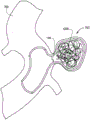
Fig. 12 shows an embodiment of a detachable metal balloon filled with one or more coils or support structures.
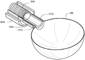
Fig. 13A-B illustrate the manner in which a metal balloon is attached to a delivery device.
Detailed Description
The detachable metal balloon 100 of the present invention as shown in fig. 1A-E is a balloon that is positioned to inflate and expand and remain in an expanded state to occlude a blood vessel and treat many vascular conditions or abnormalities, including aneurysms. A delivery device, such as catheter 300, is used to deliver the balloon 100 to the desired location. The medical device 500 including the catheter and attached balloon as shown in fig. 3-6 may be used as part of a method of occluding a blood vessel or treating a vascular condition or abnormality, such as an aneurysm.
The detachable metal balloon 100 may be comprised of a single continuous layer or wall 102, as shown in fig. 1E. Alternatively, balloon 100 may contain a single continuous wall 102 and additional layers including one or more porous layers 104, as shown in fig. 2A-C. Balloon 100 has an inner surface 106 that defines a space or void 108 when inflated and expanded with a fluid. Balloon 100 has an outer surface 110 that, when expanded, contacts the inner wall of a vessel or vascular structure. A fluid is a substance with particles that easily move and change their relative positions without the need for bulk separation. Fluids that may be used to inflate or expand balloon 100 include liquids, gases, and combinations thereof.
The outer layer 104 may have a plurality of pores 200 that may contain a drug, a pharmacologically active molecule, or a pharmacological composition. Advantageously, balloon 100 may be delivered to a desired location, inflated and expanded, and then detached from a delivery device, such as catheter 300, in the expanded state. The dilation balloon 100 will generally conform to the shape of the lumen in which it is placed, but may also be shaped using external forces, such as physical forces applied by an adjacent dilation angioplasty balloon. In addition, a plurality of detached metal balloons 100 may be utilized to fill the desired voids. Finally, the invention specifically relates to a detachable metal balloon that remains in the lumen or void of a blood vessel or aneurysm in an expanded state.
The metal balloon 100 is attached to a delivery device, such as a catheter 300, and delivered to a desired location. Any delivery member that can be passed through the lumen of a blood vessel, inflated or expanded, and detached from the balloon is generally acceptable. Inflating or expanding the balloon as used herein refers to partially or fully expanding the balloon 100 using a fluid, a solid, or a combination thereof. In various embodiments, sealing the vessel does not require balloon 100 to be fully expanded. For example, the balloon 100 may be partially or fully inflated using a fluid. In another example, balloon 100 may be partially or fully expanded using a solid material alone or in combination with fluid inflation. In all embodiments, the balloon remains in the expanded state after detachment from the delivery device. The expanded state refers to at least partial expansion of the balloon 100, e.g., at least 10%, 20%, or 50% of the maximum balloon volume.
A catheter is a tubular medical device for insertion into a duct, vessel, passageway, or body cavity to allow for the infusion or withdrawal of fluids. Catheters designed for insertion into the lumen of a blood vessel are generally flexible and often constructed of plastic or metal. In some instances, the catheter is placed in the body using a wire or trocar that occupies a lumen defined by the tubular portion of the catheter. Once placed, the wire or trocar may be removed to allow for the infusion or withdrawal of fluids.
The wire is a metal in the form of a thin wire or elongate rod, which is typically very flexible. The basic angiographic guide wire consists of a fixed solid metal core covered by a metal spring coil. The infusion line is a modified guide wire in which the solid metal core is removable, leaving a lumen that can be used to inject or withdraw fluids, such as tissue plasminogen activator solution, proteins that catalyze the breakdown of blood clots. In this way, an infusion wire with a removable core wire may be used as a catheter. Fig. 11A-C show various examples of infusion wires with metal spring coil wires 1100 and removable core wires 1102. Figure 11C shows a partial cross-section of the modified guide wire 1100 with the core wire 1102 removed.
Preferably, the delivery device is a catheter 300 as shown in fig. 3A-C, which can carry the balloon 100 to the desired site. The catheter 300 must also allow the passage of fluids for inflating and expanding the balloon. Catheter 300 is defined as at least one hollow cylindrical member defining a lumen, wherein the catheter is designed and dimensioned such that it can be inserted into the body to deliver balloon 100 to a desired location, inflate or expand the balloon, and detach the balloon therefrom. The conduit 300 will comprise at least one hollow cylindrical member, and more likely two hollow cylindrical members. When the catheter includes two cylindrical members, one cylindrical member may operate with a guiding member, such as a guide wire 302, to guide the device to a desired location. The detachment member may also be used with a catheter, whereby the detachment member is carried on the outer surface or in the wall of one of the cylindrical members or is carried through the lumen of one of the cylindrical members. The second cylindrical member delivers fluid to inflate or expand the balloon 100, and the balloon 100 may be disposed on the outer wall of the cylindrical member(s). An alternative includes a single cylindrical member through which fluid flows to inflate and expand the balloon, and advancing the medical device through a separate catheter in order to guide it to the desired location where it can be inflated, expanded and detached.
The present method includes delivering the balloon 100 to a desired location, and then inflating and expanding the balloon to an expanded state. Once expanded, the delivery device (typically catheter 300) is separated from the balloon 100, which remains expanded. Detachment can be achieved via mechanical separation, for example by shearing the balloon off the delivery catheter tip using another cylindrical member surrounding the catheter or by electrolysis. The dilation balloon 100 fills at least a portion of the lumen of a blood vessel or aneurysm, thereby reducing the risk of subsequent bleeding of the blood vessel or aneurysm. Optionally, outer layer 104 of dilation balloon 100 releases drugs or pharmacologically active molecules to increase thrombus formation on outer surface 110 of balloon 100 and within the lumen of the hemangioma. Optionally, the porous outer layer 104 allows for the growth of adjacent tissue into the metal surface. As part of this method, the delivery device may be positioned using a guide wire 302 that has been placed near the treatment area. In this embodiment, the delivery device is advanced over the guide wire to the appropriate position, and the guide wire 302 is then removed. Alternatively, as part of this method, the balloon 100 may be positioned using the guide catheter 800, wherein a delivery device attached to the balloon as shown in fig. 8A-E is passed through the lumen of the guide catheter and into the lumen of the aneurysm 701, the balloon is inflated or expanded, and then detached from the delivery device.
Balloon
As discussed and shown in fig. 1A-E, balloon 100 has one or more openings 112 and 114 defined by wall 102 or defined by one or more necks 116 and 118. Fluid may enter the opening 112 to expand the space or void 108 defined by the inner surface 106. The inner surface 106 and the outer surface 110 define a balloon wall thickness 120. The balloon 100 is configured to expand and remain expanded after separation from the delivery device.
In various embodiments, one or both of the necks 116 and 118 may extend from the wall 102 or they may extend into the interior space or void 108. Necks 116 and 118 may be used to attach the balloon to the delivery device and may play a role in detaching balloon 100 from the delivery device.
The detachable balloon 100 is formed of a metal that can also take on a variety of forms after expansion. Acceptable shapes include circular, cylindrical, or oblong, as well as shapes defined by aneurysm lumen voids. Embodiments in which balloon 100 has a generally tubular form may be used to treat fusiform aneurysm dilation of a blood vessel. This embodiment may also be used to occlude normal diameter blood vessels for a variety of purposes, including treating bleeding from blood vessels or branches thereof.
In various embodiments, the size of balloon 100 is selected depending on the condition being treated. In a preferred embodiment, the inflated diameter of balloon 100 is in the range of about 2 mm to about 100 mm. Similarly, the preferred inflation volume of the balloon is in the range of about 0.005 cc to about 65 cc. In one embodiment, balloon 100 preferably has an inflated length of between about 2 mm to about 120 mm. Preferably, balloon wall thickness 120 is in a range between about 3 μm and 60 μm, while the diameter of opening 112 is in a range between about 0.1 mm and about 20 mm.
In various embodiments, the wall 102 is solid and the outer layer 104 is in a porous form, as shown in fig. 2A and 2B. The porous or spongy nature of outer layer 104 can be configured to contain a drug, pharmacologically active molecule, or pharmaceutical composition within pores 200. Thus, a drug, pharmacologically active molecule, or pharmaceutical composition can be delivered to a treatment site. A drug, pharmacologically active molecule, or pharmaceutical composition is incorporated into pores 200 of outer layer 104 prior to positioning balloon 100 at a desired location. The drug, pharmacologically active molecule, or pharmaceutical composition is delivered into the well 200 via capillary or capillary action. The diameter of the holes 200 is in the range of about 0.05 μm to about 100 μm. The pore diameter of each balloon may be selected to deliver a particular drug, pharmacologically active molecule, or pharmaceutical composition at a particular rate. By way of example and not limitation, balloon 100 may have a porous outer layer 104 with an average pore diameter of about 0.05 μm to about 5 μm, about 5 μm to about 25 μm, or about 25 μm to about 100 μm.
The drugs, pharmacologically active molecules, or pharmaceutical compositions may be incorporated directly into the pores of the outer layer 104 or they may be incorporated as a solution and/or suspension. By way of example and not limitation, the drug may comprise thrombin, Ethiodol, and Sotradecol ® or combinations thereof. Other drugs, pharmacologically active molecules, or pharmaceutical compositions that promote embolization and coagulation or stimulate growth of adjacent tissue into the porous outer wall of balloon 100 may also be used. Such drugs or pharmacologically active molecules may include molecules for promoting cell or tissue growth such that balloon 100 will physically attach to tissue at the treatment site. The dosage and manner of incorporation of the drug or pharmacologically active molecule into the outer layer 104 is a matter of choice, depending on the treatment being performed.
In various embodiments, the wall 102 and the outer layer 104 are constructed of different biocompatible metals. In other embodiments, the wall 102 and the outer layer 104 are composed of the same metal. Over time, the balloon 100 remains expanded and the balloon is ultimately secured to the surrounding tissue. In another embodiment, as shown in fig. 12, the balloon 100 may be filled with a solid member 1200, such as a metal or polymer coil, a metal or polymer expandable structure, a bead, a sphere, a microsphere, or a combination thereof. Other suitable biocompatible solid materials may also be used.
Alternatively, balloon 100 may include additional padding or layers on the inner surface of wall 1400, as shown in fig. 2C. Additional padding or layers on the inner surface of the wall of balloon 100 may be comprised of polymers, plastics, latex, or rubber, woven or knitted fiber materials, metals, other materials, or combinations thereof. Preferably, the inner layer 1400 is an elastomeric coating bonded to the inner surface 106 of the wall 102. Inner layer 1400 may have a variety of thicknesses preferably in a range between about 0.5 μm and about 59 μm. The total thickness of the outer, inner and wall layers, whether the wall or the walls and both layers are used, will be between about 3 μm and about 60 μm. In a preferred embodiment, inner layer 1400 is a Parylene type, but latex, or other elastomers, may be used. The inner layer 1400 adds mechanical properties (e.g., strength) to the wall 102. Additionally, if the metal portion of the wall contains defects, inner layer 1400 optionally may form a seal that prevents fluid from escaping balloon 100. The balloon wall 102 and any additional layers define an inner surface 106 or 126 such that an interior space or void 108 is defined when the balloon is inflated with a fluid, liquid, gas, or solid.
In another embodiment, the balloon neck 116 or the exterior and/or interior of the balloon may be coated with an insulating substrate, e.g., a polymer such as a Parylene @, while the balloon or a portion of the balloon neck remains uncoated. The uncoated portions may be uncoated portions that are intentionally left out during the coating process, or may be portions that are exposed after coating by laser ablation or other suitable process. After expansion, the uncoated portion of the balloon or balloon neck may be electrically coupled with an electrolysis wire 320 or other insulated conducting wire for conducting electricity, and an electrical current may flow from a power source to the uncoated portion of the balloon or balloon neck to perform electrolysis and dissolve at least a portion of the uncoated portion, thereby separating the expanded balloon 100 from the delivery catheter.
Delivery device
The delivery device may be a single lumen catheter as shown in fig. 4A-C, or a multi-lumen catheter as shown in fig. 3A-C. For example, one potential catheter 300 includes two hollow cylindrical members or tubes that define a lumen, forming a double lumen catheter. One lumen for passage of a guiding member, such as guide wire 302, and a second lumen for passage of fluid or gas into the balloon for inflation and expansion of balloon 100. Given the generally circular form of the metal balloon, this embodiment may be used to treat focal (focal), eccentric, circular, and saccular aneurysm dilatation of a blood vessel, or an aneurysm. Catheter 300 may be configured to be passed through the vascular system, for example, with balloon 100 in a compressed form. The catheter 300 includes a detachment member, such as an electrolysis wire 320 shown in fig. 3C, for separating the catheter from the balloon, such that the dilation balloon 100 remains in place when the catheter is removed from the body.
In one embodiment, the wall thickness of the hollow cylindrical member is in the range of about 0.05 mm to about 0.5 mm. Preferably, the cylinder wall thickness is in the range of about 0.05 mm to about 0.15 mm. The diameter of the lumen defined by the cylindrical member is in the range of about 0.15 mm to about 2.2 mm. In a preferred embodiment, the lumen diameter is in the range of about between 0.7 mm to about 1.57 mm. In one embodiment, catheter 300 is configured with balloon 100 attached to the outer surface of the catheter in a deflated, compressed, and/or pleated form. Catheter 300 is advanced over guide wire 302 until compression balloon 100 reaches the desired location, at which point the balloon is expanded and separated from the catheter. In another embodiment, balloon 100 is attached to catheter 300 in a deflated, compressed, and/or crimped form. The catheter 300 is configured to pass completely through the lumen of the larger guide catheter until the compression balloon 100 reaches the desired location, at which point the balloon is expanded and separated from the catheter.
The catheter 300 is constructed of a biocompatible material. By way of example and not limitation, the catheter 300 and its various components may be constructed of silicone rubber, natural rubber, polyvinyl chloride, polyurethane, copolyester polymer, thermoplastic rubber, silicone-polycarbonate copolymer, polyethylene-ethyl vinyl acetate copolymer, woven polyester fibers, or combinations thereof. In one embodiment, the walls of the hollow cylindrical member may be reinforced with a metal, such as braided stainless steel or nitinol (nitinol), to enhance control and reduce kinking of the catheter 300 during use.
By way of example and not limitation, the guide member may be a separate flexible guide wire 302 as shown in fig. 3, 5 and 7. The guide wire 302 is preferably a straight, soft-tipped angiographic wire having a length sufficient to allow the distal end of the guide wire to reach the desired location, while the proximal end extends out of and away from the entry point into the vascular system. In one embodiment, the guide wire 302 has a curved J-shaped distal tip, typically constructed of a memory alloy or braided metal that causes the tip to return to the J-shape after any applied stress is removed.
Fig. 3A shows a longitudinal view of an embodiment of a catheter portion of a detachable metal balloon medical device. Fig. 3B-C show longitudinal views of embodiments of a detachable metal balloon medical device 500. Catheter 300 is moved over guide wire 302 to deliver balloon 100, deliver fluid to inflate and expand the balloon, and then detach the balloon therefrom. The catheter 400 may include a single hollow cylindrical member or tube defining a lumen (as shown in fig. 4, 6, and 8) or a plurality of hollow cylindrical members defining a number of lumens (as shown in fig. 3, 5, and 7). As shown, a suitable configuration for the embodiment of the conduit 300 includes a first hollow cylindrical member 304 and a hollow cylindrical member 306 that are adjacent and parallel to each other. The hollow cylindrical members 304 and 306 define two lumens. One lumen 326, the fluid or gas delivery lumen, provides fluid or gas for inflating and expanding the balloon. Another lumen 324, the guide member lumen, receives a guide wire 302 for assisting in positioning the balloon 100 at a desired location. In one embodiment, hollow cylindrical members 304 and 306 may be seated in a third hollow cylindrical member (not shown). In other embodiments, the first hollow cylindrical member 304 may be disposed inside the second hollow cylindrical member 306, or the hollow cylindrical members may be coaxial.
The proximal end of the first hollow cylindrical member 306 includes a balloon inflation or dilation port 308. The balloon inflation or dilation port 308 enables the hollow cylindrical member 306 to communicate with a pressurized fluid or gas source, such as a syringe 314 or pump (not shown) containing, for example, water, saline, or a radiopaque solution.
The potential fluid provided by the pressurized fluid source comprises a liquid, a gas, or a combination thereof. By way of example and not limitation, the fluid may be water, saline solution, radiographic contrast solution, or a mixture or any of the three. In one embodiment, the fluid may further comprise a solution or suspension of a drug or pharmacologically active molecule for inducing tissue growth and/or embolization at the balloon inflation location. In another embodiment, a plurality of solids, such as wires, coils, support structures, or acrylic gelatin microspheres, are suspended in the fluid, which help to inflate or expand the balloon 100 and maintain the expanded shape of the balloon 100.
The proximal end of the hollow cylindrical member 304 includes a guidewire port 310. The guide wire port 310 allows for easy insertion of the guide wire 302 into the hollow cylindrical member 304. A guide wire 302 is fed through a hollow cylindrical member 304 and extends out of the distal end of the catheter 300. In this embodiment, catheter 300 is advanced over guide wire 302 and positioned in a selected section of a blood vessel or into the lumen of a vascular aneurysm. Once the catheter 300 is in the desired position, the removable wire 404 is withdrawn from the delivery device, inflating or expanding the balloon 100 with fluid provided into the hollow cylindrical member 306 via the syringe 314 connected to the balloon inflation port 308. With the guide wire 302 removed, the guide wire port 310 and hollow cylindrical member 304 may be used to infuse a fluid such as saline, a radiographic contrast agent, or a solution of a drug such as thrombin, or may be used to aspirate fluid or blood.
The size of the catheter 300 is a matter of design choice, depending on the size of the particular vessel or lumen in which it is used. For example, the medical device 500 may be used to occlude very small vessels or biological conduits, such as in the brain, where the diameter of the device prior to inflation or expansion may be about 2-5 Fr. In another example, the medical device 500 may be used to occlude larger blood vessels, such as varicose veins. In this example, the diameter of the catheter may be about 2-10 Fr. In various embodiments, the catheter 300 can be sized to occlude a non-vascular biological conduit or abnormal communication between biological spaces such as an enterocutaneous fistula. The length of the catheter 300 is also a matter of design choice, depending on the distance between the point of entry into the body and the location to be treated. For example, and without limitation, the catheter length may be in a range between about 5 cm and about 300 cm.
In one embodiment, balloon 100 has one or more openings, such as opening 112, attached to the distal end of hollow cylindrical member 306. Alternatively, balloon 100 may have two openings, with first opening 112 attached to the distal ends of hollow cylindrical members 306 and 304 and second opening 114 attached to the distal end of hollow cylindrical member 304. In this embodiment, hollow cylindrical member 304 extends through the interior of balloon 100. Balloon 100 may be folded, compressed, and/or wrapped around the exterior of the distal end of catheter 300, as shown in fig. 3B.
This embodiment of the catheter 300 also includes a detachment member, such as an electrolysis wire 320 or an insulated wire, extending along the length of the delivery device. The detachment member is used to separate the balloon 100 from the catheter 300. In one embodiment, the electrolysis wire 320 is laid along the outer surface of the hollow cylindrical member 304, as shown in fig. 3C, 5, and 9B.
In various embodiments, the electrolysis wire 320 or insulated conducting wire is an elongated wire that can conduct electrical current, and can be disposed within the lumen of the cylindrical member, disposed within the wall of the cylindrical member, or attached to the exterior of the cylindrical member.
The electrolysis wire 320 is in electrical communication with a weld or solder joint 316 between the balloon 100 and the delivery device. In this embodiment, a direct current or charge (DC current) is applied to the electrolysis wire 320 after the balloon 100 is inflated. The DC current dissolves at least a portion of the weld or weld joint 316, causing the expanded balloon to separate from the delivery device and leaving the expanded balloon 100 in the desired position when the delivery device is removed. In another embodiment, the electrolysis wire 320 is in electrical communication with the balloon 100 itself, which is attached to the delivery device by adhesive or other attachment method. In this embodiment, a direct current or charge (DC current) is applied to balloon 100 after balloon 100 is inflated. The DC current dissolves at least a portion of the balloon 100, causing the remaining portion of the expanded balloon to separate from the delivery device and leaving the expanded balloon 100 in the desired location when the delivery device is removed.
In one embodiment, the opening of the inflatable balloon 100 is open after detachment from the catheter 300. In other embodiments, the opening of the inflatable balloon 100 is closed before, during, or after detachment from the catheter 300. By way of example and not limitation, the opening may be closed by application of an external force, such as with an adjacent angiographic or shaping balloon. In all embodiments, balloon 100 retains its expanded shape after detachment and is resistant to compression. The balloon 100 remains inflated even though the rigidity of the balloon wall is such that the internal and external pressures of the inflated balloon are equal or similar. In another example, balloon dilation is assisted by infusion of a rigid or semi-rigid material into balloon 100.
In still other embodiments, balloon 100 is not welded to catheter 300, but is temporarily secured to the catheter, such as by crimping. In these embodiments, balloon 100 is detached from catheter 300 by friction and/or via a catheter or various tools inserted around the catheter.
In other embodiments, balloon 100 is not welded to catheter 300, but is secured to the catheter with an adhesive. In these embodiments, balloon 100 is detached from catheter 300 by friction, electrolysis, and/or various tools inserted through or around the catheter.
Fig. 4A shows a longitudinal view of an embodiment of a catheter portion of a detachable metal balloon medical device. Fig. 4B-C show longitudinal views of embodiments of a detachable metal balloon medical device 500. This embodiment includes a single lumen catheter 400 having a single hollow cylindrical member 306 for receiving a removable wire 404. The walls of the conduit may be constructed of a plastic or polymer material as described previously. In another embodiment, the wall of the catheter is constructed from a coiled metal coil. In this embodiment, the combined hollow cylindrical member 306 and removable wire 404 are similar to existing infusion wires. The hollow cylindrical member 306 includes a connection port 308 at a proximal end and is attached to the balloon 100 at a distal end, for example, using a weld, adhesive, or crimping. As shown in fig. 4B, balloon 100 may be wrapped, compressed, and or folded along the exterior of hollow cylindrical member 306.
In one embodiment, the catheter 400 with the compression balloon 100 is advanced to a desired location through the lumen of a larger guide catheter as shown in fig. 8A-E. The compression balloon 100 is advanced beyond the distal end of the larger guide catheter and into the desired location. Once catheter 400 has been placed at the desired location, wire 404 is removed from hollow cylindrical member 306 and a fluid source, such as syringe 314, is connected to connection port 308 to inflate or expand balloon 100. The removable wire 404 may include a handle 408 or other device to facilitate insertion and removal. After balloon 100 is expanded, as shown in fig. 4C, catheter 400 may be separated from balloon 100 so that catheter 400 may be removed while leaving the expanded balloon 100 in the desired location. In one embodiment, after balloon 100 is inflated or expanded, a DC current is applied to electrolysis wire 320 to dissolve the weld or solder between the balloon and catheter 400. Once the weld has dissolved, the catheter 400 is removed while the expanded balloon 100 remains in place. In another embodiment, a DC current is applied to electrolysis wire 320 to dissolve a portion of the balloon. Once portions of the balloon are dissolved, the catheter 400 is removed while leaving the remainder of the expanded balloon 100 in place.
Fig. 5 and 6 illustrate additional embodiments of detachable balloon delivery devices attached to the balloon 100 in a deflated configuration. In one embodiment, balloon 100 is folded into folds, and the folds of the folded balloon are then wrapped around catheter 300 and the balloon is compressed against catheter 300. In another embodiment, balloon 100 is folded into folds, the folds of the folded balloon are then wrapped around removable wire 404, and the balloon is then compressed against removable wire 404.
In various embodiments, balloon 100 is attached to catheter 300, 400, then pleats 502 are formed, then the pleats are wrapped and compressed onto catheter or removable wire 404. In another embodiment, balloon 100 is folded to form folds 502, then attached to catheter 300, 400, and then folded or compressed onto the outer surface of catheter 300, 400, or removable wire 404.
Method
The present method includes many steps of delivering the balloon 100 to a desired location, inflating and expanding the balloon 100, and separating the balloon from the delivery device. In one embodiment, the method includes the steps of accessing the artery with a needle, and then advancing a guide wire, such as guide wire 302, through the needle. The needle is then removed and optionally a vascular sheath is inserted. The guide wire 302 is then further advanced to the desired position. Optionally, a standard angiographic catheter is used with the guide wire 302 to advance the guide wire to the desired location. After the guide wire 302 is properly placed, the standard angiographic catheter is removed from the body. The catheter 300 with the balloon 300 distally is then advanced over the guide wire 302 until the catheter is positioned at the desired location. Optionally, guide wire 302 is then withdrawn and balloon 100 is inflated and expanded with pressurized fluid. The expanded balloon 100 is detached from the catheter 300 and the catheter is removed with the guide wire 302. As described above, the method may further include the step of providing an electrical current to the electrolysis wire 320 to dissolve the weld or solder 316 attaching the balloon 100 to the catheter, or to dissolve a portion of the balloon itself. In one embodiment, the method further comprises the step of shaping the expanded balloon 100. Shaping balloon 100 may be accomplished by applying external and/or internal forces, for example, with an adjacent angioplasty balloon or a closed balloon.
Fig. 7A-E and 8A-E illustrate the sequence of positioning the balloon 100 in the aneurysm cavity of a blood vessel, expanding the balloon, and detaching. In fig. 7A-E, balloon 100 is filled in an aneurysm 703 of a blood vessel 702. Balloon 100 is inflated with a pressurized liquid, gas, or combination thereof. In one embodiment, the fluid contains a suspension of coils, beads, and/or a solution or suspension of a drug, a pharmacologically active molecule, or a pharmaceutical composition.
The expanded shape of balloon 100 is based on the abnormality being treated. In one example, balloon 100 is shaped both by the shape of the aneurysm lumen or void, and optionally by the application of external forces. The external force may be applied by inflating a separate adjacent balloon (not shown) in the lumen of the vessel 702, pushing the wall of the balloon 100 toward the aneurysm. In other embodiments, balloon 100 is manufactured in an aspheric orientation to match the contour of the lumen of a particular aneurysm 703. Other shapes and orientations may be used. The outer surface 110 of the balloon 100 is in contact with a majority of the inner surface 700 of the aneurysm 703. In one embodiment, the outer surface 110 of the balloon 100 is in contact with at least 50% of the inner surface 700 of the aneurysm 703. In other embodiments, the outer surface 110 is in contact with more than 90% of the inner surface 700. The dilation balloon fills a majority of the lumen of the aneurysm 701. In one embodiment, the dilation balloon fills at least 50% of the lumen of the aneurysm 701.
In fig. 7E, catheter 300 and guide wire 302 have been withdrawn and opening 112 of balloon 100 is still open. In other embodiments, the opening 112 of the balloon may be closed. In all embodiments, balloon 100 will remain expanded.
In another embodiment shown in fig. 8A-E, a guide catheter 800 is used to access the lumen 701 of an aneurysm 703. A single lumen catheter, such as catheter 400, is then advanced through the guide catheter 800. Catheter 400 communicates with opening 112 of balloon 100. Pressurized fluid is transferred through the catheter 400 into the interior space or void 108 of the balloon so that its shape closely matches the contour of the aneurysm 800 when the balloon 100 is expanded. In one embodiment, balloon 100 is manufactured into a particular shape prior to attachment to catheter 400.
In all embodiments, the expanded shape of balloon 100 is determined by four factors: 1) the manufactured shape of balloon 100; 2) the degree of inflation or dilation; 3) the size and shape of the aneurysm 703; and 4) the effect of any external forces applied after inflation or expansion. By way of example and not limitation, the manufactured size and shape of balloon 100 may be determined by measuring aneurysm 703. The measurement may be made by using the medical image and a standard distance reference marker. Other methods of measuring aneurysms may also be used.
In another embodiment, the balloon 100 may be manipulated and deployed in vivo or even in situ within the aneurysm 703. In this embodiment, it is not necessary to determine the precise contour of the aneurysm 703 prior to insertion of the balloon 100. Balloon 100 is shaped by applying internal and/or external forces. For example, the external force may be applied by using an external angioplasty balloon, or by a tool inserted through or around the catheter 400. In other embodiments, balloon 100 may be shaped in a step that is either before or after the step of disengaging the balloon from catheter 400.
In other embodiments, two or more balloons similar to balloon 100 may be positioned and inflated to fill a lumen of a particular segment of a blood vessel, aneurysm lumen or void, or part or all of another body lumen. In these embodiments, a pre-shaped balloon, an unformed balloon, a malleable balloon, or a combination thereof may be used. In all embodiments, the balloons are positioned so as to maintain their expanded shape and resist accidental compression or deformation.
Fig. 9A shows an axial cross-sectional view of a double lumen catheter 300. The hollow cylindrical member 304 has an outer wall 900 and an inner wall 902, and the hollow cylindrical member 306 has an outer wall 904 and an inner wall 906. The cylindrical members 304 and 306 are parallel and adjacent to each other, while the electrolysis wire 320 extends along the outer wall 904 of the hollow cylindrical member 306. Fig. 9B is an alternative to the device in fig. 9A, where fig. 9B shows an axial cross-sectional view of an alternative dual lumen catheter 300. In one embodiment, hollow cylindrical member 304 is disposed within the lumen of second cylindrical member 306. In this embodiment, the electrolysis wire 302 extends along the outer wall 904 of the hollow cylindrical member 306.
In another embodiment shown in fig. 9C, an electrolysis wire 320 extends within a lumen 326 for inflating or dilating the balloon. In another embodiment shown in fig. 9D, electrolysis wire 320 is disposed within the wall of conduit 300.
Fig. 9E shows an axial cross-sectional view of the dual lumen catheter 300 attached to the balloon 100. Balloons 100 and 326 are in fluid communication and are detached with electrolysis wire 320 extending through the wall of catheter 300.
Fig. 10A is an axial cross-sectional view of a single lumen catheter 400. As shown, the electrolysis wire 320 extends along the outer wall 1000 of the hollow cylindrical member 306. In another embodiment shown in fig. 10B, the electrolysis wire 320 extends within the wall of the cylindrical member 306. Fig. 10C shows an axial cross-sectional view of the single lumen catheter 400 attached to the balloon 100. The balloon 100 is initially welded, or glued to the outer wall 1000 of the hollow cylindrical member 306 and detached with electrolysis wires 320 extending along the outer wall.
The balloon 100 may also be joined to the delivery device by a frictional engagement, wherein the opening or neck of the balloon mates with the distal end of the delivery device to fit together, but there is no joint (e.g., a joint with adhesive or solder) between the balloon and the delivery device. Instead, the inflated balloon 100 and the delivery device may simply be pulled apart. The balloon 100 is detached from the delivery catheter by pulling the delivery catheter away from the balloon or by pushing the balloon away from the delivery catheter. Fig. 13A-B illustrate an embodiment of a medical device 500 in which the balloon 100 is attached to a delivery device using a friction fit. As shown in fig. 13A, the neck 1714 of the balloon 100 is frictionally engaged on the exterior of the distal end 1712 of the delivery device 306. For this embodiment, the medical device 500 is passed through the guide catheter 800 with the compression balloon, and the removable wire is then withdrawn from the delivery device and the balloon 100 is inflated. In this embodiment, the guide catheter 800 may then be advanced until the wall of the inflatable balloon 100 is inflated, and then the delivery device may be retracted or the guide catheter 800 may be pushed forward, thereby disengaging the inflatable balloon. As shown in fig. 13B, the elastic sleeve or wrap 1724 can be bonded to the delivery device 306 and can then frictionally engage the exterior of the neck 1714 of the balloon 100 while the distal end of the delivery device 1712 simultaneously frictionally engages the interior surface of the neck 1714 of the balloon 100.
For the balloon, wherein the balloon outer surface comprises a plurality of straight or branched protrusions made of nitinol or fibers.
For the balloon, wherein the length of the protruding portion is in a range of 0.01 μm to about 57 μm.
It should be understood that the apparatus and methods of the present invention are capable of being incorporated in the form of a variety of embodiments, only some of which have been illustrated and described above. The present invention may be embodied in other specific forms without departing from its spirit or essential characteristics. The described embodiments are to be considered in all respects only as illustrative and not restrictive, and the scope of the invention is, therefore, indicated by the appended claims rather than by the foregoing description. All changes which come within the meaning and range of equivalency of the claims are to be embraced within their scope.
Claims (33)
1. A medical device, comprising:
a unileaflet expandable metal balloon having a wall with an inner surface defining a void of the balloon, an outer surface, and an opening in the wall that allows fluid to pass into the void of the balloon, the opening defined by a neck, wherein the neck remains open after the balloon is expanded by the fluid from a compressed configuration to an expanded configuration, and
a delivery device joined to the metal balloon by frictional engagement, wherein an inner surface of the neck is frictionally engaged to an outer surface of a distal end of the delivery device, and
wherein the metal balloon and the neck remain open after separation from the delivery device, the metal balloon retaining its expanded shape and being resistant to compression, and wherein the metal balloon remains expanded due to the rigidity of the metal balloon's walls even if the pressure inside and outside the expanded metal balloon is equal.
2. The medical device of claim 1, wherein the metal balloon is coupled to the distal end of the delivery device with a friction fit through an elastic sleeve or wrap.
3. The medical device of claim 1, wherein the metal balloon has a compressed diameter in a range of 0.65 mm to 2.25 mm when the metal balloon is in the compressed configuration.
4. The medical device of claim 1, wherein the metal balloon has an expanded diameter in a range of 2 mm to 100 mm when the metal balloon is in the expanded configuration.
5. The medical device of claim 1, wherein the metal balloon has an expanded length in a range between 2 mm to 120 mm when the metal balloon is in the expanded configuration.
6. The medical device of claim 1, wherein the wall of the metal balloon is made of a metal selected from the group consisting of: gold, platinum, silver, alloys thereof, and combinations thereof.
7. The medical device of claim 1, wherein a wall thickness of the metal balloon is in a range between 3 μ ι η and 60 μ ι η.
8. The medical device of claim 1, wherein the metal balloon is folded to form one or more pleats prior to compression.
9. The medical device of claim 1, wherein the metal balloon is attached to the delivery device by an adhesive substance.
10. The medical device of claim 9, wherein the outer surface of the wall of the metal balloon is coated with an insulating substance.
11. The medical device of claim 9, wherein the inner and outer surfaces of the wall of the metal balloon are coated with an insulating substance.
12. The medical device of claim 10 or 11, wherein at least a portion of the metal balloon is uninsulated.
13. The medical device of claim 10 or 11, wherein the insulating substance comprises a Parylene ™ polypeptide.
14. The medical device according to claim 1, wherein the neck has a wall thickness in a range between 3 μ ι η and 60 μ ι η.
15. The medical device of claim 1, wherein the neck has a length between 0.5 mm and 60 mm.
16. The medical device of claim 1, wherein the neck extends into the void of the balloon.
17. The medical device of claim 1, wherein the metal balloon further comprises an outer porous layer on the outer surface.
18. The medical device of claim 17, wherein the outer porous layer of the metal balloon is fabricated from a metal selected from the group consisting of: gold, platinum, silver, alloys thereof, and combinations thereof.
19. The medical device of claim 17, wherein the outer porous layer has a plurality of pores having a diameter in a range of 0.05 μ ι η to 100 μ ι η.
20. The medical device of claim 19, wherein the plurality of pores in the outer porous layer contain a drug or a pharmacologically active molecule.
21. The medical device of claim 19, wherein the plurality of pores in the outer porous layer contain a pharmaceutical composition.
22. The medical device of claim 19, wherein the plurality of pores in the outer porous layer contain a substance selected from the group consisting of: thrombin, Ethiodol, Sotradecol, platelet derived growth factors and combinations thereof.
23. The medical device of claim 1, wherein the wall of the metal balloon includes an inner layer disposed on the inner surface.
24. The medical device of claim 23, wherein the material used to form the inner layer is selected from the group consisting of: polymers, elastomers, and combinations thereof.
25. The medical device of claim 23, wherein the material used to form the inner layer is latex.
26. The medical device of claim 23, wherein the inner layer is comprised of Parylene ™.
27. The medical device of claim 1, wherein the metal balloon is at least partially filled with a solid.
28. The medical device of claim 27, wherein the solid body comprises a support structure.
29. The medical device of claim 28, wherein the support structure is selected from the group consisting of: a coil or wire of metal or polymer, an expandable structure of metal or polymer, a bead, a sphere, or a combination thereof.
30. The medical device of claim 29, wherein the support structure is selected from microspheres.
31. The medical device of claim 1, further comprising:
a second inflation balloon disposed adjacent to the metal balloon, whereby the second inflation balloon occupies a remaining portion of the space in which the metal balloon is disposed.
32. The medical device of claim 31, further comprising:
a third inflation balloon disposed adjacent to the metal balloon and the second inflation balloon, whereby the third inflation balloon occupies a remaining portion of the space in which the metal balloon and the second inflation balloon are disposed.
33. The medical device of any one of claims 1-11, wherein the fluid is a gas.
Applications Claiming Priority (3)
| Application Number | Priority Date | Filing Date | Title |
|---|---|---|---|
| US201161433305P | 2011-01-17 | 2011-01-17 | |
| US61/433305 | 2011-01-17 | ||
| CN201280005574.7A CN103391797B (en) | 2011-01-17 | 2012-01-17 | Detachable metal balloon delivery device and method |
Related Parent Applications (1)
| Application Number | Title | Priority Date | Filing Date |
|---|---|---|---|
| CN201280005574.7A Division CN103391797B (en) | 2011-01-17 | 2012-01-17 | Detachable metal balloon delivery device and method |
Publications (2)
| Publication Number | Publication Date |
|---|---|
| CN107320146A CN107320146A (en) | 2017-11-07 |
| CN107320146B true CN107320146B (en) | 2022-03-01 |
Family
ID=46516296
Family Applications (6)
| Application Number | Title | Priority Date | Filing Date |
|---|---|---|---|
| CN201710994867.7A Active CN107811668B (en) | 2011-01-17 | 2012-01-17 | Blockstent devices and methods of use |
| CN201710270208.9A Active CN107320146B (en) | 2011-01-17 | 2012-01-17 | Detachable metal balloon delivery device and method |
| CN201910501355.1A Pending CN110464402A (en) | 2011-01-17 | 2012-01-17 | Medical external member and the method for forming balloon-stent |
| CN201280005586.XA Active CN103476349B (en) | 2011-01-17 | 2012-01-17 | Balloon-stent device and application method |
| CN201280005574.7A Active CN103391797B (en) | 2011-01-17 | 2012-01-17 | Detachable metal balloon delivery device and method |
| CN201280008971.XA Active CN103747750B (en) | 2011-01-17 | 2012-01-17 | Block holder device and application method |
Family Applications Before (1)
| Application Number | Title | Priority Date | Filing Date |
|---|---|---|---|
| CN201710994867.7A Active CN107811668B (en) | 2011-01-17 | 2012-01-17 | Blockstent devices and methods of use |
Family Applications After (4)
| Application Number | Title | Priority Date | Filing Date |
|---|---|---|---|
| CN201910501355.1A Pending CN110464402A (en) | 2011-01-17 | 2012-01-17 | Medical external member and the method for forming balloon-stent |
| CN201280005586.XA Active CN103476349B (en) | 2011-01-17 | 2012-01-17 | Balloon-stent device and application method |
| CN201280005574.7A Active CN103391797B (en) | 2011-01-17 | 2012-01-17 | Detachable metal balloon delivery device and method |
| CN201280008971.XA Active CN103747750B (en) | 2011-01-17 | 2012-01-17 | Block holder device and application method |
Country Status (13)
| Country | Link |
|---|---|
| US (9) | US9572697B2 (en) |
| EP (5) | EP2665508B1 (en) |
| JP (8) | JP6546718B2 (en) |
| KR (7) | KR102137221B1 (en) |
| CN (6) | CN107811668B (en) |
| AU (8) | AU2012207386A1 (en) |
| BR (3) | BR112013018117B1 (en) |
| CA (3) | CA2824284C (en) |
| ES (4) | ES2711325T3 (en) |
| HK (1) | HK1246131A1 (en) |
| IL (6) | IL227440B (en) |
| RU (6) | RU2666397C2 (en) |
| WO (3) | WO2012099910A2 (en) |
Families Citing this family (125)
| Publication number | Priority date | Publication date | Assignee | Title |
|---|---|---|---|---|
| US8425549B2 (en) | 2002-07-23 | 2013-04-23 | Reverse Medical Corporation | Systems and methods for removing obstructive matter from body lumens and treating vascular defects |
| EP1750619B1 (en) | 2004-05-25 | 2013-07-24 | Covidien LP | Flexible vascular occluding device |
| CA2758946C (en) | 2004-05-25 | 2014-10-21 | Tyco Healthcare Group Lp | Vascular stenting for aneurysms |
| US9675476B2 (en) | 2004-05-25 | 2017-06-13 | Covidien Lp | Vascular stenting for aneurysms |
| US8152833B2 (en) | 2006-02-22 | 2012-04-10 | Tyco Healthcare Group Lp | Embolic protection systems having radiopaque filter mesh |
| EP2460478B1 (en) | 2008-04-21 | 2021-09-08 | Covidien LP | Braid-ball embolic devices and delivery systems |
| US11464518B2 (en) | 2008-05-01 | 2022-10-11 | Aneuclose Llc | Proximal concave neck bridge with central lumen and distal net for occluding cerebral aneurysms |
| US11471164B2 (en) | 2008-05-01 | 2022-10-18 | Aneuclose Llc | Methods of occluding a cerebral aneurysm by inserting embolic members or material into an intrasacular implant |
| US11484322B2 (en) | 2018-01-03 | 2022-11-01 | Aneuclose Llc | Aneurysm neck bridge with a closeable opening or lumen through which embolic material is inserted into the aneurysm sac |
| US10716573B2 (en) | 2008-05-01 | 2020-07-21 | Aneuclose | Janjua aneurysm net with a resilient neck-bridging portion for occluding a cerebral aneurysm |
| US11583289B2 (en) | 2008-05-01 | 2023-02-21 | Aneuclose Llc | Aneurysm-occluding mesh ribbon with a series of loops or segments having distal-to-proximal variation in size, shape, and/or orientation |
| US11357511B2 (en) | 2008-05-01 | 2022-06-14 | Aneuclose Llc | Intrasacular aneurysm occlusion device with globular first configuration and bowl-shaped second configuration |
| US10028747B2 (en) | 2008-05-01 | 2018-07-24 | Aneuclose Llc | Coils with a series of proximally-and-distally-connected loops for occluding a cerebral aneurysm |
| US9675482B2 (en) | 2008-05-13 | 2017-06-13 | Covidien Lp | Braid implant delivery systems |
| US8409269B2 (en) | 2009-12-21 | 2013-04-02 | Covidien Lp | Procedures for vascular occlusion |
| US9358140B1 (en) | 2009-11-18 | 2016-06-07 | Aneuclose Llc | Stent with outer member to embolize an aneurysm |
| US8998947B2 (en) | 2010-09-10 | 2015-04-07 | Medina Medical, Inc. | Devices and methods for the treatment of vascular defects |
| US8974512B2 (en) | 2010-09-10 | 2015-03-10 | Medina Medical, Inc. | Devices and methods for the treatment of vascular defects |
| WO2012078678A1 (en) | 2010-12-06 | 2012-06-14 | Tyco Healthcare Group Lp | Vascular remodeling device |
| JP6546718B2 (en) | 2011-01-17 | 2019-07-17 | メタクティブ・メディカル・インコーポレイテッドMetactive Medical, Inc. | Block stent device and method of use |
| US11484318B2 (en) | 2011-01-17 | 2022-11-01 | Artio Medical, Inc. | Expandable body device and method of use |
| US9089332B2 (en) | 2011-03-25 | 2015-07-28 | Covidien Lp | Vascular remodeling device |
| AU2012253583B2 (en) | 2011-05-11 | 2014-09-25 | Covidien Lp | Vascular remodeling device |
| WO2013049448A1 (en) | 2011-09-29 | 2013-04-04 | Covidien Lp | Vascular remodeling device |
| US9072620B2 (en) | 2011-11-04 | 2015-07-07 | Covidien Lp | Protuberant aneurysm bridging device deployment method |
| JP6356612B2 (en) | 2012-01-17 | 2018-07-11 | メタクティブ・メディカル・インコーポレイテッドMetactive Medical, Inc. | Expandable device and usage |
| US9011480B2 (en) | 2012-01-20 | 2015-04-21 | Covidien Lp | Aneurysm treatment coils |
| US10182932B2 (en) | 2012-02-21 | 2019-01-22 | Allurion Technologies, Inc. | Methods and devices for deploying and releasing a temporary implant within the body |
| US9452070B2 (en) | 2012-10-31 | 2016-09-27 | Covidien Lp | Methods and systems for increasing a density of a region of a vascular device |
| CN108354645A (en) | 2012-11-13 | 2018-08-03 | 柯惠有限合伙公司 | plugging device |
| US20140142620A1 (en) * | 2012-11-19 | 2014-05-22 | Cook Medical Technologies Llc | Degradable balloon device and method for closure of openings in a tissue wall |
| TWI654962B (en) * | 2013-03-15 | 2019-04-01 | 美商麥塔克提夫醫療公司 | medical system |
| WO2014145012A2 (en) | 2013-03-15 | 2014-09-18 | Covidien Lp | Delivery and detachment mechanisms for vascular implants |
| EP2967571B1 (en) | 2013-03-15 | 2022-08-31 | Covidien LP | Occlusive device |
| WO2015073704A1 (en) | 2013-11-13 | 2015-05-21 | Covidien Lp | Galvanically assisted attachment of medical devices to thrombus |
| US9987014B2 (en) | 2014-02-06 | 2018-06-05 | Boston Scientific Scimed, Inc. | Occlusion device |
| US11076860B2 (en) | 2014-03-31 | 2021-08-03 | DePuy Synthes Products, Inc. | Aneurysm occlusion device |
| US11154302B2 (en) | 2014-03-31 | 2021-10-26 | DePuy Synthes Products, Inc. | Aneurysm occlusion device |
| US9713475B2 (en) | 2014-04-18 | 2017-07-25 | Covidien Lp | Embolic medical devices |
| EP3970635A1 (en) | 2014-04-30 | 2022-03-23 | Cerus Endovascular Limited | Occlusion device |
| US20150330158A1 (en) * | 2014-05-19 | 2015-11-19 | Crescent Point Energy Corp. | Apparatuses, systems, and methods for injecting fluids into a subterranean formation |
| CN105213076A (en) * | 2014-06-12 | 2016-01-06 | 微创心脉医疗科技(上海)有限公司 | A kind of artificial tumor neck and preparation method thereof |
| US8900304B1 (en) | 2014-06-17 | 2014-12-02 | Abdulrazzaq Alobaid | Kyphoplasty cement encapsulation balloon |
| US9579427B2 (en) | 2014-06-28 | 2017-02-28 | Cordis Corporation | Thin-film composite retrievable endovascular devices and method of use |
| US9918718B2 (en) * | 2014-08-08 | 2018-03-20 | DePuy Synthes Products, Inc. | Embolic coil delivery system with retractable mechanical release mechanism |
| US9814466B2 (en) | 2014-08-08 | 2017-11-14 | Covidien Lp | Electrolytic and mechanical detachment for implant delivery systems |
| RU2721288C2 (en) * | 2014-09-17 | 2020-05-18 | Метэктив Медикал, Инк. | Medical device for saccular aneurysm treatment |
| CN107249517B (en) * | 2014-12-31 | 2022-01-28 | 安德乐吉克斯有限责任公司 | Dual inflatable arterial prosthesis |
| US10478194B2 (en) | 2015-09-23 | 2019-11-19 | Covidien Lp | Occlusive devices |
| US10314593B2 (en) | 2015-09-23 | 2019-06-11 | Covidien Lp | Occlusive devices |
| CN106618660A (en) * | 2015-10-29 | 2017-05-10 | 西安东澳生物科技有限公司 | Self-crawling blood vessel blocking device |
| US10080875B2 (en) * | 2015-12-01 | 2018-09-25 | Medtronic Vascular, Inc. | Handle component for providing a pressurized material |
| EP3386402B1 (en) | 2015-12-07 | 2022-02-23 | Cerus Endovascular Limited | Occlusion device |
| CN108738305A (en) * | 2016-01-22 | 2018-11-02 | 韦恩堡金属研究产品公司 | Woven or woven tubular metal structure |
| US10729447B2 (en) | 2016-02-10 | 2020-08-04 | Microvention, Inc. | Devices for vascular occlusion |
| EP3426181B1 (en) | 2016-03-11 | 2020-10-21 | Cerus Endovascular Limited | Occlusion device |
| US10893869B2 (en) | 2016-03-24 | 2021-01-19 | Covidien Lp | Thin wall constructions for vascular flow diversion |
| CN105854161B (en) * | 2016-06-21 | 2022-06-24 | 中国福利会国际和平妇幼保健院 | Cervical anti-adhesion dilating rod and preparation method and application thereof |
| US10828039B2 (en) | 2016-06-27 | 2020-11-10 | Covidien Lp | Electrolytic detachment for implantable devices |
| US10828037B2 (en) | 2016-06-27 | 2020-11-10 | Covidien Lp | Electrolytic detachment with fluid electrical connection |
| US11051822B2 (en) | 2016-06-28 | 2021-07-06 | Covidien Lp | Implant detachment with thermal activation |
| US10478195B2 (en) | 2016-08-04 | 2019-11-19 | Covidien Lp | Devices, systems, and methods for the treatment of vascular defects |
| US10576099B2 (en) | 2016-10-21 | 2020-03-03 | Covidien Lp | Injectable scaffold for treatment of intracranial aneurysms and related technology |
| CA3054556A1 (en) | 2017-02-23 | 2018-08-30 | DePuy Synthes Products, Inc. | Aneurysm device and delivery system |
| US11812971B2 (en) | 2017-08-21 | 2023-11-14 | Cerus Endovascular Limited | Occlusion device |
| US10675036B2 (en) | 2017-08-22 | 2020-06-09 | Covidien Lp | Devices, systems, and methods for the treatment of vascular defects |
| KR20200038886A (en) * | 2017-09-01 | 2020-04-14 | 메타랙티브 메디컬, 인크. | Medical devices and methods of manufacture and use comprising removable balloons |
| KR102042450B1 (en) * | 2017-09-05 | 2019-11-08 | 한양대학교 산학협력단 | Catheter ballon coated with conductive material for multi-layered and the fabrication method thereof |
| WO2019055779A1 (en) * | 2017-09-14 | 2019-03-21 | Access Closure, Inc. | Arteriotomy positioning device and method of use therefor |
| AU2018342595B2 (en) * | 2017-09-29 | 2024-02-01 | Musc Foundation For Research Development | Expandable device |
| US10905430B2 (en) | 2018-01-24 | 2021-02-02 | DePuy Synthes Products, Inc. | Aneurysm device and delivery system |
| US11065136B2 (en) | 2018-02-08 | 2021-07-20 | Covidien Lp | Vascular expandable devices |
| US11065009B2 (en) | 2018-02-08 | 2021-07-20 | Covidien Lp | Vascular expandable devices |
| WO2019165449A1 (en) | 2018-02-26 | 2019-08-29 | Allurion Technologies, Inc. | Automatic-sealing balloon-filling catheter system |
| US10918390B2 (en) | 2018-03-30 | 2021-02-16 | DePuy Synthes Products, Inc. | Helical balloon assist device and method for using the same |
| US11596412B2 (en) | 2018-05-25 | 2023-03-07 | DePuy Synthes Products, Inc. | Aneurysm device and delivery system |
| US11058430B2 (en) | 2018-05-25 | 2021-07-13 | DePuy Synthes Products, Inc. | Aneurysm device and delivery system |
| US10939915B2 (en) | 2018-05-31 | 2021-03-09 | DePuy Synthes Products, Inc. | Aneurysm device and delivery system |
| CN108671363B (en) * | 2018-06-01 | 2021-05-04 | 湖南瀚德微创医疗科技有限公司 | Urethral dilator with induction device |
| CN114376777B (en) | 2018-07-06 | 2024-02-02 | 安瑞仁科技公司 | Binary fluid control valve system |
| WO2020027882A1 (en) | 2018-08-03 | 2020-02-06 | Nectero Medical, Inc. | Purified pentagalloyl glucose and devices for delivery |
| US11051825B2 (en) | 2018-08-08 | 2021-07-06 | DePuy Synthes Products, Inc. | Delivery system for embolic braid |
| US10912569B2 (en) | 2018-08-22 | 2021-02-09 | Covidien Lp | Aneurysm treatment coils and associated systems and methods of use |
| US10905432B2 (en) | 2018-08-22 | 2021-02-02 | Covidien Lp | Aneurysm treatment coils and associated systems and methods of use |
| KR102138632B1 (en) * | 2018-08-28 | 2020-07-28 | 인제대학교 산학협력단 | Stent structure and surgical instrument for stent including the structure |
| US11123077B2 (en) | 2018-09-25 | 2021-09-21 | DePuy Synthes Products, Inc. | Intrasaccular device positioning and deployment system |
| US11076861B2 (en) | 2018-10-12 | 2021-08-03 | DePuy Synthes Products, Inc. | Folded aneurysm treatment device and delivery method |
| CN111249601A (en) * | 2018-11-30 | 2020-06-09 | 上海微创医疗器械(集团)有限公司 | Porous balloon and preparation method thereof |
| US11406392B2 (en) | 2018-12-12 | 2022-08-09 | DePuy Synthes Products, Inc. | Aneurysm occluding device for use with coagulating agents |
| EP3886774A4 (en) * | 2018-12-13 | 2022-09-28 | Allurion Technologies, Inc. | Enhanced fluid delivery system |
| CN111388044A (en) | 2018-12-17 | 2020-07-10 | 柯惠有限合伙公司 | Occlusion device |
| US11272939B2 (en) | 2018-12-18 | 2022-03-15 | DePuy Synthes Products, Inc. | Intrasaccular flow diverter for treating cerebral aneurysms |
| WO2020146840A1 (en) * | 2019-01-10 | 2020-07-16 | Northeastern University | Titanium dioxide coatings for medical devices made by atomic layer deposition |
| KR102213798B1 (en) * | 2019-01-14 | 2021-02-09 | 계명대학교 산학협력단 | A catheter inserted into artery of the arm to prevent abdominal bleeding and use method thereof |
| US11134953B2 (en) | 2019-02-06 | 2021-10-05 | DePuy Synthes Products, Inc. | Adhesive cover occluding device for aneurysm treatment |
| CN109901146B (en) * | 2019-03-15 | 2023-03-14 | 西安电子科技大学 | Hemispherical array and differential angle decoupling method based on spiral distribution |
| US11337706B2 (en) | 2019-03-27 | 2022-05-24 | DePuy Synthes Products, Inc. | Aneurysm treatment device |
| US11607226B2 (en) | 2019-05-21 | 2023-03-21 | DePuy Synthes Products, Inc. | Layered braided aneurysm treatment device with corrugations |
| US11413046B2 (en) | 2019-05-21 | 2022-08-16 | DePuy Synthes Products, Inc. | Layered braided aneurysm treatment device |
| US11497504B2 (en) | 2019-05-21 | 2022-11-15 | DePuy Synthes Products, Inc. | Aneurysm treatment with pushable implanted braid |
| US11672542B2 (en) | 2019-05-21 | 2023-06-13 | DePuy Synthes Products, Inc. | Aneurysm treatment with pushable ball segment |
| US11602350B2 (en) | 2019-12-05 | 2023-03-14 | DePuy Synthes Products, Inc. | Intrasaccular inverting braid with highly flexible fill material |
| US10653425B1 (en) | 2019-05-21 | 2020-05-19 | DePuy Synthes Products, Inc. | Layered braided aneurysm treatment device |
| US11278292B2 (en) | 2019-05-21 | 2022-03-22 | DePuy Synthes Products, Inc. | Inverting braided aneurysm treatment system and method |
| CN110584770A (en) * | 2019-09-29 | 2019-12-20 | 上海凯利泰医疗科技股份有限公司 | High-pressure vertebral body expansion balloon and preparation method thereof |
| US11498165B2 (en) | 2019-11-04 | 2022-11-15 | Covidien Lp | Systems and methods for treating aneurysms |
| KR20220142431A (en) | 2019-12-18 | 2022-10-21 | 테루모 코퍼레이션 | Methods and devices for minimizing excess drug delivery |
| US11457926B2 (en) | 2019-12-18 | 2022-10-04 | DePuy Synthes Products, Inc. | Implant having an intrasaccular section and intravascular section |
| CN113081125B (en) * | 2019-12-23 | 2022-07-26 | 微创神通医疗科技(上海)有限公司 | Aneurysm plugging device |
| US11406404B2 (en) | 2020-02-20 | 2022-08-09 | Cerus Endovascular Limited | Clot removal distal protection methods |
| US11931041B2 (en) | 2020-05-12 | 2024-03-19 | Covidien Lp | Devices, systems, and methods for the treatment of vascular defects |
| RU199400U1 (en) * | 2020-05-16 | 2020-08-31 | Государственное бюджетное учреждение здравоохранения города Москвы «Научно-исследовательский институт скорой помощи им. Н.В. Склифосовского Департамента здравоохранения города Москвы» (ГБУЗ "НИИ СП ИМ. Н.В. СКЛИФОСОВСКОГО ДЗМ") | DEVICE FOR EXTERNAL INTESTINAL FISTORAL TREATMENT |
| US11224436B2 (en) * | 2020-05-21 | 2022-01-18 | Cesar Munoz | Hemorrhage control device |
| KR20210150657A (en) * | 2020-06-03 | 2021-12-13 | 주식회사 제노스 | Balloon catheter of drug-coated type |
| CN112206058B (en) * | 2020-10-21 | 2022-10-25 | 湖南雅美医疗美容医院有限公司 | Skin expansion device for burn plastic surgery |
| KR102531638B1 (en) * | 2020-12-15 | 2023-05-10 | 인제대학교 산학협력단 | Balloon device for space maintenance and drug injection in shoulder joint |
| WO2022170187A1 (en) * | 2021-02-05 | 2022-08-11 | Pyne Devaraj | Detachable balloon embolization device and methods |
| US20220280077A1 (en) * | 2021-03-08 | 2022-09-08 | Douglas Stockton | Glucose electrolysis method and apparatus |
| KR102337067B1 (en) | 2021-06-25 | 2021-12-07 | 전남대학교산학협력단 | Medical midline catheter |
| CN113559395B (en) * | 2021-07-27 | 2023-04-25 | 西藏自治区人民政府驻成都办事处医院 | Balloon catheter special for BRTO and application method |
| CN117835927A (en) * | 2021-08-11 | 2024-04-05 | 美敦力公司 | Apparatus and system for forming a chronically stable atrial shunt |
| WO2023114349A1 (en) * | 2021-12-17 | 2023-06-22 | The University Of Toledo | Bore embolization catheter |
| US20230263532A1 (en) | 2022-02-24 | 2023-08-24 | NV MEDTECH, Inc. | Intravascular flow diverter and related methods |
| CN114682471B (en) * | 2022-03-08 | 2022-11-29 | 吉林大学 | Ultrasonic control device and detection system |
| CN114948060B (en) * | 2022-07-27 | 2022-11-11 | 北京久事神康医疗科技有限公司 | Device for inhibiting expansion or rupture of aneurysm |
Citations (3)
| Publication number | Priority date | Publication date | Assignee | Title |
|---|---|---|---|---|
| WO1999007294A1 (en) * | 1997-08-05 | 1999-02-18 | Boston Scientific, Limited | Detachable aneurysm neck bridge (ii) |
| WO2004030518A2 (en) * | 2000-04-14 | 2004-04-15 | Solace Therapeutics, Inc. | Implantable pressure attenuation device |
| WO2004112656A2 (en) * | 2003-06-13 | 2004-12-29 | Trivascular, Inc. | Inflatable implant |
Family Cites Families (183)
| Publication number | Priority date | Publication date | Assignee | Title |
|---|---|---|---|---|
| US3459880A (en) * | 1967-09-19 | 1969-08-05 | Jack A Erdle | Flexible bus bar |
| US3794268A (en) | 1970-12-29 | 1974-02-26 | Tee Pak Inc | Tubular films or webs |
| US4471779A (en) * | 1976-08-25 | 1984-09-18 | Becton, Dickinson And Company | Miniature balloon catheter |
| US4341218A (en) | 1978-05-30 | 1982-07-27 | University Of California | Detachable balloon catheter |
| US4346712A (en) | 1979-04-06 | 1982-08-31 | Kuraray Company, Ltd. | Releasable balloon catheter |
| US4395806A (en) * | 1980-05-08 | 1983-08-02 | Sorenson Research Co., Inc. | Method of manufacturing a detachable balloon catheter assembly |
| US4311146A (en) | 1980-05-08 | 1982-01-19 | Sorenson Research Co., Inc. | Detachable balloon catheter apparatus and method |
| US4364392A (en) * | 1980-12-04 | 1982-12-21 | Wisconsin Alumni Research Foundation | Detachable balloon catheter |
| US4416028A (en) * | 1981-01-22 | 1983-11-22 | Ingvar Eriksson | Blood vessel prosthesis |
| US4441495A (en) | 1982-08-16 | 1984-04-10 | Becton, Dickinson And Company | Detachable balloon catheter device and method of use |
| US4638803A (en) * | 1982-09-30 | 1987-01-27 | Rand Robert W | Medical apparatus for inducing scar tissue formation in a body |
| US4517979A (en) * | 1983-07-14 | 1985-05-21 | Cordis Corporation | Detachable balloon catheter |
| US4770067A (en) * | 1987-06-08 | 1988-09-13 | Kollmorgen Corporation | Method of manufacturing surgical cutting tools for thermally aided surgery |
| US5527337A (en) * | 1987-06-25 | 1996-06-18 | Duke University | Bioabsorbable stent and method of making the same |
| US4819637A (en) * | 1987-09-01 | 1989-04-11 | Interventional Therapeutics Corporation | System for artificial vessel embolization and devices for use therewith |
| US4808773A (en) * | 1987-10-01 | 1989-02-28 | Digital Equipment Corporation | Low impedance cable |
| WO1989006551A1 (en) | 1988-01-12 | 1989-07-27 | Kievsky Nauchno-Issledovatelsky Institut Neirokhir | Occluding device |
| US6425893B1 (en) | 1990-03-13 | 2002-07-30 | The Regents Of The University Of California | Method and apparatus for fast electrolytic detachment of an implant |
| US5354295A (en) | 1990-03-13 | 1994-10-11 | Target Therapeutics, Inc. | In an endovascular electrolytically detachable wire and tip for the formation of thrombus in arteries, veins, aneurysms, vascular malformations and arteriovenous fistulas |
| JP2514087Y2 (en) * | 1990-05-25 | 1996-10-16 | 幸三 牧田 | Balloon with detachable double-sided check valve |
| US5167627A (en) * | 1990-09-13 | 1992-12-01 | Abbott Laboratories | Stoma creator gastrostomy device and method for placement of a feeding tube |
| US5282847A (en) | 1991-02-28 | 1994-02-01 | Medtronic, Inc. | Prosthetic vascular grafts with a pleated structure |
| US5222970A (en) | 1991-09-06 | 1993-06-29 | William A. Cook Australia Pty. Ltd. | Method of and system for mounting a vascular occlusion balloon on a delivery catheter |
| US5327885A (en) | 1991-10-08 | 1994-07-12 | Griffith James M | Combination catheter for invasive probe delivery and balloon dilation |
| EP0549100A1 (en) | 1991-12-20 | 1993-06-30 | Interventional Technologies Inc | Catheter balloon formed from a polymeric composite |
| US5250059A (en) | 1992-01-22 | 1993-10-05 | Devices For Vascular Intervention, Inc. | Atherectomy catheter having flexible nose cone |
| US5382261A (en) | 1992-09-01 | 1995-01-17 | Expandable Grafts Partnership | Method and apparatus for occluding vessels |
| US5370691A (en) | 1993-01-26 | 1994-12-06 | Target Therapeutics, Inc. | Intravascular inflatable stent |
| CA2114988A1 (en) * | 1993-02-05 | 1994-08-06 | Matthew O'boyle | Ultrasonic angioplasty balloon catheter |
| US5499995C1 (en) * | 1994-05-25 | 2002-03-12 | Paul S Teirstein | Body passageway closure apparatus and method of use |
| US5522836A (en) | 1994-06-27 | 1996-06-04 | Target Therapeutics, Inc. | Electrolytically severable coil assembly with movable detachment point |
| US5752522A (en) | 1995-05-04 | 1998-05-19 | Cardiovascular Concepts, Inc. | Lesion diameter measurement catheter and method |
| US6045557A (en) | 1995-11-10 | 2000-04-04 | Baxter International Inc. | Delivery catheter and method for positioning an intraluminal graft |
| US5843117A (en) | 1996-02-14 | 1998-12-01 | Inflow Dynamics Inc. | Implantable vascular and endoluminal stents and process of fabricating the same |
| US6270477B1 (en) | 1996-05-20 | 2001-08-07 | Percusurge, Inc. | Catheter for emboli containment |
| US20050245894A1 (en) | 1996-05-20 | 2005-11-03 | Medtronic Vascular, Inc. | Methods and apparatuses for drug delivery to an intravascular occlusion |
| US5833671A (en) | 1996-06-17 | 1998-11-10 | Cardeon Corporation | Triple lumen catheter with controllable antegrade and retrograde fluid flow |
| US5980514A (en) | 1996-07-26 | 1999-11-09 | Target Therapeutics, Inc. | Aneurysm closure device assembly |
| GB9616267D0 (en) | 1996-08-02 | 1996-09-11 | Ranier Ltd | Balloon catheter |
| US6186978B1 (en) * | 1996-08-07 | 2001-02-13 | Target Therapeutics, Inc. | Braid reinforced infusion catheter with inflatable membrane |
| US6395008B1 (en) | 1996-08-23 | 2002-05-28 | Scimed Life Systems, Inc. | Stent delivery device using stent cups and mounting collars |
| US5980530A (en) * | 1996-08-23 | 1999-11-09 | Scimed Life Systems Inc | Stent delivery system |
| WO1998034673A1 (en) | 1997-02-12 | 1998-08-13 | Prolifix Medical, Inc. | Apparatus for removal of material from stents |
| US5769817A (en) | 1997-02-28 | 1998-06-23 | Schneider (Usa) Inc. | Coextruded balloon and method of making same |
| GB9713624D0 (en) | 1997-06-28 | 1997-09-03 | Anson Medical Ltd | Expandable device |
| GB9715241D0 (en) | 1997-07-18 | 1997-09-24 | Jeffree Martin A | Device for treating aneurysms |
| ATE339919T1 (en) | 1997-08-04 | 2006-10-15 | Boston Scient Ltd | OCCLUSION SYSTEM FOR REPAIRING ANEURYSM |
| DE69725324T2 (en) | 1997-10-23 | 2004-08-05 | Schneider (Europe) Gmbh | Seal for a catheter device with dilatation and occlusion balloon |
| WO1999049930A1 (en) | 1998-03-30 | 1999-10-07 | University Of Virginia Patent Foundation | Flow arrest, double balloon technique for occluding aneurysms or blood vessels |
| US7713297B2 (en) | 1998-04-11 | 2010-05-11 | Boston Scientific Scimed, Inc. | Drug-releasing stent with ceramic-containing layer |
| US6463317B1 (en) * | 1998-05-19 | 2002-10-08 | Regents Of The University Of Minnesota | Device and method for the endovascular treatment of aneurysms |
| US6293960B1 (en) | 1998-05-22 | 2001-09-25 | Micrus Corporation | Catheter with shape memory polymer distal tip for deployment of therapeutic devices |
| US6719773B1 (en) | 1998-06-01 | 2004-04-13 | Kyphon Inc. | Expandable structures for deployment in interior body regions |
| US7410482B2 (en) | 1998-09-04 | 2008-08-12 | Boston Scientific-Scimed, Inc. | Detachable aneurysm neck bridge |
| US6152144A (en) | 1998-11-06 | 2000-11-28 | Appriva Medical, Inc. | Method and device for left atrial appendage occlusion |
| US8016852B2 (en) | 1998-11-10 | 2011-09-13 | Stryker Corporation | Bioactive components for incorporation with vaso-occlusive members |
| US6723112B2 (en) | 1998-11-10 | 2004-04-20 | Scimed Life Systems, Inc. | Bioactive three loop coil |
| US6146372A (en) | 1998-12-24 | 2000-11-14 | Datascope Investment Corp | Apparatus and method for the percutaneous insertion of a pediatric intra-aortic balloon catheter |
| US7329236B2 (en) | 1999-01-11 | 2008-02-12 | Flowmedica, Inc. | Intra-aortic renal drug delivery catheter |
| US6022359A (en) | 1999-01-13 | 2000-02-08 | Frantzen; John J. | Stent delivery system featuring a flexible balloon |
| US6187034B1 (en) | 1999-01-13 | 2001-02-13 | John J. Frantzen | Segmented stent for flexible stent delivery system |
| JP2000223001A (en) * | 1999-01-27 | 2000-08-11 | Yazaki Corp | Power supply breaking device |
| US6312405B1 (en) | 1999-02-02 | 2001-11-06 | American Medical Systems, Inc. | Self-sealing detachable balloon |
| US6258099B1 (en) | 1999-03-31 | 2001-07-10 | Scimed Life Systems, Inc. | Stent security balloon/balloon catheter |
| US6270521B1 (en) | 1999-05-21 | 2001-08-07 | Cordis Corporation | Stent delivery catheter system for primary stenting |
| US20020169473A1 (en) | 1999-06-02 | 2002-11-14 | Concentric Medical, Inc. | Devices and methods for treating vascular malformations |
| US6375668B1 (en) * | 1999-06-02 | 2002-04-23 | Hanson S. Gifford | Devices and methods for treating vascular malformations |
| US20070299422A1 (en) | 1999-06-21 | 2007-12-27 | Olle Inganas | Surgical device, method for operation thereof and body-implantable device |
| EP1198271A4 (en) | 1999-06-25 | 2009-01-21 | Univ Emory | Devices and methods for vagus nerve stimulation |
| US6409754B1 (en) | 1999-07-02 | 2002-06-25 | Scimed Life Systems, Inc. | Flexible segmented stent |
| US7527622B2 (en) | 1999-08-23 | 2009-05-05 | Cryocath Technologies Inc. | Endovascular cryotreatment catheter |
| US6293968B1 (en) | 1999-09-02 | 2001-09-25 | Syde A. Taheri | Inflatable intraluminal vascular stent |
| US6733513B2 (en) | 1999-11-04 | 2004-05-11 | Advanced Bioprosthetic Surfaces, Ltd. | Balloon catheter having metal balloon and method of making same |
| US20070129746A1 (en) | 1999-12-09 | 2007-06-07 | Mische Hans A | Methods and devices for the treatment of neurological and physiological disorders |
| US6350270B1 (en) | 2000-01-24 | 2002-02-26 | Scimed Life Systems, Inc. | Aneurysm liner |
| US6346117B1 (en) * | 2000-03-02 | 2002-02-12 | Prodesco, Inc. | Bag for use in the intravascular treatment of saccular aneurysms |
| KR100387384B1 (en) | 2000-07-26 | 2003-06-12 | 규 호 이 | Embolic material detachment detection system and method and assembly for embolic treatments |
| US6855154B2 (en) | 2000-08-11 | 2005-02-15 | University Of Louisville Research Foundation, Inc. | Endovascular aneurysm treatment device and method |
| US6527761B1 (en) | 2000-10-27 | 2003-03-04 | Pulmonx, Inc. | Methods and devices for obstructing and aspirating lung tissue segments |
| US20060135947A1 (en) | 2000-10-27 | 2006-06-22 | Pulmonx | Occlusal stent and methods for its use |
| US6547804B2 (en) * | 2000-12-27 | 2003-04-15 | Scimed Life Systems, Inc. | Selectively permeable highly distensible occlusion balloon |
| ES2303851T3 (en) | 2001-01-19 | 2008-09-01 | Boston Scientific Limited | INTRODUCER FOR THE DEPLOYMENT OF RAMIFIED PROTESIS. |
| US6855153B2 (en) | 2001-05-01 | 2005-02-15 | Vahid Saadat | Embolic balloon |
| US6692510B2 (en) | 2001-06-14 | 2004-02-17 | Cordis Neurovascular, Inc. | Aneurysm embolization device and deployment system |
| US6454780B1 (en) | 2001-06-21 | 2002-09-24 | Scimed Life Systems, Inc. | Aneurysm neck obstruction device |
| US7572288B2 (en) * | 2001-07-20 | 2009-08-11 | Microvention, Inc. | Aneurysm treatment device and method of use |
| US6811560B2 (en) | 2001-09-20 | 2004-11-02 | Cordis Neurovascular, Inc. | Stent aneurysm embolization method and device |
| CA2462509A1 (en) | 2001-10-04 | 2003-04-10 | Neovasc Medical Ltd. | Flow reducing implant |
| US7572287B2 (en) | 2001-10-25 | 2009-08-11 | Boston Scientific Scimed, Inc. | Balloon expandable polymer stent with reduced elastic recoil |
| US20030135265A1 (en) | 2002-01-04 | 2003-07-17 | Stinson Jonathan S. | Prostheses implantable in enteral vessels |
| US7060089B2 (en) * | 2002-01-23 | 2006-06-13 | Boston Scientific Scimed, Inc. | Multi-layer stent |
| US7288111B1 (en) | 2002-03-26 | 2007-10-30 | Thoratec Corporation | Flexible stent and method of making the same |
| US20030187492A1 (en) | 2002-03-27 | 2003-10-02 | Mchale Tom | Curved wing balloon and manufacture thereof |
| US6793259B2 (en) * | 2002-03-29 | 2004-09-21 | Yazaki Corporation | Electric wire excess length absorbing device and sliding door-use power feeding apparatus using the same |
| US7338511B2 (en) * | 2002-05-24 | 2008-03-04 | Boston Scientific-Scimed, Inc. | Solid embolic material with variable expansion |
| AU2003245344A1 (en) | 2002-05-28 | 2003-12-12 | Endobionics, Inc. | Methods and apparatus for aspiration and priming of inflatable structures in catheters |
| US20040002752A1 (en) | 2002-06-26 | 2004-01-01 | Scimed Life Systems, Inc. | Sacrificial anode stent system |
| US7309334B2 (en) | 2002-07-23 | 2007-12-18 | Von Hoffmann Gerard | Intracranial aspiration catheter |
| US7037319B2 (en) | 2002-10-15 | 2006-05-02 | Scimed Life Systems, Inc. | Nanotube paper-based medical device |
| US8328710B2 (en) | 2002-11-06 | 2012-12-11 | Senorx, Inc. | Temporary catheter for biopsy site tissue fixation |
| JP4175117B2 (en) * | 2003-01-10 | 2008-11-05 | 株式会社カネカメディックス | Indwelling device for embolization |
| DE10302241A1 (en) | 2003-01-22 | 2004-08-05 | Czerwinski, Frank, Dr. | Balloon implant for the occlusion of aneurysms, e.g. in intracranial blood vessels, has a balloon of a porous fabric filled with a clotting fluid to reduce the risk of an aneurysm rupture |
| US7744583B2 (en) | 2003-02-03 | 2010-06-29 | Boston Scientific Scimed | Systems and methods of de-endothelialization |
| CA2523777C (en) * | 2003-03-14 | 2016-05-10 | Light Sciences Corporation | Light generating device to intravascular use |
| DE602004018282D1 (en) | 2003-03-17 | 2009-01-22 | Ev3 Endovascular Inc | STENT WITH LAMINATED THIN FILM LINKAGE |
| FR2852821B1 (en) * | 2003-03-31 | 2007-06-01 | Cie Euro Etude Rech Paroscopie | PARYLENE-COATED INTRA-GASTRIC BALLOON, PROCESS FOR PRODUCING SUCH BALLOON AND USE OF PARYLENE FOR COATING INTRA-GASTRIC BALLOON |
| US7527632B2 (en) * | 2003-03-31 | 2009-05-05 | Cordis Corporation | Modified delivery device for coated medical devices |
| US20040230290A1 (en) | 2003-05-15 | 2004-11-18 | Jan Weber | Medical devices and methods of making the same |
| US20040236278A1 (en) | 2003-05-22 | 2004-11-25 | Atrium Medical Corp. | Therapeutic agent delivery |
| US20050090888A1 (en) | 2003-10-28 | 2005-04-28 | Hines Richard A. | Pleated stent assembly |
| US8333798B2 (en) | 2003-11-07 | 2012-12-18 | Merlin Md Pte Ltd. | Implantable medical devices with enhanced visibility, mechanical properties and biocompatability |
| US8652502B2 (en) | 2003-12-19 | 2014-02-18 | Cordis Corporation | Local vascular delivery of trichostatin A alone or in combination with sirolimus to prevent restenosis following vascular injury |
| US20050137619A1 (en) | 2003-12-19 | 2005-06-23 | Scott Schewe | Molds and related methods and articles |
| US7316709B2 (en) * | 2004-01-13 | 2008-01-08 | Advanced Cardiovascular Systems, Inc. | Balloon catheter having a textured member for enhancing balloon or stent retention |
| US7803178B2 (en) * | 2004-01-30 | 2010-09-28 | Trivascular, Inc. | Inflatable porous implants and methods for drug delivery |
| US7744619B2 (en) * | 2004-02-24 | 2010-06-29 | Boston Scientific Scimed, Inc. | Rotatable catheter assembly |
| US9039724B2 (en) * | 2004-03-19 | 2015-05-26 | Aga Medical Corporation | Device for occluding vascular defects |
| US8777974B2 (en) * | 2004-03-19 | 2014-07-15 | Aga Medical Corporation | Multi-layer braided structures for occluding vascular defects |
| US7704545B2 (en) * | 2004-05-12 | 2010-04-27 | Medtronic Vascular, Inc. | Drug-polymer coated stent |
| US8388671B2 (en) * | 2004-07-15 | 2013-03-05 | Medtronic Vascular, Inc. | Methods for treatment of aneurysmal tissue |
| US20060079923A1 (en) * | 2004-08-09 | 2006-04-13 | Manik Chhabra | Aneurysm treatment using semi-compliant balloon |
| US8409282B2 (en) * | 2004-10-20 | 2013-04-02 | Vertiflex, Inc. | Systems and methods for posterior dynamic stabilization of the spine |
| US20090297582A1 (en) | 2004-11-26 | 2009-12-03 | Biomerix Corporation | Vascular occlusion devices and methods |
| US8292944B2 (en) | 2004-12-17 | 2012-10-23 | Reva Medical, Inc. | Slide-and-lock stent |
| AR055833A1 (en) * | 2005-01-07 | 2007-09-12 | Celonova Biosciences Inc | IMPLANTABLE THREE DIMENSIONAL BEAR SUPPORT |
| US20060155367A1 (en) * | 2005-01-07 | 2006-07-13 | Hines Richard A | Micro-pleated stent assembly |
| CN100589767C (en) | 2005-02-06 | 2010-02-17 | 桑戈S.A.S.迪卡塔尼里塔有限公司 | External brace for recovering venous valve function through tracting joint of venous valves |
| US20060206199A1 (en) | 2005-03-12 | 2006-09-14 | Churchwell Stacey D | Aneurysm treatment devices |
| US7879084B2 (en) * | 2005-03-30 | 2011-02-01 | Terumo Kabushiki Kaisha. | Stent and stent delivery device |
| DE102005032308A1 (en) | 2005-07-11 | 2007-01-18 | Campus Gmbh & Co. Kg | Endovascular implant for the occlusion of a blood vessel |
| WO2007006139A1 (en) * | 2005-07-12 | 2007-01-18 | Smart Biotech Inc. | Aneurysm occlusion device |
| CA2625638C (en) | 2005-11-08 | 2014-03-11 | Surmodics, Inc. | Ultra-thin photo-polymer coatings and uses thereof |
| US20070135826A1 (en) | 2005-12-01 | 2007-06-14 | Steve Zaver | Method and apparatus for delivering an implant without bias to a left atrial appendage |
| WO2007076308A2 (en) * | 2005-12-15 | 2007-07-05 | Stout Medical Group, L.P. | Expandable support device and method of use |
| US20070150041A1 (en) * | 2005-12-22 | 2007-06-28 | Nellix, Inc. | Methods and systems for aneurysm treatment using filling structures |
| US20070185231A1 (en) * | 2006-01-23 | 2007-08-09 | Liu Y K | Bone cement composite containing particles in a non-uniform spatial distribution and devices for implementation |
| US20080077164A1 (en) | 2006-02-24 | 2008-03-27 | National University Of Ireland, Galway | Minimally Invasive Intravascular Treatment Device |
| JP2007236472A (en) | 2006-03-06 | 2007-09-20 | Terumo Corp | Catheter |
| US7771451B2 (en) * | 2006-04-05 | 2010-08-10 | Boston Scientific Scimed, Inc. | Method and apparatus for the deployment of vaso-occlusive coils |
| US20070288083A1 (en) * | 2006-05-12 | 2007-12-13 | Hines Richard A | Exclusion Device and System For Delivery |
| US8111391B2 (en) | 2006-05-26 | 2012-02-07 | Mark Howard L | Optical cell |
| US8372114B2 (en) | 2006-11-13 | 2013-02-12 | Electroformed Stents, Inc. | Over-the-wire exclusion device and system for delivery |
| US20080281350A1 (en) * | 2006-12-13 | 2008-11-13 | Biomerix Corporation | Aneurysm Occlusion Devices |
| US20080188825A1 (en) * | 2007-02-01 | 2008-08-07 | Liliana Atanasoska | Catheters and medical balloons |
| US20080188923A1 (en) | 2007-02-01 | 2008-08-07 | Jack Fa-De Chu | Endovascular devices to protect aneurysmal wall |
| EP2460476B1 (en) | 2007-04-16 | 2020-11-25 | Occlutech Holding AG | Occluder for closing a cardiac auricle and manufacturing method therefor |
| WO2008144587A2 (en) | 2007-05-18 | 2008-11-27 | Boston Scientific Scimed, Inc. | Medical implant detachment systems |
| WO2009018289A2 (en) | 2007-07-30 | 2009-02-05 | Tini Alloy Company | Method and devices for preventing restenosis in cardiovascular stents |
| US8046897B2 (en) | 2007-09-28 | 2011-11-01 | Abbott Cardiovascular Systems Inc. | Method and apparatus for stent retention on a balloon catheter |
| US9414842B2 (en) * | 2007-10-12 | 2016-08-16 | St. Jude Medical, Cardiology Division, Inc. | Multi-component vascular device |
| US20090112158A1 (en) | 2007-10-29 | 2009-04-30 | Velasco Regina | Medical device including a thin metallic film component attached to a polymeric component and associated methods |
| US8728141B2 (en) | 2007-12-11 | 2014-05-20 | Cornell University | Method and apparatus for sealing an opening in the side wall of a body lumen, and/or for reinforcing a weakness in the side wall of a body lumen, while maintaining substantially normal flow through the body lumen |
| EP2460478B1 (en) * | 2008-04-21 | 2021-09-08 | Covidien LP | Braid-ball embolic devices and delivery systems |
| US8974487B2 (en) | 2008-05-01 | 2015-03-10 | Aneuclose Llc | Aneurysm occlusion device |
| US20160206321A1 (en) | 2008-05-01 | 2016-07-21 | Aneuclose Llc | Aneurysm Occlusion Device with Sequence of Shape-Changing Embolic Members |
| JP2011519632A (en) * | 2008-05-02 | 2011-07-14 | シークエント メディカル, インコーポレイテッド | Filament devices for the treatment of vascular disorders |
| US20090299327A1 (en) * | 2008-06-02 | 2009-12-03 | Lorna Vista Medical, Inc. | Inflatable medical devices |
| US20110213400A1 (en) * | 2008-09-05 | 2011-09-01 | Cardiopolymers, Inc. | Process for Generating Microwalled Encapsulation Balloons |
| WO2010068467A1 (en) | 2008-11-25 | 2010-06-17 | Attenuex Technologies, Inc. | Implant with high vapor pressure medium |
| US8308798B2 (en) | 2008-12-19 | 2012-11-13 | Edwards Lifesciences Corporation | Quick-connect prosthetic heart valve and methods |
| JP4312255B1 (en) | 2008-12-22 | 2009-08-12 | 規方 田熊 | Aneurysm embolizer and method of handling the same |
| JP5750051B2 (en) | 2009-01-22 | 2015-07-15 | コーネル ユニヴァーシティー | Method and apparatus for restricting flow through a lumen wall |
| EP2408402B1 (en) * | 2009-03-17 | 2020-05-06 | Stryker Corporation | Joint-spacing balloon catheter |
| CN101843949A (en) | 2009-03-26 | 2010-09-29 | 东莞市迪凯精密管材有限公司 | Antibacterial PTCA dilatation catheter |
| US8758423B2 (en) | 2009-06-18 | 2014-06-24 | Graftcraft I Goteborg Ab | Device and method for treating ruptured aneurysms |
| WO2011075745A2 (en) * | 2009-12-18 | 2011-06-23 | Palmaz Scientific, Inc. | Interosteal and intramedullary implants and method of implanting same |
| CN102770091B (en) | 2010-01-28 | 2015-07-08 | 泰科保健集团有限合伙公司 | Vascular remodeling device |
| US9211396B2 (en) | 2010-02-23 | 2015-12-15 | Covidien Lp | Devices and methods for vascular recanalization |
| US20110264185A1 (en) * | 2010-04-21 | 2011-10-27 | Thomas Haslinger | Balloon catheter and balloon mold to facilitate marker placement and method for using same |
| US8261423B2 (en) * | 2010-04-30 | 2012-09-11 | Abbott Cardiovascular Systems Inc. | Methods for crimping a polymeric stent onto a delivery balloon |
| US8268382B2 (en) | 2010-07-12 | 2012-09-18 | Medtronic Vascular, Inc. | Method of making a stent with hollow struts |
| JP6546718B2 (en) | 2011-01-17 | 2019-07-17 | メタクティブ・メディカル・インコーポレイテッドMetactive Medical, Inc. | Block stent device and method of use |
| US11484318B2 (en) | 2011-01-17 | 2022-11-01 | Artio Medical, Inc. | Expandable body device and method of use |
| US20120283768A1 (en) | 2011-05-05 | 2012-11-08 | Sequent Medical Inc. | Method and apparatus for the treatment of large and giant vascular defects |
| US9101507B2 (en) | 2011-05-18 | 2015-08-11 | Ralph F. Caselnova | Apparatus and method for proximal-to-distal endoluminal stent deployment |
| AU2012262331B2 (en) | 2011-06-03 | 2016-02-25 | Covidien Lp | Embolic implant and method of use |
| JP6356612B2 (en) | 2012-01-17 | 2018-07-11 | メタクティブ・メディカル・インコーポレイテッドMetactive Medical, Inc. | Expandable device and usage |
| US9084857B2 (en) | 2012-04-16 | 2015-07-21 | W. L. Gore & Associates, Inc. | Single access flow-reversal catheter devices and methods |
| US9283100B2 (en) | 2012-05-16 | 2016-03-15 | Abbott Cardiovascular Systems Inc. | Polymer scaffold with multi-pleated balloon |
| CN108354645A (en) | 2012-11-13 | 2018-08-03 | 柯惠有限合伙公司 | plugging device |
| US8992817B2 (en) | 2012-12-10 | 2015-03-31 | Abbott Cardiovascular Systems, Inc. | Process of making a medical balloon |
| TWI654962B (en) | 2013-03-15 | 2019-04-01 | 美商麥塔克提夫醫療公司 | medical system |
| RU2721288C2 (en) | 2014-09-17 | 2020-05-18 | Метэктив Медикал, Инк. | Medical device for saccular aneurysm treatment |
-
2012
- 2012-01-17 JP JP2013549436A patent/JP6546718B2/en active Active
- 2012-01-17 AU AU2012207386A patent/AU2012207386A1/en not_active Abandoned
- 2012-01-17 CN CN201710994867.7A patent/CN107811668B/en active Active
- 2012-01-17 US US13/980,274 patent/US9572697B2/en active Active
- 2012-01-17 EP EP12737004.7A patent/EP2665508B1/en active Active
- 2012-01-17 BR BR112013018117-6A patent/BR112013018117B1/en active IP Right Grant
- 2012-01-17 CN CN201710270208.9A patent/CN107320146B/en active Active
- 2012-01-17 AU AU2012207618A patent/AU2012207618B2/en active Active
- 2012-01-17 JP JP2013549618A patent/JP6522279B2/en active Active
- 2012-01-17 WO PCT/US2012/021621 patent/WO2012099910A2/en active Application Filing
- 2012-01-17 CA CA2824284A patent/CA2824284C/en active Active
- 2012-01-17 BR BR112013017776-4A patent/BR112013017776B1/en active IP Right Grant
- 2012-01-17 CN CN201910501355.1A patent/CN110464402A/en active Pending
- 2012-01-17 RU RU2013128987A patent/RU2666397C2/en active
- 2012-01-17 CA CA2822311A patent/CA2822311C/en active Active
- 2012-01-17 US US13/980,276 patent/US9572698B2/en active Active
- 2012-01-17 KR KR1020187034769A patent/KR102137221B1/en active IP Right Grant
- 2012-01-17 RU RU2018131107A patent/RU2018131107A/en unknown
- 2012-01-17 KR KR1020207012990A patent/KR102264552B1/en active IP Right Grant
- 2012-01-17 CN CN201280005586.XA patent/CN103476349B/en active Active
- 2012-01-17 AU AU2012207387A patent/AU2012207387B2/en active Active
- 2012-01-17 EP EP12736401.6A patent/EP2665510B1/en active Active
- 2012-01-17 ES ES12737004T patent/ES2711325T3/en active Active
- 2012-01-17 CN CN201280005574.7A patent/CN103391797B/en active Active
- 2012-01-17 EP EP18198855.1A patent/EP3501426B1/en active Active
- 2012-01-17 WO PCT/US2012/021620 patent/WO2012099909A2/en active Application Filing
- 2012-01-17 RU RU2013138347A patent/RU2695288C2/en active
- 2012-01-17 CN CN201280008971.XA patent/CN103747750B/en active Active
- 2012-01-17 RU RU2013138406A patent/RU2704539C2/en active
- 2012-01-17 KR KR1020137016009A patent/KR102139383B1/en active IP Right Grant
- 2012-01-17 EP EP19197615.8A patent/EP3679870A1/en active Pending
- 2012-01-17 KR KR1020137020337A patent/KR101965456B1/en active IP Right Grant
- 2012-01-17 KR KR1020207020958A patent/KR102311421B1/en active IP Right Grant
- 2012-01-17 RU RU2019120682A patent/RU2019120682A/en unknown
- 2012-01-17 WO PCT/US2012/000030 patent/WO2012099704A2/en active Application Filing
- 2012-01-17 JP JP2013549617A patent/JP6559396B2/en active Active
- 2012-01-17 KR KR1020197008898A patent/KR102109781B1/en active IP Right Grant
- 2012-01-17 ES ES12736401T patent/ES2754999T3/en active Active
- 2012-01-17 CA CA2823378A patent/CA2823378C/en active Active
- 2012-01-17 ES ES12736799.3T patent/ES2676661T3/en active Active
- 2012-01-17 US US13/980,278 patent/US11090176B2/en active Active
- 2012-01-17 EP EP12736799.3A patent/EP2665441B1/en active Active
- 2012-01-17 KR KR1020137020339A patent/KR101925815B1/en active IP Right Grant
- 2012-07-17 ES ES12865636.0T patent/ES2693550T3/en active Active
- 2012-07-17 BR BR112014017615-9A patent/BR112014017615B1/en active IP Right Grant
-
2013
- 2013-07-11 IL IL227440A patent/IL227440B/en active IP Right Grant
- 2013-07-11 IL IL227439A patent/IL227439B/en active IP Right Grant
- 2013-07-14 IL IL227465A patent/IL227465B/en active IP Right Grant
-
2016
- 2016-11-11 AU AU2016256789A patent/AU2016256789B2/en active Active
-
2017
- 2017-02-20 US US15/437,273 patent/US10537451B2/en active Active
- 2017-02-20 US US15/437,266 patent/US10543115B2/en active Active
- 2017-05-15 AU AU2017203233A patent/AU2017203233B2/en active Active
- 2017-05-15 AU AU2017203213A patent/AU2017203213B2/en active Active
- 2017-10-19 JP JP2017202670A patent/JP6463816B2/en active Active
- 2017-10-20 JP JP2017203411A patent/JP6463817B2/en active Active
- 2017-10-23 JP JP2017204554A patent/JP6463819B2/en active Active
-
2018
- 2018-05-02 HK HK18105632.3A patent/HK1246131A1/en unknown
- 2018-06-14 JP JP2018113623A patent/JP2018158136A/en active Pending
-
2019
- 2019-08-23 AU AU2019219865A patent/AU2019219865B2/en active Active
- 2019-10-15 RU RU2019132528A patent/RU2766742C2/en active
- 2019-11-11 IL IL270574A patent/IL270574B/en unknown
- 2019-11-28 IL IL271003A patent/IL271003B/en active IP Right Grant
-
2020
- 2020-01-21 US US16/748,693 patent/US11590011B2/en active Active
- 2020-01-23 AU AU2020200482A patent/AU2020200482B2/en active Active
- 2020-01-28 US US16/774,967 patent/US20200163784A1/en not_active Abandoned
- 2020-05-03 IL IL274404A patent/IL274404A/en unknown
- 2020-09-28 JP JP2020162388A patent/JP2020203163A/en active Pending
-
2021
- 2021-05-25 US US17/329,756 patent/US20210275187A1/en active Pending
- 2021-08-17 US US17/404,973 patent/US20220031486A1/en not_active Abandoned
Patent Citations (3)
| Publication number | Priority date | Publication date | Assignee | Title |
|---|---|---|---|---|
| WO1999007294A1 (en) * | 1997-08-05 | 1999-02-18 | Boston Scientific, Limited | Detachable aneurysm neck bridge (ii) |
| WO2004030518A2 (en) * | 2000-04-14 | 2004-04-15 | Solace Therapeutics, Inc. | Implantable pressure attenuation device |
| WO2004112656A2 (en) * | 2003-06-13 | 2004-12-29 | Trivascular, Inc. | Inflatable implant |
Also Published As
Similar Documents
| Publication | Publication Date | Title |
|---|---|---|
| US20220031486A1 (en) | Detachable metal balloon delivery device and method | |
| AU2020205241B2 (en) | Expandable body device and method of use | |
| JP6356612B2 (en) | Expandable device and usage | |
| EP3470016B1 (en) | Expandable body device |
Legal Events
| Date | Code | Title | Description |
|---|---|---|---|
| PB01 | Publication | ||
| PB01 | Publication | ||
| SE01 | Entry into force of request for substantive examination | ||
| SE01 | Entry into force of request for substantive examination | ||
| REG | Reference to a national code |
Ref country code: HK Ref legal event code: DE Ref document number: 1246131 Country of ref document: HK |
|
| CB02 | Change of applicant information | ||
| CB02 | Change of applicant information |
Address after: Kansas, USA Applicant after: AteO medical company Address before: Kansas, USA Applicant before: Metak Pharmaceutical |
|
| GR01 | Patent grant | ||
| GR01 | Patent grant |