EP2967571B1 - Occlusive device - Google Patents
Occlusive device Download PDFInfo
- Publication number
- EP2967571B1 EP2967571B1 EP14716201.0A EP14716201A EP2967571B1 EP 2967571 B1 EP2967571 B1 EP 2967571B1 EP 14716201 A EP14716201 A EP 14716201A EP 2967571 B1 EP2967571 B1 EP 2967571B1
- Authority
- EP
- European Patent Office
- Prior art keywords
- aneurysm
- examples
- body portion
- braid
- shape
- Prior art date
- Legal status (The legal status is an assumption and is not a legal conclusion. Google has not performed a legal analysis and makes no representation as to the accuracy of the status listed.)
- Active
Links
- 206010002329 Aneurysm Diseases 0.000 claims description 78
- 230000010102 embolization Effects 0.000 claims description 9
- 239000012858 resilient material Substances 0.000 claims description 2
- 239000000463 material Substances 0.000 description 41
- 238000009432 framing Methods 0.000 description 24
- 239000007943 implant Substances 0.000 description 20
- 238000000034 method Methods 0.000 description 18
- 238000000576 coating method Methods 0.000 description 15
- 230000003073 embolic effect Effects 0.000 description 12
- 238000005516 engineering process Methods 0.000 description 12
- 201000008450 Intracranial aneurysm Diseases 0.000 description 9
- 239000007788 liquid Substances 0.000 description 8
- 238000012856 packing Methods 0.000 description 7
- 230000008569 process Effects 0.000 description 7
- 239000011248 coating agent Substances 0.000 description 6
- 230000000903 blocking effect Effects 0.000 description 5
- 230000007704 transition Effects 0.000 description 5
- 238000013461 design Methods 0.000 description 4
- 239000010410 layer Substances 0.000 description 4
- 238000004519 manufacturing process Methods 0.000 description 4
- 239000002356 single layer Substances 0.000 description 4
- 230000017531 blood circulation Effects 0.000 description 3
- 239000003795 chemical substances by application Substances 0.000 description 3
- 239000003814 drug Substances 0.000 description 3
- 229940079593 drug Drugs 0.000 description 3
- 239000003550 marker Substances 0.000 description 3
- 230000002792 vascular Effects 0.000 description 3
- 238000012800 visualization Methods 0.000 description 3
- 241000270728 Alligator Species 0.000 description 2
- 229920000219 Ethylene vinyl alcohol Polymers 0.000 description 2
- 208000031481 Pathologic Constriction Diseases 0.000 description 2
- 241000219793 Trifolium Species 0.000 description 2
- 208000027418 Wounds and injury Diseases 0.000 description 2
- 210000001367 artery Anatomy 0.000 description 2
- 230000008901 benefit Effects 0.000 description 2
- 235000021028 berry Nutrition 0.000 description 2
- 230000006835 compression Effects 0.000 description 2
- 238000007906 compression Methods 0.000 description 2
- 239000002355 dual-layer Substances 0.000 description 2
- 239000012530 fluid Substances 0.000 description 2
- 238000002594 fluoroscopy Methods 0.000 description 2
- 239000006260 foam Substances 0.000 description 2
- 230000003902 lesion Effects 0.000 description 2
- 238000012986 modification Methods 0.000 description 2
- 230000004048 modification Effects 0.000 description 2
- HLXZNVUGXRDIFK-UHFFFAOYSA-N nickel titanium Chemical compound [Ti].[Ti].[Ti].[Ti].[Ti].[Ti].[Ti].[Ti].[Ti].[Ti].[Ti].[Ni].[Ni].[Ni].[Ni].[Ni].[Ni].[Ni].[Ni].[Ni].[Ni].[Ni].[Ni].[Ni].[Ni] HLXZNVUGXRDIFK-UHFFFAOYSA-N 0.000 description 2
- 229910001000 nickel titanium Inorganic materials 0.000 description 2
- 230000001453 nonthrombogenic effect Effects 0.000 description 2
- 230000036262 stenosis Effects 0.000 description 2
- 208000037804 stenosis Diseases 0.000 description 2
- 230000001225 therapeutic effect Effects 0.000 description 2
- 238000002560 therapeutic procedure Methods 0.000 description 2
- 241000251468 Actinopterygii Species 0.000 description 1
- IYMAXBFPHPZYIK-BQBZGAKWSA-N Arg-Gly-Asp Chemical compound NC(N)=NCCC[C@H](N)C(=O)NCC(=O)N[C@@H](CC(O)=O)C(O)=O IYMAXBFPHPZYIK-BQBZGAKWSA-N 0.000 description 1
- 206010053567 Coagulopathies Diseases 0.000 description 1
- 229910000684 Cobalt-chrome Inorganic materials 0.000 description 1
- 208000032170 Congenital Abnormalities Diseases 0.000 description 1
- IAZDPXIOMUYVGZ-UHFFFAOYSA-N Dimethylsulphoxide Chemical compound CS(C)=O IAZDPXIOMUYVGZ-UHFFFAOYSA-N 0.000 description 1
- 102000009123 Fibrin Human genes 0.000 description 1
- 108010073385 Fibrin Proteins 0.000 description 1
- BWGVNKXGVNDBDI-UHFFFAOYSA-N Fibrin monomer Chemical compound CNC(=O)CNC(=O)CN BWGVNKXGVNDBDI-UHFFFAOYSA-N 0.000 description 1
- 102000008946 Fibrinogen Human genes 0.000 description 1
- 108010049003 Fibrinogen Proteins 0.000 description 1
- HTTJABKRGRZYRN-UHFFFAOYSA-N Heparin Chemical compound OC1C(NC(=O)C)C(O)OC(COS(O)(=O)=O)C1OC1C(OS(O)(=O)=O)C(O)C(OC2C(C(OS(O)(=O)=O)C(OC3C(C(O)C(O)C(O3)C(O)=O)OS(O)(=O)=O)C(CO)O2)NS(O)(=O)=O)C(C(O)=O)O1 HTTJABKRGRZYRN-UHFFFAOYSA-N 0.000 description 1
- NNJVILVZKWQKPM-UHFFFAOYSA-N Lidocaine Chemical compound CCN(CC)CC(=O)NC1=C(C)C=CC=C1C NNJVILVZKWQKPM-UHFFFAOYSA-N 0.000 description 1
- 229930012538 Paclitaxel Natural products 0.000 description 1
- 208000031816 Pathologic Dilatation Diseases 0.000 description 1
- 239000004698 Polyethylene Substances 0.000 description 1
- 239000004734 Polyphenylene sulfide Substances 0.000 description 1
- 208000007536 Thrombosis Diseases 0.000 description 1
- 108010019530 Vascular Endothelial Growth Factors Proteins 0.000 description 1
- 102000005789 Vascular Endothelial Growth Factors Human genes 0.000 description 1
- WAIPAZQMEIHHTJ-UHFFFAOYSA-N [Cr].[Co] Chemical compound [Cr].[Co] WAIPAZQMEIHHTJ-UHFFFAOYSA-N 0.000 description 1
- 208000002223 abdominal aortic aneurysm Diseases 0.000 description 1
- 239000000853 adhesive Substances 0.000 description 1
- 230000001070 adhesive effect Effects 0.000 description 1
- 230000004075 alteration Effects 0.000 description 1
- 210000003484 anatomy Anatomy 0.000 description 1
- 239000003242 anti bacterial agent Substances 0.000 description 1
- 229940121363 anti-inflammatory agent Drugs 0.000 description 1
- 239000002260 anti-inflammatory agent Substances 0.000 description 1
- 230000003110 anti-inflammatory effect Effects 0.000 description 1
- 230000001028 anti-proliverative effect Effects 0.000 description 1
- 230000002965 anti-thrombogenic effect Effects 0.000 description 1
- 229940088710 antibiotic agent Drugs 0.000 description 1
- 229940127218 antiplatelet drug Drugs 0.000 description 1
- 238000013459 approach Methods 0.000 description 1
- 108010072041 arginyl-glycyl-aspartic acid Proteins 0.000 description 1
- 210000001841 basilar artery Anatomy 0.000 description 1
- 230000003115 biocidal effect Effects 0.000 description 1
- 239000000560 biocompatible material Substances 0.000 description 1
- 230000015572 biosynthetic process Effects 0.000 description 1
- 229910052797 bismuth Inorganic materials 0.000 description 1
- JCXGWMGPZLAOME-UHFFFAOYSA-N bismuth atom Chemical compound [Bi] JCXGWMGPZLAOME-UHFFFAOYSA-N 0.000 description 1
- 210000004204 blood vessel Anatomy 0.000 description 1
- 210000004556 brain Anatomy 0.000 description 1
- 208000037872 brain arteriovenous malformation Diseases 0.000 description 1
- 230000008859 change Effects 0.000 description 1
- 230000004087 circulation Effects 0.000 description 1
- 230000035602 clotting Effects 0.000 description 1
- 239000010952 cobalt-chrome Substances 0.000 description 1
- 239000002131 composite material Substances 0.000 description 1
- 238000007796 conventional method Methods 0.000 description 1
- 230000008878 coupling Effects 0.000 description 1
- 238000010168 coupling process Methods 0.000 description 1
- 238000005859 coupling reaction Methods 0.000 description 1
- 230000006378 damage Effects 0.000 description 1
- 230000007547 defect Effects 0.000 description 1
- 238000007598 dipping method Methods 0.000 description 1
- 201000010099 disease Diseases 0.000 description 1
- 208000037265 diseases, disorders, signs and symptoms Diseases 0.000 description 1
- 230000000694 effects Effects 0.000 description 1
- 230000003511 endothelial effect Effects 0.000 description 1
- 230000002708 enhancing effect Effects 0.000 description 1
- UFRKOOWSQGXVKV-UHFFFAOYSA-N ethene;ethenol Chemical compound C=C.OC=C UFRKOOWSQGXVKV-UHFFFAOYSA-N 0.000 description 1
- 239000004715 ethylene vinyl alcohol Substances 0.000 description 1
- 229950003499 fibrin Drugs 0.000 description 1
- 229940012952 fibrinogen Drugs 0.000 description 1
- 239000000945 filler Substances 0.000 description 1
- 208000037834 fusiform aneurysm Diseases 0.000 description 1
- 239000003193 general anesthetic agent Substances 0.000 description 1
- 229960002897 heparin Drugs 0.000 description 1
- 229920000669 heparin Polymers 0.000 description 1
- 230000002209 hydrophobic effect Effects 0.000 description 1
- 229920001600 hydrophobic polymer Polymers 0.000 description 1
- 238000003384 imaging method Methods 0.000 description 1
- 238000002347 injection Methods 0.000 description 1
- 239000007924 injection Substances 0.000 description 1
- 208000014674 injury Diseases 0.000 description 1
- 238000003780 insertion Methods 0.000 description 1
- 230000037431 insertion Effects 0.000 description 1
- 229960004194 lidocaine Drugs 0.000 description 1
- 229910052751 metal Inorganic materials 0.000 description 1
- 239000002184 metal Substances 0.000 description 1
- 229920006113 non-polar polymer Polymers 0.000 description 1
- 235000012149 noodles Nutrition 0.000 description 1
- 235000015097 nutrients Nutrition 0.000 description 1
- 239000003921 oil Substances 0.000 description 1
- 229960001592 paclitaxel Drugs 0.000 description 1
- 239000000106 platelet aggregation inhibitor Substances 0.000 description 1
- -1 polyethylene Polymers 0.000 description 1
- 229920000573 polyethylene Polymers 0.000 description 1
- 229920000642 polymer Polymers 0.000 description 1
- 229920000069 polyphenylene sulfide Polymers 0.000 description 1
- 239000004810 polytetrafluoroethylene Substances 0.000 description 1
- 229920001343 polytetrafluoroethylene Polymers 0.000 description 1
- 230000001737 promoting effect Effects 0.000 description 1
- 230000001681 protective effect Effects 0.000 description 1
- 230000002787 reinforcement Effects 0.000 description 1
- 239000000243 solution Substances 0.000 description 1
- 238000005507 spraying Methods 0.000 description 1
- 239000010935 stainless steel Substances 0.000 description 1
- 229910001220 stainless steel Inorganic materials 0.000 description 1
- GUVRBAGPIYLISA-UHFFFAOYSA-N tantalum atom Chemical compound [Ta] GUVRBAGPIYLISA-UHFFFAOYSA-N 0.000 description 1
- RCINICONZNJXQF-MZXODVADSA-N taxol Chemical compound O([C@@H]1[C@@]2(C[C@@H](C(C)=C(C2(C)C)[C@H](C([C@]2(C)[C@@H](O)C[C@H]3OC[C@]3([C@H]21)OC(C)=O)=O)OC(=O)C)OC(=O)[C@H](O)[C@@H](NC(=O)C=1C=CC=CC=1)C=1C=CC=CC=1)O)C(=O)C1=CC=CC=C1 RCINICONZNJXQF-MZXODVADSA-N 0.000 description 1
- 150000004579 taxol derivatives Chemical class 0.000 description 1
- 230000002885 thrombogenetic effect Effects 0.000 description 1
- 230000007556 vascular defect Effects 0.000 description 1
- 210000005166 vasculature Anatomy 0.000 description 1
- 238000004804 winding Methods 0.000 description 1
Images


Classifications
-
- A—HUMAN NECESSITIES
- A61—MEDICAL OR VETERINARY SCIENCE; HYGIENE
- A61F—FILTERS IMPLANTABLE INTO BLOOD VESSELS; PROSTHESES; DEVICES PROVIDING PATENCY TO, OR PREVENTING COLLAPSING OF, TUBULAR STRUCTURES OF THE BODY, e.g. STENTS; ORTHOPAEDIC, NURSING OR CONTRACEPTIVE DEVICES; FOMENTATION; TREATMENT OR PROTECTION OF EYES OR EARS; BANDAGES, DRESSINGS OR ABSORBENT PADS; FIRST-AID KITS
- A61F2/00—Filters implantable into blood vessels; Prostheses, i.e. artificial substitutes or replacements for parts of the body; Appliances for connecting them with the body; Devices providing patency to, or preventing collapsing of, tubular structures of the body, e.g. stents
- A61F2/82—Devices providing patency to, or preventing collapsing of, tubular structures of the body, e.g. stents
-
- A—HUMAN NECESSITIES
- A61—MEDICAL OR VETERINARY SCIENCE; HYGIENE
- A61B—DIAGNOSIS; SURGERY; IDENTIFICATION
- A61B17/00—Surgical instruments, devices or methods, e.g. tourniquets
- A61B17/12—Surgical instruments, devices or methods, e.g. tourniquets for ligaturing or otherwise compressing tubular parts of the body, e.g. blood vessels, umbilical cord
- A61B17/12022—Occluding by internal devices, e.g. balloons or releasable wires
- A61B17/12099—Occluding by internal devices, e.g. balloons or releasable wires characterised by the location of the occluder
- A61B17/12109—Occluding by internal devices, e.g. balloons or releasable wires characterised by the location of the occluder in a blood vessel
- A61B17/12113—Occluding by internal devices, e.g. balloons or releasable wires characterised by the location of the occluder in a blood vessel within an aneurysm
-
- A—HUMAN NECESSITIES
- A61—MEDICAL OR VETERINARY SCIENCE; HYGIENE
- A61B—DIAGNOSIS; SURGERY; IDENTIFICATION
- A61B17/00—Surgical instruments, devices or methods, e.g. tourniquets
- A61B17/12—Surgical instruments, devices or methods, e.g. tourniquets for ligaturing or otherwise compressing tubular parts of the body, e.g. blood vessels, umbilical cord
- A61B17/12022—Occluding by internal devices, e.g. balloons or releasable wires
- A61B17/12131—Occluding by internal devices, e.g. balloons or releasable wires characterised by the type of occluding device
- A61B17/12163—Occluding by internal devices, e.g. balloons or releasable wires characterised by the type of occluding device having a string of elements connected to each other
-
- A—HUMAN NECESSITIES
- A61—MEDICAL OR VETERINARY SCIENCE; HYGIENE
- A61B—DIAGNOSIS; SURGERY; IDENTIFICATION
- A61B17/00—Surgical instruments, devices or methods, e.g. tourniquets
- A61B17/12—Surgical instruments, devices or methods, e.g. tourniquets for ligaturing or otherwise compressing tubular parts of the body, e.g. blood vessels, umbilical cord
- A61B17/12022—Occluding by internal devices, e.g. balloons or releasable wires
- A61B17/12131—Occluding by internal devices, e.g. balloons or releasable wires characterised by the type of occluding device
- A61B17/12168—Occluding by internal devices, e.g. balloons or releasable wires characterised by the type of occluding device having a mesh structure
- A61B17/12172—Occluding by internal devices, e.g. balloons or releasable wires characterised by the type of occluding device having a mesh structure having a pre-set deployed three-dimensional shape
-
- A—HUMAN NECESSITIES
- A61—MEDICAL OR VETERINARY SCIENCE; HYGIENE
- A61B—DIAGNOSIS; SURGERY; IDENTIFICATION
- A61B17/00—Surgical instruments, devices or methods, e.g. tourniquets
- A61B17/12—Surgical instruments, devices or methods, e.g. tourniquets for ligaturing or otherwise compressing tubular parts of the body, e.g. blood vessels, umbilical cord
- A61B17/12022—Occluding by internal devices, e.g. balloons or releasable wires
- A61B17/12131—Occluding by internal devices, e.g. balloons or releasable wires characterised by the type of occluding device
- A61B17/12168—Occluding by internal devices, e.g. balloons or releasable wires characterised by the type of occluding device having a mesh structure
- A61B17/12177—Occluding by internal devices, e.g. balloons or releasable wires characterised by the type of occluding device having a mesh structure comprising additional materials, e.g. thrombogenic, having filaments, having fibers or being coated
-
- A—HUMAN NECESSITIES
- A61—MEDICAL OR VETERINARY SCIENCE; HYGIENE
- A61F—FILTERS IMPLANTABLE INTO BLOOD VESSELS; PROSTHESES; DEVICES PROVIDING PATENCY TO, OR PREVENTING COLLAPSING OF, TUBULAR STRUCTURES OF THE BODY, e.g. STENTS; ORTHOPAEDIC, NURSING OR CONTRACEPTIVE DEVICES; FOMENTATION; TREATMENT OR PROTECTION OF EYES OR EARS; BANDAGES, DRESSINGS OR ABSORBENT PADS; FIRST-AID KITS
- A61F2/00—Filters implantable into blood vessels; Prostheses, i.e. artificial substitutes or replacements for parts of the body; Appliances for connecting them with the body; Devices providing patency to, or preventing collapsing of, tubular structures of the body, e.g. stents
- A61F2/02—Prostheses implantable into the body
- A61F2/04—Hollow or tubular parts of organs, e.g. bladders, tracheae, bronchi or bile ducts
- A61F2/06—Blood vessels
-
- A—HUMAN NECESSITIES
- A61—MEDICAL OR VETERINARY SCIENCE; HYGIENE
- A61B—DIAGNOSIS; SURGERY; IDENTIFICATION
- A61B17/00—Surgical instruments, devices or methods, e.g. tourniquets
- A61B17/12—Surgical instruments, devices or methods, e.g. tourniquets for ligaturing or otherwise compressing tubular parts of the body, e.g. blood vessels, umbilical cord
- A61B17/12022—Occluding by internal devices, e.g. balloons or releasable wires
- A61B17/12131—Occluding by internal devices, e.g. balloons or releasable wires characterised by the type of occluding device
- A61B17/12181—Occluding by internal devices, e.g. balloons or releasable wires characterised by the type of occluding device formed by fluidized, gelatinous or cellular remodelable materials, e.g. embolic liquids, foams or extracellular matrices
- A61B17/1219—Occluding by internal devices, e.g. balloons or releasable wires characterised by the type of occluding device formed by fluidized, gelatinous or cellular remodelable materials, e.g. embolic liquids, foams or extracellular matrices expandable in contact with liquids
-
- A—HUMAN NECESSITIES
- A61—MEDICAL OR VETERINARY SCIENCE; HYGIENE
- A61B—DIAGNOSIS; SURGERY; IDENTIFICATION
- A61B17/00—Surgical instruments, devices or methods, e.g. tourniquets
- A61B2017/00526—Methods of manufacturing
-
- A—HUMAN NECESSITIES
- A61—MEDICAL OR VETERINARY SCIENCE; HYGIENE
- A61B—DIAGNOSIS; SURGERY; IDENTIFICATION
- A61B17/00—Surgical instruments, devices or methods, e.g. tourniquets
- A61B2017/00831—Material properties
- A61B2017/00867—Material properties shape memory effect
-
- A—HUMAN NECESSITIES
- A61—MEDICAL OR VETERINARY SCIENCE; HYGIENE
- A61B—DIAGNOSIS; SURGERY; IDENTIFICATION
- A61B17/00—Surgical instruments, devices or methods, e.g. tourniquets
- A61B2017/00831—Material properties
- A61B2017/00898—Material properties expandable upon contact with fluid
-
- A—HUMAN NECESSITIES
- A61—MEDICAL OR VETERINARY SCIENCE; HYGIENE
- A61F—FILTERS IMPLANTABLE INTO BLOOD VESSELS; PROSTHESES; DEVICES PROVIDING PATENCY TO, OR PREVENTING COLLAPSING OF, TUBULAR STRUCTURES OF THE BODY, e.g. STENTS; ORTHOPAEDIC, NURSING OR CONTRACEPTIVE DEVICES; FOMENTATION; TREATMENT OR PROTECTION OF EYES OR EARS; BANDAGES, DRESSINGS OR ABSORBENT PADS; FIRST-AID KITS
- A61F2/00—Filters implantable into blood vessels; Prostheses, i.e. artificial substitutes or replacements for parts of the body; Appliances for connecting them with the body; Devices providing patency to, or preventing collapsing of, tubular structures of the body, e.g. stents
- A61F2/82—Devices providing patency to, or preventing collapsing of, tubular structures of the body, e.g. stents
- A61F2002/823—Stents, different from stent-grafts, adapted to cover an aneurysm
Definitions
- the present invention relates to occlusive devices for aneurysm therapy.
- Walls of the vasculature may develop areas of pathological dilatation called aneurysms.
- aneurysms have thin, weak walls that are prone to rupturing.
- Aneurysms can be the result of the vessel wall being weakened by disease, injury or a congenital abnormality.
- Aneurysms could be found in different parts of the body with the most common being abdominal aortic aneurysms and brain or cerebral aneurysms in the neurovasculature.
- abdominal aortic aneurysms and brain or cerebral aneurysms in the neurovasculature When the weakened wall of an aneurysm ruptures, it can result in death, especially if it is a cerebral aneurysm that ruptures.
- Aneurysms are generally treated by excluding the weakened part of the vessel from the arterial circulation.
- such reinforcement is done in many ways including: (i) surgical clipping, where a metal clip is secured around the base of the aneurysm; (ii) packing the aneurysm with small, flexible wire coils (micro-coils); (iii) using embolic materials to "fill” or "pack” an aneurysm; (iv) using detachable balloons or coils to occlude the parent vessel that supplies the aneurysm; and (v) intravascular stenting.
- a guiding catheter having a distal tip is percutaneously introduced into the vascular system of a patient.
- the guiding catheter is advanced within the vessel until its distal tip is proximate the stenosis or aneurysm.
- a guidewire positioned within an inner lumen of a second, inner catheter and the inner catheter are advanced through the distal end of the guiding catheter.
- the guidewire is then advanced out of the distal end of the guiding catheter into the vessel until the distal portion of the guidewire carrying the compressed stent is positioned at the point of the lesion within the vessel.
- the stent may be released and expanded so that it supports the vessel.
- Ball-type embolization devices for aneurysm treatment.
- braid-ball embolic devices for aneurysm treatment and/or other types of embolization operate through blood flow disruption and subsequent thrombus formation.
- the braid density of the device has an effect on blood flow through the device. Greater braid density in the implant results in greater flow disruption, less time to occlusion, and/or improved likelihood of durable occlusion.
- the size of microcatheter through which the device can be tracked to achieve endovascular access sets the primary limitation on the amount of braid (i.e., size and number of filaments) that may be included in the device. Device configuration for tracking then becomes the remaining design variable that can be leveraged to achieve desired performance.
- US2013/0066357 and US 6 168 622 B1 disclose devices and methods for the treatment of vascular defects.
- the implant can be useful for treating neurovascular defects.
- One use is in intracranial aneurysm embolization/occlusion and another in parent vessel occlusion (PVO) or sacrifice.
- PVO parent vessel occlusion
- some embodiments can comprise features related to certain aspects of the present assignee's U.S. Patent No. 8,142,456 .
- An embolization implant or device can comprise two or more sections having different shapes or configurations, which can enable the device to provide distinct functions or operational characteristics.
- the device can comprise a single, continuous piece of material that extends along each of the sections thereof.
- the piece of material can be shape set such that each of the sections achieves a desired shape or configuration. Accordingly, because some of the disclosed devices use only a single piece of material, the device can advantageously integrate various functions previously performed by several devices into a continuous device. This allows the device to perform various discrete functions while operating as a unitary or single component.
- some implants can be formed from tubular braid stock comprising a resilient material such as Nitinol, that defines an open volume (ellipsoidal, spheroidal, spherical, substantially spherical/round, heart-shaped, ovoid, barrel-shaped or otherwise configured in cross section, etc.) in an uncompressed/unconstrained state.
- the device can be set within an aneurysm sac, such as at a vascular bifurcation.
- the implant can be delivered by access through the trunk vessel (e.g., the basilar artery), preferably through a commercially available microcatheter (not shown) with a delivery system, such as that described herein.
- the device can comprise at least two portions: a first portion comprising an atraumatic tip, neck blocking, or framing portion, and a second portion comprising a volume-filling portion.
- the first section can be configured to precede the second section when being placed into a body lumen that is to be occluded, such as an aneurysm.
- the first portion or component of the device can be shape set to provide a function related to atraumatic entry into aneurysm or framing of an aneurysm.
- a second portion, tip portion, or component of the device can be shape set to expand into one or more expandable components that can be advanced into an aneurysm to fill or pack the aneurysmal space or block the neck or ostium of the aneurysm to prevent herniation of embolic material therefrom.
- the order of placement can also be reversed, such as when the first section comprises a neck blocking portion.
- the first portion of the device can be shape set to a minimal cross-sectional dimension, profile, or diameter.
- the first portion of the device can be drawn down, e.g., twisted or longitudinally straightened, to a minimum cross-sectional dimension and shape set such that when unconstrained, the first portion assumes the minimum cross-sectional dimension.
- the first portion can be shape set to provide a secondary configuration, such as a helical member or framing member.
- the first portion can be shape set to comprise a flexible coil-type element or a series of interconnected expandable components.
- the first portion can, for example, serve an atraumatic protective, framing, or volume-filling function.
- the second portion of the device can be shape set to expand from a minimum cross-sectional dimension, when unconstrained, to an expanded profile that is much greater than the unconstrained profile of the first portion.
- the second portion can expand to a round, three-dimensional shape, such as an ellipsoid, a cup, a barrel, and combinations thereof.
- the second portion can serve, for example, a volume-filling or neck blocking function.
- the second portion of the device can be shape set to a plurality of expandable interconnected components.
- the second portion can expand into a series of interconnected ellipsoids.
- Various other shapes and features can be implemented, as discussed herein.
- the device can have a predetermined configuration, whether or not the device has only a single or multiple expandable components.
- the predetermined configuration can be based on typical aneurysm shapes, thereby allowing selection of a specific device. However, individual components of a device can also be arranged based on desired properties.
- expandable component(s) of the first or second portions of the device may be shape set or manufactured into a variety of geometrical or partial geometrical shapes.
- the shape or size of the expandable component(s) can be selected from a variety of spherical or non-spherical shapes, including, cylinders, hemispheres, noodles, polyhedrons (e.g., cuboids (types), tetrahedrons (e.g.
- spheroids e.g., discs, polygonal plates
- bowls e.g, an open container, such as a hollow, hemispherical container or other open, hollow containers, whether hemispherical, rounded, or otherwise
- non-spherical surfaces of revolution e.g., toruses, cones, cylinders, or other shapes rotated about a center point or a coplanar axis
- a variety of delivery systems and procedures can be implemented to deliver a device having a specific size or shape and, in some embodiments, having a plurality of expandable components. Further, systems and methods are provided for delivery of a device to an aneurysm and/or recapturing the device for removal or repositioning. Examples of these systems and procedures are discussed further herein.
- a single device can be used alone to fill the aneurysm and provide a desired packing density or fill volume
- a plurality of devices can also be used to fill the aneurysm and provide a desired packing density or fill volume.
- a liquid embolic and/or a framing component can be used in combination with one or more devices to facilitate delivery, engagement with the aneurysm, or increase of the packing density or fill volume. Any of these embodiments can allow increased packing density or fill volume to avoid recanalization of the aneurysm.
- Figure 1 illustrates an example of an embolization device 10 positioned within an aneurysm 12 in a blood vessel 14.
- the device 10 can be particularly adapted for use in the tortuous neurovasculature of a subject for at least partial deployment in a cerebral aneurysm.
- a cerebral aneurysm may present itself in the shape of a berry, i.e., a so-called berry or saccular aneurysm, which is a bulge in the neurovascular vessel.
- Berry aneurysms may be located at bifurcations or other branched vessels.
- Other types of aneurysms, including fusiform aneurysms, can also be treated using examples of the devices disclosed herein.
- the device 10 can comprise at least one expandable component.
- the device 10 can comprise a plurality of expandable components.
- a given expandable component of the device 10 can have one or more different characteristics than another of the expandable components of the device 10.
- An expandable component can be formed from a material that can be highly compressed and later expanded when released into the aneurysm and contacted by a fluid, such as a fluid within the aneurysm.
- the device 100 can comprise a first portion 102 and a second portion 104 that can each expand from a first or collapsed cross-sectional dimension or profile to an expanded cross-sectional dimension or profile.
- the first portion 102 can comprise an expanded profile that is different in shape or size from the expanded profile of the second portion 104.
- the first portion 102 can comprise a generally globular shape while the second portion 104 can comprise a bundled configuration that extends in a helical path.
- the device 100 can be formed from a continuous piece of material.
- the material can comprise a plurality of braided filaments, a knitted material, or a woven material.
- the device 100 can comprise a tubular mesh that is shape set to define the first and second portions 102, 104.
- the tubular mesh can be shape set such that the first portion 102 defines an open volume and the filaments converge toward proximal and distal ends 112, 114 of the first portion to form a generally ellipsoidal shape.
- the first portion 102 can comprise any of a variety of three-dimensional shapes, such as ellipsoidal, spheroidal, spherical, substantially spherical/round, heart-shaped, ovoid, barrel-shaped, etc.
- the first portion 102 can comprise a shape selected from the group consisting of cylinders, hemispheres, polyhedrons, prolate spheroids, oblate spheroids, plates, bowls, hollow structures, clover shapes, non-spherical surface of revolution, and combinations thereof. Additional expandable components can be provided that have substantially spherical shapes.
- the second portion 104 can comprise a shape different from that of the first portion 102.
- the second portion 104 can comprise a helical shape, a zig-zag shape, a sinusoidal shape, or any of a variety of three-dimensional forms.
- the device and tip portion are shown as being formed from the plurality of braided filaments.
- the second portion 104 can have a relatively large coil diameter (compared to the dimension of the first portion 102), which can create large coil loops.
- a plurality of braided filaments can be bundled to form a coil having at least two and as many as ten loops.
- the second portion 104 can have between about three and about eight loops.
- the second portion 104 can have about six loops.
- the second portion 104 can extend along edges of a three-dimensional shape such that the second portion 104 operates as a framing member when inserted into an aneurysm.
- the first and second portions 102, 104 can have different sizes.
- the expanded profile of the first portion 102 can be greater than an expanded profile of the second portion 104, as illustrated in Figure 2 .
- Figure 11 which illustrates that the second portion of the device can be formed into a framing member, the second portion of the device can comprise an expanded profile that is greater than the expanded profile of the first portion.
- the profile, size, or shape of the first and second portions 102, 104 can vary along their respective lengths.
- the first portion 102 can comprise a plurality of expandable components (see e.g., elements 710 of Figure 11 ).
- the plurality of components can expand to different profiles, sizes, or shapes.
- the second portion 104 can also expand to a variable profile.
- the second portion 104 can be shape set into a helical member that extends along a variable helical path.
- the second portion 104 can comprise a helical member and a framing member, according to some examples.
- Figures 3A-3C illustrate a deployment sequence of a device 100 is moved through a catheter 200. These figures illustrate various stages of expansion or recapture of the device 100 within the catheter 200.
- the device 100 can be partially released and recaptured into the catheter 200 after initial deployment into the fundus of the aneurysm. The placement of the device 100 can therefore be carefully selected in order to provide superior placement within the aneurysm and optimal results.
- the delivery/retrieval member can comprise the Alligator Retrieval Device, manufactured by Covidien LP.
- the Alligator Retrieval Device can include a flexible wire having a plurality of gripping arms or elements, e.g., four arms, at the distal end of the flexible wire.
- Other examples for the gripping elements include a clover leaf design, fish hook design, or dissolvable coupling.
- the device 100 can be advanced towards a distal end 202 of the catheter 200.
- the device 100 can be pushed at the proximal end of the first section 102.
- the device 100 can also be pulled via attachment to a distal end of a guide wire or other member operative to advance the device 100 through the catheter 200 by applying a distal force at a distal end 118 of the second portion 104.
- the catheter 200 can be selected such that an inner diameter of the lumen 204 closely approximates the first or collapsed, shape set cross-sectional dimension or profile 210 of the second portion 104.
- the second portion 104 can be shape set to a diameter of 5.334mm (0.021 inches). While being advanced through the catheter lumen 204, the second portion 104 can tend to avoid buckling if the catheter lumen 204 closely approximates the shape set diameter of the second portion 104. Accordingly, in some examples, the diameter of the lumen 204 should be less than two times the cross-sectional dimension or diameter of the smallest portion of the device 100.
- the diameter of the lumen 204 is less than two times the cross-sectional dimension or diameter of the smallest portion of the device 100. Further, the diameter of the lumen 204 can be less than 1 1 ⁇ 2 times the cross-sectional dimension or diameter of the smallest portion of the device 100.
- the second portion 104 can provide a soft cushion or buffer for the device as the device 100 is placed into the aneurysm.
- the second portion 104 can be used to facilitate initial placement or location of the device 100 into the aneurysm.
- the second portion 104 can be partially exposed (e.g., a sheath or catheter can be proximally retracted relative to the device 100 such that at least a portion of the second portion 104 extends from the distal opening of the sheath or catheter).
- the exposed portion of the second portion 104 can then be used to "anchor" or catch the assembly so that the device 100 and/or sheath/catheter can be further inserted into the aneurysm.
- the device 100 can comprise a radiopaque marker.
- the radiopaque marker can be placed at the distal end 118 of the second portion 104. Accordingly, when advancing the device 100, the location and placement of the device 100 can be easily visualized under fluoroscopy. Further, in some examples, one or more filaments, materials, or coatings can be applied to either or both of the first and second portions 102, 104.
- the device 100 and catheter 200 are properly positioned relative to the aneurysm (e.g., within the aneurysm or at least adjacent to the neck of the aneurysm so that the device 100 can be expanded into contact with the walls of the aneurysm), the device 100 can thereafter be expanded into contact with the walls of the aneurysm.
- the second portion 104 can expand. According to some examples, even when released from the catheter 200, the cross-sectional dimension of the second portion 104 will not tend to expand beyond a shape set cross-sectional dimension or diameter of 0.533 mm (0.021 inches). Instead, the second portion 104 can expand to a secondary configuration, such as a helical member or framing member.
- the device 100 When released, as shown in Figure 3C , the device 100 can expand from its first or collapsed configuration such that the first and second portions 102, 104 expand into contact with a wall of the aneurysm.
- the second portion 104 can provide a nest or volume of material against which the distal end, and in some examples, a marker or fastener at the distal end, can be placed. This can be especially advantageous to protect the aneurysm wall against any hub or noncompliant structure of the device (see e.g., element 322 of Figure 4B ).
- the second portion 104 can comprise a bundle of the braided filaments, the second portion 104 can provide a substantial cushion or buffer into which the distal end of the device 100 can be safely nestled.
- the second portion 104 e.g., the bundle of braided filaments, in some examples
- FIG. 1 illustrates a bunch configuration that can be interposed between the distal end of the device 100 and the aneurysm dome in order to prevent or avoid puncture of the aneurysm dome, as illustrated in Figure 1 .
- Figures 4A-4B illustrate side, cross-sectional views of devices 300, 320.
- the devices 300, 302 each comprise a first portion 302 and a second portion 304.
- the device 300 can comprise a single, continuous piece of material 310 that extends from the first portion 302 to the second portion 304.
- the material 310 can comprise a tubular braid, knit, weave, or mesh.
- the tubular braid or mesh can comprise an inner lumen 312 that extends continuously from the first portion 302 to the second portion 304.
- the inner profile or dimension of the lumen 312 can comprise a substantially zero cross-sectional dimension in the second portion 304.
- the cross-sectional dimension can comprise a diameter or width.
- the cross-sectional dimension can be "substantially zero” even if the lumen 312 has open pockets.
- the term “substantially zero” can encompass configurations in which lumen 312 of the second portion 304 converges onto itself in a non-zero cross-sectional dimension, such as when the lumen 312 collapses with an inner surface thereof contacting itself in a shape set configuration.
- the term “substantially zero” can also refer to a contrasting (i.e., much smaller) size relative to the expanded dimension of the first portion 302. Indeed, when released from constraint, the cross-sectional dimension of the lumen 312 in the first portion 302 can expand to a degree much greater than the lumen 312 in the second portion 304.
- the first and second portions 302, 304 can define a transition portion 314 whereat the material of the first portion 302 converges toward itself until achieving a substantially reduced profile whereat second portion 304 begins.
- the transition portion 314 can be formed as a shape set configuration.
- the transition portion 314 can further comprise a hub 322 that can secure the transition portion and urge the material 310 toward a reduced profile.
- the device 400 can comprise a single layer of material.
- the device 400 can comprise a single layer of braided filaments.
- at least a portion of an embolization device 500 can comprise multiple layers of material, such as braided filaments.
- device 400 comprises a generally globular first portion 402 and a generally helical second portion 404.
- a single tubular braid 410 having a substantially constant inner dimension or profile is placed over a first wire 420, as shown in Figure 6A .
- the braid 410 can be placed over a form 430.
- a compression form 432 can be placed around the braid 410.
- the braid 410 can then be shape set such that the portion of the braid 410 fitted over the form 430 is shape set to a desired three-dimensional configuration.
- a remaining portion 440 of the braid 410 can be longitudinally stretched, twisted, longitudinally straightened, or elongated along the longitudinal axis of the braid 410. This stretching of the braid 410 can draw down the cross-sectional dimension of the braid 410 in the remaining portion 440.
- the remaining portion 440 can also be physically modified.
- one or more of the filaments of the remaining portion 440 can be cut and/or removed from the remaining portion 440.
- the alteration of the remaining portion 440 can facilitate the change of profile via shape setting and allow the second portion of the device to attain a desired configuration or profile.
- the remaining portion 440 When the remaining portion 440 is drawn down to a desired profile, the remaining portion 440 can be wound around a mandrel or wire 450 and shape set to a desired three-dimensional shape.
- the device 500 can comprise a multilayer (shown in this example as a dual layer) first portion 502 and a single layer second portion 504.
- the first portion 502 can be formed from a tubular braid that can be everted or inverted onto itself such that the braid extends continuously into layers.
- a tubular braid 510 can define a first end 512 and a second end 514. Additionally, the tubular braid 510 can define a folded end 516.
- Figures 8A-8C illustrate an example of a process by which the device 500 can be formed.
- the braid material 510 can be placed over a wire 520.
- a section 522 of the braid material 510 can be pinched or tied down onto the wire 520, for example, using a filament tie.
- the section 522 can then become the folded end 516 after a section 524 of the braid material 510 is everted over the section 522 and shape set in the step illustrated in Figure 8B .
- a form 530 can be inserted into the second end 514 of the braid material 510.
- a compression form 532 can then be positioned around the braid material 510 and the form 530 in order to shape set the first portion 502 of the device 500, similar to the discussion noted above with respect to Figures 6B .
- the second portion 504 can be shape set by winding the braid material 510 around a mandrel 550 such that the second portion 504 is shape set to a desired configuration. Further details already discussed above with respect to Figures 6B-6C will not be repeated for brevity.
- the ellipsoid can be enclosed within another ellipsoid to provide an ellipsoidal-shaped device having two layers.
- the first portion and/or the second portion of the device can comprise multiple layers.
- an additional layer can extend around the entire device or only around the second portion, some examples can advantageously be configured such that an additional layer extends only partially around the first or second portions of the device.
- the first portion of the device can comprise a volume-filling portion and/or a neck blocking portion
- the second portion of the device can comprise an atraumatic portion, volume filling portion, and/or a framing member.
- Figures 1-4B illustrate examples of a device in which the first portion thereof comprises a volume-filling portion and the second portion comprises an atraumatic portion.
- Figures 9A-10B illustrate examples of a device in which the first portion thereof comprises a neck blocking structure and the second portion comprises a volume-filling and/or atraumatic portion.
- Figure 11 illustrates an example of the device in which the first portion comprises a volume-filling portion and the second portion of the device comprises a framing member.
- Figures 9A-9B illustrate a device 600 having a cup-shaped first portion 602 and a helically extending second portion 604.
- the device 600 can be formed from a single, continuous piece of material such that the first and second portions 602, 604 are integrally connected with each other.
- Figure 9B illustrates placement of the device 600 into an aneurysm 12.
- the first portion 602 can be expanded into apposition with the vessel wall across the neck 16 of the aneurysm 12. Additionally, the first portion 602 can engage the vessel wall such that the first portion 602 is anchored across the aneurysm neck 16, thereby preventing herniation of the second portion 604 from within the aneurysm 12.
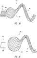
- Figures 10A-10B illustrate a device 650 having, according to the invention, a cylindrically or barrel-shaped first portion 652 and a helically extending second portion 654.
- the device 650 is formed from a single, continuous piece of material such that the first and second portions 652, 654 are integrally connected with each other.
- Figure 10B illustrates placement of the device 650 into an aneurysm 12.
- the first portion 652 can be expanded into apposition with the vessel wall across the neck 16 of the aneurysm 12.
- the first portion 652 is configured to engage and press outwardly against the vessel wall at the neck 16, which can enable the device 650 to be useful in occluding wide neck aneurysms.
- the first portion 652 can engage the vessel wall such that the first portion 652 is anchored across the aneurysm neck 16, thereby preventing herniation of the second portion 654 from within the aneurysm 12.
- Figure 11 illustrates another example of a device 700 comprising a first portion 702 and a second portion 704.
- the first portion 702 can comprise a plurality of individual expandable components 710. Any of the examples disclosed herein can comprise a plurality of components along the first portion.
- the device 700 advantageously utilizes a series of expandable components 710 because the second portion 704 is shape set as a framing member 720.
- the framing member 720 can comprise a plurality of loops or otherwise define a frame or structure having a hollow interior into which the expandable component 710 can be inserted during deployment of the device 700.
- Figure 11 also illustrates that the second portion of examples of the device can be shape set into a generally flat member.
- the framing member 720 comprises a series of loops formed by a flattened member.
- additional coils or embolic material can be advanced through an open end of the framing member 720.
- Suitable braid materials, structures, and method for manufacturing the framing member are disclosed in commonly assigned U.S. Patent No. 6,168,622 to Mazzocchi , U.S. Patent No. 8,142,456, issued March 27, 2012 , U.S. Patent Application Publication No. 2011/0319926, filed on November 11, 2010 , and U.S. Patent Application Publication No. 2012/0330341, filed on June 22, 2011 .
- Braid materials may include stainless steel, nitinol cobalt chromium, or the like.
- the framing member 720 combined with the expandable components 710 and optionally, coils or other materials, can provide the benefit of providing good neck coverage while preventing embolic devices from herniating into the parent artery. Additionally, the use of such a system can also increase packing volume efficiency and achieve stasis.
- the open end or widest interstices of the framing member 720 can be positioned at the neck of the aneurysm so as to facilitate insertion of the expandable components 710 and any additional material via a catheter, which can be placed into the open end or interstices of the framing member 720.
- the braid pattern can be properly aligned to facilitate entry of the materials into the framing structure.
- the framing structure can comprise a radiopaque material or component that facilitates visualization and enables the clinician to align the framing structure as needed within the aneurysm.
- the injection of a liquid embolic can increase the overall packing density or fill volume within the device.
- Onyx TM liquid embolic system manufactured by Covidien LP, Irvine, CA.
- Onyx TM liquid embolic system is a non-adhesive liquid used in the treatment of brain arteriovenous malformations.
- Onyx TM liquid embolic system is comprised of an EVOH (ethylene vinyl alcohol) copolymer dissolved in DMSO (dimethyl sulfoxide), and suspended micronized tantalum powder to provide contrast for visualization under fluoroscopy.
- EVOH ethylene vinyl alcohol
- DMSO dimethyl sulfoxide
- Other liquid embolic solutions are also envisioned.
- At least a portion of the device can comprise a coating or material for enhancing therapeutic, expansive, or imaging properties or characteristics of at least one or every expandable component of the device.
- At least a portion of the device can be coated with a biocompatible material to promote endothelialization or provide a therapeutic effect.
- the coating may include thrombogenic coatings such as fibrin, fibrinogen or the like, anti-thrombogenic coatings such as heparin (and derivatives thereof), or t-PA, and endothelial promoting coatings or facilitators such as, e.g., VEGF and RGD peptide, and/or combinations thereof.
- Drug eluting coatings and a drug eluting foam composite, such as anti-inflammatory or antibiotic, coatings are also envisioned.
- These drug eluting components may include nutrients, antibiotics, anti-inflammatory agents, antiplatelet agents, anesthetic agents such as lidocaine, and anti-proliferative agents, e.g. taxol derivatives such as paclitaxel. Hydrophilic, hygroscopic, and hydrophobic materials/agents are also envisioned.
- one or more portions of the device can also comprise an expansion-limiting coating that slows expansion of the component from its natural rate of expansion to a slower rate of expansion such that in the process of expanding, the position of the component can be adjusted within the aneurysm or the component can be removed from the aneurysm, if necessary.
- polymers that can be used as expansion-limiting coatings can include hydrophobic polymers, organic non-polar polymers, PTFE, polyethylene, polyphenylene sulfide, oils, and other similar materials.
- the device may be embedded or coated with an agent to provide desired characteristics to the expandable component(s).
- the device can comprise a non-thrombogenic coating applied to less than the entire first portion or second portion to minimize clotting at this location.
- Such coatings may be desirable in aneurysms located at a bifurcation such that blood flow to branch arteries is permitted through the segment of the foam structure having the non-thrombogenic coating.
- the coated area may be a different color than the remaining portion of the expandable component to assist the surgeon in identifying this area.
- the coated area can also comprise radiopaque material to assist the surgeon in visualization and placement of portions of the device in a desired orientation relative to the aneurysm.
- the device can have radiopacity characteristics either by adding radiopaque filler to the piece of material, such as bismuth, or attaching radiopaque markers.
- a radiopaque material can be attached to the device, such as by dipping, spraying, or otherwise mechanically, chemically, or thermally attached, injected into, or blended into to the device.
- the clinician can position the device by manually rotating, moving, maintaining the position of, or otherwise adjusting the position of the device within the aneurysm as the device expands.
- the clinician can adjust the device to ensure proper orientation of the device within the aneurysm.
- the position of the expandable device can be manipulated using various deployment or delivery devices.
- any of the embodiments can comprise an average porosity that varies spatially, any of the variety of disclosed shapes, any of the various disclosed materials or coatings, any of the disclosed 2-D or 3-D interconnected configurations, any of the disclosed inter-engagement configurations or structures, any of the disclosed delivery systems, etc.
- the apparatus and methods discussed herein are not limited to the deployment and use of a medical device or stent within the vascular system but may include any number of further treatment applications.
- Other treatment sites may include areas or regions of the body including any hollow anatomical structures.
- the phrase "at least one of' preceding a series of items, with the term “and” or “or” to separate any of the items, modifies the list as a whole, rather than each member of the list (i.e., each item).
- phrases “at least one of A, B, and C” or “at least one of A, B, or C” each refer to only A, only B, or only C; any combination of A, B, and C; and/or at least one of each of A, B, and C.
- top should be understood as referring to an arbitrary frame of reference, rather than to the ordinary gravitational frame of reference.
- a top surface, a bottom surface, a front surface, and a rear surface may extend upwardly, downwardly, diagonally, or horizontally in a gravitational frame of reference.
Description
- The present invention relates to occlusive devices for aneurysm therapy.
- Walls of the vasculature, particularly arterial walls, may develop areas of pathological dilatation called aneurysms. As is well known, aneurysms have thin, weak walls that are prone to rupturing. Aneurysms can be the result of the vessel wall being weakened by disease, injury or a congenital abnormality. Aneurysms could be found in different parts of the body with the most common being abdominal aortic aneurysms and brain or cerebral aneurysms in the neurovasculature. When the weakened wall of an aneurysm ruptures, it can result in death, especially if it is a cerebral aneurysm that ruptures.
- Aneurysms are generally treated by excluding the weakened part of the vessel from the arterial circulation. For treating a cerebral aneurysm, such reinforcement is done in many ways including: (i) surgical clipping, where a metal clip is secured around the base of the aneurysm; (ii) packing the aneurysm with small, flexible wire coils (micro-coils); (iii) using embolic materials to "fill" or "pack" an aneurysm; (iv) using detachable balloons or coils to occlude the parent vessel that supplies the aneurysm; and (v) intravascular stenting.
- In conventional methods of introducing a compressed stent into a vessel and positioning it within in an area of stenosis or an aneurysm, a guiding catheter having a distal tip is percutaneously introduced into the vascular system of a patient. The guiding catheter is advanced within the vessel until its distal tip is proximate the stenosis or aneurysm. A guidewire positioned within an inner lumen of a second, inner catheter and the inner catheter are advanced through the distal end of the guiding catheter. The guidewire is then advanced out of the distal end of the guiding catheter into the vessel until the distal portion of the guidewire carrying the compressed stent is positioned at the point of the lesion within the vessel. Once the compressed stent is located at the lesion, the stent may be released and expanded so that it supports the vessel.
- Numerous companies have pursued ball-type embolization devices for aneurysm treatment. Generally, braid-ball embolic devices for aneurysm treatment and/or other types of embolization operate through blood flow disruption and subsequent thrombus formation.
- The braid density of the device has an effect on blood flow through the device. Greater braid density in the implant results in greater flow disruption, less time to occlusion, and/or improved likelihood of durable occlusion. The size of microcatheter through which the device can be tracked to achieve endovascular access sets the primary limitation on the amount of braid (i.e., size and number of filaments) that may be included in the device. Device configuration for tracking then becomes the remaining design variable that can be leveraged to achieve desired performance.
US2013/0066357 andUS 6 168 622 B1 disclose devices and methods for the treatment of vascular defects. - The present invention is defined in the appended claims.
- Various features of illustrative embodiments are described below with reference to the drawings. The illustrated embodiments are intended to illustrate, but not to limit, the disclosure. The invention is shown in
figures 10A and 10B . - The drawings contain the following figures:
-
Figure 1 is a cross-sectional side view of an implant expanded within an aneurysm, according to some examples. -
Figure 2 is a side view of an implant, according to some examples. -
Figures 3A-3C are partial side, cross-sectional views of an implant in stages of deployment from a delivery catheter, according to some examples. -
Figures 4A-4B are side, cross-sectional views of transition sections of implants, according to some examples. -
Figure 5 is a side, cross-sectional view of a single layer implant, according to some examples. -
Figures 6A-6C illustrate steps in a process for manufacturing an implant, according to some examples. -
Figure 7 is a side, cross-sectional view of a dual layer implant, according to some examples. -
Figures 8A-8C illustrate steps in a process for manufacturing an implant, according to some examples. -
Figure 9A is a perspective view of a configuration of an implant, according to some examples. -
Figure 9B is a side, cross-sectional view of the implant ofFigure 9A released into an aneurysm, according to some examples. -
Figure 10A is a perspective view of another configuration of an implant, according to the invention. -
Figure 10B is a side, cross-sectional view of the implant ofFigure 10A released into an aneurysm. -
Figure 11 is a perspective view of yet another configuration of an implant, according to some examples. - In the following detailed description, numerous specific details are set forth to provide a full understanding of the subject technology. It should be understood that the subject technology may be practiced without some of these specific details. In other instances, well-known structures and techniques have not been shown in detail so as not to obscure the subject technology.
- Further, while the present description sets forth specific details of various embodiments, it will be appreciated that the description is illustrative only and should not be construed in any way as limiting. Additionally, it is contemplated that although particular embodiments may be disclosed or shown in the context of aneurysm therapy, such embodiments can be used in other applications for occluding vessels. Furthermore, various applications of such embodiments and modifications thereto, which may occur to those who are skilled in the art, are also encompassed by the general concepts described herein.
- Delivery systems, implants, and methods of making the implants are provided herein. The implant can be useful for treating neurovascular defects. One use is in intracranial aneurysm embolization/occlusion and another in parent vessel occlusion (PVO) or sacrifice. Further, some embodiments can comprise features related to certain aspects of the present assignee's
U.S. Patent No. 8,142,456 . - An embolization implant or device can comprise two or more sections having different shapes or configurations, which can enable the device to provide distinct functions or operational characteristics. The device can comprise a single, continuous piece of material that extends along each of the sections thereof. The piece of material can be shape set such that each of the sections achieves a desired shape or configuration. Accordingly, because some of the disclosed devices use only a single piece of material, the device can advantageously integrate various functions previously performed by several devices into a continuous device. This allows the device to perform various discrete functions while operating as a unitary or single component.
- For example, some implants can be formed from tubular braid stock comprising a resilient material such as Nitinol, that defines an open volume (ellipsoidal, spheroidal, spherical, substantially spherical/round, heart-shaped, ovoid, barrel-shaped or otherwise configured in cross section, etc.) in an uncompressed/unconstrained state. The device can be set within an aneurysm sac, such as at a vascular bifurcation. The implant can be delivered by access through the trunk vessel (e.g., the basilar artery), preferably through a commercially available microcatheter (not shown) with a delivery system, such as that described herein.
- The device can comprise at least two portions: a first portion comprising an atraumatic tip, neck blocking, or framing portion, and a second portion comprising a volume-filling portion. In some embodiments, the first section can be configured to precede the second section when being placed into a body lumen that is to be occluded, such as an aneurysm. The first portion or component of the device can be shape set to provide a function related to atraumatic entry into aneurysm or framing of an aneurysm. Further, a second portion, tip portion, or component of the device can be shape set to expand into one or more expandable components that can be advanced into an aneurysm to fill or pack the aneurysmal space or block the neck or ostium of the aneurysm to prevent herniation of embolic material therefrom. However, the order of placement can also be reversed, such as when the first section comprises a neck blocking portion.
- In some embodiments, the first portion of the device can be shape set to a minimal cross-sectional dimension, profile, or diameter. For example, the first portion of the device can be drawn down, e.g., twisted or longitudinally straightened, to a minimum cross-sectional dimension and shape set such that when unconstrained, the first portion assumes the minimum cross-sectional dimension. Further, in some embodiments, the first portion can be shape set to provide a secondary configuration, such as a helical member or framing member. In some embodiments, the first portion can be shape set to comprise a flexible coil-type element or a series of interconnected expandable components. Thus, the first portion can, for example, serve an atraumatic protective, framing, or volume-filling function.
- In some embodiments, the second portion of the device can be shape set to expand from a minimum cross-sectional dimension, when unconstrained, to an expanded profile that is much greater than the unconstrained profile of the first portion. For example, the second portion can expand to a round, three-dimensional shape, such as an ellipsoid, a cup, a barrel, and combinations thereof. Thus, the second portion can serve, for example, a volume-filling or neck blocking function.
- Further, the second portion of the device can be shape set to a plurality of expandable interconnected components. For example, the second portion can expand into a series of interconnected ellipsoids. Various other shapes and features can be implemented, as discussed herein.
- In some embodiments, the device can have a predetermined configuration, whether or not the device has only a single or multiple expandable components. The predetermined configuration can be based on typical aneurysm shapes, thereby allowing selection of a specific device. However, individual components of a device can also be arranged based on desired properties.
- In some embodiments, expandable component(s) of the first or second portions of the device may be shape set or manufactured into a variety of geometrical or partial geometrical shapes.
- For example, in order to accommodate a variety of aneurysm configurations, the shape or size of the expandable component(s) can be selected from a variety of spherical or non-spherical shapes, including, cylinders, hemispheres, noodles, polyhedrons (e.g., cuboids (types), tetrahedrons (e.g. pyramids), octahedrons, prisms), coils, prolate spheroids, oblate spheroids, plates (e.g., discs, polygonal plates), bowls (e.g,, an open container, such as a hollow, hemispherical container or other open, hollow containers, whether hemispherical, rounded, or otherwise), non-spherical surfaces of revolution (e.g., toruses, cones, cylinders, or other shapes rotated about a center point or a coplanar axis), and combinations thereof.
- A variety of delivery systems and procedures can be implemented to deliver a device having a specific size or shape and, in some embodiments, having a plurality of expandable components. Further, systems and methods are provided for delivery of a device to an aneurysm and/or recapturing the device for removal or repositioning. Examples of these systems and procedures are discussed further herein.
- Additionally, although in some embodiments, a single device can be used alone to fill the aneurysm and provide a desired packing density or fill volume, a plurality of devices can also be used to fill the aneurysm and provide a desired packing density or fill volume.
- Optionally, a liquid embolic and/or a framing component can be used in combination with one or more devices to facilitate delivery, engagement with the aneurysm, or increase of the packing density or fill volume. Any of these embodiments can allow increased packing density or fill volume to avoid recanalization of the aneurysm.
- Referring now to the drawings,
Figure 1 illustrates an example of anembolization device 10 positioned within ananeurysm 12 in ablood vessel 14. Thedevice 10 can be particularly adapted for use in the tortuous neurovasculature of a subject for at least partial deployment in a cerebral aneurysm. - A cerebral aneurysm may present itself in the shape of a berry, i.e., a so-called berry or saccular aneurysm, which is a bulge in the neurovascular vessel. Berry aneurysms may be located at bifurcations or other branched vessels. Other types of aneurysms, including fusiform aneurysms, can also be treated using examples of the devices disclosed herein.
- The
device 10 can comprise at least one expandable component. In some examples, thedevice 10 can comprise a plurality of expandable components. Further, a given expandable component of thedevice 10 can have one or more different characteristics than another of the expandable components of thedevice 10. An expandable component can be formed from a material that can be highly compressed and later expanded when released into the aneurysm and contacted by a fluid, such as a fluid within the aneurysm. - Referring now to
Figures 2-3C , some examples can provide adevice 100 having two or more expandable components. For example, thedevice 100 can comprise afirst portion 102 and asecond portion 104 that can each expand from a first or collapsed cross-sectional dimension or profile to an expanded cross-sectional dimension or profile. As discussed herein, thefirst portion 102 can comprise an expanded profile that is different in shape or size from the expanded profile of thesecond portion 104. As illustrated inFigure 3C , thefirst portion 102 can comprise a generally globular shape while thesecond portion 104 can comprise a bundled configuration that extends in a helical path. - The
device 100 can be formed from a continuous piece of material. For example, the material can comprise a plurality of braided filaments, a knitted material, or a woven material. Further, in some examples, thedevice 100 can comprise a tubular mesh that is shape set to define the first andsecond portions first portion 102, the tubular mesh can be shape set such that thefirst portion 102 defines an open volume and the filaments converge toward proximal anddistal ends - In accordance with some examples, the
first portion 102 can comprise any of a variety of three-dimensional shapes, such as ellipsoidal, spheroidal, spherical, substantially spherical/round, heart-shaped, ovoid, barrel-shaped, etc. In particular, in some examples, thefirst portion 102 can comprise a shape selected from the group consisting of cylinders, hemispheres, polyhedrons, prolate spheroids, oblate spheroids, plates, bowls, hollow structures, clover shapes, non-spherical surface of revolution, and combinations thereof. Additional expandable components can be provided that have substantially spherical shapes. - Additionally, the
second portion 104 can comprise a shape different from that of thefirst portion 102. For example, thesecond portion 104 can comprise a helical shape, a zig-zag shape, a sinusoidal shape, or any of a variety of three-dimensional forms. - The device and tip portion are shown as being formed from the plurality of braided filaments. The
second portion 104 can have a relatively large coil diameter (compared to the dimension of the first portion 102), which can create large coil loops. In some examples, a plurality of braided filaments can be bundled to form a coil having at least two and as many as ten loops. Further, in some examples, thesecond portion 104 can have between about three and about eight loops. Furthermore, in some examples, thesecond portion 104 can have about six loops. - Moreover, in some examples, the
second portion 104 can extend along edges of a three-dimensional shape such that thesecond portion 104 operates as a framing member when inserted into an aneurysm. - Optionally, the first and
second portions first portion 102 can be greater than an expanded profile of thesecond portion 104, as illustrated inFigure 2 . However, as shown inFigure 11 , which illustrates that the second portion of the device can be formed into a framing member, the second portion of the device can comprise an expanded profile that is greater than the expanded profile of the first portion. - In accordance with some examples, the profile, size, or shape of the first and
second portions first portion 102 can comprise a plurality of expandable components (see e.g.,elements 710 ofFigure 11 ). In such examples, the plurality of components can expand to different profiles, sizes, or shapes. Similarly, thesecond portion 104 can also expand to a variable profile. For example, thesecond portion 104 can be shape set into a helical member that extends along a variable helical path. Further, thesecond portion 104 can comprise a helical member and a framing member, according to some examples. - In accordance with some examples, methods of placing an embolization device within an aneurysm are also provided.
Figures 3A-3C illustrate a deployment sequence of adevice 100 is moved through acatheter 200. These figures illustrate various stages of expansion or recapture of thedevice 100 within thecatheter 200. In accordance with some examples of the methods disclosed herein, thedevice 100 can be partially released and recaptured into thecatheter 200 after initial deployment into the fundus of the aneurysm. The placement of thedevice 100 can therefore be carefully selected in order to provide superior placement within the aneurysm and optimal results. - In some examples in which the delivery system enables a clinician to retrieve or recapture the device, the delivery/retrieval member can comprise the Alligator Retrieval Device, manufactured by Covidien LP. The Alligator Retrieval Device can include a flexible wire having a plurality of gripping arms or elements, e.g., four arms, at the distal end of the flexible wire. Other examples for the gripping elements include a clover leaf design, fish hook design, or dissolvable coupling.
- Further, a suitable microcatheter adaptable for navigation through the tortuous neurovascular space to access the treatment site is disclosed in commonly assigned
U.S. Patent No. 7,507,229 . - As shown in
Figure 3A , thedevice 100 can be advanced towards adistal end 202 of thecatheter 200. In some examples, thedevice 100 can be pushed at the proximal end of thefirst section 102. However, thedevice 100 can also be pulled via attachment to a distal end of a guide wire or other member operative to advance thedevice 100 through thecatheter 200 by applying a distal force at adistal end 118 of thesecond portion 104. - The
catheter 200 can be selected such that an inner diameter of thelumen 204 closely approximates the first or collapsed, shape set cross-sectional dimension orprofile 210 of thesecond portion 104. For example, in some examples, thesecond portion 104 can be shape set to a diameter of 5.334mm (0.021 inches). While being advanced through thecatheter lumen 204, thesecond portion 104 can tend to avoid buckling if thecatheter lumen 204 closely approximates the shape set diameter of thesecond portion 104. Accordingly, in some examples, the diameter of thelumen 204 should be less than two times the cross-sectional dimension or diameter of the smallest portion of thedevice 100. Preferably, the diameter of thelumen 204 is less than two times the cross-sectional dimension or diameter of the smallest portion of thedevice 100. Further, the diameter of thelumen 204 can be less than 1 ½ times the cross-sectional dimension or diameter of the smallest portion of thedevice 100. - Advantageously, the
second portion 104 can provide a soft cushion or buffer for the device as thedevice 100 is placed into the aneurysm. Initially, thesecond portion 104 can be used to facilitate initial placement or location of thedevice 100 into the aneurysm. For example, thesecond portion 104 can be partially exposed (e.g., a sheath or catheter can be proximally retracted relative to thedevice 100 such that at least a portion of thesecond portion 104 extends from the distal opening of the sheath or catheter). The exposed portion of thesecond portion 104 can then be used to "anchor" or catch the assembly so that thedevice 100 and/or sheath/catheter can be further inserted into the aneurysm. - In some examples, the
device 100 can comprise a radiopaque marker. For example, the radiopaque marker can be placed at thedistal end 118 of thesecond portion 104. Accordingly, when advancing thedevice 100, the location and placement of thedevice 100 can be easily visualized under fluoroscopy. Further, in some examples, one or more filaments, materials, or coatings can be applied to either or both of the first andsecond portions - Once the
device 100 andcatheter 200 are properly positioned relative to the aneurysm (e.g., within the aneurysm or at least adjacent to the neck of the aneurysm so that thedevice 100 can be expanded into contact with the walls of the aneurysm), thedevice 100 can thereafter be expanded into contact with the walls of the aneurysm. - As shown in
Figure 3B , as thedevice 100 is advanced out of thedistal end 202 of thecatheter 200, thesecond portion 104 can expand. According to some examples, even when released from thecatheter 200, the cross-sectional dimension of thesecond portion 104 will not tend to expand beyond a shape set cross-sectional dimension or diameter of 0.533 mm (0.021 inches). Instead, thesecond portion 104 can expand to a secondary configuration, such as a helical member or framing member. - When released, as shown in
Figure 3C , thedevice 100 can expand from its first or collapsed configuration such that the first andsecond portions device 100 expands into contact with the walls of the aneurysm, thesecond portion 104 can provide a nest or volume of material against which the distal end, and in some examples, a marker or fastener at the distal end, can be placed. This can be especially advantageous to protect the aneurysm wall against any hub or noncompliant structure of the device (see e.g.,element 322 ofFigure 4B ). - For example, in some examples, the
second portion 104 can comprise a bundle of the braided filaments, thesecond portion 104 can provide a substantial cushion or buffer into which the distal end of thedevice 100 can be safely nestled. Features of these and other examples can advantageously serve to gather the second portion 104 (e.g., the bundle of braided filaments, in some examples) into a bunch configuration that can be interposed between the distal end of thedevice 100 and the aneurysm dome in order to prevent or avoid puncture of the aneurysm dome, as illustrated inFigure 1 . -
Figures 4A-4B illustrate side, cross-sectional views ofdevices Figure 4A , thedevices first portion 302 and asecond portion 304. As shown, thedevice 300 can comprise a single, continuous piece ofmaterial 310 that extends from thefirst portion 302 to thesecond portion 304. For example, thematerial 310 can comprise a tubular braid, knit, weave, or mesh. The tubular braid or mesh can comprise aninner lumen 312 that extends continuously from thefirst portion 302 to thesecond portion 304. However, as illustrated in bothFigures 4A-4B , the inner profile or dimension of thelumen 312 can comprise a substantially zero cross-sectional dimension in thesecond portion 304. In accordance with any of the examples disclosed herein, the cross-sectional dimension can comprise a diameter or width. - For example, the cross-sectional dimension can be "substantially zero" even if the
lumen 312 has open pockets. The term "substantially zero" can encompass configurations in which lumen 312 of thesecond portion 304 converges onto itself in a non-zero cross-sectional dimension, such as when thelumen 312 collapses with an inner surface thereof contacting itself in a shape set configuration. Furthermore, the term "substantially zero" can also refer to a contrasting (i.e., much smaller) size relative to the expanded dimension of thefirst portion 302. Indeed, when released from constraint, the cross-sectional dimension of thelumen 312 in thefirst portion 302 can expand to a degree much greater than thelumen 312 in thesecond portion 304. - Additionally, in accordance with some examples, the first and
second portions transition portion 314 whereat the material of thefirst portion 302 converges toward itself until achieving a substantially reduced profile whereatsecond portion 304 begins. In some examples, as shown inFigure 4A , thetransition portion 314 can be formed as a shape set configuration. However, in some examples, as shown inFigure 4B , thetransition portion 314 can further comprise ahub 322 that can secure the transition portion and urge thematerial 310 toward a reduced profile. - Referring now to
Figure 5 , another example of anembolization device 400 is shown. Thedevice 400 can comprise a single layer of material. For example, thedevice 400 can comprise a single layer of braided filaments. However, as illustrated inFigure 7 , at least a portion of anembolization device 500 can comprise multiple layers of material, such as braided filaments. - A process for manufacturing the
device 400 ofFigure 5 is illustrated inFigures 6A- 6C . As shown inFigure 5 ,device 400 comprises a generally globularfirst portion 402 and a generally helicalsecond portion 404. Initially, a singletubular braid 410 having a substantially constant inner dimension or profile is placed over afirst wire 420, as shown inFigure 6A . Thereafter, thebraid 410 can be placed over aform 430. In some examples, once theform 430 has been inserted into thebraid 410, acompression form 432 can be placed around thebraid 410. Thebraid 410 can then be shape set such that the portion of thebraid 410 fitted over theform 430 is shape set to a desired three-dimensional configuration. - Thereafter, a remaining
portion 440 of thebraid 410 can be longitudinally stretched, twisted, longitudinally straightened, or elongated along the longitudinal axis of thebraid 410. This stretching of thebraid 410 can draw down the cross-sectional dimension of thebraid 410 in the remainingportion 440. - In accordance with some examples, the remaining
portion 440 can also be physically modified. For example, one or more of the filaments of the remainingportion 440 can be cut and/or removed from the remainingportion 440. The alteration of the remainingportion 440 can facilitate the change of profile via shape setting and allow the second portion of the device to attain a desired configuration or profile. - When the remaining
portion 440 is drawn down to a desired profile, the remainingportion 440 can be wound around a mandrel orwire 450 and shape set to a desired three-dimensional shape. - Additionally, as shown in
Figure 7 , thedevice 500 can comprise a multilayer (shown in this example as a dual layer)first portion 502 and a single layersecond portion 504. Thefirst portion 502 can be formed from a tubular braid that can be everted or inverted onto itself such that the braid extends continuously into layers. For example, as illustrated inFigure 7 , atubular braid 510 can define afirst end 512 and asecond end 514. Additionally, thetubular braid 510 can define a foldedend 516. -
Figures 8A-8C illustrate an example of a process by which thedevice 500 can be formed. As shown, thebraid material 510 can be placed over awire 520. Asection 522 of thebraid material 510 can be pinched or tied down onto thewire 520, for example, using a filament tie. Thesection 522 can then become the foldedend 516 after asection 524 of thebraid material 510 is everted over thesection 522 and shape set in the step illustrated inFigure 8B . - As shown in
Figure 8B , once thesection 524 is everted, aform 530 can be inserted into thesecond end 514 of thebraid material 510. Acompression form 532 can then be positioned around thebraid material 510 and theform 530 in order to shape set thefirst portion 502 of thedevice 500, similar to the discussion noted above with respect toFigures 6B . Additionally, after thefirst portion 502 is shape set, thesecond portion 504 can be shape set by winding thebraid material 510 around amandrel 550 such that thesecond portion 504 is shape set to a desired configuration. Further details already discussed above with respect toFigures 6B-6C will not be repeated for brevity. - As such, in examples in which the device comprises an ellipsoidal shape, the ellipsoid can be enclosed within another ellipsoid to provide an ellipsoidal-shaped device having two layers. Thus, the first portion and/or the second portion of the device can comprise multiple layers. However, as shown in the example of
Figures 7-8C , although an additional layer can extend around the entire device or only around the second portion, some examples can advantageously be configured such that an additional layer extends only partially around the first or second portions of the device. - In accordance with some examples, the first portion of the device can comprise a volume-filling portion and/or a neck blocking portion, and the second portion of the device can comprise an atraumatic portion, volume filling portion, and/or a framing member. For example,
Figures 1-4B illustrate examples of a device in which the first portion thereof comprises a volume-filling portion and the second portion comprises an atraumatic portion.Figures 9A-10B illustrate examples of a device in which the first portion thereof comprises a neck blocking structure and the second portion comprises a volume-filling and/or atraumatic portion. Further,Figure 11 illustrates an example of the device in which the first portion comprises a volume-filling portion and the second portion of the device comprises a framing member. -
Figures 9A-9B illustrate adevice 600 having a cup-shapedfirst portion 602 and a helically extendingsecond portion 604. As discussed herein, thedevice 600 can be formed from a single, continuous piece of material such that the first andsecond portions -
Figure 9B illustrates placement of thedevice 600 into ananeurysm 12. As shown, thefirst portion 602 can be expanded into apposition with the vessel wall across theneck 16 of theaneurysm 12. Additionally, thefirst portion 602 can engage the vessel wall such that thefirst portion 602 is anchored across theaneurysm neck 16, thereby preventing herniation of thesecond portion 604 from within theaneurysm 12. - Similarly,
Figures 10A-10B illustrate adevice 650 having, according to the invention, a cylindrically or barrel-shapedfirst portion 652 and a helically extendingsecond portion 654. As also discussed herein, thedevice 650 is formed from a single, continuous piece of material such that the first andsecond portions -
Figure 10B illustrates placement of thedevice 650 into ananeurysm 12. As shown, thefirst portion 652 can be expanded into apposition with the vessel wall across theneck 16 of theaneurysm 12. Advantageously, thefirst portion 652 is configured to engage and press outwardly against the vessel wall at theneck 16, which can enable thedevice 650 to be useful in occluding wide neck aneurysms. Thefirst portion 652 can engage the vessel wall such that thefirst portion 652 is anchored across theaneurysm neck 16, thereby preventing herniation of thesecond portion 654 from within theaneurysm 12. -
Figure 11 illustrates another example of adevice 700 comprising afirst portion 702 and asecond portion 704. Thefirst portion 702 can comprise a plurality of individualexpandable components 710. Any of the examples disclosed herein can comprise a plurality of components along the first portion. Thedevice 700 advantageously utilizes a series ofexpandable components 710 because thesecond portion 704 is shape set as a framingmember 720. As illustrated, the framingmember 720 can comprise a plurality of loops or otherwise define a frame or structure having a hollow interior into which theexpandable component 710 can be inserted during deployment of thedevice 700. -
Figure 11 also illustrates that the second portion of examples of the device can be shape set into a generally flat member. As shown, the framingmember 720 comprises a series of loops formed by a flattened member. - In accordance with some examples, once the
device 700 has been placed in the aneurysm, additional coils or embolic material can be advanced through an open end of the framingmember 720. Suitable braid materials, structures, and method for manufacturing the framing member are disclosed in commonly assignedU.S. Patent No. 6,168,622 to Mazzocchi ,U.S. Patent No. 8,142,456, issued March 27, 2012 ,U.S. Patent Application Publication No. 2011/0319926, filed on November 11, 2010 , andU.S. Patent Application Publication No. 2012/0330341, filed on June 22, 2011 . Braid materials may include stainless steel, nitinol cobalt chromium, or the like. - The framing
member 720, combined with theexpandable components 710 and optionally, coils or other materials, can provide the benefit of providing good neck coverage while preventing embolic devices from herniating into the parent artery. Additionally, the use of such a system can also increase packing volume efficiency and achieve stasis. - In placing the framing
member 720 and theexpandable components 710 within an aneurysm, the open end or widest interstices of the framingmember 720 can be positioned at the neck of the aneurysm so as to facilitate insertion of theexpandable components 710 and any additional material via a catheter, which can be placed into the open end or interstices of the framingmember 720. In examples having a woven, knitted, braided, or mesh material for the framing structure, the braid pattern can be properly aligned to facilitate entry of the materials into the framing structure. As in other examples disclosed herein, the framing structure can comprise a radiopaque material or component that facilitates visualization and enables the clinician to align the framing structure as needed within the aneurysm. - The injection of a liquid embolic can increase the overall packing density or fill volume within the device.
- One suitable liquid embolic is the Onyx™ liquid embolic system manufactured by Covidien LP, Irvine, CA. Onyx™ liquid embolic system is a non-adhesive liquid used in the treatment of brain arteriovenous malformations. Onyx™ liquid embolic system is comprised of an EVOH (ethylene vinyl alcohol) copolymer dissolved in DMSO (dimethyl sulfoxide), and suspended micronized tantalum powder to provide contrast for visualization under fluoroscopy. Other liquid embolic solutions are also envisioned.
- In accordance with some embodiments, at least a portion of the device can comprise a coating or material for enhancing therapeutic, expansive, or imaging properties or characteristics of at least one or every expandable component of the device.
- In some embodiments, at least a portion of the device can be coated with a biocompatible material to promote endothelialization or provide a therapeutic effect.
- The coating may include thrombogenic coatings such as fibrin, fibrinogen or the like, anti-thrombogenic coatings such as heparin (and derivatives thereof), or t-PA, and endothelial promoting coatings or facilitators such as, e.g., VEGF and RGD peptide, and/or combinations thereof. Drug eluting coatings and a drug eluting foam composite, such as anti-inflammatory or antibiotic, coatings are also envisioned. These drug eluting components may include nutrients, antibiotics, anti-inflammatory agents, antiplatelet agents, anesthetic agents such as lidocaine, and anti-proliferative agents, e.g. taxol derivatives such as paclitaxel. Hydrophilic, hygroscopic, and hydrophobic materials/agents are also envisioned.
- In some embodiments, one or more portions of the device can also comprise an expansion-limiting coating that slows expansion of the component from its natural rate of expansion to a slower rate of expansion such that in the process of expanding, the position of the component can be adjusted within the aneurysm or the component can be removed from the aneurysm, if necessary. Examples of polymers that can be used as expansion-limiting coatings can include hydrophobic polymers, organic non-polar polymers, PTFE, polyethylene, polyphenylene sulfide, oils, and other similar materials.
- In some embodiments, only specific segments of the device may be embedded or coated with an agent to provide desired characteristics to the expandable component(s). For example, the device can comprise a non-thrombogenic coating applied to less than the entire first portion or second portion to minimize clotting at this location. Such coatings may be desirable in aneurysms located at a bifurcation such that blood flow to branch arteries is permitted through the segment of the foam structure having the non-thrombogenic coating. The coated area may be a different color than the remaining portion of the expandable component to assist the surgeon in identifying this area.
- Optionally, the coated area can also comprise radiopaque material to assist the surgeon in visualization and placement of portions of the device in a desired orientation relative to the aneurysm. The device can have radiopacity characteristics either by adding radiopaque filler to the piece of material, such as bismuth, or attaching radiopaque markers. Alternatively, a radiopaque material can be attached to the device, such as by dipping, spraying, or otherwise mechanically, chemically, or thermally attached, injected into, or blended into to the device.
- According to some embodiments, if the device has a specific characteristic, such as a porosity profile, coating, shape, etc., intended for placement in a certain location of the aneurysm, the clinician can position the device by manually rotating, moving, maintaining the position of, or otherwise adjusting the position of the device within the aneurysm as the device expands. Thus, by gently manipulating the device, the clinician can adjust the device to ensure proper orientation of the device within the aneurysm. The position of the expandable device can be manipulated using various deployment or delivery devices.
- Many of the features discussed herein can be used with any of the disclosed embodiments. For example, any of the embodiments can comprise an average porosity that varies spatially, any of the variety of disclosed shapes, any of the various disclosed materials or coatings, any of the disclosed 2-D or 3-D interconnected configurations, any of the disclosed inter-engagement configurations or structures, any of the disclosed delivery systems, etc.
- The apparatus and methods discussed herein are not limited to the deployment and use of a medical device or stent within the vascular system but may include any number of further treatment applications. Other treatment sites may include areas or regions of the body including any hollow anatomical structures.
- The foregoing description is provided to enable a person skilled in the art to practice the various configurations described herein. While the subject technology has been particularly described with reference to the various figures and configurations, it should be understood that these are for illustration purposes only and should not be taken as limiting the scope of the subject technology.
- It is understood that the specific order or hierarchy of steps in the processes disclosed is an illustration of exemplary approaches. Based upon design preferences, it is understood that the specific order or hierarchy of steps in the processes may be rearranged. Some of the steps may be performed simultaneously.
- As used herein, the phrase "at least one of' preceding a series of items, with the term "and" or "or" to separate any of the items, modifies the list as a whole, rather than each member of the list (i.e., each item). The phrase "at least one of' does not require selection of at least one of each item listed; rather, the phrase allows a meaning that includes at least one of any one of the items, and/or at least one of any combination of the items, and/or at least one of each of the items. By way of example, the phrases "at least one of A, B, and C" or "at least one of A, B, or C" each refer to only A, only B, or only C; any combination of A, B, and C; and/or at least one of each of A, B, and C.
- Terms such as "top," "bottom," "front," "rear" and the like as used in this disclosure should be understood as referring to an arbitrary frame of reference, rather than to the ordinary gravitational frame of reference. Thus, a top surface, a bottom surface, a front surface, and a rear surface may extend upwardly, downwardly, diagonally, or horizontally in a gravitational frame of reference.
- Furthermore, to the extent that the term "include," "have," or the like is used in the description or the claims, such term is intended to be inclusive in a manner similar to the term "comprise" as "comprise" is interpreted when employed as a transitional word in a claim.
- The word "exemplary" is used herein to mean "serving as an example, instance, or illustration." Any embodiment described herein as "exemplary" is not necessarily to be construed as preferred or advantageous over other embodiments.
- A reference to an element in the singular is not intended to mean "one and only one" unless specifically stated, but rather "one or more." Pronouns in the masculine (e.g., his) include the feminine and neuter gender (e.g., her and its) and vice versa. The term "some" refers to one or more. Underlined and/or italicized headings and subheadings are used for convenience only, do not limit the subject technology, and are not referred to in connection with the interpretation of the description of the subject technology. All structural and functional equivalents to the elements of the various configurations described throughout this disclosure that are known to those of ordinary skill in the art are intended to be encompassed by the subject technology.
- Although the detailed description contains many specifics, these should not be construed as limiting the scope of the subject technology but merely as illustrating different examples and aspects of the subject technology. It should be appreciated that the scope of the subject technology includes other embodiments not discussed in detail above. Various other modifications, changes and variations may be made in the arrangement, operation and details of the apparatus of the subject technology disclosed herein without departing from the scope of the present disclosure, as defined in the appended claims. Unless otherwise expressed, reference to an element in the singular is not intended to mean "one and only one" unless explicitly stated, but rather is meant to mean "one or more." In addition, it is not necessary for a device or method to address every problem that is solvable (or possess every advantage that is achievable) by different embodiments of the disclosure in order to be encompassed within the scope of the disclosure. The use herein of "can" and derivatives thereof shall be understood in the sense of "possibly" or "optionally" as opposed to an affirmative capability.
Claims (4)
- An aneurysm embolization device (650), comprising:a body portion (652) having a first end (114) and being self-expandable to a first expanded configuration in which the body portion (652) has a cylindrical or barrel shape, wherein, when the device (650) is positioned in an aneurysm, the body portion (652) is configured to expand into apposition with a vessel wall across the neck of the aneurysm and press outwardly against the vessel wall at the neck such that the body portion (652) is anchored across the neck; andan atraumatic tip portion (654) extending from the first end (114) of the body portion and being self-expandable to a second expanded configuration;wherein the body portion (652) and the tip portion (654) comprise a single, continuous tubular braid formed of a plurality of filaments of a resilient material, characterized in that the tip portion (654) is shape-set as a helical member.
- The device (650) of Claim 1, wherein in a compressed state, the body portion (653) and the tip portion (654) comprise an outer diameter of between about 0.254mm to about 1.27mm (about 0.010" and about 0.050").
- The device (650) of any of Claim 1 or Claim 2, wherein in a compressed state, the body portion and the tip portion comprise an outer diameter of between about 0.391mm to about 0.762mm (about 0.015" and about 0.030").
- The device (650) of any of Claims 1 to 3, wherein the body portion (652) comprises a folded end, opposite the first end (114), whereat the layers of braided filaments meet.
Applications Claiming Priority (2)
| Application Number | Priority Date | Filing Date | Title |
|---|---|---|---|
| US201361789423P | 2013-03-15 | 2013-03-15 | |
| PCT/US2014/029613 WO2014144980A1 (en) | 2013-03-15 | 2014-03-14 | Occlusive device |
Publications (2)
| Publication Number | Publication Date |
|---|---|
| EP2967571A1 EP2967571A1 (en) | 2016-01-20 |
| EP2967571B1 true EP2967571B1 (en) | 2022-08-31 |
Family
ID=50442745
Family Applications (1)
| Application Number | Title | Priority Date | Filing Date |
|---|---|---|---|
| EP14716201.0A Active EP2967571B1 (en) | 2013-03-15 | 2014-03-14 | Occlusive device |
Country Status (4)
| Country | Link |
|---|---|
| US (3) | US10736758B2 (en) |
| EP (1) | EP2967571B1 (en) |
| CN (2) | CN105142545B (en) |
| WO (1) | WO2014144980A1 (en) |
Families Citing this family (82)
| Publication number | Priority date | Publication date | Assignee | Title |
|---|---|---|---|---|
| DK2265193T3 (en) | 2008-04-21 | 2012-01-23 | Nfocus Neuromedical Inc | Embolic devices with braided ball and delivery systems |
| US11471164B2 (en) | 2008-05-01 | 2022-10-18 | Aneuclose Llc | Methods of occluding a cerebral aneurysm by inserting embolic members or material into an intrasacular implant |
| US11357511B2 (en) | 2008-05-01 | 2022-06-14 | Aneuclose Llc | Intrasacular aneurysm occlusion device with globular first configuration and bowl-shaped second configuration |
| US11464518B2 (en) | 2008-05-01 | 2022-10-11 | Aneuclose Llc | Proximal concave neck bridge with central lumen and distal net for occluding cerebral aneurysms |
| US11484322B2 (en) | 2018-01-03 | 2022-11-01 | Aneuclose Llc | Aneurysm neck bridge with a closeable opening or lumen through which embolic material is inserted into the aneurysm sac |
| US11583289B2 (en) | 2008-05-01 | 2023-02-21 | Aneuclose Llc | Aneurysm-occluding mesh ribbon with a series of loops or segments having distal-to-proximal variation in size, shape, and/or orientation |
| US9675482B2 (en) | 2008-05-13 | 2017-06-13 | Covidien Lp | Braid implant delivery systems |
| WO2013119332A2 (en) | 2012-02-09 | 2013-08-15 | Stout Medical Group, L.P. | Embolic device and methods of use |
| US20140135811A1 (en) | 2012-11-13 | 2014-05-15 | Covidien Lp | Occlusive devices |
| US9955976B2 (en) * | 2013-08-16 | 2018-05-01 | Sequent Medical, Inc. | Filamentary devices for treatment of vascular defects |
| JP6661539B2 (en) | 2013-12-20 | 2020-03-11 | テルモ株式会社 | Vessel closure |
| AU2015222866A1 (en) * | 2014-02-27 | 2016-09-15 | Incumedx, Inc. | Embolic framing microcoils |
| US11154302B2 (en) | 2014-03-31 | 2021-10-26 | DePuy Synthes Products, Inc. | Aneurysm occlusion device |
| US11076860B2 (en) | 2014-03-31 | 2021-08-03 | DePuy Synthes Products, Inc. | Aneurysm occlusion device |
| US9713475B2 (en) * | 2014-04-18 | 2017-07-25 | Covidien Lp | Embolic medical devices |
| WO2015184075A1 (en) | 2014-05-28 | 2015-12-03 | Stryker European Holdings I, Llc | Vaso-occlusive devices and methods of use |
| JP5783301B1 (en) | 2014-06-11 | 2015-09-24 | 富士ゼロックス株式会社 | Communication terminal, communication system, and program |
| US9814466B2 (en) | 2014-08-08 | 2017-11-14 | Covidien Lp | Electrolytic and mechanical detachment for implant delivery systems |
| US9918718B2 (en) | 2014-08-08 | 2018-03-20 | DePuy Synthes Products, Inc. | Embolic coil delivery system with retractable mechanical release mechanism |
| US10736730B2 (en) | 2015-01-20 | 2020-08-11 | Neurogami Medical, Inc. | Vascular implant |
| US11484319B2 (en) | 2015-01-20 | 2022-11-01 | Neurogami Medical, Inc. | Delivery system for micrograft for treating intracranial aneurysms |
| WO2016118420A1 (en) | 2015-01-20 | 2016-07-28 | Neurogami Medical, Inc. | Micrograft for the treatment of intracranial aneurysms and method for use |
| US10857012B2 (en) | 2015-01-20 | 2020-12-08 | Neurogami Medical, Inc. | Vascular implant |
| US10925611B2 (en) | 2015-01-20 | 2021-02-23 | Neurogami Medical, Inc. | Packaging for surgical implant |
| EP3261703A4 (en) | 2015-02-25 | 2018-10-24 | Galaxy Therapeutics, LLC | System for and method of treating aneurysms |
| US10159490B2 (en) | 2015-05-08 | 2018-12-25 | Stryker European Holdings I, Llc | Vaso-occlusive devices |
| CN105105812A (en) * | 2015-09-18 | 2015-12-02 | 王奎重 | Intracranial aneurysm interventional embolization treatment device |
| US10314593B2 (en) * | 2015-09-23 | 2019-06-11 | Covidien Lp | Occlusive devices |
| CN114732470A (en) * | 2015-12-30 | 2022-07-12 | 斯瑞克公司 | Embolization device and method of making same |
| EP3463109A4 (en) * | 2016-05-26 | 2020-01-08 | Nanostructures, Inc. | System and methods for embolized occlusion of neurovascular aneurysms |
| US10420563B2 (en) | 2016-07-08 | 2019-09-24 | Neurogami Medical, Inc. | Delivery system insertable through body lumen |
| US10576099B2 (en) | 2016-10-21 | 2020-03-03 | Covidien Lp | Injectable scaffold for treatment of intracranial aneurysms and related technology |
| JP7139346B2 (en) | 2017-02-23 | 2022-09-20 | デピュイ・シンセス・プロダクツ・インコーポレイテッド | Aneurysm device and delivery system |
| WO2019027966A1 (en) | 2017-07-31 | 2019-02-07 | Boston Scientific Scimed, Inc. | Dilator with engagement region |
| EP3668419B1 (en) | 2017-08-15 | 2024-04-03 | Boston Scientific Scimed, Inc. | Occlusive medical device system |
| US10675036B2 (en) | 2017-08-22 | 2020-06-09 | Covidien Lp | Devices, systems, and methods for the treatment of vascular defects |
| US10874402B2 (en) | 2017-10-10 | 2020-12-29 | Boston Scientific Scimed, Inc. | Detachable RF energized occlusive device |
| US10806462B2 (en) | 2017-12-21 | 2020-10-20 | DePuy Synthes Products, Inc. | Implantable medical device detachment system with split tube and cylindrical coupling |
| US10716574B2 (en) | 2017-12-22 | 2020-07-21 | DePuy Synthes Products, Inc. | Aneurysm device and delivery method |
| US10751065B2 (en) | 2017-12-22 | 2020-08-25 | DePuy Synthes Products, Inc. | Aneurysm device and delivery system |
| US11185335B2 (en) * | 2018-01-19 | 2021-11-30 | Galaxy Therapeutics Inc. | System for and method of treating aneurysms |
| US10905430B2 (en) | 2018-01-24 | 2021-02-02 | DePuy Synthes Products, Inc. | Aneurysm device and delivery system |
| CN111936063A (en) | 2018-01-31 | 2020-11-13 | 纳米结构公司 | Vascular occlusion device using thin film nitinol foil |
| CN111670021B (en) | 2018-02-01 | 2023-08-04 | 波士顿科学国际有限公司 | Medical device release system |
| US11284902B2 (en) | 2018-02-01 | 2022-03-29 | Boston Scientific Scimed, Inc. | Method of making a vascular occlusion device |
| US11058430B2 (en) * | 2018-05-25 | 2021-07-13 | DePuy Synthes Products, Inc. | Aneurysm device and delivery system |
| US11596412B2 (en) * | 2018-05-25 | 2023-03-07 | DePuy Synthes Products, Inc. | Aneurysm device and delivery system |
| US10939915B2 (en) | 2018-05-31 | 2021-03-09 | DePuy Synthes Products, Inc. | Aneurysm device and delivery system |
| US11051825B2 (en) | 2018-08-08 | 2021-07-06 | DePuy Synthes Products, Inc. | Delivery system for embolic braid |
| US11123077B2 (en) | 2018-09-25 | 2021-09-21 | DePuy Synthes Products, Inc. | Intrasaccular device positioning and deployment system |
| US11076861B2 (en) | 2018-10-12 | 2021-08-03 | DePuy Synthes Products, Inc. | Folded aneurysm treatment device and delivery method |
| US11564692B2 (en) | 2018-11-01 | 2023-01-31 | Terumo Corporation | Occlusion systems |
| US11406392B2 (en) | 2018-12-12 | 2022-08-09 | DePuy Synthes Products, Inc. | Aneurysm occluding device for use with coagulating agents |
| CN111388045A (en) | 2018-12-17 | 2020-07-10 | 柯惠有限合伙公司 | Occlusion device |
| US11272939B2 (en) | 2018-12-18 | 2022-03-15 | DePuy Synthes Products, Inc. | Intrasaccular flow diverter for treating cerebral aneurysms |
| US20220087680A1 (en) * | 2018-12-26 | 2022-03-24 | Endostream Medical Ltd. | Devices for treating vascular malformations |
| US11134953B2 (en) | 2019-02-06 | 2021-10-05 | DePuy Synthes Products, Inc. | Adhesive cover occluding device for aneurysm treatment |
| US20200305885A1 (en) * | 2019-03-27 | 2020-10-01 | DePuy Synthes Products, Inc. | Aneurysm treatment device |
| US11337706B2 (en) | 2019-03-27 | 2022-05-24 | DePuy Synthes Products, Inc. | Aneurysm treatment device |
| US11602350B2 (en) | 2019-12-05 | 2023-03-14 | DePuy Synthes Products, Inc. | Intrasaccular inverting braid with highly flexible fill material |
| US11278292B2 (en) | 2019-05-21 | 2022-03-22 | DePuy Synthes Products, Inc. | Inverting braided aneurysm treatment system and method |
| US10653425B1 (en) | 2019-05-21 | 2020-05-19 | DePuy Synthes Products, Inc. | Layered braided aneurysm treatment device |
| US11672542B2 (en) | 2019-05-21 | 2023-06-13 | DePuy Synthes Products, Inc. | Aneurysm treatment with pushable ball segment |
| US11413046B2 (en) | 2019-05-21 | 2022-08-16 | DePuy Synthes Products, Inc. | Layered braided aneurysm treatment device |
| US11607226B2 (en) | 2019-05-21 | 2023-03-21 | DePuy Synthes Products, Inc. | Layered braided aneurysm treatment device with corrugations |
| US11497504B2 (en) | 2019-05-21 | 2022-11-15 | DePuy Synthes Products, Inc. | Aneurysm treatment with pushable implanted braid |
| US10856880B1 (en) | 2019-05-25 | 2020-12-08 | Galaxy Therapeutics, Inc. | Systems and methods for treating aneurysms |
| US11426174B2 (en) | 2019-10-03 | 2022-08-30 | DePuy Synthes Products, Inc. | Medical device delivery member with flexible stretch resistant mechanical release |
| US11672946B2 (en) | 2019-09-24 | 2023-06-13 | Boston Scientific Scimed, Inc. | Protection and actuation mechanism for controlled release of implantable embolic devices |
| US11685007B2 (en) | 2019-11-04 | 2023-06-27 | Covidien Lp | Devices, systems, and methods for treatment of intracranial aneurysms |
| US11376013B2 (en) | 2019-11-18 | 2022-07-05 | DePuy Synthes Products, Inc. | Implant delivery system with braid cup formation |
| US11457926B2 (en) | 2019-12-18 | 2022-10-04 | DePuy Synthes Products, Inc. | Implant having an intrasaccular section and intravascular section |
| US11432822B2 (en) * | 2020-02-14 | 2022-09-06 | DePuy Synthes Products, Inc. | Intravascular implant deployment system |
| US11931041B2 (en) | 2020-05-12 | 2024-03-19 | Covidien Lp | Devices, systems, and methods for the treatment of vascular defects |
| US11951026B2 (en) | 2020-06-30 | 2024-04-09 | DePuy Synthes Products, Inc. | Implantable medical device detachment system with flexible braid section |
| US11134954B1 (en) * | 2021-02-01 | 2021-10-05 | Accumedical Beijing Ltd. | Braided embolization apparatus |
| CN113855145B (en) * | 2021-10-29 | 2023-06-30 | 微创神通医疗科技(上海)有限公司 | Hemangioma plugging device, hemangioma plugging treatment device and hemangioma plugging system |
| US11937824B2 (en) | 2021-12-30 | 2024-03-26 | DePuy Synthes Products, Inc. | Implant detachment systems with a modified pull wire |
| US11844490B2 (en) | 2021-12-30 | 2023-12-19 | DePuy Synthes Products, Inc. | Suture linkage for inhibiting premature embolic implant deployment |
| WO2023172656A1 (en) * | 2022-03-08 | 2023-09-14 | Beaty Narlin | Flow diverter devices and associated methods and systems |
| US11937825B2 (en) | 2022-03-02 | 2024-03-26 | DePuy Synthes Products, Inc. | Hook wire for preventing premature embolic implant detachment |
| US11937826B2 (en) | 2022-03-14 | 2024-03-26 | DePuy Synthes Products, Inc. | Proximal link wire for preventing premature implant detachment |
Family Cites Families (467)
| Publication number | Priority date | Publication date | Assignee | Title |
|---|---|---|---|---|
| US3108593A (en) | 1961-03-13 | 1963-10-29 | Jacob A Glassman | Surgical extractor |
| DE1283434B (en) | 1963-06-25 | 1968-11-21 | Dr Jacob A Glassmann | Instrument for introducing into natural body canals and for capturing and bringing out foreign bodies in them |
| US4425908A (en) | 1981-10-22 | 1984-01-17 | Beth Israel Hospital | Blood clot filter |
| SE445884B (en) | 1982-04-30 | 1986-07-28 | Medinvent Sa | DEVICE FOR IMPLANTATION OF A RODFORM PROTECTION |
| US5190546A (en) | 1983-10-14 | 1993-03-02 | Raychem Corporation | Medical devices incorporating SIM alloy elements |
| FR2556210B1 (en) | 1983-12-08 | 1988-04-15 | Barra Jean Aubert | VENOUS PROSTHESIS AND PROCESS FOR PRODUCING THE SAME |
| US5749920A (en) | 1983-12-09 | 1998-05-12 | Endovascular Technologies, Inc. | Multicapsule intraluminal grafting system and method |
| DK151404C (en) | 1984-05-23 | 1988-07-18 | Cook Europ Aps William | FULLY FILTER FOR IMPLANTATION IN A PATIENT'S BLOOD |
| EP0556940A1 (en) | 1986-02-24 | 1993-08-25 | Robert E. Fischell | Intravascular stent |
| SE453258B (en) | 1986-04-21 | 1988-01-25 | Medinvent Sa | ELASTIC, SELF-EXPANDING PROTEST AND PROCEDURE FOR ITS MANUFACTURING |
| WO1988000813A1 (en) | 1986-08-05 | 1988-02-11 | St. Jude Medical, Inc. | Braided polyester vascular prosthesis and method |
| FR2624747A1 (en) | 1987-12-18 | 1989-06-23 | Delsanti Gerard | REMOVABLE ENDO-ARTERIAL DEVICES FOR REPAIRING ARTERIAL WALL DECOLLEMENTS |
| US4921484A (en) | 1988-07-25 | 1990-05-01 | Cordis Corporation | Mesh balloon catheter device |
| DE9010130U1 (en) | 1989-07-13 | 1990-09-13 | American Medical Systems, Inc., Minnetonka, Minn., Us | |
| CA2026604A1 (en) | 1989-10-02 | 1991-04-03 | Rodney G. Wolff | Articulated stent |
| US5545208A (en) | 1990-02-28 | 1996-08-13 | Medtronic, Inc. | Intralumenal drug eluting prosthesis |
| US6083220A (en) | 1990-03-13 | 2000-07-04 | The Regents Of The University Of California | Endovascular electrolytically detachable wire and tip for the formation of thrombus in arteries, veins, aneurysms, vascular malformations and arteriovenous fistulas |
| USRE42625E1 (en) | 1990-03-13 | 2011-08-16 | The Regents Of The University Of California | Endovascular electrolytically detachable wire and tip for the formation of thrombus in arteries, veins, aneurysms, vascular malformations and arteriovenous fistulas |
| US5354295A (en) | 1990-03-13 | 1994-10-11 | Target Therapeutics, Inc. | In an endovascular electrolytically detachable wire and tip for the formation of thrombus in arteries, veins, aneurysms, vascular malformations and arteriovenous fistulas |
| US5122136A (en) | 1990-03-13 | 1992-06-16 | The Regents Of The University Of California | Endovascular electrolytically detachable guidewire tip for the electroformation of thrombus in arteries, veins, aneurysms, vascular malformations and arteriovenous fistulas |
| US5221261A (en) | 1990-04-12 | 1993-06-22 | Schneider (Usa) Inc. | Radially expandable fixation member |
| US5158548A (en) | 1990-04-25 | 1992-10-27 | Advanced Cardiovascular Systems, Inc. | Method and system for stent delivery |
| US5064435A (en) | 1990-06-28 | 1991-11-12 | Schneider (Usa) Inc. | Self-expanding prosthesis having stable axial length |
| US5405379A (en) | 1990-07-26 | 1995-04-11 | Lane; Rodney J. | Self expanding vascular endoprosthesis for aneurysms |
| US5222971A (en) | 1990-10-09 | 1993-06-29 | Scimed Life Systems, Inc. | Temporary stent and methods for use and manufacture |
| USRE38711E1 (en) | 1991-03-08 | 2005-03-15 | Kabushikikaisha Igaki Iryo Sekkei | Luminal stent, holding structure therefor and device for attaching luminal stent |
| USRE38653E1 (en) | 1991-03-08 | 2004-11-16 | Kabushikikaisha Igaki Iryo Sekkei | Luminal stent, holding structure therefor and device for attaching luminal stent |
| US5766151A (en) | 1991-07-16 | 1998-06-16 | Heartport, Inc. | Endovascular system for arresting the heart |
| US5232648A (en) | 1991-07-19 | 1993-08-03 | United States Surgical Corporation | Bioabsorbable melt spun fiber based on glycolide-containing copolymer |
| US5527338A (en) | 1992-09-02 | 1996-06-18 | Board Of Regents, The University Of Texas System | Intravascular device |
| US5250071A (en) | 1992-09-22 | 1993-10-05 | Target Therapeutics, Inc. | Detachable embolic coil assembly using interlocking clasps and method of use |
| DE59206251D1 (en) | 1992-10-31 | 1996-06-13 | Schneider Europ Ag | Arrangement for implanting self-expanding endoprostheses |
| US5308356A (en) | 1993-02-25 | 1994-05-03 | Blackshear Jr Perry L | Passive perfusion angioplasty catheter |
| US5476495A (en) | 1993-03-16 | 1995-12-19 | Ep Technologies, Inc. | Cardiac mapping and ablation systems |
| WO1994021170A1 (en) | 1993-03-16 | 1994-09-29 | Ep Technologies, Inc. | Flexible circuit assemblies employing ribbon cable |
| US5334210A (en) | 1993-04-09 | 1994-08-02 | Cook Incorporated | Vascular occlusion assembly |
| US5545209A (en) | 1993-09-30 | 1996-08-13 | Texas Petrodet, Inc. | Controlled deployment of a medical device |
| RU2089131C1 (en) | 1993-12-28 | 1997-09-10 | Сергей Апполонович Пульнев | Stent-expander |
| FR2714815B1 (en) | 1994-01-10 | 1996-03-08 | Microfil Ind Sa | Elastic prosthesis to widen a duct, in particular a blood vessel. |
| US5549635A (en) | 1994-01-24 | 1996-08-27 | Solar, Rita & Gaterud, Ltd. | Non-deformable self-expanding parallel flow endovascular stent and deployment apparatus therefore |
| US20030032963A1 (en) | 2001-10-24 | 2003-02-13 | Kyphon Inc. | Devices and methods using an expandable body with internal restraint for compressing cancellous bone |
| WO1995023623A1 (en) | 1994-03-04 | 1995-09-08 | Mentor Corporation | Self-sealing injection sites and method of manufacture |
| US5634942A (en) | 1994-04-21 | 1997-06-03 | B. Braun Celsa | Assembly comprising a blood filter for temporary or definitive use and a device for implanting it |
| US6001092A (en) | 1994-06-24 | 1999-12-14 | Target Therapeutics, Inc. | Complex coils having fibered centers |
| US5846261A (en) | 1994-07-08 | 1998-12-08 | Aga Medical Corp. | Percutaneous catheter directed occlusion devices |
| WO1996001591A1 (en) | 1994-07-08 | 1996-01-25 | Microvena Corporation | Method of forming medical devices; intravascular occlusion devices |
| US5725552A (en) | 1994-07-08 | 1998-03-10 | Aga Medical Corporation | Percutaneous catheter directed intravascular occlusion devices |
| US6123715A (en) | 1994-07-08 | 2000-09-26 | Amplatz; Curtis | Method of forming medical devices; intravascular occlusion devices |
| US5702419A (en) | 1994-09-21 | 1997-12-30 | Wake Forest University | Expandable, intraluminal stents |
| US5690671A (en) | 1994-12-13 | 1997-11-25 | Micro Interventional Systems, Inc. | Embolic elements and methods and apparatus for their delivery |
| US5879366A (en) | 1996-12-20 | 1999-03-09 | W.L. Gore & Associates, Inc. | Self-expanding defect closure device and method of making and using |
| US5814062A (en) | 1994-12-22 | 1998-09-29 | Target Therapeutics, Inc. | Implant delivery assembly with expandable coupling/decoupling mechanism |
| ES2185746T3 (en) | 1995-03-30 | 2003-05-01 | Boston Scient Ltd | SYSTEM FOR THE IMPLANT OF LIQUID COILS WITH SECONDARY STRUCTURE. |
| BE1009278A3 (en) | 1995-04-12 | 1997-01-07 | Corvita Europ | Guardian self-expandable medical device introduced in cavite body, and medical device with a stake as. |
| CA2218072A1 (en) | 1995-04-14 | 1996-10-17 | Schneider (Usa) Inc. | Rolling membrane stent delivery device |
| US5645558A (en) | 1995-04-20 | 1997-07-08 | Medical University Of South Carolina | Anatomically shaped vasoocclusive device and method of making the same |
| US5911731A (en) | 1995-04-20 | 1999-06-15 | Target Therapeutics, Inc. | Anatomically shaped vasoocclusive devices |
| NO962336L (en) | 1995-06-06 | 1996-12-09 | Target Therapeutics Inc | Vaso-occlusive spiral |
| US5624461A (en) | 1995-06-06 | 1997-04-29 | Target Therapeutics, Inc. | Three dimensional in-filling vaso-occlusive coils |
| US5713907A (en) | 1995-07-20 | 1998-02-03 | Endotex Interventional Systems, Inc. | Apparatus and method for dilating a lumen and for inserting an intraluminal graft |
| US6689162B1 (en) | 1995-10-11 | 2004-02-10 | Boston Scientific Scimed, Inc. | Braided composite prosthesis |
| US5758562A (en) | 1995-10-11 | 1998-06-02 | Schneider (Usa) Inc. | Process for manufacturing braided composite prosthesis |
| ES2131253T3 (en) | 1995-11-14 | 1999-07-16 | Schneider Europ Gmbh | DEVICE FOR THE IMPLEMENTATION OF AN ENDOPROTESIS. |
| WO1997025918A1 (en) | 1996-01-19 | 1997-07-24 | Ep Technologies, Inc. | Electrode structures formed from flexible, porous, or woven materials |
| US6168622B1 (en) * | 1996-01-24 | 2001-01-02 | Microvena Corporation | Method and apparatus for occluding aneurysms |
| AU733332B2 (en) | 1996-02-02 | 2001-05-10 | Transvascular, Inc. | Methods and apparatus for blocking flow through blood vessels |
| US5733294A (en) | 1996-02-28 | 1998-03-31 | B. Braun Medical, Inc. | Self expanding cardiovascular occlusion device, method of using and method of making the same |
| JP3804690B2 (en) | 1996-03-11 | 2006-08-02 | 鹿島塩ビモノマー株式会社 | Heat recovery method and heat recovery apparatus in thermal decomposition process of 1,2-dichloroethane |
| US5853422A (en) | 1996-03-22 | 1998-12-29 | Scimed Life Systems, Inc. | Apparatus and method for closing a septal defect |
| US5792154A (en) | 1996-04-10 | 1998-08-11 | Target Therapeutics, Inc. | Soft-ended fibered micro vaso-occlusive devices |
| AR001590A1 (en) | 1996-04-10 | 1997-11-26 | Jorge Alberto Baccaro | Abnormal vascular communications occluder device and applicator cartridge of said device |
| US5718159A (en) | 1996-04-30 | 1998-02-17 | Schneider (Usa) Inc. | Process for manufacturing three-dimensional braided covered stent |
| US6440088B1 (en) | 1996-05-24 | 2002-08-27 | Precision Vascular Systems, Inc. | Hybrid catheter guide wire apparatus and method |
| US6666883B1 (en) | 1996-06-06 | 2003-12-23 | Jacques Seguin | Endoprosthesis for vascular bifurcation |
| US6190402B1 (en) | 1996-06-21 | 2001-02-20 | Musc Foundation For Research Development | Insitu formable and self-forming intravascular flow modifier (IFM) and IFM assembly for deployment of same |
| US6077295A (en) | 1996-07-15 | 2000-06-20 | Advanced Cardiovascular Systems, Inc. | Self-expanding stent delivery system |
| US6096034A (en) | 1996-07-26 | 2000-08-01 | Target Therapeutics, Inc. | Aneurysm closure device assembly |
| US5980514A (en) | 1996-07-26 | 1999-11-09 | Target Therapeutics, Inc. | Aneurysm closure device assembly |
| CA2263492C (en) | 1996-08-23 | 2006-10-17 | Scimed Life Systems, Inc. | Stent delivery system having stent securement apparatus |
| US5941249A (en) | 1996-09-05 | 1999-08-24 | Maynard; Ronald S. | Distributed activator for a two-dimensional shape memory alloy |
| US5968068A (en) | 1996-09-12 | 1999-10-19 | Baxter International Inc. | Endovascular delivery system |
| JP2001500987A (en) | 1996-09-23 | 2001-01-23 | ピーエスシー・スキャニング・インコーポレイテッド | Dithering mechanism for barcode scanner |
| US5957974A (en) | 1997-01-23 | 1999-09-28 | Schneider (Usa) Inc | Stent graft with braided polymeric sleeve |
| JP3523765B2 (en) | 1997-01-24 | 2004-04-26 | テルモ株式会社 | Living organ dilator |
| US6096073A (en) | 1997-02-25 | 2000-08-01 | Scimed Life Systems, Inc. | Method of deploying a stent at a lesion site located at a bifurcation in a parent vessel |
| US5830230A (en) | 1997-03-07 | 1998-11-03 | Micro Therapeutics, Inc. | Method of intracranial vascular embolotherapy using self anchoring coils |
| US5980554A (en) | 1997-05-05 | 1999-11-09 | Micro Therapeutics, Inc. | Wire frame partial flow obstruction for aneurysm treatment |
| US5951599A (en) | 1997-07-09 | 1999-09-14 | Scimed Life Systems, Inc. | Occlusion system for endovascular treatment of an aneurysm |
| US7569066B2 (en) | 1997-07-10 | 2009-08-04 | Boston Scientific Scimed, Inc. | Methods and devices for the treatment of aneurysms |
| US5928260A (en) | 1997-07-10 | 1999-07-27 | Scimed Life Systems, Inc. | Removable occlusion system for aneurysm neck |
| GB9715241D0 (en) | 1997-07-18 | 1997-09-24 | Jeffree Martin A | Device for treating aneurysms |
| DE69835958T2 (en) | 1997-08-04 | 2007-02-15 | Boston Scientific Ltd., Barbados | OCCLUSION SYSTEM FOR IMPROVING ANEURYSMAS |
| US6063070A (en) | 1997-08-05 | 2000-05-16 | Target Therapeutics, Inc. | Detachable aneurysm neck bridge (II) |
| JP4127960B2 (en) | 1997-08-05 | 2008-07-30 | ボストン サイエンティフィック リミテッド | Detachable aneurysm neck bridge |
| US5916235A (en) | 1997-08-13 | 1999-06-29 | The Regents Of The University Of California | Apparatus and method for the use of detachable coils in vascular aneurysms and body cavities |
| US6086577A (en) | 1997-08-13 | 2000-07-11 | Scimed Life Systems, Inc. | Detachable aneurysm neck bridge (III) |
| US6860893B2 (en) | 1997-08-29 | 2005-03-01 | Boston Scientific Scimed, Inc. | Stable coil designs |
| US6322576B1 (en) | 1997-08-29 | 2001-11-27 | Target Therapeutics, Inc. | Stable coil designs |
| US6066149A (en) | 1997-09-30 | 2000-05-23 | Target Therapeutics, Inc. | Mechanical clot treatment device with distal filter |
| US6511468B1 (en) | 1997-10-17 | 2003-01-28 | Micro Therapeutics, Inc. | Device and method for controlling injection of liquid embolic composition |
| IL135463A0 (en) | 1997-11-07 | 2001-05-20 | Salviac Ltd | An embolic protection device |
| US6443972B1 (en) | 1997-11-19 | 2002-09-03 | Cordis Europa N.V. | Vascular filter |
| US6036720A (en) | 1997-12-15 | 2000-03-14 | Target Therapeutics, Inc. | Sheet metal aneurysm neck bridge |
| US6626939B1 (en) | 1997-12-18 | 2003-09-30 | Boston Scientific Scimed, Inc. | Stent-graft with bioabsorbable structural support |
| US20070093889A1 (en) | 1999-01-27 | 2007-04-26 | Wu Benjamin M | Non-Fragmenting Low Friction Bioactive Absorbable Coils for Brain Aneurysm Therapy |
| US5873907A (en) | 1998-01-27 | 1999-02-23 | Endotex Interventional Systems, Inc. | Electrolytic stent delivery system and methods of use |
| US7070607B2 (en) | 1998-01-27 | 2006-07-04 | The Regents Of The University Of California | Bioabsorbable polymeric implants and a method of using the same to create occlusions |
| US5944738A (en) | 1998-02-06 | 1999-08-31 | Aga Medical Corporation | Percutaneous catheter directed constricting occlusion device |
| ATE454098T1 (en) | 1998-02-10 | 2010-01-15 | Artemis Medical Inc | OCCLUSION, ANCHORING, CHIPING OR POWER CONTROL DEVICE |
| AU754966B2 (en) | 1998-02-12 | 2002-11-28 | Thomas R. Marotta | Endovascular prosthesis |
| US6676696B1 (en) | 1998-02-12 | 2004-01-13 | Thomas R. Marotta | Endovascular prosthesis |
| US5925060A (en) | 1998-03-13 | 1999-07-20 | B. Braun Celsa | Covered self-expanding vascular occlusion device |
| US6063111A (en) | 1998-03-31 | 2000-05-16 | Cordis Corporation | Stent aneurysm treatment system and method |
| US6168615B1 (en) | 1998-05-04 | 2001-01-02 | Micrus Corporation | Method and apparatus for occlusion and reinforcement of aneurysms |
| DE69942858D1 (en) | 1998-06-01 | 2010-11-25 | Kyphon S A R L | DEFINABLE, PREFORMED STRUCTURES FOR ESTABLISHMENT IN REGIONS INSIDE THE BODY |
| JP4741728B2 (en) | 1998-06-04 | 2011-08-10 | ニューヨーク・ユニバーシティ | Intravascular thin film device and stroke treatment |
| US6139564A (en) | 1998-06-16 | 2000-10-31 | Target Therapeutics Inc. | Minimally occlusive flow disruptor stent for bridging aneurysm necks |
| US5935148A (en) | 1998-06-24 | 1999-08-10 | Target Therapeutics, Inc. | Detachable, varying flexibility, aneurysm neck bridge |
| US6165193A (en) | 1998-07-06 | 2000-12-26 | Microvention, Inc. | Vascular embolization with an expansible implant |
| US6093199A (en) | 1998-08-05 | 2000-07-25 | Endovascular Technologies, Inc. | Intra-luminal device for treatment of body cavities and lumens and method of use |
| WO2000013593A1 (en) | 1998-09-04 | 2000-03-16 | Boston Scientific Limited (Incorporated In Ireland) | Detachable aneurysm neck closure patch |
| US7410482B2 (en) | 1998-09-04 | 2008-08-12 | Boston Scientific-Scimed, Inc. | Detachable aneurysm neck bridge |
| US6544278B1 (en) | 1998-11-06 | 2003-04-08 | Scimed Life Systems, Inc. | Rolling membrane stent delivery system |
| US7044134B2 (en) | 1999-11-08 | 2006-05-16 | Ev3 Sunnyvale, Inc | Method of implanting a device in the left atrial appendage |
| US6152144A (en) | 1998-11-06 | 2000-11-28 | Appriva Medical, Inc. | Method and device for left atrial appendage occlusion |
| US7128073B1 (en) | 1998-11-06 | 2006-10-31 | Ev3 Endovascular, Inc. | Method and device for left atrial appendage occlusion |
| US6059813A (en) | 1998-11-06 | 2000-05-09 | Scimed Life Systems, Inc. | Rolling membrane stent delivery system |
| US6569179B2 (en) | 1998-11-10 | 2003-05-27 | Scimed Life Systems, Inc. | Bioactive three loop coil |
| US6723112B2 (en) | 1998-11-10 | 2004-04-20 | Scimed Life Systems, Inc. | Bioactive three loop coil |
| US6325820B1 (en) | 1998-11-16 | 2001-12-04 | Endotex Interventional Systems, Inc. | Coiled-sheet stent-graft with exo-skeleton |
| US6383204B1 (en) * | 1998-12-15 | 2002-05-07 | Micrus Corporation | Variable stiffness coil for vasoocclusive devices |
| DE60040206D1 (en) | 1999-02-01 | 2008-10-23 | Univ Texas | WOVEN, TWO AND THREE-WAY STENTS AND MANUFACTURING METHOD THEREFOR |
| US7018401B1 (en) | 1999-02-01 | 2006-03-28 | Board Of Regents, The University Of Texas System | Woven intravascular devices and methods for making the same and apparatus for delivery of the same |
| US6695876B1 (en) | 1999-02-12 | 2004-02-24 | Thomas R. Marotta | Endovascular prosthesis |
| US6368338B1 (en) | 1999-03-05 | 2002-04-09 | Board Of Regents, The University Of Texas | Occlusion method and apparatus |
| US6613074B1 (en) | 1999-03-10 | 2003-09-02 | Cordis Corporation | Endovascular aneurysm embolization device |
| US6428558B1 (en) | 1999-03-10 | 2002-08-06 | Cordis Corporation | Aneurysm embolization device |
| US6682505B2 (en) | 1999-03-12 | 2004-01-27 | Arteria Medical Science, Inc. | Catheter for removing emboli from saphenous vein grafts and native coronary arteries |
| US6709465B2 (en) | 1999-03-18 | 2004-03-23 | Fossa Medical, Inc. | Radially expanding ureteral device |
| US6258099B1 (en) | 1999-03-31 | 2001-07-10 | Scimed Life Systems, Inc. | Stent security balloon/balloon catheter |
| US6585756B1 (en) | 1999-05-14 | 2003-07-01 | Ernst P. Strecker | Implantable lumen prosthesis |
| US6375676B1 (en) | 1999-05-17 | 2002-04-23 | Advanced Cardiovascular Systems, Inc. | Self-expanding stent with enhanced delivery precision and stent delivery system |
| CA2371780C (en) | 1999-05-20 | 2009-10-06 | Boston Scientific Limited | Stent delivery system with nested stabilizer and method of loading and using same |
| US20020169473A1 (en) | 1999-06-02 | 2002-11-14 | Concentric Medical, Inc. | Devices and methods for treating vascular malformations |
| EP1867300A3 (en) | 1999-06-02 | 2008-02-27 | Sethel Interventional, Inc. | Intracorporeal occlusive device |
| US6375668B1 (en) | 1999-06-02 | 2002-04-23 | Hanson S. Gifford | Devices and methods for treating vascular malformations |
| US6280457B1 (en) * | 1999-06-04 | 2001-08-28 | Scimed Life Systems, Inc. | Polymer covered vaso-occlusive devices and methods of producing such devices |
| US6280412B1 (en) | 1999-06-17 | 2001-08-28 | Scimed Life Systems, Inc. | Stent securement by balloon modification |
| US6309367B1 (en) | 1999-07-23 | 2001-10-30 | Neurovasx, Inc. | Aneurysm shield |
| US6602261B2 (en) | 1999-10-04 | 2003-08-05 | Microvention, Inc. | Filamentous embolic device with expansile elements |
| US6689150B1 (en) | 1999-10-27 | 2004-02-10 | Atritech, Inc. | Filter apparatus for ostium of left atrial appendage |
| US6551303B1 (en) | 1999-10-27 | 2003-04-22 | Atritech, Inc. | Barrier device for ostium of left atrial appendage |
| US6652555B1 (en) | 1999-10-27 | 2003-11-25 | Atritech, Inc. | Barrier device for covering the ostium of left atrial appendage |
| US6994092B2 (en) | 1999-11-08 | 2006-02-07 | Ev3 Sunnyvale, Inc. | Device for containing embolic material in the LAA having a plurality of tissue retention structures |
| US6331184B1 (en) | 1999-12-10 | 2001-12-18 | Scimed Life Systems, Inc. | Detachable covering for an implantable medical device |
| US6312458B1 (en) | 2000-01-19 | 2001-11-06 | Scimed Life Systems, Inc. | Tubular structure/stent/stent securement member |
| US6350270B1 (en) | 2000-01-24 | 2002-02-26 | Scimed Life Systems, Inc. | Aneurysm liner |
| US20020043456A1 (en) | 2000-02-29 | 2002-04-18 | Ho Ken K. | Bimorphic, compositionally-graded, sputter-deposited, thin film shape memory device |
| US6346117B1 (en) | 2000-03-02 | 2002-02-12 | Prodesco, Inc. | Bag for use in the intravascular treatment of saccular aneurysms |
| US6391037B1 (en) | 2000-03-02 | 2002-05-21 | Prodesco, Inc. | Bag for use in the intravascular treatment of saccular aneurysms |
| US6632241B1 (en) | 2000-03-22 | 2003-10-14 | Endovascular Technologies, Inc. | Self-expanding, pseudo-braided intravascular device |
| US6530934B1 (en) | 2000-06-06 | 2003-03-11 | Sarcos Lc | Embolic device composed of a linear sequence of miniature beads |
| WO2001093782A1 (en) | 2000-06-08 | 2001-12-13 | Frantzen John J | Radially expandable stent featuring covering tip primarily for bifurcated artery aneurysms |
| WO2002000139A1 (en) | 2000-06-23 | 2002-01-03 | Frantzen John J | Radially expandable aneurysm treatment stent |
| US8298257B2 (en) | 2000-06-29 | 2012-10-30 | Concentric Medical, Inc. | Systems, methods and devices for removing obstructions from a blood vessel |
| US6855154B2 (en) | 2000-08-11 | 2005-02-15 | University Of Louisville Research Foundation, Inc. | Endovascular aneurysm treatment device and method |
| US6969401B1 (en) | 2000-08-18 | 2005-11-29 | Marotta Thomas R | Endovascular prosthesis |
| US6605101B1 (en) | 2000-09-26 | 2003-08-12 | Microvention, Inc. | Microcoil vaso-occlusive device with multi-axis secondary configuration |
| US6635069B1 (en) | 2000-10-18 | 2003-10-21 | Scimed Life Systems, Inc. | Non-overlapping spherical three-dimensional coil |
| US6589265B1 (en) | 2000-10-31 | 2003-07-08 | Endovascular Technologies, Inc. | Intrasaccular embolic device |
| US8192484B2 (en) | 2000-12-12 | 2012-06-05 | Cardiatis S.A. | Stent for blood flow improvement |
| BE1013757A6 (en) | 2000-12-12 | 2002-07-02 | Frid Noureddine | Luminal endoprosthesis MODULAR. |
| US6547804B2 (en) | 2000-12-27 | 2003-04-15 | Scimed Life Systems, Inc. | Selectively permeable highly distensible occlusion balloon |
| US6699274B2 (en) | 2001-01-22 | 2004-03-02 | Scimed Life Systems, Inc. | Stent delivery system and method of manufacturing same |
| JP4673987B2 (en) | 2001-02-27 | 2011-04-20 | 株式会社トップ | Stent and stent member |
| US6579302B2 (en) | 2001-03-06 | 2003-06-17 | Cordis Corporation | Total occlusion guidewire device |
| WO2002071977A2 (en) | 2001-03-08 | 2002-09-19 | Atritech, Inc. | Atrial filter implants |
| US6878384B2 (en) | 2001-03-13 | 2005-04-12 | Microvention, Inc. | Hydrogels that undergo volumetric expansion in response to changes in their environment and their methods of manufacture and use |
| US6855153B2 (en) | 2001-05-01 | 2005-02-15 | Vahid Saadat | Embolic balloon |
| US6814739B2 (en) | 2001-05-18 | 2004-11-09 | U.S. Endoscopy Group, Inc. | Retrieval device |
| JP2003052443A (en) | 2001-06-05 | 2003-02-25 | New Wave Express:Kk | Permanent waving rod rotation device |
| ATE491821T1 (en) | 2001-06-11 | 2011-01-15 | Ev3 Inc | METHOD FOR TRAINING NITINOL WIRE |
| US6692510B2 (en) | 2001-06-14 | 2004-02-17 | Cordis Neurovascular, Inc. | Aneurysm embolization device and deployment system |
| US6454780B1 (en) | 2001-06-21 | 2002-09-24 | Scimed Life Systems, Inc. | Aneurysm neck obstruction device |
| US6599307B1 (en) | 2001-06-29 | 2003-07-29 | Advanced Cardiovascular Systems, Inc. | Filter device for embolic protection systems |
| US20030100945A1 (en) | 2001-11-23 | 2003-05-29 | Mindguard Ltd. | Implantable intraluminal device and method of using same in treating aneurysms |
| US7011671B2 (en) | 2001-07-18 | 2006-03-14 | Atritech, Inc. | Cardiac implant device tether system and method |
| US7572288B2 (en) | 2001-07-20 | 2009-08-11 | Microvention, Inc. | Aneurysm treatment device and method of use |
| US8715312B2 (en) | 2001-07-20 | 2014-05-06 | Microvention, Inc. | Aneurysm treatment device and method of use |
| US8252040B2 (en) | 2001-07-20 | 2012-08-28 | Microvention, Inc. | Aneurysm treatment device and method of use |
| FR2828091B1 (en) | 2001-07-31 | 2003-11-21 | Seguin Jacques | ASSEMBLY ALLOWING THE PLACEMENT OF A PROTHETIC VALVE IN A BODY DUCT |
| US20030028209A1 (en) | 2001-07-31 | 2003-02-06 | Clifford Teoh | Expandable body cavity liner device |
| US7687053B2 (en) | 2001-08-20 | 2010-03-30 | Boston Scientific Scimed, Inc. | Embolic compositions with non-cyanoacrylate rheology modifying agents |
| EP1418863B1 (en) | 2001-08-23 | 2008-11-12 | Darrell C. Gumm | Rotating stent delivery system for side branch access and protection |
| US7485088B2 (en) | 2001-09-05 | 2009-02-03 | Chase Medical L.P. | Method and device for percutaneous surgical ventricular repair |
| US6811560B2 (en) | 2001-09-20 | 2004-11-02 | Cordis Neurovascular, Inc. | Stent aneurysm embolization method and device |
| US6802851B2 (en) * | 2001-09-20 | 2004-10-12 | Gordia Neurovascular, Inc. | Stent aneurysm embolization method using collapsible member and embolic coils |
| US20030093111A1 (en) * | 2001-10-26 | 2003-05-15 | Concentric Medical | Device for vaso-occlusion and interventional therapy |
| JP4429589B2 (en) | 2001-11-15 | 2010-03-10 | コーディス・ニューロバスキュラー・インコーポレイテッド | Aneurysm embolization device using an occluding member |
| JP2003190175A (en) | 2001-11-15 | 2003-07-08 | Cordis Neurovascular Inc | Aneurysm neck cover for sealing aneurysm |
| FR2832307B1 (en) * | 2001-11-19 | 2004-08-27 | Sofradim Production | DEVICE FOR OCCLUSIONING A BODILY CONDUIT, IN PARTICULAR A VARIOUS VEIN |
| US20060292206A1 (en) | 2001-11-26 | 2006-12-28 | Kim Steven W | Devices and methods for treatment of vascular aneurysms |
| US6723116B2 (en) | 2002-01-14 | 2004-04-20 | Syde A. Taheri | Exclusion of ascending/descending aorta and/or aortic arch aneurysm |
| US6989024B2 (en) | 2002-02-28 | 2006-01-24 | Counter Clockwise, Inc. | Guidewire loaded stent for delivery through a catheter |
| US6773448B2 (en) | 2002-03-08 | 2004-08-10 | Ev3 Inc. | Distal protection devices having controllable wire motion |
| US20030176884A1 (en) * | 2002-03-12 | 2003-09-18 | Marwane Berrada | Everted filter device |
| US7695488B2 (en) | 2002-03-27 | 2010-04-13 | Boston Scientific Scimed, Inc. | Expandable body cavity liner device |
| US20030195609A1 (en) | 2002-04-10 | 2003-10-16 | Scimed Life Systems, Inc. | Hybrid stent |
| US20030195553A1 (en) | 2002-04-12 | 2003-10-16 | Scimed Life Systems, Inc. | System and method for retaining vaso-occlusive devices within an aneurysm |
| US6698877B2 (en) | 2002-06-28 | 2004-03-02 | Kimberly-Clark Worldwide, Inc. | Offset printing apparatus for applying a substance |
| US20040172056A1 (en) * | 2002-07-12 | 2004-09-02 | Guterman Lee R. | Bifurcated aneurysm buttress arrangement |
| US6746890B2 (en) | 2002-07-17 | 2004-06-08 | Tini Alloy Company | Three dimensional thin film devices and methods of fabrication |
| JP2004049585A (en) | 2002-07-22 | 2004-02-19 | Piolax Medical Device:Kk | Stent type therapeutic instrument |
| US20040015224A1 (en) | 2002-07-22 | 2004-01-22 | Armstrong Joseph R. | Endoluminal expansion system |
| US20040034386A1 (en) | 2002-08-19 | 2004-02-19 | Michael Fulton | Aneurysm stent |
| US8075585B2 (en) | 2002-08-29 | 2011-12-13 | Stryker Corporation | Device and method for treatment of a vascular defect |
| US20040044391A1 (en) | 2002-08-29 | 2004-03-04 | Stephen Porter | Device for closure of a vascular defect and method of treating the same |
| US7063679B2 (en) | 2002-09-20 | 2006-06-20 | Flowmedica, Inc. | Intra-aortic renal delivery catheter |
| DE60330478D1 (en) | 2002-10-10 | 2010-01-21 | Micro Therapeutics Inc | WIRE-STRENGTH MICRO-CATHETER |
| US20040111112A1 (en) | 2002-11-20 | 2004-06-10 | Hoffmann Gerard Von | Method and apparatus for retaining embolic material |
| FR2847155B1 (en) | 2002-11-20 | 2005-08-05 | Younes Boudjemline | METHOD FOR MANUFACTURING A MEDICAL IMPLANT WITH ADJUSTED STRUCTURE AND IMPLANT OBTAINED THEREBY |
| WO2004050137A2 (en) | 2002-11-29 | 2004-06-17 | Mindguard Ltd. | Braided intraluminal device for stroke prevention |
| US7169177B2 (en) | 2003-01-15 | 2007-01-30 | Boston Scientific Scimed, Inc. | Bifurcated stent |
| US20040143286A1 (en) | 2003-01-17 | 2004-07-22 | Johnson Eric G. | Catheter with disruptable guidewire channel |
| US8377035B2 (en) | 2003-01-17 | 2013-02-19 | Boston Scientific Scimed, Inc. | Unbalanced reinforcement members for medical device |
| US20040153119A1 (en) | 2003-01-30 | 2004-08-05 | Kusleika Richard S. | Embolic filters with a distal loop or no loop |
| US7744583B2 (en) | 2003-02-03 | 2010-06-29 | Boston Scientific Scimed | Systems and methods of de-endothelialization |
| US20040193141A1 (en) | 2003-02-14 | 2004-09-30 | Leopold Eric W. | Intravascular flow modifier and reinforcement device and deployment system for same |
| US7314480B2 (en) | 2003-02-27 | 2008-01-01 | Boston Scientific Scimed, Inc. | Rotating balloon expandable sheath bifurcation delivery |
| US20040193246A1 (en) | 2003-03-25 | 2004-09-30 | Microvention, Inc. | Methods and apparatus for treating aneurysms and other vascular defects |
| US20040193179A1 (en) | 2003-03-26 | 2004-09-30 | Cardiomind, Inc. | Balloon catheter lumen based stent delivery systems |
| US20040215229A1 (en) | 2003-04-22 | 2004-10-28 | Medtronic Ave, Inc. | Stent delivery system and method |
| US7597704B2 (en) | 2003-04-28 | 2009-10-06 | Atritech, Inc. | Left atrial appendage occlusion device with active expansion |
| US7618434B2 (en) * | 2003-05-12 | 2009-11-17 | University Of Florida Research Foundation, Inc. | Devices and methods for disruption and removal of luminal occlusions |
| EP1637176B1 (en) | 2003-05-23 | 2016-01-06 | Kabushikikaisha Igaki Iryo Sekkei | Stent supplying device |
| US7569626B2 (en) | 2003-06-05 | 2009-08-04 | Dfine, Inc. | Polymer composites for biomedical applications and methods of making |
| US7470282B2 (en) | 2003-06-30 | 2008-12-30 | Boston Scientific Scimed, Inc. | Stent grip and system for use therewith |
| ES2436596T3 (en) | 2003-07-14 | 2014-01-03 | W.L. Gore & Associates, Inc. | Oval foramen tubular permeable closure device (FOP) with retention system |
| DE10335649A1 (en) | 2003-07-30 | 2005-02-24 | Jotec Gmbh | Braid stent for implantation in a blood vessel |
| JP2005052226A (en) | 2003-08-07 | 2005-03-03 | Canon Inc | Card reader utilizing bar code |
| JP2007020590A (en) | 2003-08-19 | 2007-02-01 | Institute Of Physical & Chemical Research | Material for aneurysm curing |
| US20050060017A1 (en) | 2003-09-15 | 2005-03-17 | Fischell Robert E. | Means and method for the treatment of cerebral aneurysms |
| US20070135907A1 (en) | 2003-10-02 | 2007-06-14 | The Regents Of The University Of California | Stent with expandable foam |
| US7232461B2 (en) | 2003-10-29 | 2007-06-19 | Cordis Neurovascular, Inc. | Neck covering device for an aneurysm |
| US20050107867A1 (en) | 2003-11-17 | 2005-05-19 | Taheri Syde A. | Temporary absorbable venous occlusive stent and superficial vein treatment method |
| US20050107823A1 (en) | 2003-11-19 | 2005-05-19 | Leone Jim E. | Anchored stent and occlusive device for treatment of aneurysms |
| US7763011B2 (en) | 2003-12-22 | 2010-07-27 | Boston Scientific Scimed, Inc. | Variable density braid stent |
| US8211140B2 (en) | 2004-01-22 | 2012-07-03 | Rex Medical, L.P. | Vein filter |
| US20110208233A1 (en) | 2004-01-22 | 2011-08-25 | Mcguckin Jr James F | Device for preventing clot migration from left atrial appendage |
| US20050222605A1 (en) | 2004-03-16 | 2005-10-06 | Secant Medical, Llc | Occluding coil delivery device and method |
| US8777974B2 (en) * | 2004-03-19 | 2014-07-15 | Aga Medical Corporation | Multi-layer braided structures for occluding vascular defects |
| US20050228434A1 (en) | 2004-03-19 | 2005-10-13 | Aga Medical Corporation | Multi-layer braided structures for occluding vascular defects |
| US8398670B2 (en) | 2004-03-19 | 2013-03-19 | Aga Medical Corporation | Multi-layer braided structures for occluding vascular defects and for occluding fluid flow through portions of the vasculature of the body |
| WO2005094725A1 (en) | 2004-03-31 | 2005-10-13 | Merlin Md Pte Ltd | A method for treating aneurysms |
| US8500751B2 (en) | 2004-03-31 | 2013-08-06 | Merlin Md Pte Ltd | Medical device |
| AU2005232562B2 (en) | 2004-04-08 | 2009-05-07 | St. Jude Medical, Cardiology Division, Inc. | Flange occlusion devices and methods |
| US8257389B2 (en) | 2004-05-07 | 2012-09-04 | W.L. Gore & Associates, Inc. | Catching mechanisms for tubular septal occluder |
| US20060206200A1 (en) | 2004-05-25 | 2006-09-14 | Chestnut Medical Technologies, Inc. | Flexible vascular occluding device |
| CA2565106C (en) | 2004-05-25 | 2013-11-05 | Chestnut Medical Technologies, Inc. | Flexible vascular occluding device |
| US8617234B2 (en) | 2004-05-25 | 2013-12-31 | Covidien Lp | Flexible vascular occluding device |
| US8267985B2 (en) | 2005-05-25 | 2012-09-18 | Tyco Healthcare Group Lp | System and method for delivering and deploying an occluding device within a vessel |
| BE1016067A3 (en) * | 2004-06-03 | 2006-02-07 | Frid Noureddine | Luminal endoprosthesis FOR OBSTRUCTION OF ANEURYSM AND METHOD OF MANUFACTURING SUCH STENT. |
| WO2005123171A2 (en) * | 2004-06-09 | 2005-12-29 | Stout Medical Group Lp | Three-dimensional coils for treatment of vascular aneurysms |
| US7699056B2 (en) | 2004-06-10 | 2010-04-20 | Conceptus, Inc. | Medical devices and methods of making and using such devices |
| US20050288766A1 (en) | 2004-06-28 | 2005-12-29 | Xtent, Inc. | Devices and methods for controlling expandable prostheses during deployment |
| US8317859B2 (en) | 2004-06-28 | 2012-11-27 | J.W. Medical Systems Ltd. | Devices and methods for controlling expandable prostheses during deployment |
| US20060025801A1 (en) | 2004-07-30 | 2006-02-02 | Robert Lulo | Embolic device deployment system with filament release |
| US7393358B2 (en) | 2004-08-17 | 2008-07-01 | Boston Scientific Scimed, Inc. | Stent delivery system |
| EP1827250B1 (en) | 2004-08-31 | 2018-05-16 | Cook Medical Technologies LLC | Device for treating an aneurysm |
| WO2006034153A2 (en) | 2004-09-17 | 2006-03-30 | Cordis Neurovascular, Inc. | Thin film metallic devices for plugging aneurysms or vessels |
| US20070270902A1 (en) | 2004-09-17 | 2007-11-22 | Slazas Robert R | Thin Film Metallic Devices for Plugging Aneurysms or Vessels |
| EP1788956B1 (en) | 2004-09-17 | 2011-11-09 | Codman & Shurtleff, Inc. | Vascular occlusion device with an embolic mesh ribbon |
| EP1804719A2 (en) | 2004-09-22 | 2007-07-11 | Lee R. Guterman | Cranial aneurysm treatment arrangement |
| US7635383B2 (en) | 2004-09-28 | 2009-12-22 | Boston Scientific Scimed, Inc. | Rotating stent delivery system for side branch access and protection and method of using same |
| US20060106421A1 (en) | 2004-11-16 | 2006-05-18 | Clifford Teoh | Expansible neck bridge |
| US20060116713A1 (en) | 2004-11-26 | 2006-06-01 | Ivan Sepetka | Aneurysm treatment devices and methods |
| US20060116714A1 (en) | 2004-11-26 | 2006-06-01 | Ivan Sepetka | Coupling and release devices and methods for their assembly and use |
| US7608089B2 (en) | 2004-12-22 | 2009-10-27 | Boston Scientific Scimed, Inc. | Vaso-occlusive device having pivotable coupling |
| US20060155323A1 (en) | 2005-01-07 | 2006-07-13 | Porter Stephen C | Intra-aneurysm devices |
| US7306623B2 (en) | 2005-01-13 | 2007-12-11 | Medtronic Vascular, Inc. | Branch vessel graft design and deployment method |
| WO2006078988A2 (en) | 2005-01-21 | 2006-07-27 | Loubert Suddaby | Aneurysm repair method and apparatus |
| US7601160B2 (en) | 2005-02-04 | 2009-10-13 | Zuli Holdings, Ltd | Device and methods for non-surgical clipping of aneurysms |
| US20060190070A1 (en) | 2005-02-23 | 2006-08-24 | Dieck Martin S | Rail stent and methods of use |
| US7632296B2 (en) | 2005-03-03 | 2009-12-15 | Boston Scientific Scimed, Inc. | Rolling membrane with hydraulic recapture means for self expanding stent |
| WO2006096449A2 (en) | 2005-03-03 | 2006-09-14 | Hines Richard A | Endovascular aneurysm treatment device and delivery system |
| JP2008531232A (en) | 2005-03-07 | 2008-08-14 | コーニンクレッカ フィリップス エレクトロニクス エヌ ヴィ | Apparatus and method for correlating first and second 3D images of tubular objects |
| US20060206199A1 (en) | 2005-03-12 | 2006-09-14 | Churchwell Stacey D | Aneurysm treatment devices |
| DE102005013547B4 (en) | 2005-03-23 | 2009-02-05 | Admedes Schuessler Gmbh | Aneurysm stent and process for its preparation |
| US7402168B2 (en) | 2005-04-11 | 2008-07-22 | Xtent, Inc. | Custom-length stent delivery system with independently operable expansion elements |
| US20060264907A1 (en) | 2005-05-02 | 2006-11-23 | Pulsar Vascular, Inc. | Catheters having stiffening mechanisms |
| WO2006119422A2 (en) | 2005-05-02 | 2006-11-09 | Pulsar Vascular, Incorporated | Improved catheters |
| US20060264905A1 (en) | 2005-05-02 | 2006-11-23 | Pulsar Vascular, Inc. | Improved Catheters |
| JP5144504B2 (en) | 2005-05-11 | 2013-02-13 | メイヨ・ファウンデーション・フォー・メディカル・エデュケーション・アンド・リサーチ | Device for visceral surgery |
| CN101180006B (en) | 2005-05-25 | 2010-09-22 | 切斯纳特医药技术公司 | System and method for delivering and deploying and occluding device within a vessel |
| US20060276827A1 (en) | 2005-06-02 | 2006-12-07 | Vladimir Mitelberg | Stretch resistant embolic coil delivery system with mechanical release mechanism |
| US7708754B2 (en) | 2005-06-02 | 2010-05-04 | Codman & Shurtleff, Pc | Stretch resistant embolic coil delivery system with mechanical release mechanism |
| US8435279B2 (en) | 2005-06-14 | 2013-05-07 | Advanced Cardiovascular Systems, Inc. | Delivery system for a device such as a stent |
| US7963988B2 (en) | 2005-06-23 | 2011-06-21 | Boston Scientific Scimed, Inc. | ePTFE lamination—resizing ePTFE tubing |
| US20080114439A1 (en) | 2005-06-28 | 2008-05-15 | Venkatesh Ramaiah | Non-occluding dilation device |
| US20080058856A1 (en) | 2005-06-28 | 2008-03-06 | Venkatesh Ramaiah | Non-occluding dilation device |
| WO2007002863A2 (en) | 2005-06-28 | 2007-01-04 | Venkatesh Ramaiah | Non-occlusive, retrievable dilation system |
| US20070021816A1 (en) | 2005-07-21 | 2007-01-25 | The Research Foundation Of State University Of New York | Stent vascular intervention device and methods for treating aneurysms |
| US8187318B2 (en) | 2005-08-31 | 2012-05-29 | Advanced Bio Prosthetic Surfaces, Ltd. | Covered stent with proximal and distal attachment, delivery catheter, and method of making same |
| FR2890306B1 (en) | 2005-09-08 | 2007-11-02 | Beatrix Jean | DEVICE FOR THE TREATMENT OF A VASCULAR POCKET |
| US7972359B2 (en) | 2005-09-16 | 2011-07-05 | Atritech, Inc. | Intracardiac cage and method of delivering same |
| US7550053B2 (en) | 2006-01-26 | 2009-06-23 | Ilh, Llc | Catheters with lubricious linings and methods for making and using them |
| BRPI0616933A2 (en) | 2005-10-05 | 2011-07-05 | Balt Extrusion | fluid injection safety catheter |
| US8545530B2 (en) | 2005-10-19 | 2013-10-01 | Pulsar Vascular, Inc. | Implantable aneurysm closure systems and methods |
| JP2009512515A (en) | 2005-10-19 | 2009-03-26 | パルサー バスキュラー インコーポレイテッド | Methods and systems for clipping within a vessel and repairing intraluminal and tissue defects. |
| CA2627554A1 (en) | 2005-10-27 | 2007-05-03 | Martin S. Dieck | Partially covered stent devices and methods of use |
| US20070100414A1 (en) | 2005-11-02 | 2007-05-03 | Cardiomind, Inc. | Indirect-release electrolytic implant delivery systems |
| WO2007054117A1 (en) * | 2005-11-11 | 2007-05-18 | Occlutech Gmbh | Medical self-expandable occlusion device |
| US8066036B2 (en) | 2005-11-17 | 2011-11-29 | Microvention, Inc. | Three-dimensional complex coil |
| US20070135826A1 (en) | 2005-12-01 | 2007-06-14 | Steve Zaver | Method and apparatus for delivering an implant without bias to a left atrial appendage |
| WO2007076480A2 (en) | 2005-12-23 | 2007-07-05 | Levy Elad I | Bifurcated aneurysm treatment arrangement |
| US7744652B2 (en) | 2006-01-23 | 2010-06-29 | Hesham Morsi | Aneurysm sealing device |
| US7691124B2 (en) | 2006-01-31 | 2010-04-06 | Codman & Shurtleff, Inc. | Delivery of therapeutic devices |
| US20070198076A1 (en) | 2006-02-13 | 2007-08-23 | Stephen Hebert | System for delivering a stent |
| US8801777B2 (en) | 2007-04-18 | 2014-08-12 | David Elmaleh | Intravascular device with netting system |
| US8157837B2 (en) | 2006-03-13 | 2012-04-17 | Pneumrx, Inc. | Minimally invasive lung volume reduction device and method |
| DE102006013770A1 (en) | 2006-03-24 | 2007-09-27 | Occlutech Gmbh | Occlusion instrument and method for its production |
| CN101431963A (en) | 2006-03-24 | 2009-05-13 | 比奥米瑞斯公司 | Self-expandable endovascular device for aneurysm occlusion |
| US20070233244A1 (en) | 2006-03-28 | 2007-10-04 | Depuy Spine, Inc. | Artificial Disc Replacement Using Posterior Approach |
| US8092508B2 (en) | 2006-03-30 | 2012-01-10 | Stryker Corporation | Implantable medical endoprosthesis delivery system |
| JP5061181B2 (en) | 2006-04-07 | 2012-10-31 | ピナンブラ、インク | System and method for occluding an aneurysm |
| US8777979B2 (en) | 2006-04-17 | 2014-07-15 | Covidien Lp | System and method for mechanically positioning intravascular implants |
| JP5230602B2 (en) | 2006-04-17 | 2013-07-10 | タイコ ヘルスケア グループ リミテッド パートナーシップ | System and method for mechanically positioning an endovascular implant |
| EP1849440A1 (en) | 2006-04-28 | 2007-10-31 | Younes Boudjemline | Vascular stents with varying diameter |
| US20070288083A1 (en) | 2006-05-12 | 2007-12-13 | Hines Richard A | Exclusion Device and System For Delivery |
| US20070293935A1 (en) | 2006-06-07 | 2007-12-20 | Cook Incorporated | Stent deployment anchoring device |
| EP2460544A1 (en) | 2006-06-30 | 2012-06-06 | Tyco Healthcare Group LP | Medical Devices with Amorphous Metals and Methods Therefor |
| US7906066B2 (en) | 2006-06-30 | 2011-03-15 | Abbott Cardiovascular Systems, Inc. | Method of making a balloon catheter shaft having high strength and flexibility |
| JP2009542357A (en) | 2006-07-07 | 2009-12-03 | ボストン サイエンティフィック リミテッド | Endoprosthesis delivery system with stent holder |
| EP2056745A2 (en) | 2006-08-17 | 2009-05-13 | Nfocus Neuromedical Inc. | Aneurysm covering devices and delivery devices |
| WO2008022327A2 (en) | 2006-08-17 | 2008-02-21 | Nfocus Neuromedical, Inc. | Isolation devices for the treatment of aneurysms |
| US20080051705A1 (en) | 2006-08-18 | 2008-02-28 | Randolf Von Oepen | Bifurcation stent delivery catheter and method |
| US8460335B2 (en) | 2006-09-11 | 2013-06-11 | Embrella Cardiovascular, Inc. | Method of deflecting emboli from the cerebral circulation |
| US8454681B2 (en) | 2006-09-13 | 2013-06-04 | Boston Scientific Scimed, Inc. | Bifurcation delivery systems and methods |
| US8372114B2 (en) | 2006-11-13 | 2013-02-12 | Electroformed Stents, Inc. | Over-the-wire exclusion device and system for delivery |
| EP2263605A1 (en) | 2006-11-20 | 2010-12-22 | SeptRx, Inc. | Device and method for preventing the undesired passage of emboli from a venous blood pool to an arterial blood pool |
| WO2008074027A1 (en) * | 2006-12-13 | 2008-06-19 | Biomerix Corporation | Aneurysm occlusion devices |
| US20080154286A1 (en) | 2006-12-21 | 2008-06-26 | Ryan Abbott | Systems and Methods for Treating Septal Defects with Capture Devices and Other Devices |
| CA2679112C (en) | 2007-03-05 | 2015-08-11 | Boston Scientific Limited | Deploying embolic coils |
| CN101616639B (en) | 2007-03-20 | 2012-01-11 | Minvasys公司 | Apparatus and methods for stent delivery with embolic protection |
| US20080243226A1 (en) | 2007-03-30 | 2008-10-02 | Fernandez Jose E | Implantable stents with radiopaque markers and methods for manufacturing the same |
| US9005242B2 (en) | 2007-04-05 | 2015-04-14 | W.L. Gore & Associates, Inc. | Septal closure device with centering mechanism |
| ES2856081T3 (en) * | 2007-04-16 | 2021-09-27 | Occlutech Holding Ag | Occlusor for the occlusion of an atrial appendage and its production procedure |
| WO2009017855A2 (en) | 2007-04-27 | 2009-02-05 | Wisconsin Alumni Research Foundation | Aneurysm occlusion device containing bioactive and biocompatible copolymer shell and a liquid embolic agent and a biocompatible metallic frame member |
| WO2008151204A1 (en) | 2007-06-04 | 2008-12-11 | Sequent Medical Inc. | Methods and devices for treatment of vascular defects |
| WO2008157507A2 (en) | 2007-06-15 | 2008-12-24 | Nfocus Neuromedical, Inc. | Blood flow diverters and aneurysm covering devices |
| US20080319533A1 (en) | 2007-06-22 | 2008-12-25 | Neurovasx, Inc. | Aneurysm occlusion assist device |
| US8361138B2 (en) | 2007-07-25 | 2013-01-29 | Aga Medical Corporation | Braided occlusion device having repeating expanded volume segments separated by articulation segments |
| US20090112251A1 (en) * | 2007-07-25 | 2009-04-30 | Aga Medical Corporation | Braided occlusion device having repeating expanded volume segments separated by articulation segments |
| US20110144669A1 (en) | 2007-09-11 | 2011-06-16 | Nfocus Neuromedical Inc. | Aneurysm cover device for embolic delivery and retention |
| US20090082803A1 (en) | 2007-09-26 | 2009-03-26 | Aga Medical Corporation | Braided vascular devices having no end clamps |
| US9414842B2 (en) | 2007-10-12 | 2016-08-16 | St. Jude Medical, Cardiology Division, Inc. | Multi-component vascular device |
| DE102008028308A1 (en) | 2007-10-18 | 2009-04-23 | Acandis Gmbh & Co. Kg | Vascular implant for treating cerebral posterior circulation aneurysm, has lattice structure with deflection unit forming cone with apex that faces structure or three-dimensional curvature that extends towards axial end of structure |
| US20090118811A1 (en) | 2007-11-05 | 2009-05-07 | Medtronic Vascular, Inc. | Globe Stent |
| US20090125094A1 (en) | 2007-11-06 | 2009-05-14 | Angiotech Pharmaceuticals, Inc. | Sheath for intravascular inflatable structures, for example to expand stents |
| US8192479B2 (en) | 2007-11-30 | 2012-06-05 | Cook Medical Technologies Llc | Method and device for vascular therapy |
| US8298276B2 (en) | 2007-12-03 | 2012-10-30 | Olympus Medical Systems Corp. | Stent delivery system, stent placement method, and stent attachment method |
| WO2009076515A1 (en) | 2007-12-11 | 2009-06-18 | Cornell University | Method and apparatus for sealing an opening in the side wall of a body lumen |
| US20100030220A1 (en) | 2008-07-31 | 2010-02-04 | Dfine, Inc. | Bone treatment systems and methods |
| US8545573B2 (en) | 2008-02-12 | 2013-10-01 | Cook Medical Technologies Llc | Spiral occluding device with an occlusion sail |
| US8163004B2 (en) | 2008-02-18 | 2012-04-24 | Aga Medical Corporation | Stent graft for reinforcement of vascular abnormalities and associated method |
| CA3063001A1 (en) | 2008-02-29 | 2009-09-03 | Edwards Lifesciences Corporation | Expandable member for deploying a prosthetic device |
| US20090228029A1 (en) | 2008-03-05 | 2009-09-10 | Neuro Vasx, Inc. | Aneurysm shield anchoring device |
| DE102008015781B4 (en) | 2008-03-26 | 2011-09-29 | Malte Neuss | Device for sealing defects in the vascular system |
| DK2265193T3 (en) | 2008-04-21 | 2012-01-23 | Nfocus Neuromedical Inc | Embolic devices with braided ball and delivery systems |
| US20090318948A1 (en) | 2008-04-22 | 2009-12-24 | Coherex Medical, Inc. | Device, system and method for aneurysm embolization |
| US20160206321A1 (en) | 2008-05-01 | 2016-07-21 | Aneuclose Llc | Aneurysm Occlusion Device with Sequence of Shape-Changing Embolic Members |
| JP2011519300A (en) | 2008-05-01 | 2011-07-07 | アニュクローズ エルエルシー | Aneurysm occlusion device |
| US10028747B2 (en) | 2008-05-01 | 2018-07-24 | Aneuclose Llc | Coils with a series of proximally-and-distally-connected loops for occluding a cerebral aneurysm |
| US10716573B2 (en) | 2008-05-01 | 2020-07-21 | Aneuclose | Janjua aneurysm net with a resilient neck-bridging portion for occluding a cerebral aneurysm |
| EP2279023B1 (en) | 2008-05-02 | 2020-12-02 | Sequent Medical, Inc. | Filamentary devices for treatment of vascular defects |
| US9675482B2 (en) * | 2008-05-13 | 2017-06-13 | Covidien Lp | Braid implant delivery systems |
| US8128617B2 (en) | 2008-05-27 | 2012-03-06 | Boston Scientific Scimed, Inc. | Electrical mapping and cryo ablating with a balloon catheter |
| US7869889B2 (en) | 2008-07-02 | 2011-01-11 | Saudi Arabian Oil Company | Distributed and adaptive smart logic with multi-communication apparatus for reliable safety system shutdown |
| MX2011000857A (en) | 2008-07-22 | 2011-07-28 | Tyco Healthcare | Vascular remodeling device. |
| US9351715B2 (en) | 2008-07-24 | 2016-05-31 | St. Jude Medical, Cardiology Division, Inc. | Multi-layered medical device for treating a target site and associated method |
| JP5791048B2 (en) | 2008-09-05 | 2015-10-07 | パルサー バスキュラー インコーポレイテッド | System and method for supporting or occluding a physiological opening or cavity |
| US20100069948A1 (en) | 2008-09-12 | 2010-03-18 | Micrus Endovascular Corporation | Self-expandable aneurysm filling device, system and method of placement |
| US8470013B2 (en) | 2008-10-20 | 2013-06-25 | Imds Corporation | Systems and methods for aneurysm treatment and vessel occlusion |
| US9211202B2 (en) | 2008-10-24 | 2015-12-15 | Wisconsin Alumni Research Foundation | Apparatus and method for treating an aneurysm |
| US20100131002A1 (en) | 2008-11-24 | 2010-05-27 | Connor Robert A | Stent with a net layer to embolize and aneurysm |
| EP2367503A1 (en) | 2008-11-25 | 2011-09-28 | AttenueX Technologies, Inc. | Implant with high vapor pressure medium |
| CN101779992B (en) | 2009-01-19 | 2012-08-22 | 加奇生物科技(上海)有限公司 | Conveying device for retrievable self-eject nervi cerebrales stent |
| EP2389141B1 (en) | 2009-01-22 | 2018-12-26 | Cornell University | Apparatus for restricting flow through the wall of a lumen |
| WO2010102254A2 (en) | 2009-03-06 | 2010-09-10 | The Regents Of The University Of California | Thin film vascular stent and biocompatible surface treatment |
| US9980818B2 (en) | 2009-03-31 | 2018-05-29 | Edwards Lifesciences Corporation | Prosthetic heart valve system with positioning markers |
| US8683881B2 (en) | 2009-04-03 | 2014-04-01 | Reshape Medical, Inc. | Intragastric space fillers and methods of manufacturing including in vitro testing |
| US20100274276A1 (en) | 2009-04-22 | 2010-10-28 | Ricky Chow | Aneurysm treatment system, device and method |
| WO2010147808A1 (en) | 2009-06-15 | 2010-12-23 | Boston Scientific Scimed, Inc. | Multiple stent delivery system |
| US8657870B2 (en) | 2009-06-26 | 2014-02-25 | Biosensors International Group, Ltd. | Implant delivery apparatus and methods with electrolytic release |
| US20110106234A1 (en) | 2009-10-30 | 2011-05-05 | Axel Grandt | Interluminal medical treatment devices and methods |
| CA2778639A1 (en) | 2009-11-05 | 2011-05-12 | Sequent Medical Inc. | Multiple layer filamentary devices or treatment of vascular defects |
| US9814562B2 (en) | 2009-11-09 | 2017-11-14 | Covidien Lp | Interference-relief type delivery detachment systems |
| US20110202085A1 (en) | 2009-11-09 | 2011-08-18 | Siddharth Loganathan | Braid Ball Embolic Device Features |
| DE102009056449A1 (en) | 2009-12-01 | 2011-06-09 | Acandis Gmbh & Co. Kg | Medical device |
| US8016872B2 (en) | 2009-12-22 | 2011-09-13 | Cook Medical Technologies Llc | Deployment and dilation with an expandable roll sock delivery system |
| US8906057B2 (en) | 2010-01-04 | 2014-12-09 | Aneuclose Llc | Aneurysm embolization by rotational accumulation of mass |
| CN102740799A (en) | 2010-01-28 | 2012-10-17 | 泰科保健集团有限合伙公司 | Vascular remodeling device |
| US8926681B2 (en) | 2010-01-28 | 2015-01-06 | Covidien Lp | Vascular remodeling device |
| CN102933161A (en) * | 2010-02-08 | 2013-02-13 | 萨帕斯医药有限公司 | Method and device for treating cerebrovascular pathologies and delivery system therefor |
| WO2011130081A1 (en) | 2010-04-14 | 2011-10-20 | Microvention, Inc. | Implant delivery device |
| US20110301630A1 (en) | 2010-06-02 | 2011-12-08 | Cook Incorporated | Occlusion device |
| US9247942B2 (en) | 2010-06-29 | 2016-02-02 | Artventive Medical Group, Inc. | Reversible tubal contraceptive device |
| US20130066357A1 (en) * | 2010-09-10 | 2013-03-14 | Maria Aboytes | Devices and methods for the treatment of vascular defects |
| US8998947B2 (en) * | 2010-09-10 | 2015-04-07 | Medina Medical, Inc. | Devices and methods for the treatment of vascular defects |
| JP6087281B2 (en) * | 2010-09-10 | 2017-03-01 | メディナ メディカル,インコーポレイテッド | Device and method for treating vascular abnormalities |
| JP5748163B2 (en) | 2010-10-20 | 2015-07-15 | ストライカー コーポレイションStryker Corporation | Stent delivery catheter with rapid exchange function |
| DE102010050569A1 (en) | 2010-11-05 | 2012-05-10 | Acandis Gmbh & Co. Kg | Device for discharging a self-expanding medical functional element |
| EP2640319B1 (en) | 2010-11-16 | 2016-10-19 | TriVascular, Inc. | Advanced endovascular graft and delivery system |
| EP2648658B1 (en) | 2010-12-06 | 2018-10-24 | Covidien LP | Vascular remodeling device |
| CA2824284C (en) | 2011-01-17 | 2020-10-27 | Novita Therapeutics, Llc | Ballstent device and methods of use |
| AU2012214240B2 (en) | 2011-02-11 | 2015-03-12 | Covidien Lp | Two-stage deployment aneurysm embolization devices |
| DE102011011510B4 (en) | 2011-02-17 | 2022-12-29 | Acandis Gmbh | Medical device for removing calculus and system with such a medical device |
| US20140058436A1 (en) | 2011-02-18 | 2014-02-27 | Sequent Medical, Inc. | Blood flow disruption devices and methods for the treatment of vascular defects |
| DE102011011869A1 (en) | 2011-02-22 | 2012-08-23 | Phenox Gmbh | implant |
| US20120226343A1 (en) | 2011-03-04 | 2012-09-06 | Stryker Nv Operations Limited | Stent delivery system |
| WO2012120490A2 (en) | 2011-03-09 | 2012-09-13 | Neuravi Limited | A clot retrieval device for removing occlusive clot from a blood vessel |
| US20120245674A1 (en) | 2011-03-25 | 2012-09-27 | Tyco Healthcare Group Lp | Vascular remodeling device |
| US10028745B2 (en) | 2011-03-30 | 2018-07-24 | Noha, Llc | Advanced endovascular clip and method of using same |
| EP2693981A4 (en) | 2011-04-01 | 2015-07-01 | Univ Cornell | Method and apparatus for restricting flow through an opening in the side wall of a body lumen, and/or for reinforcing a weakness in the side wall of a body lumen, while still maintaining substantially normal flow through the body lumen |
| US20120283768A1 (en) * | 2011-05-05 | 2012-11-08 | Sequent Medical Inc. | Method and apparatus for the treatment of large and giant vascular defects |
| JP6061432B2 (en) | 2011-06-03 | 2017-01-18 | コヴィディエン リミテッド パートナーシップ | Embolization implant and system for arterial occlusion |
| US20120316632A1 (en) | 2011-06-13 | 2012-12-13 | Bulang Gao | Retrievable covered stent for bifurcation aneurysms |
| US20120330341A1 (en) | 2011-06-22 | 2012-12-27 | Becking Frank P | Folded-Flat Aneurysm Embolization Devices |
| US20130018451A1 (en) | 2011-07-12 | 2013-01-17 | Boston Scientific Scimed, Inc. | Delivery System |
| US9060886B2 (en) | 2011-09-29 | 2015-06-23 | Covidien Lp | Vascular remodeling device |
| CN103975101B (en) | 2011-10-17 | 2016-09-07 | 后续医疗股份有限公司 | Knitting mechanism and using method thereof |
| US8261648B1 (en) | 2011-10-17 | 2012-09-11 | Sequent Medical Inc. | Braiding mechanism and methods of use |
| BR112014016789A8 (en) * | 2012-01-06 | 2017-07-04 | Inceptus Medical LLC | expandable occlusion devices and methods of use |
| US9072519B2 (en) | 2012-03-14 | 2015-07-07 | Gyrus Acmi, Inc. | Anti-retropulsion systems and methods |
| US9687245B2 (en) * | 2012-03-23 | 2017-06-27 | Covidien Lp | Occlusive devices and methods of use |
| US9011513B2 (en) | 2012-05-09 | 2015-04-21 | Abbott Cardiovascular Systems Inc. | Catheter having hydraulic actuator |
| US9211132B2 (en) | 2012-06-27 | 2015-12-15 | MicoVention, Inc. | Obstruction removal system |
| WO2014028913A1 (en) | 2012-08-17 | 2014-02-20 | The Regents Of The University Of California | Dual rotational stent apparatus and method for endovascular treatment of aneurysms |
| SG11201501184XA (en) | 2012-08-22 | 2015-05-28 | Phenox Gmbh | Implant |
| CN102871700B (en) * | 2012-10-09 | 2015-04-29 | 加奇生物科技(上海)有限公司 | Braided part system for embolizing aneurysm |
| US10278840B2 (en) | 2012-10-31 | 2019-05-07 | Evasc Neurovascular Limited Partnership | Endovascular prosthesis and method for delivery of an endovascular prosthesis |
| US9314248B2 (en) | 2012-11-06 | 2016-04-19 | Covidien Lp | Multi-pivot thrombectomy device |
| US9295571B2 (en) | 2013-01-17 | 2016-03-29 | Covidien Lp | Methods and apparatus for luminal stenting |
| US10028746B2 (en) * | 2013-03-08 | 2018-07-24 | St. Jude Medical, Cardiology Division, Inc. | Medical device for treating a target site |
| US9463105B2 (en) | 2013-03-14 | 2016-10-11 | Covidien Lp | Methods and apparatus for luminal stenting |
| US20140316012A1 (en) | 2013-03-15 | 2014-10-23 | Toby Freyman | In-Situ Forming Foams for Embolizing or Occluding a Cavity |
| US8715314B1 (en) | 2013-03-15 | 2014-05-06 | Insera Therapeutics, Inc. | Vascular treatment measurement methods |
| US9907684B2 (en) | 2013-05-08 | 2018-03-06 | Aneuclose Llc | Method of radially-asymmetric stent expansion |
| US9955976B2 (en) * | 2013-08-16 | 2018-05-01 | Sequent Medical, Inc. | Filamentary devices for treatment of vascular defects |
| GB2520482B (en) | 2013-11-15 | 2015-12-23 | Cook Medical Technologies Llc | Aneurysm closure device |
| JP5695259B1 (en) | 2014-02-19 | 2015-04-01 | 株式会社World Medish | High flexibility stent |
| US20160066921A1 (en) | 2014-02-21 | 2016-03-10 | Neuravi Limited | DEVICE AND METHOD FOR ENDOVASCULAR TREATMENT OF ANEURYSMS USING EMBOLIC ePTFE |
| EP3142600A4 (en) | 2014-05-12 | 2018-01-03 | Jeffrey E. Thomas | Photon-activatable gel coated intracranial stent and embolic coil |
| US10182801B2 (en) | 2014-05-16 | 2019-01-22 | Silk Road Medical, Inc. | Vessel access and closure assist system and method |
| US10595875B2 (en) | 2014-12-31 | 2020-03-24 | Endostream Medical Ltd. | Device for restricting blood flow to aneurysms |
| WO2016118420A1 (en) | 2015-01-20 | 2016-07-28 | Neurogami Medical, Inc. | Micrograft for the treatment of intracranial aneurysms and method for use |
| EP3261703A4 (en) | 2015-02-25 | 2018-10-24 | Galaxy Therapeutics, LLC | System for and method of treating aneurysms |
| US10814045B2 (en) | 2015-10-30 | 2020-10-27 | Balt Usa | Devices and methods for aneurysm treatment |
| CN114732470A (en) | 2015-12-30 | 2022-07-12 | 斯瑞克公司 | Embolization device and method of making same |
| US20180049859A1 (en) | 2016-08-16 | 2018-02-22 | Spartan Micro, Inc. | Intravascular flow diversion devices |
| US20190209178A1 (en) | 2016-09-14 | 2019-07-11 | Medinol Ltd. | Aneurysm closure device |
| CN108056798B (en) | 2016-11-08 | 2021-06-04 | 艾柯医疗器械(北京)有限公司 | Support pushing system, corresponding blood flow guiding device and blood flow guiding device assembling method |
| US11090078B2 (en) | 2016-12-05 | 2021-08-17 | Daniel E. Walzman | Alternative use for hydrogel intrasaccular occlusion device with vertically oriented reinforcement members for structural support |
| WO2018112203A1 (en) | 2016-12-14 | 2018-06-21 | eLum Technologies, Inc. | Electrospun stents, flow diverters, and occlusion devices and methods of making the same |
| WO2018129194A1 (en) | 2017-01-06 | 2018-07-12 | Incept, Llc | Thromboresistant coatings for aneurysm treatment devices |
| GB2558920A (en) | 2017-01-20 | 2018-07-25 | Cook Medical Technologies Llc | Aneurysm treatment apparatus |
| WO2019036298A1 (en) | 2017-08-17 | 2019-02-21 | Incumedx, Inc. | Flow attenuation device |
-
2014
- 2014-03-14 CN CN201480021346.8A patent/CN105142545B/en active Active
- 2014-03-14 CN CN201810237370.5A patent/CN108433769B/en active Active
- 2014-03-14 EP EP14716201.0A patent/EP2967571B1/en active Active
- 2014-03-14 WO PCT/US2014/029613 patent/WO2014144980A1/en active Application Filing
- 2014-03-14 US US14/776,974 patent/US10736758B2/en active Active
-
2019
- 2019-07-26 US US16/523,131 patent/US11389309B2/en active Active
-
2022
- 2022-06-15 US US17/807,025 patent/US20220304835A1/en active Pending
Also Published As
| Publication number | Publication date |
|---|---|
| US20190343664A1 (en) | 2019-11-14 |
| CN105142545A (en) | 2015-12-09 |
| CN105142545B (en) | 2018-04-06 |
| US11389309B2 (en) | 2022-07-19 |
| US20160022445A1 (en) | 2016-01-28 |
| CN108433769A (en) | 2018-08-24 |
| US10736758B2 (en) | 2020-08-11 |
| EP2967571A1 (en) | 2016-01-20 |
| WO2014144980A1 (en) | 2014-09-18 |
| US20220304835A1 (en) | 2022-09-29 |
| CN108433769B (en) | 2021-06-08 |
Similar Documents
| Publication | Publication Date | Title |
|---|---|---|
| US20220304835A1 (en) | Occlusive device | |
| US11596414B2 (en) | Embolic medical devices | |
| US11564819B2 (en) | Stent and stent delivery device | |
| US11786253B2 (en) | Occlusive devices | |
| CN109310440B (en) | Device for treating vascular aneurysms | |
| US20200030127A1 (en) | Stent | |
| US20120310319A1 (en) | Stent | |
| US20120283768A1 (en) | Method and apparatus for the treatment of large and giant vascular defects | |
| JP2020006242A (en) | Device and method for treatment of vascular defect | |
| US11471163B2 (en) | Intrasaccular aneurysm occlusion device with net or mesh expanded by string-of-pearls embolies | |
| US20180221030A1 (en) | Devices and Methods for Treatment of Endovascular and Non-Endovascular Defects in Humans Using Tandem Embolization Devices | |
| WO2014145005A2 (en) | Occlusive device | |
| EP3906863A2 (en) | Double layer braid for occlusion of aneurysms | |
| CN114206234A (en) | Implantable embolic device |
Legal Events
| Date | Code | Title | Description |
|---|---|---|---|
| PUAI | Public reference made under article 153(3) epc to a published international application that has entered the european phase |
Free format text: ORIGINAL CODE: 0009012 |
|
| 17P | Request for examination filed |
Effective date: 20150907 |
|
| AK | Designated contracting states |
Kind code of ref document: A1 Designated state(s): AL AT BE BG CH CY CZ DE DK EE ES FI FR GB GR HR HU IE IS IT LI LT LU LV MC MK MT NL NO PL PT RO RS SE SI SK SM TR |
|
| AX | Request for extension of the european patent |
Extension state: BA ME |
|
| DAX | Request for extension of the european patent (deleted) | ||
| STAA | Information on the status of an ep patent application or granted ep patent |
Free format text: STATUS: EXAMINATION IS IN PROGRESS |
|
| 17Q | First examination report despatched |
Effective date: 20170412 |
|
| STAA | Information on the status of an ep patent application or granted ep patent |
Free format text: STATUS: EXAMINATION IS IN PROGRESS |
|
| GRAP | Despatch of communication of intention to grant a patent |
Free format text: ORIGINAL CODE: EPIDOSNIGR1 |
|
| STAA | Information on the status of an ep patent application or granted ep patent |
Free format text: STATUS: GRANT OF PATENT IS INTENDED |
|
| INTG | Intention to grant announced |
Effective date: 20220429 |
|
| GRAS | Grant fee paid |
Free format text: ORIGINAL CODE: EPIDOSNIGR3 |
|
| GRAA | (expected) grant |
Free format text: ORIGINAL CODE: 0009210 |
|
| STAA | Information on the status of an ep patent application or granted ep patent |
Free format text: STATUS: THE PATENT HAS BEEN GRANTED |
|
| AK | Designated contracting states |
Kind code of ref document: B1 Designated state(s): AL AT BE BG CH CY CZ DE DK EE ES FI FR GB GR HR HU IE IS IT LI LT LU LV MC MK MT NL NO PL PT RO RS SE SI SK SM TR |
|
| REG | Reference to a national code |
Ref country code: CH Ref legal event code: EP Ref country code: GB Ref legal event code: FG4D |
|
| REG | Reference to a national code |
Ref country code: AT Ref legal event code: REF Ref document number: 1514720 Country of ref document: AT Kind code of ref document: T Effective date: 20220915 |
|
| REG | Reference to a national code |
Ref country code: DE Ref legal event code: R096 Ref document number: 602014084791 Country of ref document: DE |
|
| REG | Reference to a national code |
Ref country code: IE Ref legal event code: FG4D |
|
| REG | Reference to a national code |
Ref country code: LT Ref legal event code: MG9D |
|
| REG | Reference to a national code |
Ref country code: NL Ref legal event code: MP Effective date: 20220831 |
|
| PG25 | Lapsed in a contracting state [announced via postgrant information from national office to epo] |
Ref country code: SE Free format text: LAPSE BECAUSE OF FAILURE TO SUBMIT A TRANSLATION OF THE DESCRIPTION OR TO PAY THE FEE WITHIN THE PRESCRIBED TIME-LIMIT Effective date: 20220831 Ref country code: RS Free format text: LAPSE BECAUSE OF FAILURE TO SUBMIT A TRANSLATION OF THE DESCRIPTION OR TO PAY THE FEE WITHIN THE PRESCRIBED TIME-LIMIT Effective date: 20220831 Ref country code: NO Free format text: LAPSE BECAUSE OF FAILURE TO SUBMIT A TRANSLATION OF THE DESCRIPTION OR TO PAY THE FEE WITHIN THE PRESCRIBED TIME-LIMIT Effective date: 20221130 Ref country code: LV Free format text: LAPSE BECAUSE OF FAILURE TO SUBMIT A TRANSLATION OF THE DESCRIPTION OR TO PAY THE FEE WITHIN THE PRESCRIBED TIME-LIMIT Effective date: 20220831 Ref country code: LT Free format text: LAPSE BECAUSE OF FAILURE TO SUBMIT A TRANSLATION OF THE DESCRIPTION OR TO PAY THE FEE WITHIN THE PRESCRIBED TIME-LIMIT Effective date: 20220831 Ref country code: FI Free format text: LAPSE BECAUSE OF FAILURE TO SUBMIT A TRANSLATION OF THE DESCRIPTION OR TO PAY THE FEE WITHIN THE PRESCRIBED TIME-LIMIT Effective date: 20220831 Ref country code: ES Free format text: LAPSE BECAUSE OF FAILURE TO SUBMIT A TRANSLATION OF THE DESCRIPTION OR TO PAY THE FEE WITHIN THE PRESCRIBED TIME-LIMIT Effective date: 20220831 |
|
| REG | Reference to a national code |
Ref country code: AT Ref legal event code: MK05 Ref document number: 1514720 Country of ref document: AT Kind code of ref document: T Effective date: 20220831 |
|
| PG25 | Lapsed in a contracting state [announced via postgrant information from national office to epo] |
Ref country code: PL Free format text: LAPSE BECAUSE OF FAILURE TO SUBMIT A TRANSLATION OF THE DESCRIPTION OR TO PAY THE FEE WITHIN THE PRESCRIBED TIME-LIMIT Effective date: 20220831 Ref country code: IS Free format text: LAPSE BECAUSE OF FAILURE TO SUBMIT A TRANSLATION OF THE DESCRIPTION OR TO PAY THE FEE WITHIN THE PRESCRIBED TIME-LIMIT Effective date: 20221231 Ref country code: HR Free format text: LAPSE BECAUSE OF FAILURE TO SUBMIT A TRANSLATION OF THE DESCRIPTION OR TO PAY THE FEE WITHIN THE PRESCRIBED TIME-LIMIT Effective date: 20220831 Ref country code: GR Free format text: LAPSE BECAUSE OF FAILURE TO SUBMIT A TRANSLATION OF THE DESCRIPTION OR TO PAY THE FEE WITHIN THE PRESCRIBED TIME-LIMIT Effective date: 20221201 |
|
| PG25 | Lapsed in a contracting state [announced via postgrant information from national office to epo] |
Ref country code: SM Free format text: LAPSE BECAUSE OF FAILURE TO SUBMIT A TRANSLATION OF THE DESCRIPTION OR TO PAY THE FEE WITHIN THE PRESCRIBED TIME-LIMIT Effective date: 20220831 Ref country code: RO Free format text: LAPSE BECAUSE OF FAILURE TO SUBMIT A TRANSLATION OF THE DESCRIPTION OR TO PAY THE FEE WITHIN THE PRESCRIBED TIME-LIMIT Effective date: 20220831 Ref country code: PT Free format text: LAPSE BECAUSE OF FAILURE TO SUBMIT A TRANSLATION OF THE DESCRIPTION OR TO PAY THE FEE WITHIN THE PRESCRIBED TIME-LIMIT Effective date: 20230102 Ref country code: DK Free format text: LAPSE BECAUSE OF FAILURE TO SUBMIT A TRANSLATION OF THE DESCRIPTION OR TO PAY THE FEE WITHIN THE PRESCRIBED TIME-LIMIT Effective date: 20220831 Ref country code: CZ Free format text: LAPSE BECAUSE OF FAILURE TO SUBMIT A TRANSLATION OF THE DESCRIPTION OR TO PAY THE FEE WITHIN THE PRESCRIBED TIME-LIMIT Effective date: 20220831 Ref country code: AT Free format text: LAPSE BECAUSE OF FAILURE TO SUBMIT A TRANSLATION OF THE DESCRIPTION OR TO PAY THE FEE WITHIN THE PRESCRIBED TIME-LIMIT Effective date: 20220831 |
|
| PGFP | Annual fee paid to national office [announced via postgrant information from national office to epo] |
Ref country code: FR Payment date: 20230222 Year of fee payment: 10 |
|
| PG25 | Lapsed in a contracting state [announced via postgrant information from national office to epo] |
Ref country code: SK Free format text: LAPSE BECAUSE OF FAILURE TO SUBMIT A TRANSLATION OF THE DESCRIPTION OR TO PAY THE FEE WITHIN THE PRESCRIBED TIME-LIMIT Effective date: 20220831 Ref country code: EE Free format text: LAPSE BECAUSE OF FAILURE TO SUBMIT A TRANSLATION OF THE DESCRIPTION OR TO PAY THE FEE WITHIN THE PRESCRIBED TIME-LIMIT Effective date: 20220831 |
|
| PGFP | Annual fee paid to national office [announced via postgrant information from national office to epo] |
Ref country code: DE Payment date: 20230221 Year of fee payment: 10 |
|
| REG | Reference to a national code |
Ref country code: DE Ref legal event code: R097 Ref document number: 602014084791 Country of ref document: DE |
|
| PG25 | Lapsed in a contracting state [announced via postgrant information from national office to epo] |
Ref country code: NL Free format text: LAPSE BECAUSE OF FAILURE TO SUBMIT A TRANSLATION OF THE DESCRIPTION OR TO PAY THE FEE WITHIN THE PRESCRIBED TIME-LIMIT Effective date: 20220831 Ref country code: AL Free format text: LAPSE BECAUSE OF FAILURE TO SUBMIT A TRANSLATION OF THE DESCRIPTION OR TO PAY THE FEE WITHIN THE PRESCRIBED TIME-LIMIT Effective date: 20220831 |
|
| PLBE | No opposition filed within time limit |
Free format text: ORIGINAL CODE: 0009261 |
|
| STAA | Information on the status of an ep patent application or granted ep patent |
Free format text: STATUS: NO OPPOSITION FILED WITHIN TIME LIMIT |
|
| 26N | No opposition filed |
Effective date: 20230601 |
|
| PG25 | Lapsed in a contracting state [announced via postgrant information from national office to epo] |
Ref country code: SI Free format text: LAPSE BECAUSE OF FAILURE TO SUBMIT A TRANSLATION OF THE DESCRIPTION OR TO PAY THE FEE WITHIN THE PRESCRIBED TIME-LIMIT Effective date: 20220831 |
|
| PG25 | Lapsed in a contracting state [announced via postgrant information from national office to epo] |
Ref country code: MC Free format text: LAPSE BECAUSE OF FAILURE TO SUBMIT A TRANSLATION OF THE DESCRIPTION OR TO PAY THE FEE WITHIN THE PRESCRIBED TIME-LIMIT Effective date: 20220831 |
|
| REG | Reference to a national code |
Ref country code: CH Ref legal event code: PL |
|
| GBPC | Gb: european patent ceased through non-payment of renewal fee |
Effective date: 20230314 |
|
| REG | Reference to a national code |
Ref country code: BE Ref legal event code: MM Effective date: 20230331 |
|
| PG25 | Lapsed in a contracting state [announced via postgrant information from national office to epo] |
Ref country code: LU Free format text: LAPSE BECAUSE OF NON-PAYMENT OF DUE FEES Effective date: 20230314 |
|
| REG | Reference to a national code |
Ref country code: IE Ref legal event code: MM4A |
|
| PG25 | Lapsed in a contracting state [announced via postgrant information from national office to epo] |
Ref country code: GB Free format text: LAPSE BECAUSE OF NON-PAYMENT OF DUE FEES Effective date: 20230314 |
|
| PG25 | Lapsed in a contracting state [announced via postgrant information from national office to epo] |
Ref country code: LI Free format text: LAPSE BECAUSE OF NON-PAYMENT OF DUE FEES Effective date: 20230331 Ref country code: IE Free format text: LAPSE BECAUSE OF NON-PAYMENT OF DUE FEES Effective date: 20230314 Ref country code: GB Free format text: LAPSE BECAUSE OF NON-PAYMENT OF DUE FEES Effective date: 20230314 Ref country code: CH Free format text: LAPSE BECAUSE OF NON-PAYMENT OF DUE FEES Effective date: 20230331 |
|
| PG25 | Lapsed in a contracting state [announced via postgrant information from national office to epo] |
Ref country code: BE Free format text: LAPSE BECAUSE OF NON-PAYMENT OF DUE FEES Effective date: 20230331 |