JP2014234018A - Roll shade device - Google Patents

Roll shade device Download PDF

Info

Publication number
JP2014234018A
JP2014234018A JP2013115321A JP2013115321A JP2014234018A JP 2014234018 A JP2014234018 A JP 2014234018A JP 2013115321 A JP2013115321 A JP 2013115321A JP 2013115321 A JP2013115321 A JP 2013115321A JP 2014234018 A JP2014234018 A JP 2014234018A
Authority
JP
Japan
Prior art keywords
sheet
shielding sheet
light shielding
guide rail
engagement band
Prior art date
Legal status (The legal status is an assumption and is not a legal conclusion. Google has not performed a legal analysis and makes no representation as to the accuracy of the status listed.)
Granted
Application number
JP2013115321A
Other languages
Japanese (ja)
Other versions
JP6118643B2 (en
Inventor
真哉 行定
Masaya Yukisada
真哉 行定
真寿夫 原
Masuo Hara
真寿夫 原
Current Assignee (The listed assignees may be inaccurate. Google has not performed a legal analysis and makes no representation or warranty as to the accuracy of the list.)
Webasto Japan Co Ltd
Original Assignee
Webasto Japan Co Ltd
Priority date (The priority date is an assumption and is not a legal conclusion. Google has not performed a legal analysis and makes no representation as to the accuracy of the date listed.)
Filing date
Publication date
Application filed by Webasto Japan Co Ltd filed Critical Webasto Japan Co Ltd
Priority to JP2013115321A priority Critical patent/JP6118643B2/en
Priority to CN201420290318.3U priority patent/CN204037293U/en
Publication of JP2014234018A publication Critical patent/JP2014234018A/en
Application granted granted Critical
Publication of JP6118643B2 publication Critical patent/JP6118643B2/en
Active legal-status Critical Current
Anticipated expiration legal-status Critical

Links

Images

Abstract

PROBLEM TO BE SOLVED: To easily engage an engaged belt of a light-shading sheet with a guide rail when leading the light-shading sheet in the guide rail.SOLUTION: A roll shade device 4 comprises a winding roller 5, a light-shading sheet 41 and a guide rail 22. The light-shading sheet 41 has a sheet main body 41a and an engaged belt 43. The guide rail 22 has an engaging wall portion 23d that is engaged with the engaged belt 43 so as to prevent the light-shading sheet 41 from detaching from the guide rail 22. The sheet main body 41a and the engaged belt 43 are wound up by the winding roller 5 in a state of overlapping each other. An apical end 43a positioned at the front of the engaged belt when led into the guide rail 22 is not connected to the sheet main body 41a nor constrained relative to the sheet main body 41a.

Description

ここに開示された技術は、車両のルーフに形成された窓部を遮光するロールシェード装置に関するものである。   The technology disclosed herein relates to a roll shade device that shields light from a window portion formed on a roof of a vehicle.

特許文献1には、ルーフパネルの窓部を遮光するロールシェード装置が開示されている。このロールシェード装置は、遮光シートと、遮光シートを案内する一対のガイドレールとを備えている。遮光シートのうちガイドレールに案内される部分には、ガイドレールに係合する係合帯が設けられている。係合帯は、遮光シートの側端縁部を折り返すことによって形成されている。折り返された側端縁部は縫い付けられており、これにより折り返した状態が維持されるようになっている。また、遮光シートは、巻取りローラに巻取り可能に構成されている。ガイドレールの終端には、巻取りローラから引き出された遮光シートをガイドレールに導くためのガイド部が設けられている。   Patent Document 1 discloses a roll shade device that shields light from a window portion of a roof panel. This roll shade device includes a light shielding sheet and a pair of guide rails for guiding the light shielding sheet. An engagement band that engages with the guide rail is provided in a portion of the light shielding sheet that is guided by the guide rail. The engagement band is formed by folding back the side edge of the light shielding sheet. The folded back side edge is sewn, so that the folded state is maintained. The light shielding sheet is configured to be wound around a winding roller. At the end of the guide rail, a guide portion for guiding the light shielding sheet drawn from the winding roller to the guide rail is provided.

特開2012−91648号公報JP 2012-91648 A

ところで、巻取りローラに巻き取られた遮光シートはガイドレールから抜け出た状態となっているため、遮光シートを巻取りローラから引き出す際には該遮光シートをガイドレール内へ進入させる必要がある。そのとき、遮光シートをガイドレール内に進入させるだけでなく、係合帯をガイドレールに適切に係合させる必要がある。つまり、遮光シートの本体は、側端縁部だけをガイドレール内に収容させる一方、係合帯は、全てをガイドレール内に収容させてガイドレールの壁部に係合させる必要がある。係合帯をガイドレールに適切に係合させることができなければ、遮光シートがガイドレールから容易に抜け出てしまう。   Incidentally, since the light shielding sheet taken up by the take-up roller is in a state of coming out of the guide rail, when the light shielding sheet is pulled out from the take-up roller, the light shielding sheet needs to enter the guide rail. At that time, it is necessary not only to allow the light shielding sheet to enter the guide rail but also to appropriately engage the engagement band with the guide rail. That is, the main body of the light shielding sheet needs to accommodate only the side edge portion in the guide rail, while the engagement band needs to be entirely accommodated in the guide rail and engaged with the wall portion of the guide rail. If the engagement band cannot be properly engaged with the guide rail, the light shielding sheet easily comes out of the guide rail.

ここに開示された技術は、遮光シートをガイドレールに進入させるときに、遮光シートの係合帯をガイドレールに容易に係合させることにある。   The technique disclosed herein is to easily engage the engagement band of the light shielding sheet with the guide rail when the light shielding sheet enters the guide rail.

ここに開示された技術は、車両のルーフに形成された窓部に設けられたロールシェード装置が対象である。そして、ロールシェード装置は、巻取りローラと、前記巻取りローラに巻き取られた巻取状態では前記窓部を開放し、前記巻取状態から引き出された展開状態では前記窓部を遮光する遮光シートと、前記遮光シートの車幅方向両側に設けられ、該遮光シートが前記巻取状態と前記展開状態との間で変化する際に該遮光シートを案内するガイドレールとを備え、前記遮光シートは、シート本体と、該シート本体の車幅方向両側の端縁部において該端縁部に沿って設けられた係合帯とを有し、前記ガイドレールは、前記係合帯よりも車幅方向内側に位置して該係合帯と係合することによって前記遮光シートの該ガイドレールからの離脱を防止する係合壁部を有し、前記シート本体と前記係合帯とは、互いに重なり合った状態で前記巻取りローラに巻き取られ、前記係合帯のうち、前記ガイドレール内に進入する際の先頭となる先端部は、前記シート本体に連結されておらず、該シート本体に対して拘束されていないものとする。   The technique disclosed here is intended for a roll shade device provided in a window portion formed in a roof of a vehicle. The roll shade device opens the window in a winding state wound around the winding roller and the winding roller, and shields the window from light in the unfolded state drawn out from the winding state. A sheet and a guide rail that is provided on both sides of the light shielding sheet in the vehicle width direction and guides the light shielding sheet when the light shielding sheet changes between the winding state and the unfolded state. Has a seat body and an engagement band provided along the edge at both end edges in the vehicle width direction of the seat body, and the guide rail is wider than the engagement band. It has an engagement wall portion that is located on the inner side in the direction to prevent the light shielding sheet from being detached from the guide rail by engaging with the engagement band, and the sheet main body and the engagement band overlap each other. On the winding roller Of the engagement band, the leading end when entering the guide rail is not connected to the seat body and is not restrained with respect to the seat body. .

前記ロールシェード装置によれば、遮光シートをガイドレールに進入させるときに、遮光シートの係合帯をガイドレールに容易に係合させることができる。   According to the roll shade device, when the light shielding sheet enters the guide rail, the engagement band of the light shielding sheet can be easily engaged with the guide rail.

可動パネルが全閉状態のときのサンルーフ装置の斜視図である。It is a perspective view of a sunroof device when a movable panel is in a fully closed state. 可動パネルが全開状態のときのサンルーフ装置の斜視図である。It is a perspective view of a sunroof device when a movable panel is a full open state. 可動パネル及び固定パネルを省略したサンルーフ装置の、ロールシェード装置が展開状態にあるときの斜視図である。It is a perspective view when a roll shade apparatus is in a deployment state of a sunroof apparatus which omitted a movable panel and a fixed panel. 可動パネル及び固定パネルを省略したサンルーフ装置の、ロールシェード装置が巻取状態にあるときの斜視図である。It is a perspective view when a roll shade apparatus is in a winding state of a sunroof apparatus which omitted a movable panel and a fixed panel. 外側から見たロールシェード装置の斜視図である。It is a perspective view of the roll shade apparatus seen from the outside. 内側から見たロールシェード装置の斜視図である。It is a perspective view of the roll shade apparatus seen from the inside. 遮光シートの平面図である。It is a top view of a light shielding sheet. シート通路部及び遮光シートの断面図である。It is sectional drawing of a sheet | seat channel | path part and a light shielding sheet. 図6におけるIX−IX線におけるガイドレールの断面図である。It is sectional drawing of the guide rail in the IX-IX line in FIG. ガイド部を中心とする、シェード装置の平面図である。It is a top view of the shade apparatus centering on a guide part. 内壁を水平面で切断したガイド片を下方から見た図である。It is the figure which looked at the guide piece which cut | disconnected the inner wall by the horizontal surface from the downward direction. シェード装置を内側から見た側面図である。It is the side view which looked at the shade apparatus from the inside. 遮光シートがガイド片に係合し始めた状態を示す図であり、(A)は、遮光シート及びガイド片を上方から見た図であり、(B)は、遮光シート及びガイド片を下方から見た図である。It is a figure which shows the state which the light shielding sheet began to engage with a guide piece, (A) is the figure which looked at the light shielding sheet and the guide piece from the upper direction, and (B) is the light shielding sheet and the guide piece from the lower part. FIG. 分離壁がシート本体と係合帯との間に入り込んだ状態の断面図である。It is sectional drawing of the state which the separation wall entered between the sheet | seat main body and the engagement belt | band | zone. 遮光シートがガイド開口部を介してシート通路部内に進入した状態を示す図である。It is a figure which shows the state which the light shielding sheet approached in the sheet | seat channel | path part via the guide opening part.

以下、例示的な実施形態を図面に基づいて詳細に説明する。   Hereinafter, exemplary embodiments will be described in detail with reference to the drawings.

図1に、可動パネル31が全閉状態のときのサンルーフ装置100の斜視図を示す。図2に、可動パネル31が全開状態のときのサンルーフ装置100の斜視図を示す。尚、本明細書では、説明の便宜上、車両前後方向における前側を「前」、後側を「後」、車幅方向における左側を「左」、右側を「右」と称する。   FIG. 1 is a perspective view of the sunroof device 100 when the movable panel 31 is in a fully closed state. In FIG. 2, the perspective view of the sunroof apparatus 100 when the movable panel 31 is a full open state is shown. In this specification, for convenience of explanation, the front side in the vehicle front-rear direction is referred to as “front”, the rear side as “rear”, the left side in the vehicle width direction as “left”, and the right side as “right”.

<サンルーフ装置の概略構成>
サンルーフ装置100は、車両のルーフ10に形成された開口部11に設置されている。サンルーフ装置100は、開口部11の開口縁に沿って配置されるフレーム2と、フレーム2に対し移動可能に取り付けられた可動パネル31と、フレーム2に対して固定された固定パネル32と、ルーフ10の車室内側に設けられたロールシェード装置4とを備えている。可動パネル31は、開口部11を開閉するように構成されている。
<Schematic configuration of sunroof device>
The sunroof device 100 is installed in an opening 11 formed in the roof 10 of the vehicle. The sunroof device 100 includes a frame 2 disposed along an opening edge of the opening 11, a movable panel 31 attached to the frame 2 so as to be movable, a fixed panel 32 fixed to the frame 2, and a roof 10 and a roll shade device 4 provided on the vehicle interior side. The movable panel 31 is configured to open and close the opening 11.

図1に示す全閉状態においては、可動パネル31は、開口部11の前部を覆っている。固定パネル32は、開口部11の後部を覆っている。全閉状態においては、可動パネル31と固定パネル32とによって、開口部11が完全に密閉される。   In the fully closed state shown in FIG. 1, the movable panel 31 covers the front portion of the opening 11. The fixed panel 32 covers the rear part of the opening 11. In the fully closed state, the opening 11 is completely sealed by the movable panel 31 and the fixed panel 32.

開状態においては、可動パネル31は、その後端部が全閉状態よりも沈み込み且つ、固定パネル32の下方に引き込まれた状態となる。図2に示す、可動パネル31が最も開いた状態である全開状態においては、可動パネル31が固定パネル32と概ね上下に重なり合い、開口部11が開放される。   In the open state, the movable panel 31 is in a state in which the rear end portion thereof sinks more than in the fully closed state and is drawn below the fixed panel 32. In the fully opened state shown in FIG. 2 where the movable panel 31 is most open, the movable panel 31 overlaps the fixed panel 32 substantially vertically, and the opening 11 is opened.

その他に、図示は省略するが、可動パネル31は、チルト状態となり得る。チルト状態においては、可動パネル31は、その後端縁が固定パネル32の前端縁よりも浮き上がるように傾斜し、可動パネル31の後端縁と固定パネル32の前端縁との間に換気用の隙間が形成される。   In addition, although illustration is omitted, the movable panel 31 can be in a tilted state. In the tilted state, the movable panel 31 is inclined so that the rear end edge thereof is lifted more than the front end edge of the fixed panel 32, and a ventilation gap is provided between the rear end edge of the movable panel 31 and the front end edge of the fixed panel 32. Is formed.

可動パネル31は、略方形のガラスパネル33と、該ガラスパネル33の周縁部に設けられたウェザストリップ34とを有している。固定パネル32は、略方形のガラスパネル35と、該ガラスパネル35の周縁部に設けられたウェザストリップ36とを有している。ガラスパネル33及びガラスパネル35は、透明であり、光を透過させる透光部を構成する。可動パネル31及び固定パネル32は、窓部の一例である。   The movable panel 31 includes a substantially square glass panel 33 and a weather strip 34 provided on the peripheral edge of the glass panel 33. The fixed panel 32 includes a substantially square glass panel 35 and a weather strip 36 provided on the peripheral edge of the glass panel 35. The glass panel 33 and the glass panel 35 are transparent and constitute a translucent part that transmits light. The movable panel 31 and the fixed panel 32 are examples of window portions.

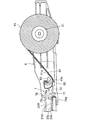
図3に、可動パネル31及び固定パネル32を省略したサンルーフ装置100であって、ロールシェード装置4が展開状態にあるときの斜視図を示す。図4に、可動パネル31及び固定パネル32を省略したサンルーフ装置100であって、ロールシェード装置4が巻取状態にあるときの斜視図を示す。   FIG. 3 is a perspective view of the sunroof device 100 in which the movable panel 31 and the fixed panel 32 are omitted, and the roll shade device 4 is in an unfolded state. FIG. 4 is a perspective view of the sunroof device 100 in which the movable panel 31 and the fixed panel 32 are omitted, and the roll shade device 4 is in a winding state.

フレーム2は、概ね車幅方向に延びる前側フレーム21と前後方向に延びる左側及び右側ガイドレール22L,22Rを有している。左側ガイドレール22L及び右側ガイドレール22Rは、アルミニウム合金製である。左側ガイドレール22Lと右側ガイドレール22Rとは、左右対称な構成をしている。左側及び右側ガイドレール22L,22Rは、左右を区別しない場合には、単に「ガイドレール22」と称することがある。   The frame 2 has a front frame 21 extending in the vehicle width direction and left and right guide rails 22L and 22R extending in the front-rear direction. The left guide rail 22L and the right guide rail 22R are made of an aluminum alloy. The left guide rail 22L and the right guide rail 22R have a symmetrical configuration. The left and right guide rails 22L and 22R may be simply referred to as “guide rails 22” when they are not distinguished from each other.

前側フレーム21、左側ガイドレール22L及び右側ガイドレール22Rには、複数のプッシュプルケーブル12が敷設されている(図1に図示)。プッシュプルケーブル12は、外周面にギヤ部が形成されたギヤードケーブルである。前側フレーム21には、プッシュプルケーブル12を駆動する駆動モータ13が取り付けられている。プッシュプルケーブル12は、駆動モータ13と噛合している。   A plurality of push-pull cables 12 are laid on the front frame 21, the left guide rail 22L, and the right guide rail 22R (shown in FIG. 1). The push-pull cable 12 is a geared cable having a gear portion formed on the outer peripheral surface. A drive motor 13 that drives the push-pull cable 12 is attached to the front frame 21. The push-pull cable 12 is meshed with the drive motor 13.

可動パネル31は、左右の連結部材(図示省略)を介して左側ガイドレール22L及び右側ガイドレール22Rにスライド可能に連結されている。各連結部材は、ガイドレール22に設けられ、プッシュプルケーブル12により駆動されるスライダ(図示省略)と係合している。スライダがプッシュプルケーブル12を介して駆動されることによって、連結部材がガイドレール22に沿って摺動したり、連結部材が上下に傾動したりする。それにより、可動パネル31が前後にスライドしたり、上下に傾動したりする。   The movable panel 31 is slidably connected to the left guide rail 22L and the right guide rail 22R via left and right connecting members (not shown). Each connecting member is provided on the guide rail 22 and is engaged with a slider (not shown) driven by the push-pull cable 12. When the slider is driven via the push-pull cable 12, the connecting member slides along the guide rail 22 or the connecting member tilts up and down. Thereby, the movable panel 31 slides back and forth or tilts up and down.

ロールシェード装置4は、可動パネル31及び固定パネル32の下方に設けられている。ロールシェード装置4は、詳しくは後述するが、遮光シート41が巻取りローラ5に巻き取り可能に構成されている。図3に示すように、遮光シート41が巻取りローラ5から引き出された展開状態であって且つ最も引き出された完全展開状態においては、遮光シート41は可動パネル31及び固定パネル32を遮光した状態、即ち、車外から可動パネル31及び固定パネル32を透過して車内へ進入してきた光を遮光する状態となる。一方、図4に示すように、遮光シート41が巻取りローラ5に巻き取られた巻取状態では、遮光シート41は、可動パネル31及び固定パネル32を開放した状態、即ち、車外から可動パネル31及び固定パネル32を透過して車内へ進入してきた光を遮らない状態となる。   The roll shade device 4 is provided below the movable panel 31 and the fixed panel 32. As will be described in detail later, the roll shade device 4 is configured such that the light shielding sheet 41 can be wound around the winding roller 5. As shown in FIG. 3, in the unfolded state where the light shielding sheet 41 is pulled out from the winding roller 5 and in the fully unfolded state where the light shielding sheet 41 is pulled out most, the light shielding sheet 41 shields the movable panel 31 and the fixed panel 32 from light. That is, the light that has entered the vehicle through the movable panel 31 and the fixed panel 32 from the outside of the vehicle is blocked. On the other hand, as shown in FIG. 4, in the winding state in which the light shielding sheet 41 is wound around the winding roller 5, the light shielding sheet 41 is in a state in which the movable panel 31 and the fixed panel 32 are opened, that is, from the outside of the vehicle. It will be in the state which does not block the light which permeate | transmitted 31 and the fixed panel 32, and entered into the vehicle.

<ロールシェード装置の概略構成>
以下に、ロールシェード装置4の構成について詳細に説明する。図5に、外側から見たロールシェード装置4の斜視図を示す。図6に、内側から見たロールシェード装置4の斜視図を示す。尚、図6では、遮光シート41、巻取りローラ5及び押え部材55の図示を省略している。
<Schematic configuration of roll shade device>
Below, the structure of the roll shade apparatus 4 is demonstrated in detail. In FIG. 5, the perspective view of the roll shade apparatus 4 seen from the outer side is shown. In FIG. 6, the perspective view of the roll shade apparatus 4 seen from the inner side is shown. In FIG. 6, illustration of the light shielding sheet 41, the winding roller 5, and the pressing member 55 is omitted.

ロールシェード装置4は、電動式ロールシェード装置である。ロールシェード装置4は、遮光シート41と、遮光シート41を巻取り可能に構成された巻取りローラ5と、巻取りローラ5を支持する2つの支持ブロック6と、支持ブロック6に設けられ、巻取りローラ5から引き出される遮光シート41をガイドレール22へ案内するガイド部7と、遮光シート41の浮き上がりを低減するように該遮光シート41を案内する押え部材55とを有している。また、左側ガイドレール22Lと右側ガイドレール22Rは、ロールシェード装置4の一部を構成する。左側ガイドレール22Lと右側ガイドレール22Rは、遮光シート41を案内する機能を有する。遮光シート41は、巻取りローラ5から引き出された状態においては可動パネル31及び固定パネル32の下方に位置し、可動パネル31及び固定パネル32を介して車室内へ進入する光を遮光する。   The roll shade device 4 is an electric roll shade device. The roll shade device 4 is provided in the light shielding sheet 41, a winding roller 5 configured to be able to wind the light shielding sheet 41, two support blocks 6 that support the winding roller 5, and the support block 6. A guide portion 7 that guides the light shielding sheet 41 drawn out from the take-up roller 5 to the guide rail 22 and a pressing member 55 that guides the light shielding sheet 41 so as to reduce the lifting of the light shielding sheet 41 are provided. Further, the left guide rail 22L and the right guide rail 22R constitute a part of the roll shade device 4. The left guide rail 22L and the right guide rail 22R have a function of guiding the light shielding sheet 41. The light shielding sheet 41 is positioned below the movable panel 31 and the fixed panel 32 in a state where the light shielding sheet 41 is drawn out from the winding roller 5, and shields light entering the vehicle interior via the movable panel 31 and the fixed panel 32.

2つの支持ブロック6はそれぞれ、左側ガイドレール22Lと右側ガイドレール22Rの後端部に取り付けられている。支持ブロック6は、ガイドレール22へ取り付けられる取付部61と、巻取りローラ5のシャフト51を支持する支持部62と、押え部材55を支持する支持ピン63と前記ガイド部7とを有している。支持ブロック6は、金属プレートと樹脂とが一体成形されたインサート成形品である。   The two support blocks 6 are respectively attached to the rear end portions of the left guide rail 22L and the right guide rail 22R. The support block 6 includes an attachment portion 61 attached to the guide rail 22, a support portion 62 that supports the shaft 51 of the winding roller 5, a support pin 63 that supports the pressing member 55, and the guide portion 7. Yes. The support block 6 is an insert molded product in which a metal plate and a resin are integrally molded.

取付部61は、概ね板状に形成され、ガイドレール22の後端に挿入可能な形状をしている。具体的には、ガイドレール22には、後述するシート通路部23よりも車幅方向外側に、前記可動パネル31の連結部材及びスライダが移動する通路24が形成されている。取付部61は、通路24の後端部に挿入される。取付部61には、通路24を区画する壁部にタッピングネジ64により締結される。   The attachment portion 61 is generally formed in a plate shape and can be inserted into the rear end of the guide rail 22. Specifically, the guide rail 22 is formed with a passage 24 in which the connecting member and the slider of the movable panel 31 move on the outer side in the vehicle width direction from a seat passage portion 23 described later. The attachment portion 61 is inserted into the rear end portion of the passage 24. The attachment portion 61 is fastened to a wall portion that defines the passage 24 by a tapping screw 64.

支持部62は、金属プレートによって形成されている。支持部62には、挿通孔62aが形成されている。挿通孔62aは、長穴状の開口である。図5に示すように、巻取りローラ5のシャフト51の端部の断面は、扁平な形状をしており、挿通孔62aに挿通される。挿通孔62a及びシャフト51の端部が真円でないことにより、支持部62は、シャフト51を回転不能に支持する。   The support part 62 is formed of a metal plate. An insertion hole 62 a is formed in the support portion 62. The insertion hole 62a is a long hole-shaped opening. As shown in FIG. 5, the cross section of the end portion of the shaft 51 of the winding roller 5 has a flat shape and is inserted through the insertion hole 62a. Since the insertion hole 62a and the end portion of the shaft 51 are not perfect circles, the support portion 62 supports the shaft 51 in a non-rotatable manner.

支持ピン63は、支持部62よりも前方であって且つガイド部23の後端よりも後方に位置している。支持ピン63は、車幅方向内側に突出しており、押え部材55の端部に係合する。それにより、支持ピン63は、押え部材55を支持している。   The support pin 63 is located in front of the support part 62 and in the rear of the rear end of the guide part 23. The support pin 63 protrudes inward in the vehicle width direction and engages with the end portion of the presser member 55. Thereby, the support pin 63 supports the presser member 55.

支持ブロック6のうち支持ピン63よりも前方の部分には、ガイド部7が設けられている。ガイド部7の詳細な構成については後述する。   A guide portion 7 is provided in a portion of the support block 6 in front of the support pin 63. The detailed configuration of the guide unit 7 will be described later.

巻取りローラ5は、シャフト51と、ローラ本体52と、ローラ本体52に内蔵された付勢機構(図示省略)とを有している。巻取りローラ5は、車幅方向に延びる状態で、左側ガイドレール22Lと右側ガイドレール22Rの後端部に支持ブロック6を介して取り付けられている。シャフト51の両端部は、ローラ本体52の両端部から外側に突出しており、支持ブロック6に回転不能に取り付けられている。ローラ本体52には、遮光シート41が連結されている。ローラ本体52は、付勢機構(図示省略)によってシャフト51周りの一方向に付勢されている。そのため、遮光シート41は、付勢機構の付勢力によりローラ本体52に巻き取られるように構成されている。   The winding roller 5 includes a shaft 51, a roller main body 52, and an urging mechanism (not shown) built in the roller main body 52. The winding roller 5 is attached to the rear end portions of the left guide rail 22L and the right guide rail 22R via the support block 6 while extending in the vehicle width direction. Both end portions of the shaft 51 protrude outward from both end portions of the roller body 52 and are attached to the support block 6 so as not to rotate. A light shielding sheet 41 is connected to the roller body 52. The roller body 52 is urged in one direction around the shaft 51 by an urging mechanism (not shown). Therefore, the light shielding sheet 41 is configured to be wound around the roller body 52 by the urging force of the urging mechanism.

遮光シート41は、遮光性を有する布製シートである。遮光シート41は、実質的に方形をしている。遮光シート41の後端縁は、ローラ本体52に連結されている。遮光シート41の前端縁には、図3,4に示すように、該前端縁に沿って車幅方向に延びるガーニッシュ42が取り付けられている。このガーニッシュ42の車幅方向の両端部には、スライダ42aが設けられている。スライダ42aは、左側ガイドレール22L及び右側ガイドレール22Rに案内され、プッシュプルケーブル12に連結されている。つまり、駆動モータ13によりプッシュプルケーブル12が駆動されると、ガーニッシュ42がガイドレール22に沿って前後に移動する。遮光シート41は、ガーニッシュ42が前方へ移動するときには、ローラ本体52に巻き取られた状態から付勢機構の付勢力に抗して引き出される一方、ガーニッシュ42が後方へ移動するときには、付勢機構の付勢力によりローラ本体52に巻き取られる。スライダ42aは、摺動部材の一例で或る。   The light shielding sheet 41 is a cloth sheet having a light shielding property. The light shielding sheet 41 is substantially rectangular. The rear edge of the light shielding sheet 41 is connected to the roller body 52. As shown in FIGS. 3 and 4, a garnish 42 extending in the vehicle width direction along the front end edge is attached to the front end edge of the light shielding sheet 41. Sliders 42 a are provided at both ends of the garnish 42 in the vehicle width direction. The slider 42a is guided by the left guide rail 22L and the right guide rail 22R, and is connected to the push-pull cable 12. That is, when the push-pull cable 12 is driven by the drive motor 13, the garnish 42 moves back and forth along the guide rail 22. When the garnish 42 moves forward, the light shielding sheet 41 is pulled out from the state wound around the roller body 52 against the urging force of the urging mechanism, while when the garnish 42 moves rearward, the urging mechanism The roller body 52 is wound by the urging force. The slider 42a is an example of a sliding member.

ガイドレール22の車幅方向内側には、詳しくは後述するが、前後方向に延びるシート通路部23が形成されている。遮光シート41の車幅方向両側の、即ち、左右の側端縁部(以下、単に「側端縁部」という)はそれぞれ、左側及び右側ガイドレール22L,22Rのシート通路部23,23に嵌まっており、遮光シート41が前後に移動する際に該左側及び右側ガイドレール22L,22Rによって案内される。   As will be described in detail later, a seat passage portion 23 extending in the front-rear direction is formed on the inner side of the guide rail 22 in the vehicle width direction. The left and right side edge portions (hereinafter simply referred to as “side edge portions”) on both sides in the vehicle width direction of the light shielding sheet 41 are fitted in the sheet passage portions 23 and 23 of the left and right guide rails 22L and 22R, respectively. When the light shielding sheet 41 moves back and forth, it is guided by the left and right guide rails 22L and 22R.

押え部材55は、巻取りローラ5から引き出される遮光シート41の一方の面を押さえて該遮光シート41の高さ位置を調整する。押え部材55は、巻取りローラ5の前方において車幅方向に延びる状態で支持ブロック6に支持されている。押え部材55は、シート通路部23と略同じ高さに位置している。押え部材55は、アルミニウム合金製である。巻取りローラ5のシャフト51は、シート通路部23よりも高い位置に配置され且つ、ロール状に巻き取られた遮光シート41は、巻取りローラ5の上方を前方へ回り込んで前方へ引き出される。そのため、巻取りローラ5から引き出される遮光シート41は、シート通路部23よりも高い位置から前方且つ斜め下の方向に延びてシート通路部23に進入している。このとき、遮光シート41は、押え部材55の下方を通ることによって押え部材55により押さえ込まれてシート通路部23と略同じ高さに位置している。押え部材55が無ければ、遮光シート41はシート通路部23の後端から巻取りローラ5に向かって上方に反り上がった状態になってしまい、車室内からの見栄えが悪くなってしまう。それに対し、遮光シート41のうち巻取りローラ5から引き出された直後の部分を押え部材55で下方へ押さえつけることによって、遮光シート41のうち巻取りローラ5の近傍部分の浮き上がりを低減して、遮光シート41の車室内からの美感を向上させている。さらに、シート通路部23に進入する直前の遮光シート41の高さをシート通路部23の高さに近づけることができ、これにより遮光シート41のシート通路部23への円滑な導入を実現している。   The pressing member 55 adjusts the height position of the light shielding sheet 41 by pressing one surface of the light shielding sheet 41 pulled out from the winding roller 5. The pressing member 55 is supported by the support block 6 so as to extend in the vehicle width direction in front of the winding roller 5. The pressing member 55 is located at substantially the same height as the sheet passage portion 23. The holding member 55 is made of an aluminum alloy. The shaft 51 of the take-up roller 5 is disposed at a position higher than the sheet passage portion 23, and the light-shielding sheet 41 wound up in a roll shape moves forward over the take-up roller 5 and is drawn forward. . Therefore, the light shielding sheet 41 drawn out from the winding roller 5 extends forward and obliquely downward from a position higher than the sheet path portion 23 and enters the sheet path portion 23. At this time, the light shielding sheet 41 passes through the lower part of the pressing member 55 and is pressed by the pressing member 55 and is positioned at substantially the same height as the sheet path portion 23. Without the pressing member 55, the light shielding sheet 41 is warped upward from the rear end of the sheet passage portion 23 toward the winding roller 5, and the appearance from the passenger compartment is deteriorated. On the other hand, the portion immediately after being pulled out of the winding roller 5 in the light shielding sheet 41 is pressed downward by the pressing member 55 to reduce the floating of the portion in the vicinity of the winding roller 5 in the light shielding sheet 41 so as to block the light. The beauty of the seat 41 from the passenger compartment is improved. Further, the height of the light shielding sheet 41 immediately before entering the sheet passage portion 23 can be made close to the height of the sheet passage portion 23, thereby realizing a smooth introduction of the light shielding sheet 41 into the sheet passage portion 23. Yes.

<遮光シートのガイドレールでの案内構造>
続いて、シート通路部23による遮光シート41の案内構造について詳しく説明する。図7に、遮光シート41の平面図を示す。図8に、シート通路部23及び遮光シート41の断面図を示す。
<Guide structure with light guide sheet guide rail>
Next, the guide structure of the light shielding sheet 41 by the sheet passage portion 23 will be described in detail. FIG. 7 shows a plan view of the light shielding sheet 41. FIG. 8 shows a cross-sectional view of the sheet passage portion 23 and the light shielding sheet 41.

遮光シート41は、図7に示すように、方形のシート本体41aと、シート本体41aの車幅方向両側、即ち、左右の側端縁部において側端縁部に沿って前後方向に延びる係合帯43とを有する。係合帯43は、シート本体41aとは別の部材で形成されている。係合帯43は、縫合部41bを介してシート本体41aに連結されている。縫合部41bは、係合帯43の比較的車幅方向外側に設けられている。例えば、係合帯43は、樹脂で形成されている。ただし、これに限られず、係合帯43をゴム等の弾性体で形成してもよい。あるいは、シート本体41aの側端縁部を折り返して係合帯43を形成してもよい。つまり、係合帯43をシート本体41aと同じ部材で形成してもよい。   As shown in FIG. 7, the light shielding sheet 41 is a rectangular sheet main body 41 a and an engagement extending in the front-rear direction along the side edge at both sides in the vehicle width direction of the sheet main body 41 a, that is, at the left and right side edges. And a belt 43. The engagement band 43 is formed of a member different from the seat body 41a. The engagement band 43 is connected to the sheet main body 41a via the stitching portion 41b. The stitching portion 41b is provided on the relatively outer side in the vehicle width direction of the engagement band 43. For example, the engagement band 43 is made of resin. However, the present invention is not limited to this, and the engagement band 43 may be formed of an elastic body such as rubber. Alternatively, the engagement band 43 may be formed by folding back the side edge of the sheet body 41a. That is, the engagement band 43 may be formed of the same member as the seat body 41a.

係合帯43は、少なくとも車幅方向内側の端縁部がシート本体41aと離反して、シート本体41aとの間に隙間を有するように構成されている。縫合部41bが係合帯43の比較的車幅方向外側に設けられているので、係合帯43の車幅方向内側の端縁部とシート本体41aとの間に隙間が形成されやすくなっている。   The engagement band 43 is configured such that at least an end edge portion on the inner side in the vehicle width direction is separated from the seat body 41a and a gap is formed between the engagement band 43 and the seat body 41a. Since the stitching portion 41b is provided on the outer side in the vehicle width direction of the engagement band 43, a gap is easily formed between the end edge portion on the inner side in the vehicle width direction of the engagement band 43 and the seat body 41a. Yes.

ただし、係合帯43のうち、ガイドレール22内に進入する際の先頭となる先端部43aは、シート本体41aに縫合されていない。つまり、係合帯43の先端部43aは、シート本体41aに連結されておらず、シート本体41aに拘束されていない。   However, the front end portion 43a of the engagement band 43 when entering the guide rail 22 is not stitched to the seat body 41a. That is, the distal end portion 43a of the engagement band 43 is not connected to the seat body 41a and is not restrained by the seat body 41a.

また、係合帯43の先端部43aは、部分的にシート本体41aからはみ出している。具体的には、シート本体41aの前端縁と側端縁とで形成される隅部は、斜めにカットされている。係合帯43の先端部43aは、シート本体41aの斜めの端縁よりも前方にはみ出している。尚、係合帯43の先端部43aは、シート本体41aからはみ出す部分だけでなく、シート本体41aと重なり合う部分もシート本体41aと縫合されていない。つまり、シート本体41aの前端部と係合帯43とは連結されていない。   Further, the distal end portion 43a of the engagement band 43 partially protrudes from the seat body 41a. Specifically, the corner formed by the front edge and the side edge of the sheet main body 41a is cut obliquely. The distal end portion 43a of the engagement band 43 protrudes forward from the oblique end edge of the seat body 41a. It should be noted that the distal end portion 43a of the engagement band 43 is not sewn to the sheet main body 41a in addition to the portion protruding from the sheet main body 41a. That is, the front end portion of the seat body 41a and the engagement band 43 are not connected.

さらに、係合帯43の先端縁43bは、前後方向に対して垂直ではなく(即ち、車幅方向と平行ではなく)、前後方向に対して傾斜(即ち、車幅方向に対して傾斜)している。具体的には、係合帯43の先端縁43bは、車幅方向外側ほど前側、即ち、先頭側に位置するように傾斜している。   Further, the front end edge 43b of the engagement band 43 is not perpendicular to the front-rear direction (that is, not parallel to the vehicle width direction) and is inclined relative to the front-rear direction (ie, inclined relative to the vehicle width direction). ing. Specifically, the front end edge 43b of the engagement band 43 is inclined so as to be located on the front side, that is, on the leading side, as it goes outward in the vehicle width direction.

尚、係合帯43の先端縁43bには、遮光シート41を巻取りローラ5に巻き取る際にスライダ42aが接触し、係合帯43はスライダ42aにより巻取りローラ5の方へ押される。遮光シート41は、基本的には、巻取りローラ5の付勢力により巻き取られる。遮光シート41の先端部に設けられたガーニッシュ42にはスライダ42aが連結され、スライダ42aにはプッシュプルケーブル12が連結されている。そのため、遮光シート41の巻取り時には、巻取りローラ5による巻取りを阻害しないように、スライダ42aが後方へ、即ち、巻取りローラ5の方へ駆動される。このとき、スライダ42aは、巻取りローラ5による遮光シート41の巻取りを促進させる程度の力で係合帯43の先端縁43bを押すように駆動される。その結果、遮光シート41を、巻取りローラ5の付勢力だけでなく、スライダ42aによる押圧力wお利用して巻き取ることができる。   The slider 42a contacts the tip edge 43b of the engagement band 43 when the light shielding sheet 41 is wound around the winding roller 5, and the engagement band 43 is pushed toward the winding roller 5 by the slider 42a. The light shielding sheet 41 is basically wound by the urging force of the winding roller 5. A slider 42a is connected to the garnish 42 provided at the tip of the light shielding sheet 41, and the push-pull cable 12 is connected to the slider 42a. Therefore, when the light shielding sheet 41 is wound, the slider 42 a is driven backward, that is, toward the winding roller 5 so as not to hinder winding by the winding roller 5. At this time, the slider 42 a is driven so as to push the leading edge 43 b of the engagement band 43 with a force that promotes the winding of the light shielding sheet 41 by the winding roller 5. As a result, the light shielding sheet 41 can be wound using not only the urging force of the winding roller 5 but also the pressing force w by the slider 42a.

次に、シート通路部23の構成について説明する。シート通路部23は、図8に示すように、遮光シート41の側端縁部よりも車幅方向外側に位置し且つ上下方向に立ち上がった状態の縦壁部23aと、該縦壁部23aの上端縁から車幅方向内側に延びる上壁部23bと、縦壁部23aの下端部から車幅方向内側に延びる下壁部23cと、該下壁部23cにおける車幅方向内側の端縁から上方に延びる係合壁部23dとを有している。縦壁部23a、上壁部23b、下壁部23c及び係合壁部23dは何れも前後方向に延びている。下壁部23cは、段差を有し、車幅方向内側部分の方が車幅方向外側部分よりも低くなっている。係合壁部23dは、上側の部分ほど車幅方向外側に位置するように傾斜している。   Next, the configuration of the seat passage portion 23 will be described. As shown in FIG. 8, the sheet passage portion 23 is located on the outer side in the vehicle width direction with respect to the side edge portion of the light shielding sheet 41 and rises up and down, and the vertical wall portion 23 a An upper wall portion 23b extending inward in the vehicle width direction from the upper end edge, a lower wall portion 23c extending inward in the vehicle width direction from the lower end portion of the vertical wall portion 23a, and an upper edge from the inner edge in the vehicle width direction of the lower wall portion 23c And an engaging wall portion 23d extending in the direction. The vertical wall portion 23a, the upper wall portion 23b, the lower wall portion 23c, and the engaging wall portion 23d all extend in the front-rear direction. The lower wall portion 23c has a step, and the inner portion in the vehicle width direction is lower than the outer portion in the vehicle width direction. The engaging wall portion 23d is inclined so that the upper portion is positioned on the outer side in the vehicle width direction.

下壁部23cは、上壁部23bよりも車幅方向内側まで延びている。つまり、係合壁部23dは、上壁部23bの車幅方向内側の端縁よりも車幅方向内側に位置している。そのため、上壁部23bの車幅方向内側の端縁と係合壁部23dの上端縁とによって前後方向に延びるスリット23eが形成され、シート通路部23はスリット23eを介して開口している。   The lower wall portion 23c extends to the inner side in the vehicle width direction than the upper wall portion 23b. That is, the engaging wall portion 23d is located on the inner side in the vehicle width direction with respect to the inner edge in the vehicle width direction of the upper wall portion 23b. Therefore, a slit 23e extending in the front-rear direction is formed by the end of the upper wall portion 23b on the inner side in the vehicle width direction and the upper end edge of the engagement wall portion 23d, and the seat passage portion 23 opens through the slit 23e.

シート本体41aの側端縁部及び係合帯43は、スリット23eを介してシート通路部23内に入り込んでいる。このとき、上壁部23bは、シート本体41aの側端縁部の上面と対向し、下壁部23cは、係合帯43の下面と対向している。係合壁部23dは、係合帯43よりも車幅方向内側で且つシート本体41aの下方に位置している。   The side edge portion of the sheet main body 41a and the engagement band 43 enter the sheet passage portion 23 through the slit 23e. At this time, the upper wall portion 23 b faces the upper surface of the side edge portion of the sheet main body 41 a, and the lower wall portion 23 c faces the lower surface of the engagement band 43. The engagement wall portion 23d is located on the inner side in the vehicle width direction than the engagement band 43 and below the seat body 41a.

このように、シート通路部23は、シート本体41aの側端縁部及び係合帯43を共に収容して前後方向に案内する。シート本体41aは、通常は係合壁部23dの上端及び上壁部23bに摺接しながら、前後方向に案内される。係合壁部23dは、係合帯43よりも車幅方向内側に位置して該係合帯43と係合する。このように、シート本体41aに係合帯43を設け且つシート通路部23に係合壁部23dを設けることによって、シート本体41aのシート通路部23からの離脱、即ち、遮光シート41がシート通路部23から抜け出ることを防止している。遮光シート41は可撓性を有しているので、例えば、遮光シート41の車幅方向中央の部分が自重により下方に撓んだときには、遮光シート41の左右の側端縁部は車幅方向内側へ移動する。また、遮光シート41が左右の何れかに移動した場合にも、一方の側端縁部は車幅方向内側へ移動する。しかし、係合壁部23dが係合帯43よりも車幅方向内側に位置するので、係合帯43が係合壁部23dに引っ掛かって、遮光シート41の車幅方向内側への移動が阻止される。これにより、遮光シート41とシート通路部23との係合が維持される。   Thus, the seat passage portion 23 accommodates both the side edge portion of the seat body 41a and the engagement band 43 and guides them in the front-rear direction. The seat body 41a is normally guided in the front-rear direction while being in sliding contact with the upper end of the engaging wall portion 23d and the upper wall portion 23b. The engagement wall portion 23 d is located on the inner side in the vehicle width direction with respect to the engagement band 43 and engages with the engagement band 43. Thus, by providing the engagement band 43 in the sheet main body 41a and the engagement wall 23d in the sheet passage portion 23, the sheet main body 41a is detached from the sheet passage portion 23, that is, the light shielding sheet 41 is moved to the sheet passage. It is prevented from coming out of the portion 23. Since the light shielding sheet 41 has flexibility, for example, when the central portion of the light shielding sheet 41 in the vehicle width direction is bent downward by its own weight, the left and right side edge portions of the light shielding sheet 41 are in the vehicle width direction. Move inward. Further, even when the light shielding sheet 41 moves to the left or right, one side edge portion moves inward in the vehicle width direction. However, since the engagement wall portion 23d is located on the inner side in the vehicle width direction than the engagement band 43, the engagement band 43 is caught by the engagement wall portion 23d and the movement of the light shielding sheet 41 to the inner side in the vehicle width direction is prevented. Is done. Thereby, the engagement between the light shielding sheet 41 and the sheet passage portion 23 is maintained.

<遮光シートのガイドレールへの案内構造>
このように構成された遮光シート41は、巻取りローラ5に巻き取られるときには、シート通路部23から抜け出て、シート通路部23には案内されていない。遮光シート41が巻取りローラ5に完全に巻き取られた状態(巻取状態)においては、遮光シート41の全ての部分が、シート通路部23から抜け出た状態となる。ここで、遮光シート41が巻取りローラ5に巻き取られた状態においては、シート本体41aと係合帯43とが互いに重なり合っている。そのため、巻取状態から遮光シート41を引き出す際には、遮光シート41をシート通路部23へ案内して、シート通路部23内へ適切に進入させる必要がある。具体的には、シート本体41aの側端縁部がシート通路23内に収容され、残りの部分がスリット23eを介してシート通路23の外部に出た状態となり、係合帯43の全てがシート通路23内に収容されるようにする必要がある。
<Guide structure of light shielding sheet to guide rail>
When the light shielding sheet 41 configured in this way is wound around the winding roller 5, the light blocking sheet 41 is pulled out of the sheet path portion 23 and is not guided to the sheet path portion 23. In a state where the light shielding sheet 41 is completely wound around the winding roller 5 (winding state), all the portions of the light shielding sheet 41 come out of the sheet path portion 23. Here, in a state where the light shielding sheet 41 is wound around the winding roller 5, the sheet main body 41 a and the engagement band 43 overlap each other. Therefore, when the light shielding sheet 41 is pulled out from the winding state, it is necessary to guide the light shielding sheet 41 to the sheet path portion 23 and appropriately enter the sheet path portion 23. Specifically, the side edge portion of the sheet main body 41a is accommodated in the sheet passage 23, and the remaining portion protrudes to the outside of the sheet passage 23 through the slit 23e, and the entire engagement band 43 is seated. It is necessary to be accommodated in the passage 23.

支持ブロック6には、巻取りローラ5から引き出される遮光シート41をガイドレール22内へ適切に進入させるガイド部7が設けられている。ガイド部7は、図6に示すように、ガイドレール22の後端縁に設けられた進入口23fから、遮光シート41をシート通路部23内へ進入させる。図9に、図6におけるIX−IX線におけるガイドレール22の断面図を示す。図10に、ガイド部7を中心とする、シェード装置4の平面図を示す。図11に、内壁72を水平面で切断したガイド片71を下方から見た図を示す。   The support block 6 is provided with a guide portion 7 that allows the light shielding sheet 41 drawn out from the take-up roller 5 to appropriately enter the guide rail 22. As shown in FIG. 6, the guide portion 7 causes the light shielding sheet 41 to enter the sheet passage portion 23 from an entrance 23 f provided at the rear end edge of the guide rail 22. FIG. 9 is a cross-sectional view of the guide rail 22 taken along the line IX-IX in FIG. In FIG. 10, the top view of the shade apparatus 4 centering on the guide part 7 is shown. In FIG. 11, the figure which looked at the guide piece 71 which cut | disconnected the inner wall 72 with the horizontal surface from the downward | lower direction is shown.

ガイド部7は、図6に示すように、遮光シート41がガイドレール22内に進入する前に係合帯43をシート本体41aから離反させるガイド片71と、ガイド片71よりもガイドレール22側に設けられ、遮光シート41を進入口23fへ案内するガイド壁76とを有する。   As shown in FIG. 6, the guide portion 7 includes a guide piece 71 that separates the engagement band 43 from the sheet main body 41 a before the light shielding sheet 41 enters the guide rail 22, and the guide rail 22 side from the guide piece 71. And a guide wall 76 for guiding the light shielding sheet 41 to the entrance 23f.

ガイド片71は、支持ブロック6の水平壁65に設けられている。ガイド片71は、水平壁65から上方に延びる内壁72と、該内壁72に連結された分離壁73とを有する。   The guide piece 71 is provided on the horizontal wall 65 of the support block 6. The guide piece 71 has an inner wall 72 extending upward from the horizontal wall 65 and a separation wall 73 connected to the inner wall 72.

内壁72は、係合帯43を案内して、係合帯43の車幅方向位置を規定する。具体的には、内壁72のうち車幅方向外側を向く面(以下、「外側面」という)72aが係合帯43を外側面72aよりも車幅方向外側を通過するように案内する。外壁面72aは、図9に示すように、シート通路部23の係合壁部23dよりも車幅方向外側に位置している。つまり、内壁72は、係合帯43を係合壁部23dよりも車幅方向外側へ案内する。   The inner wall 72 guides the engagement band 43 and defines the position of the engagement band 43 in the vehicle width direction. Specifically, a surface (hereinafter referred to as “outer surface”) 72a facing the outer side in the vehicle width direction of the inner wall 72 guides the engagement band 43 so as to pass the outer side in the vehicle width direction than the outer surface 72a. As shown in FIG. 9, the outer wall surface 72 a is located on the outer side in the vehicle width direction than the engaging wall portion 23 d of the seat passage portion 23. That is, the inner wall 72 guides the engagement band 43 to the outer side in the vehicle width direction than the engagement wall portion 23d.

ここで、外側面72aは、図11に示すように、巻取りローラ5に近づくにつれて車幅方向内側に位置するように、即ち、後側ほど車幅方向内側に位置するように傾斜している。また、内壁72のうち外側面72aと巻取りローラ5の方を向く面72bとで形成される稜部72cは、湾曲面で形成されている。   Here, as shown in FIG. 11, the outer surface 72 a is inclined so as to be positioned inward in the vehicle width direction as it approaches the winding roller 5, that is, to be positioned inward in the vehicle width direction toward the rear side. . Further, a ridge 72 c formed by the outer surface 72 a of the inner wall 72 and the surface 72 b facing the winding roller 5 is formed by a curved surface.

分離壁73は、図6,9に示すように、内壁72から車幅方向外側へ略水平方向に延びている。分離壁73は、遮光シート41をガイド部7により案内する際に、シート本体41aと係合帯43との間に入り込み、遮光シート41と係合帯43とを離反させる。分離壁73は、車幅方向外側ほど薄く且つ、後側ほど薄くなるように形成されている。   As shown in FIGS. 6 and 9, the separation wall 73 extends substantially horizontally from the inner wall 72 outward in the vehicle width direction. When the light shielding sheet 41 is guided by the guide portion 7, the separation wall 73 enters between the sheet main body 41 a and the engagement band 43 to separate the light shielding sheet 41 and the engagement band 43 from each other. The separation wall 73 is formed to be thinner toward the outer side in the vehicle width direction and thinner toward the rear side.

水平壁65には、図6,10に示すように、分離壁73を水平壁65に投影した形状よりも大きな開口部73aが形成されている。開口部73aを設けることによりガイド片71を容易に成形することができる。   As shown in FIGS. 6 and 10, the horizontal wall 65 is formed with an opening 73 a larger than the shape of the separation wall 73 projected onto the horizontal wall 65. By providing the opening 73a, the guide piece 71 can be easily formed.

ガイド壁76は、図6,10に示すように、ガイドレール22の後端縁に隣接している。ガイド壁76には、ガイドレール22の進入口23fと対向するガイド開口部77が設けられている。   The guide wall 76 is adjacent to the rear end edge of the guide rail 22 as shown in FIGS. The guide wall 76 is provided with a guide opening 77 facing the entrance 23 f of the guide rail 22.

ガイド開口部77は、図9に示すように、ガイドレール22の進入口23fに対応した形状をしている。具体的には、ガイド開口部77の開口縁77aは、水平に延びる上部77bと、上部77bに対向する下部77cと、上部77bの車幅方向外側の端部と下部77cの車幅方向外側の端部とを連結する連結部77dとを有する。下部77cは、段差状に形成されており、車幅方向内側の部分が車幅方向外側の部分に比べて下方に下がっている。上部77bの車幅方向内側の端部と下部77cの車幅方向内側の端部とは、連結されていない。すなわち、開口縁77aは、開いた形状をしている。このように構成されたガイド開口部77は、進入口23fよりも小さい。つまり、ガイド開口部77を後方から見たときには、進入口23fの開口縁は見えない。   As shown in FIG. 9, the guide opening 77 has a shape corresponding to the entrance 23 f of the guide rail 22. Specifically, the opening edge 77a of the guide opening 77 includes an upper portion 77b that extends horizontally, a lower portion 77c that opposes the upper portion 77b, an end portion on the outer side in the vehicle width direction of the upper portion 77b, and an outer side in the vehicle width direction of the lower portion 77c. And a connecting portion 77d for connecting the end portions. The lower portion 77c is formed in a stepped shape, and a portion on the inner side in the vehicle width direction is lower than a portion on the outer side in the vehicle width direction. The end portion of the upper portion 77b on the inner side in the vehicle width direction and the end portion of the lower portion 77c on the inner side in the vehicle width direction are not connected. That is, the opening edge 77a has an open shape. The guide opening 77 configured in this manner is smaller than the entrance 23f. That is, when the guide opening 77 is viewed from the rear, the opening edge of the entrance 23f is not visible.

また、ガイド壁76には、図6に示すように、遮光シート41をガイド開口部77へ導く傾斜面76aが設けられている。傾斜面76aは、ガイド壁76の後面(進入口23fと反対側の面)であってガイド開口部77の上方に設けられている。傾斜面76aは、下側の部分ほど前方に位置するように傾斜している。傾斜面76aは、開口縁77aの上部77bにつながっている。   Further, as shown in FIG. 6, the guide wall 76 is provided with an inclined surface 76 a that guides the light shielding sheet 41 to the guide opening 77. The inclined surface 76 a is a rear surface of the guide wall 76 (surface opposite to the entrance 23 f) and is provided above the guide opening 77. The inclined surface 76a is inclined so that the lower part is positioned forward. The inclined surface 76a is connected to the upper portion 77b of the opening edge 77a.

ガイド壁76のガイドレール22側の面には、支持ブロック6をガイドレール22に取り付ける際にガイドレール22に係合する第1係合部76c及び第2係合部76dが設けられている。第1係合部76cは、上壁部23bの上面に係合する。第2係合部76dは、下壁部23cの下面に係合する。   A first engaging portion 76 c and a second engaging portion 76 d that are engaged with the guide rail 22 when the support block 6 is attached to the guide rail 22 are provided on the surface of the guide wall 76 on the guide rail 22 side. The first engaging portion 76c engages with the upper surface of the upper wall portion 23b. The second engaging portion 76d engages with the lower surface of the lower wall portion 23c.

続いて、遮光シート41が巻取状態から引き出されて、ガイドレール22のシート通路部23に進入する際の動作について説明する。図12に、シェード装置4を内側から見た側面図を示す。尚、図12においては、遮光シート41及び巻取りローラ5を前後方向及び上下方向に拡がる平面で切断している。図13に、遮光シート41がガイド片71に係合し始めた状態を示す図を示す。図13(A)は、遮光シート41及びガイド片71を上方から見た図であり、図13(B)は、遮光シート41及びガイド片71を下方から見た図である。図14に、分離壁73がシート本体41aと係合帯43との間に入り込んだ状態の断面図を示す。図15に、遮光シート41がガイド開口部77を介してシート通路部23内に進入した状態を示す図を示す。   Next, an operation when the light shielding sheet 41 is pulled out from the wound state and enters the sheet path portion 23 of the guide rail 22 will be described. In FIG. 12, the side view which looked at the shade apparatus 4 from the inner side is shown. In FIG. 12, the light shielding sheet 41 and the take-up roller 5 are cut along a plane extending in the front-rear direction and the up-down direction. FIG. 13 shows a state in which the light shielding sheet 41 starts to engage with the guide piece 71. FIG. 13A is a view of the light shielding sheet 41 and the guide piece 71 as viewed from above, and FIG. 13B is a view of the light shielding sheet 41 and the guide piece 71 as viewed from below. FIG. 14 is a cross-sectional view showing a state in which the separation wall 73 has entered between the sheet main body 41 a and the engagement band 43. FIG. 15 shows a state in which the light shielding sheet 41 has entered the sheet passage portion 23 through the guide opening 77.

図12に示すように、巻取状態において、遮光シート41は、巻取りローラ5から押え部材55(図12では図示省略)に向かって斜め下に延び、押え部材55に巻き掛けられている。つまり、遮光シート41は、ガイドレール22が延びる方向(即ち、前後方向)に対して斜めに巻取りローラ5から引き出されたあと、押え部材55の位置で屈曲してガイドレール22が延びる方向に進んで、ガイドレール22に進入するように構成されている。遮光シート41は、押え部材55の位置において、係合帯43を外側とし、シート本体41aを内側にして屈曲している。ここで、巻取状態においては、遮光シート41の先端部は、押え部材55の近傍に位置している。このとき、シート本体41aの先端部は、押え部材55に巻き掛けられている一方、係合帯43の先端部43aは、シート本体41aに縫合されていないので、巻取りローラ5と押え部材55との間と同様に、斜め下方に向かって延びている。こうして、係合帯43の先端部43aは、シート本体41aから離反している。係合帯43の先端部43aは、支持ブロック6の水平壁65に接触しており、ガイド片71の分離壁73よりも低い位置に位置している。   As shown in FIG. 12, in the winding state, the light shielding sheet 41 extends obliquely downward from the winding roller 5 toward the pressing member 55 (not shown in FIG. 12) and is wound around the pressing member 55. That is, the light shielding sheet 41 is pulled out from the winding roller 5 obliquely with respect to the direction in which the guide rail 22 extends (that is, the front-rear direction), and then bent at the position of the pressing member 55 in the direction in which the guide rail 22 extends. It is configured to proceed and enter the guide rail 22. The light shielding sheet 41 is bent at the position of the pressing member 55 with the engagement band 43 on the outside and the sheet body 41a on the inside. Here, in the winding state, the front end portion of the light shielding sheet 41 is located in the vicinity of the pressing member 55. At this time, the leading end portion of the sheet main body 41a is wound around the pressing member 55, while the leading end portion 43a of the engagement band 43 is not stitched to the sheet main body 41a. As in between, it extends obliquely downward. Thus, the distal end portion 43a of the engagement band 43 is separated from the sheet main body 41a. The distal end portion 43 a of the engagement band 43 is in contact with the horizontal wall 65 of the support block 6 and is positioned at a position lower than the separation wall 73 of the guide piece 71.

遮光シート41は、この状態から前方へ略水平に引き出される。図13に示すように、シート本体41aは、ガイド片71の分離壁73上に乗り上げる。一方、係合帯43の先端部43aは、分離壁73の下方へ入り込む。こうして、分離壁73がシート本体41aと係合帯43との間に先端側から入り込む。   The light shielding sheet 41 is pulled out substantially horizontally from this state to the front. As shown in FIG. 13, the sheet main body 41 a rides on the separation wall 73 of the guide piece 71. On the other hand, the distal end portion 43 a of the engagement band 43 enters below the separation wall 73. Thus, the separation wall 73 enters between the sheet main body 41a and the engagement band 43 from the front end side.

このように、係合帯43の先端部43aをシート本体41aに連結せず、自由端とすることによって、分離壁73をシート本体41aと係合帯43との間に円滑に入り込ませることができる。また、係合帯43の先端部43aをシート本体41aよりも前方にはみ出させているため、係合帯43をガイド片71に容易に係合させることができる。   As described above, the separation wall 73 can be smoothly inserted between the seat body 41a and the engagement band 43 by connecting the distal end portion 43a of the engagement band 43 to the seat body 41a without being connected to the free end. it can. Further, since the distal end portion 43a of the engagement band 43 protrudes forward from the seat body 41a, the engagement band 43 can be easily engaged with the guide piece 71.

ここで、分離壁73は後ろ側ほど薄く形成されているので、分離壁73に対して後方から向かってくるシート本体41aと係合帯43との間に分離壁73がスムーズに入り込む。   Here, since the separation wall 73 is formed thinner toward the rear side, the separation wall 73 smoothly enters between the sheet main body 41 a and the engagement band 43 coming from the rear with respect to the separation wall 73.

遮光シート41がさらに引き出されると、遮光シート41のうち縫合部41bによりシート本体41aと係合帯43とが連結されている部分がガイド片71に達する。この部分においては、図14に示すように、分離壁73がシート本体41aと係合帯43との間に車幅方向内側から入り込んだ状態となる。これにより、係合帯43の車幅方向内側の端縁部がシート本体41aから離反する。   When the light shielding sheet 41 is further pulled out, a portion of the light shielding sheet 41 where the sheet main body 41 a and the engagement band 43 are connected by the stitching portion 41 b reaches the guide piece 71. In this portion, as shown in FIG. 14, the separation wall 73 enters between the seat body 41 a and the engagement band 43 from the inner side in the vehicle width direction. Thereby, the edge part inside the vehicle width direction of the engagement band 43 separates from the seat main body 41a.

ここで、分離壁73は車幅方向外側ほど薄く形成されているので、係合帯43の車幅方向内側の部分ほどシート本体41aから大きく離反させることができる。それに加えて、係合帯43の車幅方向外側の端部がシート本体41aに連結されているので、分離壁73を車幅方向外側ほど薄く形成することによって、分離壁73をシート本体41aと係合帯43との間にスムーズに進入させることができる。   Here, since the separation wall 73 is formed thinner toward the outer side in the vehicle width direction, the portion on the inner side in the vehicle width direction of the engagement band 43 can be largely separated from the seat body 41a. In addition, since the end of the engagement band 43 on the outer side in the vehicle width direction is connected to the seat body 41a, by forming the separation wall 73 thinner toward the outer side in the vehicle width direction, the separation wall 73 and the seat body 41a are formed. It is possible to smoothly enter between the engagement band 43.

このとき、係合帯43の車幅方向の位置は、ガイド片71の内壁72により規定される。つまり、係合帯43が比較的車幅方向内側に位置するときには、係合帯43は、図13(B),14に示すように、ガイド片71の内壁72に接触する。係合帯43は、内壁72により内壁72よりも車幅方向外側を通過するように案内される。内壁72の外側面72aは後側ほど車幅方向内側に位置するように傾斜しているので、係合帯43は、内壁72の外側面72aに摺接しながら前方へ進むことによって、徐々に車幅方向外側へ案内されていく。係合帯43は、最終的にシート通路部23の係合壁部23dよりも車幅方向外側の位置まで案内される。   At this time, the position of the engagement band 43 in the vehicle width direction is defined by the inner wall 72 of the guide piece 71. That is, when the engagement band 43 is located relatively inward in the vehicle width direction, the engagement band 43 contacts the inner wall 72 of the guide piece 71 as shown in FIGS. The engagement band 43 is guided by the inner wall 72 so as to pass outside of the inner wall 72 in the vehicle width direction. Since the outer side surface 72a of the inner wall 72 is inclined so as to be located on the inner side in the vehicle width direction toward the rear side, the engagement band 43 gradually moves toward the vehicle while moving forward while sliding on the outer side surface 72a of the inner wall 72. Guided outward in the width direction. The engagement band 43 is finally guided to a position outside the engagement wall portion 23d of the seat passage portion 23 in the vehicle width direction.

ここで、内壁72の車幅方向外側且つ後側の稜部72cが湾曲面で形成されているので、係合帯43の前端縁が稜部72cに当接したときには、係合帯43は該稜部72cの湾曲形状に沿って外側面72aへスムーズに案内される。   Here, since the ridge portion 72c on the outer side in the vehicle width direction and the rear side of the inner wall 72 is formed with a curved surface, when the front end edge of the engagement band 43 comes into contact with the ridge portion 72c, the engagement band 43 is It is smoothly guided to the outer surface 72a along the curved shape of the ridge 72c.

さらに、係合帯43の先端縁43bは、車幅方向外側の部分ほど先頭側に位置するように傾斜している。そのため、前方へ引き出される係合帯43の先端縁43bが内壁72に接触したときには、係合帯43は、先端縁43bに沿って車幅方向外側へ案内される。   Furthermore, the front end edge 43b of the engagement band 43 is inclined so that the portion on the outer side in the vehicle width direction is located on the front side. Therefore, when the front end edge 43b of the engagement band 43 drawn out forward contacts the inner wall 72, the engagement band 43 is guided along the front end edge 43b outward in the vehicle width direction.

尚、内壁72の外側面72aから分離壁73の最も車幅方向外側に位置する部分までの車幅方向の距離は、係合帯43の車幅方向内側の端縁から縫合部41bまでの車幅方向への距離よりも短くなっている。これにより、分離壁73が縫合部41bに接触することが防止され、縫合部41bが分離壁73との接触により破損することを防止することができる。   The distance in the vehicle width direction from the outer surface 72a of the inner wall 72 to the portion located on the outermost side in the vehicle width direction of the separation wall 73 is the vehicle distance from the inner edge in the vehicle width direction of the engagement band 43 to the stitching portion 41b. It is shorter than the distance in the width direction. Accordingly, the separation wall 73 can be prevented from coming into contact with the stitching portion 41 b, and the stitching portion 41 b can be prevented from being damaged due to contact with the separation wall 73.

やがて、遮光シート41は、ガイド壁76に到達し、ガイド開口部77に進入する。このとき、シート本体41aは、ガイド壁76に設けられた傾斜面76aによりガイド開口部77まで案内される。ガイド片71により上下に離反していたシート本体41a及び係合帯43は、傾斜面76aによってガイド開口部77に進入可能な程度に接近させられる。   Eventually, the light shielding sheet 41 reaches the guide wall 76 and enters the guide opening 77. At this time, the seat body 41 a is guided to the guide opening 77 by the inclined surface 76 a provided on the guide wall 76. The sheet body 41a and the engagement band 43 that are separated from each other by the guide piece 71 are brought close to the guide opening 77 by the inclined surface 76a.

また、水平壁65にはガイド片71の下方において開口部73aが形成されているため、係合帯43が分離壁73の下方を通過してガイド開口部77に到達するまでの間に、開口部73aの開口縁に接触する可能性がある。ここで、係合帯43の先端縁43bが車幅方向に平行に形成されている場合は、係合帯43の先端縁43bが開口部73aの開口縁に引っ掛かって、遮光シート41をガイドレール22へ円滑に案内できない虞がある。それに対して、係合帯43の先端縁43bは、車幅方向に対して傾斜している。そのため、係合帯43の先端縁43bが開口部73aの開口縁に接触したとしても、係合帯43は、車幅方向へ移動しつつ前進する。その結果、係合帯43の先端縁43bが開口部73aの開口縁に引っ掛かることを防止して、遮光シート41をガイドレール22へ円滑に案内することができる。さらに、先端縁43bは、車幅方向外側の部分ほど先頭側に位置するように傾斜している。そのため、係合帯43は、車幅方向へ逃げる際に車幅方向外側へ移動する。つまり、先端縁43bの傾斜によっても、係合帯43を車幅方向外側へ案内することができる。   In addition, since the opening 73 a is formed below the guide piece 71 in the horizontal wall 65, the opening is made before the engagement band 43 passes below the separation wall 73 and reaches the guide opening 77. There is a possibility of contact with the opening edge of the portion 73a. Here, when the front end edge 43b of the engagement band 43 is formed in parallel to the vehicle width direction, the front end edge 43b of the engagement band 43 is caught by the opening edge of the opening 73a, and the light shielding sheet 41 is moved to the guide rail. There is a possibility that smooth guidance to 22 is not possible. On the other hand, the front end edge 43b of the engagement band 43 is inclined with respect to the vehicle width direction. Therefore, even if the front end edge 43b of the engagement band 43 contacts the opening edge of the opening 73a, the engagement band 43 moves forward while moving in the vehicle width direction. As a result, the front end edge 43b of the engagement band 43 can be prevented from being caught by the opening edge of the opening 73a, and the light shielding sheet 41 can be smoothly guided to the guide rail 22. Further, the tip edge 43b is inclined so that the portion on the outer side in the vehicle width direction is located on the leading side. Therefore, the engagement band 43 moves outward in the vehicle width direction when escaping in the vehicle width direction. That is, the engagement band 43 can be guided outward in the vehicle width direction also by the inclination of the leading edge 43b.

ガイド開口部77はシート通路部23の進入口23fよりも小さいので、ガイド開口部77を通過したシート本体41a及び係合帯43は、進入口23fを介してシート通路部23内にスムーズに進入していく。   Since the guide opening 77 is smaller than the entrance 23f of the seat passage 23, the seat body 41a and the engagement band 43 that have passed through the guide opening 77 smoothly enter the seat passage 23 through the entrance 23f. I will do it.

ここで、図9に示すように、分離壁73の上面73aのうち車幅方向外側の部分は、シート通路部23の上壁部23bよりも低くなっている。さらに、ガイド開口部77の開口縁77aの上部77bは、上壁部23bよりも低く設定されている。一方、分離壁73の上面73aのうち車幅方向内側の部分は、シート通路部23の係合壁部23dよりも高くなっている。それに加えて、ガイド開口部77の開口縁77aの上部77bは、分離壁73の車幅方向外側の部分までしか延びておらず、分離壁73の車幅方向内側の部分や係合壁部23dまでは延びていない。そのため、ガイド片71及びガイド開口部77を通過してシート通路部23内に進入したシート本体41aは、上壁部23bに対応する位置では上壁部23bの下方に入り込み、係合壁部23dに対応する位置では係合壁部23d上に乗り上げた状態となる。   Here, as shown in FIG. 9, a portion of the upper surface 73 a of the separation wall 73 on the outer side in the vehicle width direction is lower than the upper wall portion 23 b of the seat passage portion 23. Furthermore, the upper part 77b of the opening edge 77a of the guide opening 77 is set lower than the upper wall part 23b. On the other hand, a portion on the inner side in the vehicle width direction of the upper surface 73 a of the separation wall 73 is higher than the engagement wall portion 23 d of the seat passage portion 23. In addition, the upper portion 77b of the opening edge 77a of the guide opening 77 extends only to a portion on the outer side in the vehicle width direction of the separation wall 73, and the portion on the inner side in the vehicle width direction of the separation wall 73 and the engaging wall portion 23d. It does not extend to. Therefore, the sheet main body 41a that has entered the sheet passage portion 23 through the guide piece 71 and the guide opening 77 enters the lower portion of the upper wall portion 23b at a position corresponding to the upper wall portion 23b, and engages the engagement wall portion 23d. It will be in the state which got on the engagement wall part 23d in the position corresponding to.

このとき、シート通路部23の縦壁部23a、上壁部23b及び下壁部23cの後端面はガイド壁76に覆われているので、シート本体41aは、ガイドレール22の後端面に接触することなくシート通路部23内に進入する。尚、係合壁部23dの後端面はガイド壁76に覆われておらず露出している。しかし、係合壁部23dに対応する部分のシート本体41aは、分離壁73によって上方に持ち上げられているので、係合壁部23dの後端縁に接触し難くなっている。   At this time, since the rear end surfaces of the vertical wall portion 23a, the upper wall portion 23b, and the lower wall portion 23c of the seat passage portion 23 are covered with the guide wall 76, the seat body 41a contacts the rear end surface of the guide rail 22. It enters the seat passage portion 23 without any change. The rear end surface of the engaging wall portion 23d is not covered with the guide wall 76 and is exposed. However, the portion of the seat body 41a corresponding to the engagement wall 23d is lifted upward by the separation wall 73, so that it is difficult to contact the rear edge of the engagement wall 23d.

また、分離壁73の下面は、係合壁部23dの上端よりも低くなっている。また、内壁72の外側面72aは、係合壁部23dよりも車幅方向外側に位置している。さらに、ガイド開口部77の開口縁77aの下部77cは、シート通路部23の下壁部23cよりも高く設定されている。そのため、ガイド片71及びガイド開口部77を通過してシート通路部23内に進入した係合帯43は、係合壁部23dよりも車幅方向外側であって、係合壁部23dの上端よりも低く位置に収容される。このとき、シート通路部23の縦壁部23a、上壁部23b及び下壁部23cの後端面はガイド壁76に覆われているので、係合帯43は、ガイドレール22の後端面に接触することなくシート通路部23内に進入する。   Further, the lower surface of the separation wall 73 is lower than the upper end of the engagement wall portion 23d. Further, the outer surface 72a of the inner wall 72 is located on the outer side in the vehicle width direction with respect to the engaging wall portion 23d. Further, the lower portion 77 c of the opening edge 77 a of the guide opening 77 is set higher than the lower wall portion 23 c of the seat passage portion 23. Therefore, the engagement band 43 that has passed through the guide piece 71 and the guide opening 77 and entered the seat passage portion 23 is located outside the engagement wall portion 23d in the vehicle width direction, and is located at the upper end of the engagement wall portion 23d. Is housed in a lower position. At this time, since the rear end surfaces of the vertical wall portion 23a, the upper wall portion 23b, and the lower wall portion 23c of the seat passage portion 23 are covered with the guide wall 76, the engagement band 43 contacts the rear end surface of the guide rail 22. The vehicle enters the seat passage portion 23 without doing so.

<まとめ>
前記ロールシェード装置4は、車両のルーフ10に形成された可動パネル31及び固定パネル32に設けられたロールシェード装置である。ロールシェード装置4は、巻取りローラ5と、前記巻取りローラ5に巻き取られた巻取状態では前記可動パネル31及び固定パネル32を開放し、前記巻取状態から引き出された展開状態では前記可動パネル31及び固定パネル32を遮光する遮光シート41と、前記遮光シート41の車幅方向両側に設けられ、該遮光シート41が前記巻取状態と前記展開状態との間で変化する際に該遮光シート41を案内するガイドレール22とを備え、前記遮光シート41は、シート本体41aと、該シート本体41aの車幅方向両側の端縁部において該端縁部に沿って設けられた係合帯43とを有し、前記ガイドレール22は、前記係合帯43よりも車幅方向内側に位置して該係合帯43と係合することによって該遮光シート41の該ガイドレール22からの離脱を防止する係合壁部23dを有し、前記シート本体41aと前記係合帯43とは、互いに重なり合った状態で前記巻取りローラ5に巻き取られ、前記係合帯43のうち、前記ガイドレール22内に進入する際の先頭となる先端部43aは、前記シート本体41aに連結されておらず、該シート本体41aに対して拘束されていない。
<Summary>
The roll shade device 4 is a roll shade device provided on a movable panel 31 and a fixed panel 32 formed on the roof 10 of the vehicle. The roll shade device 4 opens the movable panel 31 and the fixed panel 32 in the winding state of the winding roller 5 and the winding roller 5 and in the unfolded state pulled out from the winding state. A light shielding sheet 41 that shields the movable panel 31 and the fixed panel 32, and provided on both sides of the light shielding sheet 41 in the vehicle width direction, when the light shielding sheet 41 changes between the winding state and the unfolded state. A light guide sheet 22 that guides the light shielding sheet 41. The light shielding sheet 41 includes a seat body 41a and an engagement provided along the edge portions of the sheet body 41a at both side edges in the vehicle width direction. The guide rail 22 is located on the inner side in the vehicle width direction with respect to the engagement band 43 and engages with the engagement band 43 so that the guide rail 2 of the light shielding sheet 41 is provided. The sheet main body 41a and the engagement band 43 are wound around the winding roller 5 in a state of being overlapped with each other. The leading end 43a, which is the head when entering the guide rail 22, is not connected to the seat body 41a and is not restrained by the seat body 41a.

前記の構成によれば、遮光シート41は、巻取状態と展開状態との間で変化する際にはガイドレール22により案内される。このとき、遮光シート41の係合帯43がガイドレール22の係合壁部23dに係合することによって、シート本体41aのガイドレール22からの離脱が防止されている。遮光シート41が巻取りローラ5に巻き取られるときには、シート本体41aと係合帯43とは、互いに重なり合った状態となる。そのため、遮光シート41を巻取りローラ5から引き出す際に、遮光シート41をそのままの状態でガイドレール22内に進入させると、係合帯43が係合壁部23dに適切に係合しない虞がある。より詳しくは、遮光シート41は、側端縁部がガイドレール22に案内され、残りの部分はガイドレール22から出ている。そのため、シート本体41aと係合帯43とを互いに重なり合ったままガイドレール22に進入させると、係合帯43が係合壁部23dに係合せずにガイドレール22からはみ出す虞がある。そうすると、遮光シート41がガイドレール22から簡単に抜け出してしまい、遮光シート41をガイドレール22によって適切に案内できない。   According to the above configuration, the light shielding sheet 41 is guided by the guide rail 22 when changing between the wound state and the unfolded state. At this time, the engagement band 43 of the light shielding sheet 41 is engaged with the engagement wall portion 23d of the guide rail 22, so that the sheet main body 41a is prevented from being detached from the guide rail 22. When the light shielding sheet 41 is taken up by the take-up roller 5, the sheet main body 41a and the engagement band 43 overlap each other. Therefore, when the light shielding sheet 41 is pulled out from the winding roller 5, if the light shielding sheet 41 enters the guide rail 22 as it is, the engagement band 43 may not be properly engaged with the engagement wall portion 23d. is there. More specifically, the side edge of the light shielding sheet 41 is guided by the guide rail 22, and the remaining portion protrudes from the guide rail 22. Therefore, if the seat body 41a and the engagement band 43 are allowed to enter the guide rail 22 while overlapping each other, the engagement band 43 may protrude from the guide rail 22 without being engaged with the engagement wall portion 23d. Then, the light shielding sheet 41 easily comes out of the guide rail 22, and the light shielding sheet 41 cannot be properly guided by the guide rail 22.

係合帯43を係合壁部23dに適切に係合させるためには、係合帯43をシート本体41aから離反させることが好ましい。前記係合帯43の先端部43aは、シート本体41aに連結されておらず、シート本体41aに対して拘束されていないので、該先端部43aは、シート本体41aから容易に離反する。ガイドレール22においては、シート本体41aは、係合壁部23dに乗り上げ、その側端縁部だけがシート通路部23内に入り込んでいる。一方、係合帯43は、係合壁部23dの車幅方向外側において係合壁部23dの上端よりも下方に位置する。つまり、係合壁部23dの近傍においては、シート本体41aと係合帯43とが離反していることが好ましい。前述の如く、係合帯43の先端部43aがシート本体41aに対して非拘束状態である場合には、遮光シート41がガイドレール22に進入するときに、シート本体41aと係合帯43の先端部43aとが容易に離反し、シート本体41aは、係合壁部23dに乗り上げ、係合帯43は、係合壁部23dの車幅方向外側において係合壁部23dの上端よりも低い位置に進入することができる。遮光シート41の先頭においてこの状態を実現することができれば、先頭に続く部分もこの状態を維持してガイドレール22に進入していくことができる。つまり、係合帯43のうち先端部以外のシート本体41aに連結されている部分も、係合壁部23dに係合させることができる。こうして、遮光シート41をガイドレール22内に進入させるときに、遮光シート41の係合帯43をガイドレール22、具体的には、係合壁部23dに容易に係合させることができる。   In order to properly engage the engagement band 43 with the engagement wall portion 23d, it is preferable to separate the engagement band 43 from the seat body 41a. Since the distal end portion 43a of the engagement band 43 is not connected to the seat body 41a and is not restrained with respect to the seat body 41a, the distal end portion 43a is easily separated from the seat body 41a. In the guide rail 22, the seat body 41 a rides on the engaging wall portion 23 d, and only the side edge portion enters the seat passage portion 23. On the other hand, the engagement band 43 is positioned below the upper end of the engagement wall 23d on the outer side in the vehicle width direction of the engagement wall 23d. That is, it is preferable that the seat body 41a and the engagement band 43 are separated in the vicinity of the engagement wall portion 23d. As described above, when the distal end portion 43a of the engagement band 43 is not restrained with respect to the sheet body 41a, when the light shielding sheet 41 enters the guide rail 22, the sheet body 41a and the engagement band 43 The front end portion 43a easily separates, the seat body 41a rides on the engagement wall portion 23d, and the engagement band 43 is lower than the upper end of the engagement wall portion 23d on the outer side in the vehicle width direction of the engagement wall portion 23d. You can enter the position. If this state can be realized at the head of the light shielding sheet 41, the portion following the head can also maintain this state and enter the guide rail 22. That is, the portion of the engagement band 43 that is connected to the sheet main body 41a other than the tip portion can also be engaged with the engagement wall portion 23d. Thus, when the light shielding sheet 41 enters the guide rail 22, the engagement band 43 of the light shielding sheet 41 can be easily engaged with the guide rail 22, specifically, the engagement wall portion 23 d.

さらに、ガイド片71を有する構成においては、係合帯43の先端部43aをシート本体41aから非拘束状態とすることによって、係合帯43の先端部43aをガイド片71に容易に係合させることができる。具体的には、先端部43aをガイド片71の分離壁73の下方へ容易に進入させることができる。   Further, in the configuration having the guide piece 71, the tip end portion 43 a of the engagement band 43 is easily engaged with the guide piece 71 by bringing the tip end portion 43 a of the engagement band 43 from the seat body 41 a into an unconstrained state. be able to. Specifically, the distal end portion 43 a can be easily entered below the separation wall 73 of the guide piece 71.

また、前記係合帯43の先端縁43bは、前記ガイドレール22へ向かって進む方向に対して傾斜している。   Further, the leading edge 43 b of the engagement band 43 is inclined with respect to the direction of traveling toward the guide rail 22.

前記の構成によれば、案内帯43の先端縁43bを傾斜させることによって、案内帯43が前進する際に別の部材に接触したとしても、案内帯43は、先端縁43bの傾斜に沿って、車幅方向に移動しつつ前進する。そのため、案内帯43が別の部材に引っ掛かることを防止することができる。   According to the above configuration, even if the guide band 43 contacts another member when the guide band 43 moves forward by inclining the leading edge 43b of the guide band 43, the guide band 43 follows the inclination of the leading edge 43b. , Move forward in the vehicle width direction. Therefore, the guide band 43 can be prevented from being caught by another member.

具体的には、前記係合帯43の先端縁43bは、車幅方向外側の部分ほど先頭側に位置するように傾斜している。   Specifically, the front end edge 43b of the engagement band 43 is inclined so that the portion on the outer side in the vehicle width direction is located on the front side.

前記の構成によれば、案内帯43の先端縁43bを車幅方向外側の部分ほど先頭側に位置するように傾斜させることによって、先端縁43bが別の部材に接触したときに案内帯43を車幅方向外側へ移動させることができる。この方向は、係合帯43を係合壁部23dに係合させるために案内する方向と一致する。つまり、先端縁43bの傾斜によっても係合帯43を車幅方向外側へ案内することができる。   According to the above-described configuration, the guide band 43 is inclined when the tip edge 43b comes into contact with another member by inclining the tip edge 43b of the guide band 43 so that the outer side in the vehicle width direction is located on the leading side. It can be moved outward in the vehicle width direction. This direction coincides with the direction in which the engagement band 43 is guided to engage with the engagement wall portion 23d. That is, the engagement band 43 can be guided outward in the vehicle width direction also by the inclination of the leading edge 43b.

さらに、前記係合帯43の先端部43aは、前記シート本体41aよりも先頭側にはみ出している。   Furthermore, the front end portion 43a of the engagement band 43 protrudes from the front side of the sheet main body 41a.

前記の構成によれば、遮光シート41がガイドレール22に向かって進むときに、係合帯43の先端縁43bが別の部材に接触し易くなる。係合帯43の先端部43aは、シート本体41aに対して非拘束状態なので、係合帯43の先端縁43bが別の部材に接触すると、係合帯43の先端部43aがシート本体41aから容易に離反する。   According to the above configuration, when the light shielding sheet 41 advances toward the guide rail 22, the front end edge 43 b of the engagement band 43 easily comes into contact with another member. Since the distal end portion 43a of the engagement band 43 is in an unconstrained state with respect to the sheet main body 41a, when the distal end edge 43b of the engagement band 43 contacts another member, the distal end portion 43a of the engagement band 43 is separated from the sheet main body 41a. Easily separate.

尚、ガイド片71を有する構成においては、係合帯43の先端部43aをシート本体41aよりも先頭側からはみ出させることによって、係合帯43の先端部43aをガイド片71に容易に係合させることができる。具体的には、先端部43aをガイド片71の分離壁73の下方へ容易に進入させることができる。   In the configuration having the guide piece 71, the front end portion 43a of the engagement band 43 is easily engaged with the guide piece 71 by protruding the front end portion 43a of the engagement band 43 from the front side of the sheet main body 41a. Can be made. Specifically, the distal end portion 43 a can be easily entered below the separation wall 73 of the guide piece 71.

さらに、前記巻取りローラ5は、弾性力によって前記遮光シート41を巻き取るように構成されており、前記遮光シート41の先端には、前記ガイドレール22に案内され且つ、駆動源により駆動されるスライダ42aが設けられており、前記スライダ42aは、前記遮光シート41が前記巻取りローラ5に巻き取られる際に前記係合帯43の先端縁43bを該巻取りローラの方へ押すように構成されている。   Further, the take-up roller 5 is configured to take up the light shielding sheet 41 by an elastic force, and is guided by the guide rail 22 at the front end of the light shielding sheet 41 and driven by a drive source. A slider 42a is provided, and the slider 42a is configured to push the leading edge 43b of the engagement band 43 toward the take-up roller when the light shielding sheet 41 is taken up by the take-up roller 5. Has been.

前記の構成によれば、遮光シート41を、巻取りローラ5の付勢力だけでなく、スライダ42aによる押圧力を利用して巻き取ることができる。本実施形態では、係合部43は、シート本体41aよりも剛性が高い、即ち、コシが強い材質で形成されている。シート本体41aの先端を押す構成では、シート本体41aが撓んでしまい、遮光シート41全体を巻取りローラ5の方へ適切に押すことが難しい。一方、コシが強い係合帯43の先端縁43bを押す場合には、押す力を遮光シート41全体に伝えやすい。その結果、遮光シート41を円滑に巻き取ることができる。   According to the above configuration, the light shielding sheet 41 can be wound using not only the urging force of the winding roller 5 but also the pressing force by the slider 42a. In the present embodiment, the engaging portion 43 is formed of a material having higher rigidity than the seat main body 41a, that is, a firmness. In the configuration in which the front end of the sheet main body 41 a is pressed, the sheet main body 41 a is bent, and it is difficult to appropriately press the entire light shielding sheet 41 toward the winding roller 5. On the other hand, when pushing the leading edge 43 b of the engagement band 43 that is strong, the pushing force can be easily transmitted to the entire light shielding sheet 41. As a result, the light shielding sheet 41 can be smoothly wound.

また、前記遮光シート41は、前記ガイドレール22が延びる方向に対して斜めに前記巻取りローラ5から引き出されたあと、前記係合帯43を外側とし、前記シート本体41aを内側にして屈曲して該ガイドレール22が延びる方向に進んで、該ガイドレール22に進入するように構成されている。   Further, after the light shielding sheet 41 is pulled out from the winding roller 5 obliquely with respect to the direction in which the guide rail 22 extends, the light shielding sheet 41 is bent with the engagement band 43 on the outside and the sheet body 41a on the inside. Thus, the guide rail 22 advances in the extending direction and enters the guide rail 22.

前記の構成によれば、遮光シート41は、係合帯43を外側とし、シート本体41aを内側にして屈曲して進路を変更してからガイドレール22内に進入する。係合帯43の先端部43aはシート本体41aに対して非拘束状態なので、屈曲する箇所において、係合帯43がシート本体41aから離反する。そして、係合帯43がシート本体41aから離反した状態のまま、ガイドレール22へ進んでいく。そのため、シート本体41aを係合壁部23dに乗り上げさせ、係合帯43を、係合壁部23dの車幅方向外側において係合壁部23dの上端よりも低い位置に進入させることが容易にできる。   According to the above configuration, the light shielding sheet 41 is bent with the engagement band 43 on the outside and the sheet body 41 a on the inside to change the course, and then enters the guide rail 22. Since the distal end portion 43a of the engagement band 43 is in an unconstrained state with respect to the sheet main body 41a, the engagement band 43 is separated from the sheet main body 41a at the bent portion. And it progresses to the guide rail 22 with the engagement belt | band | zone 43 left | separated from the sheet | seat main body 41a. Therefore, it is easy to make the seat main body 41a ride on the engaging wall portion 23d and allow the engaging band 43 to enter a position lower than the upper end of the engaging wall portion 23d on the outer side in the vehicle width direction of the engaging wall portion 23d. it can.

《その他の実施形態》
以上のように、本出願において開示する技術の例示として、前記実施形態を説明した。しかしながら、本開示における技術は、これに限定されず、適宜、変更、置き換え、付加、省略などを行った実施の形態にも適用可能である。また、上記実施形態で説明した各構成要素を組み合わせて、新たな実施の形態とすることも可能である。また、添付図面および詳細な説明に記載された構成要素の中には、課題解決のために必須な構成要素だけでなく、上記技術を例示するために、課題解決のためには必須でない構成要素も含まれ得る。そのため、それらの必須ではない構成要素が添付図面や詳細な説明に記載されていることをもって、直ちに、それらの必須ではない構成要素が必須であるとの認定をするべきではない。
<< Other Embodiments >>
As described above, the embodiment has been described as an example of the technique disclosed in the present application. However, the technology in the present disclosure is not limited to this, and can also be applied to an embodiment in which changes, replacements, additions, omissions, and the like are appropriately performed. Moreover, it is also possible to combine each component demonstrated by the said embodiment and it can also be set as new embodiment. In addition, among the components described in the accompanying drawings and detailed description, not only the components essential for solving the problem, but also the components not essential for solving the problem in order to exemplify the above technique. May also be included. Therefore, it should not be immediately recognized that these non-essential components are essential as those non-essential components are described in the accompanying drawings and detailed description.

前記実施形態について、以下のような構成としてもよい。   About the said embodiment, it is good also as following structures.

前記実施形態では、可動パネル31及び固定パネル32を窓部の一例として備えているが、窓部はこれに限られるものではない。窓部は、開閉する必要はなく、ルーフの開口に固定されたガラスパネルであってもよい。   In the said embodiment, although the movable panel 31 and the fixed panel 32 are provided as an example of a window part, a window part is not restricted to this. The window portion does not need to be opened and closed, and may be a glass panel fixed to the opening of the roof.

前記ロールシェード装置4は、プッシュプルケーブル12を介して駆動モータ13により駆動されるが、これに限られるものではない。例えば、ロールシェード装置4は、手動で開閉させられる構成であってもよく、駆動モータ以外の駆動源により開閉させられる構成であってもよい。   The roll shade device 4 is driven by the drive motor 13 via the push-pull cable 12, but is not limited thereto. For example, the roll shade device 4 may be configured to be manually opened and closed, or may be configured to be opened and closed by a drive source other than the drive motor.

また、遮光シート41の構成は、前記の構成に限られるものではない。例えば、係合帯43は、シート本体41aの側端縁部を折り返して構成されていてもよい。また、係合帯43は、シート本体41aの下方に設けられているが、シート本体41aの上方に設けられていてもよい。この場合、係合壁部23dは、上壁部23bから下方に延びるように設けられる。   Further, the configuration of the light shielding sheet 41 is not limited to the above configuration. For example, the engagement band 43 may be configured by folding back the side edge of the sheet main body 41a. Further, although the engagement band 43 is provided below the seat body 41a, it may be provided above the seat body 41a. In this case, the engaging wall portion 23d is provided so as to extend downward from the upper wall portion 23b.

さらに、係合帯43の構成は、前記の構成に限られるものではない。例えば、係合帯43の先端部43aは、シート本体41aよりもはみ出していなくてもよい。係合帯43の先端縁43bは、車幅方向内側の部分ほど先頭側に位置するように傾斜していてもよい。係合帯43の先端縁43bは、車幅方向に平行であってもよい。ただし、係合帯43を前述の構成とすることによって前述の作用効果を奏することができる。   Furthermore, the configuration of the engagement band 43 is not limited to the above configuration. For example, the distal end portion 43a of the engagement band 43 may not protrude beyond the seat body 41a. The front end edge 43b of the engagement band 43 may be inclined so that the inner part in the vehicle width direction is located on the front side. The front end edge 43b of the engagement band 43 may be parallel to the vehicle width direction. However, when the engagement band 43 has the above-described configuration, the above-described effects can be achieved.

また、シート通路部23の構成も前記実施形態に限られるものではなく、係合帯43と係合する係合壁部23dを有し、遮光シート41を案内できる限りにおいては任意の構成を採用し得る。   Further, the configuration of the sheet passage portion 23 is not limited to the above-described embodiment, and an arbitrary configuration is adopted as long as it has the engagement wall portion 23d that engages with the engagement band 43 and can guide the light shielding sheet 41. Can do.

また、巻取りローラ5から引き出される遮光シート41は、前方且つ斜め下に向かって引き出された後、前後方向(水平方向)に向きを変えて、ガイドレール22に進入しているが、これに限られるものではない。遮光シート41は、巻取りローラ5から、前方且つ斜め上方に引き出された後、前後方向に向きを変えて、ガイドレール22に進入してもよい。あるいは、遮光シート41は、巻取りローラ5から略水平に引き出され、ガイドレール22に進入してもよい。   Further, the light shielding sheet 41 drawn from the winding roller 5 is drawn forward and obliquely downward, and then changes its direction in the front-rear direction (horizontal direction) and enters the guide rail 22. It is not limited. The light shielding sheet 41 may be drawn forward and obliquely upward from the winding roller 5, and then may be turned in the front-rear direction and enter the guide rail 22. Alternatively, the light shielding sheet 41 may be drawn substantially horizontally from the winding roller 5 and enter the guide rail 22.

また、ガイド部7を省略してもよい。つまり、押え部材55によって進路を変更した遮光シート41は、そのまま前進して、ガイドレール22の進入口23fからシート通路部23へ進入する構成であってもよい。   Further, the guide portion 7 may be omitted. In other words, the light shielding sheet 41 whose course has been changed by the pressing member 55 may be advanced as it is and enter the sheet path portion 23 from the entrance 23f of the guide rail 22.

以上説明したように、ここに開示された技術は、車両のルーフに形成された窓部を遮蔽するロールシェード装置について有用である。   As described above, the technology disclosed herein is useful for a roll shade device that shields a window portion formed on a vehicle roof.

100 サンルーフ装置
22L 左側ガイドレール
22R 右側ガイドレール
23d 係合壁部
23f 進入口
31 可動パネル(窓部)
32 固定パネル(窓部)
4 ロールシェード装置
41 遮光シート
41a シート本体
42a スライダ(摺動部材)
43 係合帯
43a 先端部
43b 先端縁
5 巻取りローラ
100 Sunroof Device 22L Left Guide Rail 22R Right Guide Rail 23d Engagement Wall 23f Advancement Entrance 31 Movable Panel (Window)
32 Fixed panel (window)
4 Roll shade device 41 Light-shielding sheet 41a Sheet body 42a Slider (sliding member)
43 engagement band 43a tip portion 43b tip edge 5 take-up roller

Claims (6)

車両のルーフに形成された窓部に設けられたロールシェード装置であって、
巻取りローラと、
前記巻取りローラに巻き取られた巻取状態では前記窓部を開放し、前記巻取状態から引き出された展開状態では前記窓部を遮光する遮光シートと、
前記遮光シートの車幅方向両側に設けられ、該遮光シートが前記巻取状態と前記展開状態との間で変化する際に該遮光シートを案内するガイドレールとを備え、
前記遮光シートは、シート本体と、該シート本体の車幅方向両側の端縁部において該端縁部に沿って設けられた係合帯とを有し、
前記ガイドレールは、前記係合帯よりも車幅方向内側に位置して該係合帯と係合することによって前記遮光シートの該ガイドレールからの離脱を防止する係合壁部を有し、
前記シート本体と前記係合帯とは、互いに重なり合った状態で前記巻取りローラに巻き取られ、
前記係合帯のうち、前記ガイドレール内に進入する際の先頭となる先端部は、前記シート本体に連結されておらず、該シート本体に対して拘束されていないロールシェード装置。
A roll shade device provided in a window formed in a roof of a vehicle,
A winding roller;
A light-shielding sheet that opens the window in the winding state wound on the winding roller, and shields the window in the unfolded state drawn from the winding state;
Provided on both sides in the vehicle width direction of the light shielding sheet, and provided with guide rails for guiding the light shielding sheet when the light shielding sheet changes between the winding state and the unfolded state,
The light-shielding sheet has a sheet main body, and an engagement band provided along the edge at the edge on both sides in the vehicle width direction of the sheet main body,
The guide rail has an engagement wall portion that is located on the inner side in the vehicle width direction than the engagement band and engages with the engagement band to prevent the light shielding sheet from being detached from the guide rail,
The sheet main body and the engagement band are wound around the winding roller in a state of overlapping each other,
The roll shade device in which the tip part which becomes the head when entering the guide rail among the engagement bands is not connected to the sheet body, and is not restrained with respect to the sheet body.
請求項1に記載のロールシェード装置において、
前記係合帯の先端縁は、前記ガイドレールへ向かって進む方向に対して傾斜しているロールシェード装置。
The roll shade device according to claim 1,
A roll shade device in which a leading edge of the engagement band is inclined with respect to a direction of traveling toward the guide rail.
請求項2に記載のロールシェード装置において、
前記係合帯の先端縁は、車幅方向外側の部分ほど先頭側に位置するように傾斜しているロールシェード装置。
The roll shade device according to claim 2,
The roll shade device in which the front end edge of the engagement band is inclined so that the outer side in the vehicle width direction is located on the front side.
請求項1乃至3の何れか1つに記載のロールシェード装置において、
前記係合帯の先端部は、前記シート本体よりも先頭側にはみ出しているロールシェード装置。
In the roll shade apparatus according to any one of claims 1 to 3,
A roll shade device in which a front end portion of the engagement band protrudes from a front side of the sheet main body.
請求項4に記載のロールシェード装置において、
前記巻取りローラは、弾性力によって前記遮光シートを巻き取るように構成されており、
前記遮光シートの先端には、前記ガイドレールに案内され且つ、駆動源により駆動される摺動部材が設けられており、
前記摺動部材は、前記遮光シートが前記巻取りローラに巻き取られる際に前記係合帯の先端縁を該巻取りローラの方へ押すように構成されているロールシェード装置。
The roll shade device according to claim 4,
The winding roller is configured to wind up the light shielding sheet by an elastic force,
A sliding member guided by the guide rail and driven by a driving source is provided at the tip of the light shielding sheet,
The said sliding member is a roll shade apparatus comprised so that when the said light-shielding sheet is wound up by the said winding roller, the front-end edge of the said engagement band is pushed toward this winding roller.
請求項1乃至4の何れか1つに記載のロールシェード装置において、
前記遮光シートは、前記ガイドレールが延びる方向に対して斜めに前記巻取りローラから引き出されたあと、前記係合帯を外側とし、前記シート本体を内側にして屈曲して該ガイドレールが延びる方向に進んで、該ガイドレールに進入するように構成されているロールシェード装置。
In the roll shade apparatus according to any one of claims 1 to 4,
The light-shielding sheet is pulled out from the winding roller obliquely with respect to the direction in which the guide rail extends, and then the guide rail extends in the direction in which the engagement band is outside and the sheet body is bent inward. A roll shade device configured to go to and enter the guide rail.
JP2013115321A 2013-05-31 2013-05-31 Roll shade device Active JP6118643B2 (en)

Priority Applications (2)

Application Number Priority Date Filing Date Title
JP2013115321A JP6118643B2 (en) 2013-05-31 2013-05-31 Roll shade device
CN201420290318.3U CN204037293U (en) 2013-05-31 2014-06-03 Roller blind device

Applications Claiming Priority (1)

Application Number Priority Date Filing Date Title
JP2013115321A JP6118643B2 (en) 2013-05-31 2013-05-31 Roll shade device

Publications (2)

Publication Number Publication Date
JP2014234018A true JP2014234018A (en) 2014-12-15
JP6118643B2 JP6118643B2 (en) 2017-04-19

Family

ID=52137052

Family Applications (1)

Application Number Title Priority Date Filing Date
JP2013115321A Active JP6118643B2 (en) 2013-05-31 2013-05-31 Roll shade device

Country Status (2)

Country Link
JP (1) JP6118643B2 (en)
CN (1) CN204037293U (en)

Cited By (4)

* Cited by examiner, † Cited by third party
Publication number Priority date Publication date Assignee Title
WO2016202505A1 (en) * 2015-06-19 2016-12-22 Webasto SE Vehicle roof having a roller blind assembly
JP2019183532A (en) * 2018-04-12 2019-10-24 アイシン精機株式会社 Shade device
EP4122728A1 (en) * 2021-07-23 2023-01-25 Inalfa Roof Systems Group B.V. Rollo assembly and method for assembling it
EP4180254A1 (en) * 2021-11-10 2023-05-17 Inalfa Roof Systems Group B.V. Rollo assembly

Citations (3)

* Cited by examiner, † Cited by third party
Publication number Priority date Publication date Assignee Title
JP2011006011A (en) * 2009-06-29 2011-01-13 Aisin Seiki Co Ltd Roll shade apparatus
JP2012091648A (en) * 2010-10-26 2012-05-17 Yachiyo Industry Co Ltd Sunshade device
JP2013216123A (en) * 2012-04-04 2013-10-24 Webasto Japan Kk Roll shade device

Patent Citations (3)

* Cited by examiner, † Cited by third party
Publication number Priority date Publication date Assignee Title
JP2011006011A (en) * 2009-06-29 2011-01-13 Aisin Seiki Co Ltd Roll shade apparatus
JP2012091648A (en) * 2010-10-26 2012-05-17 Yachiyo Industry Co Ltd Sunshade device
JP2013216123A (en) * 2012-04-04 2013-10-24 Webasto Japan Kk Roll shade device

Cited By (8)

* Cited by examiner, † Cited by third party
Publication number Priority date Publication date Assignee Title
WO2016202505A1 (en) * 2015-06-19 2016-12-22 Webasto SE Vehicle roof having a roller blind assembly
CN107750208A (en) * 2015-06-19 2018-03-02 韦巴斯托股份公司 Vehicle roof with roller blind device
US10569622B2 (en) 2015-06-19 2020-02-25 Webasto SE Vehicle roof having a roller blind arrangement
CN107750208B (en) * 2015-06-19 2021-12-14 韦巴斯托股份公司 Vehicle roof with roller blind arrangement
JP2019183532A (en) * 2018-04-12 2019-10-24 アイシン精機株式会社 Shade device
JP7010123B2 (en) 2018-04-12 2022-01-26 株式会社アイシン Shade device
EP4122728A1 (en) * 2021-07-23 2023-01-25 Inalfa Roof Systems Group B.V. Rollo assembly and method for assembling it
EP4180254A1 (en) * 2021-11-10 2023-05-17 Inalfa Roof Systems Group B.V. Rollo assembly

Also Published As

Publication number Publication date
JP6118643B2 (en) 2017-04-19
CN204037293U (en) 2014-12-24

Similar Documents

Publication Publication Date Title
JP6118642B2 (en) Roll shade device
EP2447098B1 (en) Sunshade device
JP5989378B2 (en) Roll shade device
JP6118643B2 (en) Roll shade device
JP6027237B2 (en) Automotive sliding headliner
JP5515550B2 (en) Sunshade device for vehicle
JP2008137628A (en) Vehicle sunshade device
JP3840350B2 (en) Shielding device for vehicle opening
JP2007176240A (en) Sun shade device of vehicle
JP5200083B2 (en) Sunshade equipment
JP4203515B2 (en) Vehicle sunshade device
JP2012091649A (en) Multifunctional stopper of sunshade device
JP6112958B2 (en) Roll shade device
JP2007153128A (en) Rear bodywork of vehicle
JP6250917B2 (en) Roll shade device
JP5591068B2 (en) Sunshade device for vehicle
JP2009234322A (en) Roof device of vehicle
JP5060538B2 (en) Sunshade equipment
JP5167650B2 (en) Sunshade device for vehicle
JP6724728B2 (en) Sunshade equipment
WO2016035456A1 (en) Deflector structure for sunroof device
JP2011079438A (en) Sun shade device for vehicle
JP2009220613A (en) Vehicular hood device
JP4465688B2 (en) Canvas storage structure
JPH08268078A (en) Shade device of sun roof

Legal Events

Date Code Title Description
A621 Written request for application examination

Free format text: JAPANESE INTERMEDIATE CODE: A621

Effective date: 20160421

TRDD Decision of grant or rejection written
A01 Written decision to grant a patent or to grant a registration (utility model)

Free format text: JAPANESE INTERMEDIATE CODE: A01

Effective date: 20170314

A977 Report on retrieval

Free format text: JAPANESE INTERMEDIATE CODE: A971007

Effective date: 20170316

A61 First payment of annual fees (during grant procedure)

Free format text: JAPANESE INTERMEDIATE CODE: A61

Effective date: 20170327

R150 Certificate of patent or registration of utility model

Ref document number: 6118643

Country of ref document: JP

Free format text: JAPANESE INTERMEDIATE CODE: R150

R250 Receipt of annual fees

Free format text: JAPANESE INTERMEDIATE CODE: R250

R250 Receipt of annual fees

Free format text: JAPANESE INTERMEDIATE CODE: R250