JP2014210508A - Seat device - Google Patents
Seat device Download PDFInfo
- Publication number
- JP2014210508A JP2014210508A JP2013088054A JP2013088054A JP2014210508A JP 2014210508 A JP2014210508 A JP 2014210508A JP 2013088054 A JP2013088054 A JP 2013088054A JP 2013088054 A JP2013088054 A JP 2013088054A JP 2014210508 A JP2014210508 A JP 2014210508A
- Authority
- JP
- Japan
- Prior art keywords
- seat
- backrest
- frame
- guide
- guide groove
- Prior art date
- Legal status (The legal status is an assumption and is not a legal conclusion. Google has not performed a legal analysis and makes no representation as to the accuracy of the status listed.)
- Granted
Links
- 230000001105 regulatory effect Effects 0.000 claims 1
- 239000000463 material Substances 0.000 description 4
- 210000002414 leg Anatomy 0.000 description 3
- 229910052751 metal Inorganic materials 0.000 description 3
- 239000002184 metal Substances 0.000 description 3
- 210000003423 ankle Anatomy 0.000 description 2
- 238000006073 displacement reaction Methods 0.000 description 2
- 238000007689 inspection Methods 0.000 description 2
- 238000012423 maintenance Methods 0.000 description 2
- 239000013585 weight reducing agent Substances 0.000 description 2
- 229910000838 Al alloy Inorganic materials 0.000 description 1
- JOYRKODLDBILNP-UHFFFAOYSA-N Ethyl urethane Chemical compound CCOC(N)=O JOYRKODLDBILNP-UHFFFAOYSA-N 0.000 description 1
- 238000005452 bending Methods 0.000 description 1
- 230000005540 biological transmission Effects 0.000 description 1
- 210000001217 buttock Anatomy 0.000 description 1
- 230000008602 contraction Effects 0.000 description 1
- 239000013013 elastic material Substances 0.000 description 1
- 238000005516 engineering process Methods 0.000 description 1
- 239000006260 foam Substances 0.000 description 1
- 230000001771 impaired effect Effects 0.000 description 1
- 230000002452 interceptive effect Effects 0.000 description 1
Images


Classifications
-
- A—HUMAN NECESSITIES
- A47—FURNITURE; DOMESTIC ARTICLES OR APPLIANCES; COFFEE MILLS; SPICE MILLS; SUCTION CLEANERS IN GENERAL
- A47C—CHAIRS; SOFAS; BEDS
- A47C1/00—Chairs adapted for special purposes
- A47C1/02—Reclining or easy chairs
-
- B—PERFORMING OPERATIONS; TRANSPORTING
- B60—VEHICLES IN GENERAL
- B60N—SEATS SPECIALLY ADAPTED FOR VEHICLES; VEHICLE PASSENGER ACCOMMODATION NOT OTHERWISE PROVIDED FOR
- B60N2/00—Seats specially adapted for vehicles; Arrangement or mounting of seats in vehicles
- B60N2/02—Seats specially adapted for vehicles; Arrangement or mounting of seats in vehicles the seat or part thereof being movable, e.g. adjustable
- B60N2/04—Seats specially adapted for vehicles; Arrangement or mounting of seats in vehicles the seat or part thereof being movable, e.g. adjustable the whole seat being movable
- B60N2/12—Seats specially adapted for vehicles; Arrangement or mounting of seats in vehicles the seat or part thereof being movable, e.g. adjustable the whole seat being movable slidable and tiltable
-
- B—PERFORMING OPERATIONS; TRANSPORTING
- B60—VEHICLES IN GENERAL
- B60N—SEATS SPECIALLY ADAPTED FOR VEHICLES; VEHICLE PASSENGER ACCOMMODATION NOT OTHERWISE PROVIDED FOR
- B60N2/00—Seats specially adapted for vehicles; Arrangement or mounting of seats in vehicles
- B60N2/02—Seats specially adapted for vehicles; Arrangement or mounting of seats in vehicles the seat or part thereof being movable, e.g. adjustable
- B60N2/22—Seats specially adapted for vehicles; Arrangement or mounting of seats in vehicles the seat or part thereof being movable, e.g. adjustable the back-rest being adjustable
Landscapes
- Engineering & Computer Science (AREA)
- Aviation & Aerospace Engineering (AREA)
- Transportation (AREA)
- Mechanical Engineering (AREA)
- Chairs For Special Purposes, Such As Reclining Chairs (AREA)
- Seats For Vehicles (AREA)
- Health & Medical Sciences (AREA)
- Dentistry (AREA)
- General Health & Medical Sciences (AREA)
Abstract
Description
本発明は、座部の後端側に背凭れが一体に支持され、前記座部および前記背凭れの傾斜角度を調整可能なリクライニング機構を備えた座席装置、特に鉄道車両等の乗物用の座席装置に関する。 The present invention relates to a seat device including a reclining mechanism in which a backrest is integrally supported on a rear end side of a seat portion and capable of adjusting an inclination angle of the seat portion and the backrest, particularly a vehicle seat such as a railway vehicle. Relates to the device.
従来、鉄道車両等に設置する乗物用の座席装置として、快適な座り心地を提供するためのリクライニング機構を備えたものがある。このような座席装置は、例えば図5に示すように、座部の後端側に背凭れが傾動可能に支持され、着座者が背中で背凭れを後方に押すことにより、回転軸Aに保持されている背凭れを後方に傾けることができ、ガススプリングで所望の傾斜角度にロックすることができるように構成されていた。 2. Description of the Related Art Conventionally, there is a vehicle seat apparatus installed in a railway vehicle or the like that includes a reclining mechanism for providing a comfortable sitting comfort. For example, as shown in FIG. 5, such a seat device is supported by the rear end side of the seat portion so that the backrest can tilt, and the seated person holds the backrest on the rotation axis A by pushing the backrest backward on the back. The backrest can be tilted rearward and can be locked to a desired tilt angle by a gas spring.
また、座席の両側には肘掛けが設けられている場合が多く、この肘掛けは、通常は座部のフレーム側に一体に取り付けられていた。ここで、前記ガススプリングは、一般的に座部の下側に配設されており、ガススプリングのロックを解除する操作レバーは、肘掛けの前端に設けられており、操作レバーの動作をガススプリングまで伝達するためのケーブルが座席内に配索されていた。 In many cases, armrests are provided on both sides of the seat, and these armrests are usually attached integrally to the frame side of the seat. Here, the gas spring is generally disposed below the seat, and the operation lever for releasing the lock of the gas spring is provided at the front end of the armrest, and the operation of the operation lever is controlled by the gas spring. A cable for transmission up to was installed in the seat.
ところが、従来のこのような座席装置では、背凭れの回転中心が座部の後端側に位置するため、背凭れを後方へ傾ける際に、着座者の臀部が座部の座面上を前方へ滑ってしまういわゆる尻ズレ現象や、同じく背凭れを後方へ傾ける際に、背凭れの表面側に接している着座者の衣服が捲れ上がるような背ズレ現象が多く、着座感が損なわれるという問題があった。 However, in such a conventional seat device, since the center of rotation of the backrest is located on the rear end side of the seat portion, when the backrest is tilted backward, the seated portion of the seated person moves forward on the seat surface of the seat portion. The so-called butt slip phenomenon that slips to the back, and when the backrest is tilted backwards, there are many back slip phenomena that cause the clothes of the seated person in contact with the surface side of the backrest to rise up, impairing the seating feeling. There was a problem.
また、肘掛けは、背凭れのリクライニング(傾動)に際しても元の位置から一切動くことがないので、背凭れを後方へ大きく倒した場合には、肘掛け上の着座者の腕の位置が相対的に前上方へ伸び上がるような状態となり、肩付近の疲労度が増すという問題があった。また、背凭れを後方へ倒すほど、肘掛けの前端にある操作レバーが遠くなり、操作しづらいという問題もあった。 Also, the armrest does not move from its original position at all when reclining (tilting) the backrest, so if the backrest is largely tilted backward, the arm position of the seated person on the armrest is relatively There was a problem that the tire was stretched forward and upward, and the degree of fatigue near the shoulders increased. In addition, as the backrest is tilted backwards, the operation lever at the front end of the armrest becomes farther and it is difficult to operate.
以上のような従来の座席装置の問題に鑑みて、本件発明者らは、背凭れの傾動に応じて肘掛けを連動させることにより、背凭れの表面側と肘掛けとの相対的な距離の変化を最小限に抑えて、リクライニング機構の操作性を向上させる他、座部の座面を一定角度に保った状態で、該座部の後端の背凭れの基端に対する所定の隙間を維持し、尻ズレ現象や背ズレ現象も抑えるように構成した座席装置を既に提案している(特許文献1参照)。 In view of the problems of the conventional seat apparatus as described above, the inventors of the present invention can change the relative distance between the surface side of the backrest and the armrest by interlocking the armrest according to the tilt of the backrest. In addition to improving the operability of the reclining mechanism to a minimum, maintaining a predetermined gap with respect to the base end of the backrest of the rear end of the seat while keeping the seating surface of the seat at a constant angle, There has already been proposed a seat device configured to suppress the bottom shift phenomenon and the back shift phenomenon (see Patent Document 1).
しかしながら、前述した特許文献1に記載された座席装置では、座部の座面を一定角度に保った状態で、該座部の後端の背凭れの基端に対する所定の隙間を維持することで、尻ズレ現象や背ズレ現象を抑えるように工夫しているが、あくまで背凭れだけがリクライニングする構成であった。そのため、尻ズレ現象や背ズレ現象を十分に抑えることができず、着座時の理想の姿勢を維持できないという問題があった。 However, in the seat device described in Patent Document 1 described above, a predetermined gap with respect to the base end of the backrest at the rear end of the seat portion is maintained with the seat surface of the seat portion maintained at a constant angle. Although it is devised to suppress the butt shift phenomenon and the back shift phenomenon, only the backrest is reclined. For this reason, there has been a problem that it is not possible to sufficiently suppress the bottom displacement phenomenon and the back displacement phenomenon, and it is impossible to maintain an ideal posture when sitting.
すなわち、背凭れだけがリクライニングすることにより、座部の座面に対する背凭れの支持角度が大きく変化するため、着座者の上半身の回転中心と背凭れの回転中心との相対的な位置関係も互いにずれることになる。そのため、尻ズレ現象や背ズレ現象を抑えきれず、これらの現象が生じる結果、着座者の背中に対する背凭れのサポート位置もずれてしまい、フィット感が損なわれて不快感を感じる虞があった。 In other words, since only the backrest reclines, the support angle of the backrest with respect to the seating surface of the seat changes greatly, so the relative positional relationship between the center of rotation of the seated person's upper body and the center of rotation of the backrest is also mutually related. It will shift. As a result, it is not possible to suppress the butt shift phenomenon and the back shift phenomenon, and as a result of these phenomena, the support position of the backrest with respect to the back of the seated person is shifted, and there is a possibility that the fit feeling is impaired and uncomfortable feeling may be felt. .
また、背凭れの傾動に応じて座部を一定角度に保ったり背凭れの基端に対する所定の隙間を維持するための機構が複雑となり、さらに、背凭れの傾動に応じて肘掛けを連動させるための機構も複雑であった。その結果、各機構における動作の不安定さを招きやすいばかりでなく、部品点数が多くなり組立て工数も増大し、重量増加やコストアップの要因になるという問題もあった。 In addition, the mechanism for maintaining the seat at a constant angle according to the tilt of the backrest or maintaining a predetermined gap with respect to the base end of the backrest is complicated, and the armrest is interlocked according to the tilt of the backrest. The mechanism was also complicated. As a result, not only is the operation unstable in each mechanism, but also the number of parts increases and the number of assembling steps increases, resulting in an increase in weight and cost.
本発明は、以上のような従来の技術の有する問題点に着目してなされたものであり、座部に対する背凭れの支持角度を一定に保った状態にて、着座時の理想の姿勢を保持しながらの独自なリクライニング動作を実現し、より快適な着座感を得ることができると共に、簡易な構成により容易に製造することができ、安定した動作や軽量化およびコストダウンを実現することができる座席装置を提供することを目的としている。 The present invention has been made paying attention to the problems of the conventional technology as described above, and maintains an ideal posture at the time of sitting in a state in which the support angle of the backrest with respect to the seat portion is kept constant. While realizing a unique reclining operation, a more comfortable seating feeling can be obtained, and it can be easily manufactured with a simple configuration, and stable operation, weight reduction, and cost reduction can be realized. The object is to provide a seating device.
前述した目的を達成するための本発明の要旨とするところは、以下の各項の発明に存する。
[1]座部(30)の後端側に背凭れ(40)が一体に支持され、前記座部(30)および前記背凭れ(40)の傾斜角度を調整可能なリクライニング機構を備えた座席装置(10)において、
前記リクライニング機構は、前記座部(30)および前記背凭れ(40)を後方へ傾けるリクライニング動作時に、前記座部(30)に対する前記背凭れ(40)の支持角度を一定に保った状態で、前記座部(30)を後退させつつ前端よりも後端を大きく下降させる座部ガイド(15)と、前記背凭れ(40)を前記座部(30)の動きに合わせて後退させつつ後方へ傾けながら下降させる背凭れガイド(16)と、を有して成ることを特徴とする座席装置(10)。
The gist of the present invention for achieving the object described above resides in the inventions of the following items.
[1] A seat provided with a reclining mechanism in which a backrest (40) is integrally supported on the rear end side of the seat (30) and an inclination angle of the seat (30) and the backrest (40) can be adjusted. In the device (10):
In the reclining operation in which the reclining mechanism tilts the seat (30) and the backrest (40) backward, the support angle of the backrest (40) with respect to the seat (30) is kept constant, A seat guide (15) that lowers the rear end of the seat (30) backward while moving the seat (30) backward, and the backrest (40) is moved backward in accordance with the movement of the seat (30). A seat device (10) comprising a backrest guide (16) that is lowered while being tilted.
[2]前記座部(30)および前記背凭れ(40)はベースフレーム(20)上に支持され、
前記座部ガイド(15)は、該座部(30)を構成する座部フレーム(31)および前記ベースフレーム(20)の何れか一方に設けられ、前記座部(30)のリクライニング動作時の動きを規制するガイド溝(25)と、何れか他方に設けられ、前記ガイド溝(25)内に嵌合してスライド可能に案内される嵌合部(34)と、を有し、
前記背凭れガイド(16)は、該背凭れ(40)を構成する背凭れフレーム(41)および前記ベースフレーム(20)の何れか一方に設けられ、前記背凭れ(40)のリクライニング動作時の動きを規制するガイド溝(45)と、何れか他方に設けられ、前記ガイド溝(45)内に嵌合してスライド可能に案内される嵌合部(27)と、を有することを特徴とする前記[1]に記載の座席装置(10)。
[2] The seat (30) and the backrest (40) are supported on a base frame (20),
The seat guide (15) is provided on one of the seat frame (31) and the base frame (20) constituting the seat (30), and the seat portion (30) is in a reclining operation. A guide groove (25) for restricting movement, and a fitting portion (34) provided on either one of the guide groove (25) and fitted in the guide groove (25) and slidably guided.
The backrest guide (16) is provided on any one of the backrest frame (41) and the base frame (20) constituting the backrest (40), and is used during the reclining operation of the backrest (40). It has a guide groove (45) for restricting movement, and a fitting portion (27) provided on either one of the guide groove and guided so as to be slidable by fitting in the guide groove (45). The seat device (10) according to [1].
[3]前記座部ガイド(15)のガイド溝(25)と前記背凭れガイド(16)のガイド溝(45)とは、それぞれ前記座部(30)より前方かつ下方の位置に想定された前記リクライニング動作の回動中心より同心円形に並ぶ円弧状に形成されたことを特徴とする前記[1]または[2]に記載の座席装置(10)。 [3] The guide groove (25) of the seat guide (15) and the guide groove (45) of the backrest guide (16) are assumed to be in front and below the seat (30), respectively. The seat device (10) according to [1] or [2], wherein the seat device (10) is formed in an arc shape that is concentrically arranged from a rotation center of the reclining operation.
[4]前記座部フレーム(31)および背凭れフレーム(41)は、一つの枠組みにより一体に構成されていることを特徴とする前記[2]または[3]に記載の座席装置(10)。 [4] The seat device (10) according to [2] or [3], wherein the seat frame (31) and the backrest frame (41) are integrally formed by one frame. .
[5]前記座部フレーム(31)または前記背凭れフレーム(41)に一体に取り付けられた肘掛け(12)を備え、
前記肘掛け(12)も前記座部(30)および前記背凭れ(40)と一緒に、前記リクライニング動作を行うことを特徴とする前記[2],[3]または[4]に記載の座席装置(10)。
[5] An armrest (12) integrally attached to the seat frame (31) or the backrest frame (41),
The seat device according to [2], [3] or [4], wherein the armrest (12) also performs the reclining operation together with the seat (30) and the backrest (40). (10).
[6]前記座部フレーム(31)および前記背凭れフレーム(41)を、任意の傾斜角度から最も前方へ起立したアップライト位置まで復元させると共に、任意の位置にて前記復元のロックが可能な動力源(50)を備え、
前記動力源(50)を、前記肘掛け(12)の内部に設けたことを特徴とする前記[5]に記載の座席装置(10)。
[6] The seat frame (31) and the backrest frame (41) are restored from an arbitrary inclination angle to an upright position that stands most forward, and the restoration can be locked at an arbitrary position. A power source (50),
The seat device (10) according to [5], wherein the power source (50) is provided inside the armrest (12).
次に、前述した解決手段に基づく作用を説明する。
前記[1]に記載の座席装置(10)によれば、座部(30)の後端側に背凭れ(40)が一体に支持されており、座部(30)および背凭れ(40)を後方へ傾けるリクライニング動作時には、リクライニング機構によって、座部(30)に対する背凭れ(40)の支持角度が一定に保たれた状態のままで独自なリクライニング動作が行われる。
Next, the operation based on the above solution will be described.
According to the seat device (10) described in [1], the backrest (40) is integrally supported on the rear end side of the seat (30), and the seat (30) and the backrest (40) are supported. When the reclining operation is performed to incline backward, the reclining mechanism performs a unique reclining operation while the support angle of the backrest (40) with respect to the seat (30) is kept constant.
すなわち、座部(30)は座部ガイド(15)によって、リクライニング動作時に後退しつつ、該座部(30)の前端よりも後端が大きく下降するように移動する。一方、背凭れ(40)は背凭れガイド(16)によって、前記座部(30)の動きに合わせて後退しつつ、全体的に後方へ傾きながら下降するように移動する。 That is, the seat portion (30) is moved by the seat portion guide (15) so that the rear end is lowered more greatly than the front end of the seat portion (30) while being retracted during the reclining operation. On the other hand, the backrest (40) is moved by the backrest guide (16) so as to descend while tilting backward as a whole while retracting according to the movement of the seat (30).
このようなリクライニング動作によれば、尻ズレ現象や背ズレ現象を確実に防ぐことができ、これらの現象に起因する疲労や不快感を解消でき、より快適な座り心地を得ることができる。しかも、リクライニング前後ないし途中のどの位置においても、座部(30)と背凭れ(40)のなす角度は変化することなく、着座時の理想の姿勢を維持することができる。 According to such a reclining operation, it is possible to surely prevent the butt shift phenomenon and the back shift phenomenon, eliminate fatigue and discomfort caused by these phenomena, and obtain a more comfortable sitting comfort. Moreover, the ideal posture at the time of sitting can be maintained without changing the angle between the seat portion (30) and the backrest (40) at any position before, after or during the reclining.
前記[2]に記載の座席装置(10)によれば、座部(30)および背凭れ(40)はベースフレーム(20)上に支持されており、このベースフレーム(20)を利用してリクライニング機構を簡易に構成することができる。すなわち、前記座部ガイド(15)は、該座部(30)を構成する座部フレーム(31)および前記ベースフレーム(20)の何れか一方に設けたガイド溝(25)に、他方に設けた嵌合部(34)を嵌合させることで簡易に構成することができる。ここで、ガイド溝(25)は、座部(30)のリクライニング動作時の動きを規制する形状となっており、軸やローラ状の嵌合部(34)はガイド溝(25)内をスライド可能に案内される。 According to the seat device (10) described in [2], the seat (30) and the backrest (40) are supported on the base frame (20), and the base frame (20) is used. The reclining mechanism can be configured easily. That is, the seat guide (15) is provided in the guide groove (25) provided in one of the seat frame (31) and the base frame (20) constituting the seat (30) on the other. It can be simply configured by fitting the fitted portion (34). Here, the guide groove (25) has a shape that restricts the movement of the seat portion (30) during the reclining operation, and the shaft or the roller-like fitting portion (34) slides in the guide groove (25). Guided as possible.
同様に、前記背凭れガイド(16)も、該背凭れ(40)を構成する背凭れフレーム(41)および前記ベースフレーム(20)の何れか一方に設けたガイド溝(45)に、他方に設けた嵌合部(27)を嵌合させることで簡易に構成することができる。ここで、ガイド溝(45)は、背凭れ(40)のリクライニング動作時の動きを規制する形状となっており、軸やローラ状の嵌合部(27)はガイド溝(45)内をスライド可能に案内される。このようなリクライニング機構によれば、背凭れ(40)は座席内にある回転軸を中心として回動することはなく、座部(30)および背凭れ(40)が同時にスライド移動してリクライニングすることになる。 Similarly, the backrest guide (16) is also provided in the guide groove (45) provided in one of the backrest frame (41) and the base frame (20) constituting the backrest (40), and on the other side. It can comprise simply by fitting the provided fitting part (27). Here, the guide groove (45) has a shape that restricts the movement of the backrest (40) during the reclining operation, and the shaft and the roller-like fitting portion (27) slide in the guide groove (45). Guided as possible. According to such a reclining mechanism, the backrest (40) does not rotate around the rotation axis in the seat, and the seat portion (30) and the backrest (40) slide simultaneously to recline. It will be.
前記[3]に記載の座席装置(10)によれば、前記座部ガイド(15)のガイド溝(25)と前記背凭れガイド(16)のガイド溝(45)とは、それぞれ前記座部(30)より前方かつ下方の位置に想定されたリクライニング動作の回動中心より同心円形に並ぶ円弧状に形成される。このように、座席全体の回動中心を座部(30)より前方かつ下方の位置、例えば着座者のくるぶし付近に想定して、この座席より離れた位置にある回動中心の円弧上をスライドさせることにより、背凭れ(40)後方への倒れ込みを最小限に抑えつつ、十分な傾斜角度を得ることができる。 According to the seat device (10) described in [3], the guide groove (25) of the seat guide (15) and the guide groove (45) of the backrest guide (16) are respectively the seat portion. (30) It is formed in the shape of a circular arc arranged in a concentric circle from the rotation center of the reclining operation assumed at a position forward and below. As described above, assuming that the rotation center of the entire seat is in front of and below the seat (30), for example, near the ankle of the seated person, slide on the arc of the rotation center at a position away from this seat. By doing so, a sufficient inclination angle can be obtained while minimizing the backrest (40) from falling backward.
前記[4]に記載の座席装置(10)によれば、前記座部フレーム(31)および背凭れフレーム(41)は、一つの枠組みにより一体に構成される。このような簡易なフレーム構造により、座部(30)に背凭れ(40)が一体に支持されて両者のなす角度は常に一定となる。よって、着座時の理想の姿勢を保持しながらリクライニングする目的を達成するために複雑な構造とすることなく、部品点数や組立て工数も大幅に削減され、コストを削減することができる。 According to the seat device (10) described in [4], the seat frame (31) and the backrest frame (41) are integrally configured by one frame. With such a simple frame structure, the backrest (40) is integrally supported by the seat (30), and the angle between the two is always constant. Therefore, the number of parts and the number of assembling steps can be greatly reduced and the cost can be reduced without using a complicated structure in order to achieve the purpose of reclining while maintaining an ideal posture at the time of sitting.
前記[5]に記載の座席装置(10)によれば、前記座部フレーム(31)または前記背凭れフレーム(41)に一体に取り付けられた肘掛け(12)を備え、この肘掛け(12)も座部(30)および背凭れ(40)と一緒に、リクライニング動作を行う。このように、座部(30)や背凭れ(40)に対する肘掛け(12)の相対的な位置も、リクライニング動作によって変化することはない。よって、背凭れ(40)を後方へ倒しても、着座者は同じ姿勢で腕を肘掛け(12)上に載せておくことができ、リクライニング時にも肩が上がる不自然な姿勢になることはない。 According to the seat device (10) described in [5], the armrest (12) is provided integrally with the seat frame (31) or the backrest frame (41), and the armrest (12) is also provided. The reclining operation is performed together with the seat (30) and the backrest (40). Thus, the relative position of the armrest (12) with respect to the seat (30) and the backrest (40) is not changed by the reclining operation. Therefore, even if the backrest (40) is tilted backward, the seated person can put his arm on the armrest (12) in the same posture, and the shoulder does not rise unnaturally even when reclining. .
前記[6]に記載の座席装置(10)によれば、座部フレーム(31)および背凭れフレーム(41)を、任意の傾斜角度から最も前方へ起立したアップライト位置まで復元させると共に、任意の位置にて前記復元のロックが可能な動力源(50)を備える。これにより、背凭れ(40)と座部(30)それに肘掛け(12)を、任意の傾斜角度に容易に保持することができ、また、初期のアップライト位置まで戻すことができる。しかも、動力源(50)を、例えば座部(30)の下側等ではなく、外部に取り外しやすい肘掛け(12)の内部に設けたことにより、動力源(50)の保守点検も容易となる。 According to the seat device (10) described in [6] above, the seat frame (31) and the backrest frame (41) are restored from the arbitrary inclination angle to the upright position that stands up most forward. And a power source (50) capable of locking the restoration at the position. Thereby, a backrest (40), a seat part (30), and an armrest (12) can be easily hold | maintained to arbitrary inclination angles, and can be returned to an initial upright position. In addition, since the power source (50) is provided inside the armrest (12) that can be easily removed outside, for example, not on the lower side of the seat (30), maintenance and inspection of the power source (50) is facilitated. .
本発明に係る座席装置によれば、座部に対する背凭れの支持角度を一定に保った状態で、座部を後退させつつ前端よりも後端を大きく下降させると共に、背凭れを座部の動きに合わせて後退させつつ後方へ傾けながら下降させる独自なリクライニング動作を実現することにより、尻ズレ現象や背ズレ現象を確実に防ぐことができ、これらの現象に起因する疲労や不快感を解消でき、より快適な座り心地を得ることができる。
しかも、リクライニング前後ないし途中のどの位置においても、座部と背凭れのなす角度は変化することなく、着座時の理想の姿勢を維持することができる。
また、簡易な構成により容易に製造することができ、安定した動作や軽量化およびコストダウンを実現することができる。
According to the seat device of the present invention, while the backrest support angle with respect to the seat portion is kept constant, the rear end is lowered lower than the front end while the seat portion is retracted, and the backrest is moved by the movement of the seat portion. By implementing a unique reclining movement that moves backwards and tilts backwards according to the situation, it is possible to surely prevent the bottom shift phenomenon and the back shift phenomenon, and eliminate fatigue and discomfort caused by these phenomena , You can get a more comfortable sitting comfort.
Moreover, the ideal posture at the time of sitting can be maintained without changing the angle between the seat portion and the backrest at any position before, after, or during the reclining.
Moreover, it can be easily manufactured with a simple configuration, and stable operation, weight reduction, and cost reduction can be realized.
以下、図面に基づき本発明を代表する一実施の形態を説明する。
図1〜図4は、本発明の一実施の形態を示している。
本実施の形態に係る座席装置10は、鉄道車両等の乗物の客室内に装備されるものであり、座部30の後端側に背凭れ40が一体に支持され、座部30および背凭れ40の傾斜角度を調整可能なリクライニング機構を備えている。以下、鉄道車両用の座席に適用した例について説明する。
Hereinafter, an embodiment representing the present invention will be described with reference to the drawings.
1 to 4 show an embodiment of the present invention.
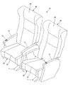
The
図1〜図3に示すように、座席装置10は、客室内のフロア上に固定される脚台11にベースフレーム20が支持され、ベースフレーム20上に2人掛けの座部30および背凭れ40が支持されている。ここで、脚台11に対してベースフレーム20は、回転機構(図示せず)を介して略水平方向に180度回転可能に支持されており、前後逆向きに方向転換できるようになっている。
As shown in FIGS. 1 to 3, in the
各座部30の両側には、それぞれ袖状のアームレストである肘掛け12が設けられている。片側一方の肘掛け12の前端には、操作レバー14が設けられている。操作レバー14は、後述するリクライニング機構におけるロックを解除するための操作部であり、背凭れ40を後方に倒したり、倒れた背凭れ40を元の起立したアップライト位置に戻す等、リクライニング動作を行う際に操作するものである。
On both sides of each
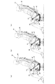
図2に示すように、前記ベースフレーム20は、脚台11の上方に配設された前後一対のシャフト21,22と、各シャフト21,22の両端の前後間を結ぶように固着された左右一対のサイドフレーム23,23から略四角形の枠形状に構成されている。シャフト21,22は、金属製で円形閉断面のパイプ材から成り、サイドフレーム23は、図示した形状の金属製の板状から成る。シャフト21,22は、2つの座部30間に跨がるように左右方向に延びており、2人掛けの本座席装置10では合計2本が使用されている。
As shown in FIG. 2, the
サイドフレーム23は、1つの座部30につき2つ使用されるので、2人掛けの本座席装置10においては、合計4本のサイドフレーム23が、前記シャフト21,22に対して互いに平行な状態となるように固定されている。各サイドフレーム23は全て同一形状であり、それぞれ後述する肘掛け12の内部に設けられ、該肘掛け12のフレーム構造の一部を成している。このようなサイドフレーム23は、前記リクライニング機構の主要部を構成している。
Since two side frames 23 are used for one
リクライニング機構は、座部30および背凭れ40を後方へ傾けるリクライニング動作時に、座部30に対する背凭れ40の支持角度を一定に保った状態で、座部30を後退させつつ前端よりも後端を大きく下降させる座部ガイド15と、背凭れ40を座部30の動きに合わせて後退させつつ後方へ傾けながら下降させる背凭れガイド16と、を有して成る。ここで、座部ガイド15および背凭れガイド16の主要部が、前記サイドフレーム23によって構成されている。
When the reclining mechanism tilts the
詳しく言えば、図1、図2に示すように、サイドフレーム23は、前後方向に延びる形状のうち、前記シャフト21が連結された前部24が略三角形の山型に形成されている。前部24の一辺側に沿うように、略円弧形のガイド溝25が設けられている。このガイド溝25に、後述する座部30を構成する座部フレーム31に設けられている嵌合部34が嵌合してスライド可能に案内される。これにより、リクライニング動作時の座部30の動きが前述したように規制される。
More specifically, as shown in FIGS. 1 and 2, the
また、サイドフレーム23は、前後方向に延びる形状のうち、前記シャフト22が連結された略中間より後端部26にかけて斜め上方に直線状に延びるように形成されている。後端部26には、内側に向けて嵌合部27が突設されている。嵌合部27は、円形断面のピン状あるいは回転可能なローラ状に形成されており、後述する背凭れ40を構成する背凭れフレーム41に設けられているガイド溝45に嵌合してスライド可能に案内される。これにより、リクライニング動作時の背凭れ40の動きが前述したように規制される。
The
図1〜図3に示すように、座部30は、その座部フレーム31にクッション体35を装着し、クッション体35の座面を表皮材で被覆して成る。座部フレーム31は、左右一対の側部32,32と、各側部32の前端間を連結する前部33とから成る。各側部32の後端側は、後述する背凭れ40の背凭れフレーム41に一体に連結されている。ここで、座部フレーム31および背凭れフレーム41は、一つの枠組みによって一体に構成されている。
As shown in FIGS. 1 to 3, the
座部フレーム31および背凭れフレーム41は、例えば、アルミニウム合金等の軽量金属製のパイプ材から組み立てた縦長四角形の枠組みを、座部30と背凭れ40との境界付近で斜めに折り曲げて成る。座部フレーム31を構成する左右の側部32間には、枠形状の開口部分を覆うように複数本の略S字状のスプリング(図示せず)を前後に並ぶように張設すると良い。
The
また、図2に示すように、各側部32の前端寄りの途中には、外側に向かって嵌合部34が設けられている。詳しく言えば、側部32の前端寄りの途中には、下方に延出する舌片状の取付ブラケット32aが固設されている。この取付ブラケット32aの側面に、嵌合部34が外側に向かうように突設されている。ここで嵌合部34は、前記サイドフレーム23にあるガイド溝25に嵌合してスライド可能に案内されるように、円形断面のピン状あるいは回転可能なローラ状に形成されている。なお、ガイド溝25内における嵌合部34の移動と、座部30の具体的なリクライニング動作との関係について、詳しくは後述する。
Further, as shown in FIG. 2, a
座部フレーム31に装着するクッション体35は、例えば、発泡ウレタン等の弾性材質により人間工学に基づいて着座者の臀部に安楽感をもたらす形状に成形されている。本実施の形態では、具体的には図4に示す形状に成形されている。かかるクッション体35の座面は、リクライニング動作に応じた着座者の姿勢の変化に合致するように、着座者を保持する形状に多少変形するが、一連の動きの過程での座面と背凭れ面のなす角度は、椅子をデザインする際に必須となるプロトタイプ(例えば『インテリアの人間工学』,産調出版(株)等参考)の各タイプに順次合致するように設計されている。
The
次に、背凭れ40は、その背凭れフレーム41にクッション体46を装着し、クッション体46の背凭れ面を表皮材で被覆して成る。なお、背凭れ40の背面側には、起倒可能なテーブルが設けられている。背凭れフレーム41は、左右一対の側部42,42と、各側部42の上端間を連結する上部43とから成る。各側部42の下端側は、前記座部フレーム31の各側部32の後端側に一体に連結されている。前述したように、背凭れフレーム41は、座部フレーム31と一つの枠組みによって一体に構成されており、背凭れフレーム41は、前記座部フレーム31の後端より斜め上方に立ち上がるように折り曲げられている。
Next, the
また、図2に示すように、各側部42の下端寄りの途中には、前記サイドフレーム23にある嵌合部27が嵌合してスライド可能に案内されるガイド溝45が設けられている。詳しく言えば、前記側部42の下端寄りの途中には、円弧形状の支持ブラケット44が固設されており、支持ブラケット44の側面に、同じく円弧形状のガイド溝45が設けられている。ここでガイド溝45は、座部30より前方かつ下方の位置に想定されたリクライニング動作の回動中心P(図4(a)参照)を中心とする円周上に沿うように設けられている。
As shown in FIG. 2, a
前記サイドフレーム23に設けたガイド溝25も、前記ガイド溝45と同様に、リクライニング動作の回動中心P(図4(a)参照)を中心とする円周上に沿うように設けられている。すなわち、座部ガイド15のガイド溝25と背凭れガイド16のガイド溝45とは、それぞれ座部30より前方かつ下方の位置に想定されたリクライニング動作の回動中心Pより同心円形に並ぶ円弧状に形成されている。なお、ガイド溝45内における嵌合部27の移動と、背凭れ40の具体的なリクライニング動作との関係について、詳しくは後述する。
Similarly to the
また、前記背凭れフレーム41には、前記肘掛け12を支える肘掛けフレーム13が一体に取り付けられている。図2に示すように、肘掛けフレーム13の後端は、前記側部42の下端寄りの途中に固設されており、この肘掛けフレーム13の後端には、前記支持ブラケット44の一端側も固設されている。このように、肘掛け12の肘掛けフレーム13は、背凭れフレーム41に対して一体に固定されており、肘掛け12も座部30および背凭れ40と一緒に、リクライニング動作を行うように設定されている。なお、肘掛け12は、肘掛けフレーム13から前記サイドフレーム23まで内装するように、リクライニング機構の構成部品の全てを覆う大きさおよび形状に成形されている。
An
さらに、座部30の両側に配された肘掛け12の一方の内部には、座部フレーム31および背凭れフレーム41を、任意の傾斜角度から最も前方へ起立したアップライト位置まで復元させると共に、任意の位置にて前記復元のロックが可能な動力源であるガススプリング50が設けられている。図2に示すように、ガススプリング50は、内部にガスが充填された円筒状のシリンダ51と、該シリンダ51内に摺動可能に挿嵌されたピストン(図示せず)に固着され、該シリンダ51外に伸縮可能に突出したロッド52とから成るが、その構成は一般的であるので詳細な説明は省略する。
Furthermore, in one of the
ガススプリング50は肘掛け12の内部にて、前記サイドフレーム23の略中間と前記肘掛けフレーム13の前端下側との間に架け渡されている。詳しく言えば図2に示すように、シリンダ51の後端がサイドフレーム23の略中間に枢着され、ロッド52の前端が肘掛けフレーム13の前端下側に枢着されている。ここでガススプリング50は、シリンダ51内のガス圧によってロッド52が伸長する方向に常時付勢されており、肘掛け12の前端側を上方に持ち上げる方向、すなわち、座部30および背凭れ40がアップライト位置に復帰する方向に反発力を与えるように設定されている。
The
ガススプリング50はロック機構を備えており、該ロック機構によって任意の伸縮状態でロッド52を固定することができ、座部30および背凭れ40を任意の傾斜角度にロックできるように構成されている。一方、後述する操作レバー14の操作によってロックを解除すると、ガススプリング50からの復元力に抗して背凭れ40に体重をかけて押すことが可能となり、背凭れ40を最も後方へ傾斜したリクライニング位置に至るまでの任意の位置に傾動させることができる。
The
前記ロック機構は、シリンダ51内に設けた弁機構(図示せず)と、該弁機構を開閉操作すべくロッド52から突出したプッシュピン53(図1参照)とから成る。かかるロック機構では、操作レバー14によってプッシュピン53をシリンダ51側に押し込むと、ロッド52の拘束が解除されたロック解除状態となる。一方、操作レバー14によって押し込み動作を解除すると、プッシュピン53が外側に突出して、ロッド52の伸縮動作が禁止されたロック状態となるように構成されている。
The lock mechanism includes a valve mechanism (not shown) provided in the
図1に示すように、操作レバー14の下端側は、その直ぐ下に位置する前記プッシュピン53の先端に対して短いリンク機構54を介して押し引き可能に連結されている。ここで、操作レバー14を一方の側に動かすように操作すると、前記プッシュピン53をシリンダ51側に押し込むことになり、ガススプリング50はロック解除状態となる。一方、操作レバー14を他方の側に動かすように操作すると、プッシュピン53はシリンダ51内の圧力に押されて突出し、ガススプリング50はロック状態となる。
As shown in FIG. 1, the lower end side of the
また、座部30の両側に配された肘掛け12の他方の内部にも、座部フレーム31および背凭れフレーム41を、任意の傾斜角度から最も前方へ起立したアップライト位置まで復元させるガススプリング60が設けられている。かかるガススプリング60も、図2に示すように、内部にガスが充填された円筒状のシリンダ61と、該シリンダ61内に摺動可能に挿嵌されたピストン(図示せず)に固着され、該シリンダ61外に伸縮可能に突出したロッド62とから成る。ただし、ガススプリング60は、単にアップライト位置まで復元させるためだけのものであり、前記ガススプリング50にあるロック機構は設けられていない。
In addition, the
ガススプリング60も前記ガススプリング50と同様に、肘掛け12の内部にて、前記サイドフレーム23の略中間と前記肘掛けフレーム13の前端下側との間に架け渡されている。詳しく言えば図2に示すように、シリンダ61の後端がサイドフレーム23の略中間に枢着され、ロッド62の前端が肘掛けフレーム13の前端下側に枢着されている。ここでガススプリング60は、シリンダ61内のガス圧によってロッド62が伸長する方向に常時付勢されており、肘掛け12の前端側を上方に持ち上げる方向、すなわち座部30および背凭れ40がアップライト位置に復帰する方向に反発力を与えるようになっている。ただし、前述したようにロック機構を有さないため、ガススプリング60がある側の肘掛け12には前記操作レバー14も設けられていない。
Similarly to the
次に、本実施の形態に係る座席装置10の作用を説明する。
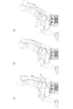
図4に示すように、本座席装置10はリクライニング機構により、同図(a)に示すアップライト状態と、同図(c)に示すリクライニング状態との間にて、着座者が所望の傾斜角度に無段階に調整し保持することができる。同図(b)は、中間の状態を示している。背凭れ40は、座部30の後端側に一体に支持されており、座部30および背凭れ40を後方へ傾けるリクライニング動作時には、座部30に対する背凭れ40の支持角度は常に一定に保たれた状態に維持される。
Next, the operation of the
As shown in FIG. 4, the
また、肘掛け12も、その肘掛けフレーム13が背凭れフレーム41に一体に取り付けられており、肘掛け12も座部30および背凭れ40と一緒にリクライニング動作を行う。このように、座部30や背凭れ40に対する肘掛け12の相対的な位置も、リクライニング動作によって変化することはない。よって、背凭れ40を後方へ倒しても、着座者は同じ姿勢で腕を肘掛け12上に載せておくことができ、リクライニング時にも肩が上がる不自然な姿勢になることはない。
The armrest 12 also has an
リクライニング動作を行う場合には、着座者は先ず肘掛け12の前端にある操作レバー14を操作してガススプリング50のロックを解除し、背中を背凭れ40に押し付けて後方に押すように傾動させる。すると、座部30は座部ガイド15によって、少し後退しつつ該座部30の前端よりも後端が大きく下降するように移動する。同時に、背凭れ40は背凭れガイド16によって、前記座部30の動きに合わせて後退しつつ、全体的に後方へ傾きながら下降するように移動する。
When performing the reclining operation, the seated person first operates the operating
このような図4に示す一連のリクライニング動作は、座部ガイド15におけるガイド溝25の具体的な形状と位置、ガイド溝25内をスライドする嵌合部34、および背凭れガイド16におけるガイド溝45の具体的な形状と位置、ガイド溝45内をスライドする嵌合部27によって実現される。詳しく言えば、図4(a)に示すアップライト位置では、ガイド溝25の上端に嵌合部34は当接し、ガイド溝45の下端に嵌合部27は当接している。図4(b)に示す中間位置を経て、図4(c)に示すリクライニング位置に至ると、嵌合部34はガイド溝25の下端まで移動し、嵌合部27はガイド溝45の上端まで移動する。何れの位置においても、操作レバー14を操作することにより、前記ガススプリング50をロックして当該位置に保持することができる。
Such a series of reclining operations shown in FIG. 4 includes the specific shape and position of the
このようなリクライニング動作によれば、尻ズレ現象や背ズレ現象を確実に防ぐことができ、これらの現象に起因する疲労や不快感を解消でき、より快適な座り心地を得ることができる。しかも、リクライニング前後ないし途中のどの位置においても、前述したように、座部30と背凭れ40のなす角度は変化することなく、着座時の理想の姿勢を維持することができる。特に、本実施の形態では、一連のリクライニング動作の過程において、座部30の座面と背凭れ40の背凭れ面のなす角度は、前述したプロトタイプにおける各タイプに順次合致するように設計されている。
According to such a reclining operation, it is possible to surely prevent the butt shift phenomenon and the back shift phenomenon, eliminate fatigue and discomfort caused by these phenomena, and obtain a more comfortable sitting comfort. Moreover, the ideal posture at the time of sitting can be maintained without changing the angle between the
以上のようなリクライニング機構を成す座部ガイド15や背凭れガイド16は、それぞれベースフレーム20のサイドフレーム23を利用することで簡易に構成することができる。なお、本実施の形態では、座部フレーム31に嵌合部34を設け、ベースフレーム20にガイド溝25を設けたが、逆の態様、すなわち座部フレーム31にガイド溝25を設け、ベースフレーム20に嵌合部34を設けると、肘掛け12と干渉する虞があるためである。一方、ベースフレーム20にガイド溝45を設け、背凭れフレーム41に嵌合部27を設けても、特に問題はない。
The
前記座部ガイド15のガイド溝25と前記背凭れガイド16のガイド溝45とは、それぞれ座部30より前方かつ下方の位置に想定されたリクライニング動作の回動中心P(図4(a)参照)より同心円形に並ぶ円弧状に形成される。このように、座席全体の回動中心を座部30より前方かつ下方の位置、すなわち着座者のくるぶし付近に想定して、この座席より離れた位置にある回動中心の円弧上をスライドさせることにより、背凭れ40後方への倒れ込みを最小限に抑えつつ、十分な傾斜角度を得ることができる。
The
また、座席装置10によれば、座部フレーム31および背凭れフレーム41は、一つの枠組みにより一体に構成される。このような簡易なフレーム構造により、座部30に背凭れ40が一体に支持されて両者のなす角度は常に一定となる。よって、着座時の理想の姿勢を保持しながらリクライニングする目的を達成するために複雑な構造とすることなく、部品点数や組立て工数も大幅に削減され、コストを削減することができる。
Moreover, according to the
さらに、動力源であるガススプリング50やガススプリング60を、従来のように座部30の下側等ではなく、外部に取り外しやすい肘掛け12の内部に設けたことにより、これらガススプリング50やガススプリング60の保守点検を容易に行うことができる。ここでガススプリング50を、その軸方向の先端にあるプッシュピン53を肘掛け12の前端を臨む状態に配置し、このプッシュピン53を間近にある操作レバー14によって操作可能とする。これにより、従来のように肘掛け12前端に設けた操作レバー14に対する操作力を座部30下側などの離れた箇所に設けたガススプリングまでケーブルを配索して伝達する必要もなく、部品点数が削減され、メンテナンス性も改善される。
Further, the
以上、本発明の実施の形態を図面によって説明してきたが、具体的な構成はこれらの実施の形態に限られるものではなく、本発明の要旨を逸脱しない範囲における変更や追加があっても本発明に含まれる。例えば、本実施の形態では2人掛け用として構成したが、1人掛け用あるいは3人掛け用であってもかまわない。また、鉄道車両用の座席に限られるものでもない。また、肘掛け12の肘掛けフレーム13を背凭れフレーム41に一体に取り付けたが、背凭れフレーム41ではなく座部フレーム31側に一体に取り付けるように構成しても良い。
As described above, the embodiments of the present invention have been described with reference to the drawings. However, the specific configuration is not limited to these embodiments, and the present invention can be modified or added without departing from the scope of the present invention. Included in the invention. For example, although the present embodiment is configured for two-seater, it may be for one-seater or three-seater. Moreover, the seat is not limited to a railcar seat. Further, although the
本発明は、特に鉄道車両、航空機、自動車船舶等の客室内に設置される乗物用の座席に広く利用することができる。 The present invention can be widely used particularly for vehicle seats installed in passenger cabins such as railway vehicles, airplanes, and automobile ships.
10…座席装置
11…脚台
12…肘掛け
13…肘掛けフレーム
14…操作レバー
15…座部ガイド
16…背凭れガイド
20…ベースフレーム
23…サイドフレーム
24…前部
25…ガイド溝
26…後端部
27…嵌合部
30…座部
31…座部フレーム
34…嵌合部
35…クッション体
40…背凭れ
41…背凭れフレーム
44…支持ブラケット
45…ガイド溝
46…クッション体
50…ガススプリング
51…シリンダ
52…ロッド
53…プッシュピン
60…ガススプリング
61…シリンダ
62…ロッド
DESCRIPTION OF
Claims (6)
前記リクライニング機構は、前記座部および前記背凭れを後方へ傾けるリクライニング動作時に、前記座部に対する前記背凭れの支持角度を一定に保った状態で、前記座部を後退させつつ前端よりも後端を大きく下降させる座部ガイドと、前記背凭れを前記座部の動きに合わせて後退させつつ後方へ傾けながら下降させる背凭れガイドと、を有して成ることを特徴とする座席装置。 In a seat device provided with a reclining mechanism in which a backrest is integrally supported on the rear end side of the seat portion and an inclination angle of the seat portion and the backrest is adjustable.
The reclining mechanism is configured such that, during a reclining operation in which the seat and the backrest are tilted backward, the backrest with respect to the seat is maintained at a constant support angle while the seat is retracted and the rear end is moved forward than the front end. A seat device, comprising: a seat guide that greatly lowers the backrest; and a backrest guide that lowers the backrest while tilting backward while retracting the backrest according to the movement of the seat portion.
前記座部ガイドは、該座部を構成する座部フレームおよび前記ベースフレームの何れか一方に設けられ、前記座部のリクライニング動作時の動きを規制するガイド溝と、何れか他方に設けられ、前記ガイド溝内に嵌合してスライド可能に案内される嵌合部と、を有し、
前記背凭れガイドは、該背凭れを構成する背凭れフレームおよび前記ベースフレームの何れか一方に設けられ、前記背凭れのリクライニング動作時の動きを規制するガイド溝と、何れか他方に設けられ、前記ガイド溝内に嵌合してスライド可能に案内される嵌合部と、を有することを特徴とする請求項1に記載の座席装置。 The seat and the backrest are supported on a base frame;
The seat guide is provided in any one of the seat frame and the base frame constituting the seat, and is provided in any one of the guide groove for restricting the movement of the seat during the reclining operation, A fitting portion that fits in the guide groove and is slidably guided,
The backrest guide is provided in any one of a backrest frame and the base frame constituting the backrest, provided in a guide groove for regulating movement of the backrest during a reclining operation, and provided in any one of the other. The seat device according to claim 1, further comprising a fitting portion that fits into the guide groove and is slidably guided.
前記肘掛けも前記座部および前記背凭れと一緒に、前記リクライニング動作を行うことを特徴とする請求項2,3または4に記載の座席装置。 Comprising an armrest attached integrally to the seat frame or the back frame;
The seat device according to claim 2, 3 or 4, wherein the armrest also performs the reclining operation together with the seat portion and the backrest.
前記動力源を、前記肘掛けの内部に設けたことを特徴とする請求項5に記載の座席装置。 The seat frame and the backrest frame are restored to an upright position that stands up most forward from an arbitrary inclination angle, and a power source capable of locking the restoration at an arbitrary position is provided.
The seat device according to claim 5, wherein the power source is provided inside the armrest.
Priority Applications (1)
| Application Number | Priority Date | Filing Date | Title |
|---|---|---|---|
| JP2013088054A JP6150597B2 (en) | 2013-04-19 | 2013-04-19 | Seat device |
Applications Claiming Priority (1)
| Application Number | Priority Date | Filing Date | Title |
|---|---|---|---|
| JP2013088054A JP6150597B2 (en) | 2013-04-19 | 2013-04-19 | Seat device |
Publications (2)
| Publication Number | Publication Date |
|---|---|
| JP2014210508A true JP2014210508A (en) | 2014-11-13 |
| JP6150597B2 JP6150597B2 (en) | 2017-06-21 |
Family
ID=51930623
Family Applications (1)
| Application Number | Title | Priority Date | Filing Date |
|---|---|---|---|
| JP2013088054A Active JP6150597B2 (en) | 2013-04-19 | 2013-04-19 | Seat device |
Country Status (1)
| Country | Link |
|---|---|
| JP (1) | JP6150597B2 (en) |
Cited By (4)
| Publication number | Priority date | Publication date | Assignee | Title |
|---|---|---|---|---|
| JP2016120772A (en) * | 2014-12-24 | 2016-07-07 | コイト電工株式会社 | Table device for seat |
| JP2016137133A (en) * | 2015-01-28 | 2016-08-04 | コイト電工株式会社 | Chair |
| US20220266733A1 (en) * | 2019-07-15 | 2022-08-25 | Adient Us Llc | Armrest assembly with armrest moveable between egress position and use position and vehicle seat with moveable armrest |
| CN115886477A (en) * | 2022-11-09 | 2023-04-04 | 佛山市精一家具有限公司 | Synchronous swinging seat |
Citations (7)
| Publication number | Priority date | Publication date | Assignee | Title |
|---|---|---|---|---|
| US5203853A (en) * | 1991-09-18 | 1993-04-20 | Herman Miller, Inc. | Locking chair tilt mechanism with torsion bar |
| JPH0724150U (en) * | 1993-10-15 | 1995-05-09 | 株式会社イトーキクレビオ | Connection structure between the seat and backrest of the chair |
| JPH07506515A (en) * | 1993-01-26 | 1995-07-20 | ゾンダーゲルト ホルスト | adjustable seat |
| JPH09504218A (en) * | 1993-11-01 | 1997-04-28 | ラボファ、アクチセルスカベット | Work chair with seat and back sync adjustment |
| JPH11225851A (en) * | 1998-02-17 | 1999-08-24 | Mr Kenkyusho:Kk | Device for longitudinally sliding chair for use exclusively in pachinko parlor |
| JP2001231651A (en) * | 2000-02-21 | 2001-08-28 | Koito Ind Ltd | Seating apparatus |
| JP2001327353A (en) * | 2000-05-22 | 2001-11-27 | Takano Co Ltd | Chair rocking device |
-
2013
- 2013-04-19 JP JP2013088054A patent/JP6150597B2/en active Active
Patent Citations (7)
| Publication number | Priority date | Publication date | Assignee | Title |
|---|---|---|---|---|
| US5203853A (en) * | 1991-09-18 | 1993-04-20 | Herman Miller, Inc. | Locking chair tilt mechanism with torsion bar |
| JPH07506515A (en) * | 1993-01-26 | 1995-07-20 | ゾンダーゲルト ホルスト | adjustable seat |
| JPH0724150U (en) * | 1993-10-15 | 1995-05-09 | 株式会社イトーキクレビオ | Connection structure between the seat and backrest of the chair |
| JPH09504218A (en) * | 1993-11-01 | 1997-04-28 | ラボファ、アクチセルスカベット | Work chair with seat and back sync adjustment |
| JPH11225851A (en) * | 1998-02-17 | 1999-08-24 | Mr Kenkyusho:Kk | Device for longitudinally sliding chair for use exclusively in pachinko parlor |
| JP2001231651A (en) * | 2000-02-21 | 2001-08-28 | Koito Ind Ltd | Seating apparatus |
| JP2001327353A (en) * | 2000-05-22 | 2001-11-27 | Takano Co Ltd | Chair rocking device |
Cited By (5)
| Publication number | Priority date | Publication date | Assignee | Title |
|---|---|---|---|---|
| JP2016120772A (en) * | 2014-12-24 | 2016-07-07 | コイト電工株式会社 | Table device for seat |
| JP2016137133A (en) * | 2015-01-28 | 2016-08-04 | コイト電工株式会社 | Chair |
| US20220266733A1 (en) * | 2019-07-15 | 2022-08-25 | Adient Us Llc | Armrest assembly with armrest moveable between egress position and use position and vehicle seat with moveable armrest |
| CN115886477A (en) * | 2022-11-09 | 2023-04-04 | 佛山市精一家具有限公司 | Synchronous swinging seat |
| CN115886477B (en) * | 2022-11-09 | 2023-11-28 | 佛山市精一家具有限公司 | Synchronous swinging seat |
Also Published As
| Publication number | Publication date |
|---|---|
| JP6150597B2 (en) | 2017-06-21 |
Similar Documents
| Publication | Publication Date | Title |
|---|---|---|
| US8579375B2 (en) | Aircraft seat | |
| JP5375240B2 (en) | Seat device | |
| US8960785B2 (en) | Vehicle seat | |
| US20070228794A1 (en) | Aircraft passenger seat | |
| JP6150597B2 (en) | Seat device | |
| JP2018197101A (en) | Vehicle passenger chair having rest configuration | |
| CN102092316B (en) | There is the seat of deformable backrest | |
| JP6041618B2 (en) | Seat device | |
| JP2017094958A (en) | Seat support mechanism | |
| CN111731165B (en) | Fold and dive seat for vehicle | |
| JP2015012909A (en) | Seat device | |
| AU2006275207B2 (en) | A chair or a bed having a seat, a backrest and an armrest as well as use thereof | |
| CN110114242B (en) | Armchair comprising an adjustable headrest | |
| JP4624689B2 (en) | Seat device | |
| JP5339344B2 (en) | Chair with reclining mechanism | |
| KR101469438B1 (en) | Reclining Seat operated together with seat cushion | |
| US11939063B2 (en) | Reclining seat | |
| GB2513251A (en) | Seat for a vehicle, in particular a passenger vehicle | |
| JP5627353B2 (en) | Seat device | |
| JP2015020517A (en) | Seat device | |
| JP7449756B2 (en) | seat equipment | |
| JP7352435B2 (en) | Railway vehicle seats | |
| JP6584077B2 (en) | Bucket seat structure and passenger seat with adjustable position | |
| JP2023173122A (en) | Seat device | |
| KR20220163702A (en) | Vehicle seat having legrest with seat cushion function |
Legal Events
| Date | Code | Title | Description |
|---|---|---|---|
| A621 | Written request for application examination |
Free format text: JAPANESE INTERMEDIATE CODE: A621 Effective date: 20160412 |
|
| A977 | Report on retrieval |
Free format text: JAPANESE INTERMEDIATE CODE: A971007 Effective date: 20161214 |
|
| A131 | Notification of reasons for refusal |
Free format text: JAPANESE INTERMEDIATE CODE: A131 Effective date: 20161220 |
|
| A521 | Request for written amendment filed |
Free format text: JAPANESE INTERMEDIATE CODE: A523 Effective date: 20170217 |
|
| TRDD | Decision of grant or rejection written | ||
| A01 | Written decision to grant a patent or to grant a registration (utility model) |
Free format text: JAPANESE INTERMEDIATE CODE: A01 Effective date: 20170425 |
|
| A61 | First payment of annual fees (during grant procedure) |
Free format text: JAPANESE INTERMEDIATE CODE: A61 Effective date: 20170523 |
|
| R150 | Certificate of patent or registration of utility model |
Ref document number: 6150597 Country of ref document: JP Free format text: JAPANESE INTERMEDIATE CODE: R150 |
|
| R250 | Receipt of annual fees |
Free format text: JAPANESE INTERMEDIATE CODE: R250 |