JP2014161966A - Machine tool comprising movable cover - Google Patents
Machine tool comprising movable cover Download PDFInfo
- Publication number
- JP2014161966A JP2014161966A JP2013035875A JP2013035875A JP2014161966A JP 2014161966 A JP2014161966 A JP 2014161966A JP 2013035875 A JP2013035875 A JP 2013035875A JP 2013035875 A JP2013035875 A JP 2013035875A JP 2014161966 A JP2014161966 A JP 2014161966A
- Authority
- JP
- Japan
- Prior art keywords
- cover
- machine tool
- saddle
- movable cover
- cutting fluid
- Prior art date
- Legal status (The legal status is an assumption and is not a legal conclusion. Google has not performed a legal analysis and makes no representation as to the accuracy of the status listed.)
- Pending
Links
Images


Classifications
-
- B—PERFORMING OPERATIONS; TRANSPORTING
- B23—MACHINE TOOLS; METAL-WORKING NOT OTHERWISE PROVIDED FOR
- B23Q—DETAILS, COMPONENTS, OR ACCESSORIES FOR MACHINE TOOLS, e.g. ARRANGEMENTS FOR COPYING OR CONTROLLING; MACHINE TOOLS IN GENERAL CHARACTERISED BY THE CONSTRUCTION OF PARTICULAR DETAILS OR COMPONENTS; COMBINATIONS OR ASSOCIATIONS OF METAL-WORKING MACHINES, NOT DIRECTED TO A PARTICULAR RESULT
- B23Q11/00—Accessories fitted to machine tools for keeping tools or parts of the machine in good working condition or for cooling work; Safety devices specially combined with or arranged in, or specially adapted for use in connection with, machine tools
- B23Q11/08—Protective coverings for parts of machine tools; Splash guards
-
- B—PERFORMING OPERATIONS; TRANSPORTING
- B23—MACHINE TOOLS; METAL-WORKING NOT OTHERWISE PROVIDED FOR
- B23Q—DETAILS, COMPONENTS, OR ACCESSORIES FOR MACHINE TOOLS, e.g. ARRANGEMENTS FOR COPYING OR CONTROLLING; MACHINE TOOLS IN GENERAL CHARACTERISED BY THE CONSTRUCTION OF PARTICULAR DETAILS OR COMPONENTS; COMBINATIONS OR ASSOCIATIONS OF METAL-WORKING MACHINES, NOT DIRECTED TO A PARTICULAR RESULT
- B23Q11/00—Accessories fitted to machine tools for keeping tools or parts of the machine in good working condition or for cooling work; Safety devices specially combined with or arranged in, or specially adapted for use in connection with, machine tools
- B23Q11/0042—Devices for removing chips
- B23Q11/0053—Devices for removing chips using the gravity force
-
- B—PERFORMING OPERATIONS; TRANSPORTING
- B23—MACHINE TOOLS; METAL-WORKING NOT OTHERWISE PROVIDED FOR
- B23Q—DETAILS, COMPONENTS, OR ACCESSORIES FOR MACHINE TOOLS, e.g. ARRANGEMENTS FOR COPYING OR CONTROLLING; MACHINE TOOLS IN GENERAL CHARACTERISED BY THE CONSTRUCTION OF PARTICULAR DETAILS OR COMPONENTS; COMBINATIONS OR ASSOCIATIONS OF METAL-WORKING MACHINES, NOT DIRECTED TO A PARTICULAR RESULT
- B23Q11/00—Accessories fitted to machine tools for keeping tools or parts of the machine in good working condition or for cooling work; Safety devices specially combined with or arranged in, or specially adapted for use in connection with, machine tools
- B23Q11/08—Protective coverings for parts of machine tools; Splash guards
- B23Q11/0825—Relatively slidable coverings, e.g. telescopic
-
- Y—GENERAL TAGGING OF NEW TECHNOLOGICAL DEVELOPMENTS; GENERAL TAGGING OF CROSS-SECTIONAL TECHNOLOGIES SPANNING OVER SEVERAL SECTIONS OF THE IPC; TECHNICAL SUBJECTS COVERED BY FORMER USPC CROSS-REFERENCE ART COLLECTIONS [XRACs] AND DIGESTS
- Y02—TECHNOLOGIES OR APPLICATIONS FOR MITIGATION OR ADAPTATION AGAINST CLIMATE CHANGE
- Y02P—CLIMATE CHANGE MITIGATION TECHNOLOGIES IN THE PRODUCTION OR PROCESSING OF GOODS
- Y02P70/00—Climate change mitigation technologies in the production process for final industrial or consumer products
- Y02P70/10—Greenhouse gas [GHG] capture, material saving, heat recovery or other energy efficient measures, e.g. motor control, characterised by manufacturing processes, e.g. for rolling metal or metal working
-
- Y—GENERAL TAGGING OF NEW TECHNOLOGICAL DEVELOPMENTS; GENERAL TAGGING OF CROSS-SECTIONAL TECHNOLOGIES SPANNING OVER SEVERAL SECTIONS OF THE IPC; TECHNICAL SUBJECTS COVERED BY FORMER USPC CROSS-REFERENCE ART COLLECTIONS [XRACs] AND DIGESTS
- Y10—TECHNICAL SUBJECTS COVERED BY FORMER USPC
- Y10T—TECHNICAL SUBJECTS COVERED BY FORMER US CLASSIFICATION
- Y10T409/00—Gear cutting, milling, or planing
- Y10T409/30—Milling
- Y10T409/309576—Machine frame
-
- Y—GENERAL TAGGING OF NEW TECHNOLOGICAL DEVELOPMENTS; GENERAL TAGGING OF CROSS-SECTIONAL TECHNOLOGIES SPANNING OVER SEVERAL SECTIONS OF THE IPC; TECHNICAL SUBJECTS COVERED BY FORMER USPC CROSS-REFERENCE ART COLLECTIONS [XRACs] AND DIGESTS
- Y10—TECHNICAL SUBJECTS COVERED BY FORMER USPC
- Y10T—TECHNICAL SUBJECTS COVERED BY FORMER US CLASSIFICATION
- Y10T82/00—Turning
- Y10T82/25—Lathe
- Y10T82/2572—Attachment
Landscapes
- Engineering & Computer Science (AREA)
- Mechanical Engineering (AREA)
- Auxiliary Devices For Machine Tools (AREA)
Abstract
Description
本発明は、可動カバーを備えた工作機械に関する。 The present invention relates to a machine tool provided with a movable cover.
工作機械は、加工中に発生した切粉が機械の外に飛散するのを防ぐために、加工空間をスプラッシュガードと呼ばれるカバーで覆っている。加工中に発生する切粉がテーブルに固定されるテレスコピックカバーの上に堆積したり、カバー(スプラッシュガード)とテレスコピックカバーの隙間や下側に入り込む場合がある。 A machine tool covers a machining space with a cover called a splash guard in order to prevent chips generated during machining from scattering outside the machine. Chips generated during processing may accumulate on the telescopic cover fixed to the table, or may enter the gap or the lower side of the cover (splash guard) and the telescopic cover.
この対策として、ドアの開閉に連動してテレスコピックカバーの上に堆積した切粉をワイパーで掻き落す方法(特許文献1参照)、カバー(スプラッシュガード)とテレスコピックカバーの隙間を覆う別カバーを追加する方法、隙間に切粉を受けるための溝を設けてこの溝の中に切粉搬送装置を設ける方法(特許文献2参照委)が、従来公知である。 As countermeasures, a method of scraping off chips accumulated on the telescopic cover in conjunction with opening and closing of the door with a wiper (see Patent Document 1), and adding another cover that covers the gap between the cover (splash guard) and the telescopic cover Conventionally, a method and a method of providing a chip for receiving chips in the gap and providing a chip conveying device in the groove (see Patent Document 2) are conventionally known.
特許文献1に示される方法では、テレスコピックカバーの上に堆積した切粉をドアの開閉時に掻き落すため、加工が長時間に及び、ドアの開閉が行なわれない状況が続いた場合、切粉が堆積する一方となり、カバーの動作に支障をきたす可能性があるが、これに対する解決方法については記載も示唆もされていない。
In the method shown in
また、スプラッシュガードとテレスコピックカバーの隙間を別板金で塞ぎ、駆動部に切粉が入り込むのを防いでいるが、別部品が必要となってコストがアップすることや、密閉度において改善の余地がある。 In addition, the gap between the splash guard and the telescopic cover is closed with a separate sheet metal to prevent chips from entering the drive unit, but additional parts are required, increasing costs and leaving room for improvement in sealing. is there.
特許文献2に示される方法では、スプラッシュガードとテレスコピックカバーの隙間に溝を設け、この中に切粉搬送装置を設置しているが、スプラッシュガードの底面から一定距離高い部分に重量の切粉搬送装置を設置するためにカバーを頑丈にすることが必要となり、構造が大型化しコストアップとなり、また、溝下側の空間に切粉が回り込んで堆積する問題もある。
In the method disclosed in
また、特許文献1、2に開示される技術は、加工中に発生する切粉がスプラッシュガードの下側に入り込んで、テーブルやサドルの駆動部(直動ガイドや送りボールねじ)やその近傍に堆積することを防止することができない、という問題がある。
In addition, in the techniques disclosed in
そこで本発明の目的は、上記従来技術の問題点を鑑み、切粉がスプラッシュガードの下側に入り込んでテーブルやサドルの駆動部(直動ガイドや送りボールねじ)やその近傍に堆積することを防止し、機械の故障を抑制することが可能な可動カバーを備えた工作機械を提供することである。 Therefore, in view of the above-mentioned problems of the prior art, the object of the present invention is to allow chips to enter the lower side of the splash guard and deposit on the table or saddle drive unit (linear guide or feed ball screw) or in the vicinity thereof. It is an object of the present invention to provide a machine tool including a movable cover that can prevent and suppress machine failure.
本願の請求項1に係る発明は、ベッドに設けられた第1のガイド部材に支持され、前記ベッドに対して第1の方向に相対移動するサドルと、該サドルに設けられた第2のガイド部材に支持され、前記第1の方向と交差する第2の方向に前記サドルに対して相対移動するテーブルと、主軸を有するコラムと、前記ベッドの周囲を覆うカバーとを有し、前記テーブルを挟んで前記コラムと対向する側に設けられた前面カバーと、この前面カバーの左右に設けられた側面カバーと、前記前面カバーおよび前記側面カバーから前記ベッドに接続される底部を有し、主軸に装着された工具と前記テーブルに設置されたワークとの間で相対移動を行なわせワークを加工する工作機械において、前記サドルの第1方向の両側面もしくは片側面に設けられ、それぞれ両端もしくは片端が前記カバーに固定され、前記サドルの移動と共に伸縮する可動カバーと、前記可動カバーの内側に前記第一の方向に延設される底面から突出した壁部、とを設けたことを特徴とする可動カバーを備えた工作機械である。
請求項2に係る発明は、前記第一の方向に延設される底面から突出した壁部は、前記可動カバーの幅より僅か内側になるように形成されていることを特徴とする請求項1に記載の可動カバーを備えた工作機械である。
請求項3に係る発明は、前記第一の方向に延設される底面から突出した壁部は、機械の前後方向または左右方向に形成されていることを特徴とする請求項1または2のいずれか1つに記載の可動カバーを備えた工作機械である。
請求項4に係る発明は、前記第一の方向に延設される底面から突出した壁部は、前記カバーと一体で形成されているか、別部材として取り付けられて形成されているか、または、前記カバーの底面を盛り上げて形成しているかの何れか1つで形成されていることを特徴とする請求項1〜3のいずれか1つであることを特徴とする可動カバーを備えた工作機械である。
The invention according to
The invention according to
The invention according to
In the invention according to
請求項5に係る発明は、前記第1の方向は前記側面カバーと平行な方向であり、前記側面カバーの前記底部が、前記工作機械の前方から後方、又は後方から前方に向かって低くなることを特徴とする請求項1〜4のいずれか1つに記載の可動カバーを備えた工作機械である。
請求項6に係る発明は、前記第1の方向は前記側面カバーと平行な方向であり、前記左右の側面カバーの前記底部の一方が前記工作機械の前方から後方に低くなり、他方が後方から前方に向かって低くなることを特徴とする請求項1〜4のいずれか1つに記載の可動カバーを備えた工作機械である。
請求項7に係る発明は、前記第1の方向は前記前面カバーと平行な方向であり、前記底面から突出した壁部により分離された前記前面カバーの前記底部および側面カバーの前記底部それぞれを任意の方向に傾斜させたことを特徴とする請求項1〜4のいずれか1つに記載の可動カバーを備えた工作機械である。
請求項8に係る発明は、前記伸縮自在な可動カバー上面に切削液を供給することを特徴とする請求項1〜7のいずれか1つに記載の可動カバーを備えた工作機械である。
請求項9に係る発明は、前記分離された前記底部に切削液を供給することを特徴とする請求項1〜8のいずれか1つに記載の可動カバーを備えた工作機械である。
In the invention according to claim 5, the first direction is a direction parallel to the side cover, and the bottom portion of the side cover is lowered from the front to the rear of the machine tool or from the rear to the front. A machine tool comprising the movable cover according to any one of
In the invention according to
In the invention according to
The invention according to claim 8 is the machine tool provided with the movable cover according to any one of
The invention according to
本発明により、切粉がスプラッシュガードの下側に入り込んで、テーブルやサドルの駆動部(直動ガイドや送りボールねじ)やその近傍に堆積することを防止し、機械の故障を抑制することが可能な可動カバーを備えた工作機械を提供できる。 According to the present invention, it is possible to prevent chips from entering the lower side of the splash guard and accumulating on the table or saddle drive part (linear motion guide or feed ball screw) or in the vicinity thereof, thereby suppressing machine failure. A machine tool having a movable cover that can be provided can be provided.
以下、本発明の実施形態を図面と共に説明する。類似する構成要素について実施形態が異なっても同じ符号を用いて説明する。
<実施形態1>
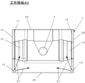
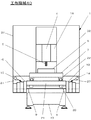
図1は実施形態1の機械上面の模式図である。図2は実施形態1の機械正面の模式図である。スプラッシュガードと呼ばれるカバー1は、サドル21、テーブル7、コラム18、主軸4、工具5を外部から隔離し、加工空間を形成する。カバー1は、テーブル7を挟んでコラム18と対向する側に設けた前面カバー30と、前面カバー30の左右に設けられた側面カバー31,32と、後面カバー33などから構成され、前面カバー30、側面カバー31,32は、各々の下端からベッド19に接続される底部を有する。底部によってカバー1の底面が形成される。前面カバー30、側面カバー31,32から独立した部材として前記底部を構成してもよい。なお、天井カバーについては図示省略している。
Hereinafter, embodiments of the present invention will be described with reference to the drawings. Similar components will be described using the same reference numerals even if the embodiments are different.
<
FIG. 1 is a schematic view of the upper surface of the machine according to the first embodiment. FIG. 2 is a schematic front view of the machine according to the first embodiment. The
ベッド19上にサドル移動機構20を介してサドル21が支持され、サドル21上にテーブル移動機構22を介してワーク6を載置するテーブル7が支持されている。さらに、ベッド19上にコラム18が立設され、コラム18の上部に工具5を装着する主軸4が固定されている。工作機械40は、主軸4とテーブル7とを加工空間内で相対移動させることで、テーブル7上に載置されたワーク6の切削加工を行う。サドル移動機構20、テーブル移動機構22は、それぞれ、レール、該レールに案内されるガイドから構成される。サドル21の移動方向(第1の方向)とテーブル7の移動方向(第2の方向)とは交差している。なお、実施形態1では、サドル21の移動方向(第1の方向)は機械の前後方向に対応する。
A
カバー1によって隔離された加工空間に切削液を供給するために、左切削液供給流路11と右切削液供給流路12が加工空間に配設されている。図示しない切削液供給装置から図示しない流路を介して左切削液供給流路11と右切削液供給流路12に切削液が供給される。左切削液供給流路11の所定個所に第1切削液供給ノズル13が設けられ、右切削液供給流路12の所定個所に第2切削液供給ノズル14が設けられている。第1,第2切削供給ノズル13,14から、加工空間内の所定方向に向かって切削液が放出される(切削液の流れ27を参照)。例えば、テレスコピックカバー10の上面やカバー1の底部(左底面2、右底面3)に切削液が放出される。
In order to supply the cutting fluid to the machining space isolated by the
加工中に発生する切粉がサドルの駆動部(レールや送りねじ)に堆積するのを防止するために、テレスコピックカバー10が用いられている。テレスコピックカバー10は、その伸縮方向がテレスコピックカバー10の伸縮方向と同じとなるように、サドル21と前面カバー30の間に配設されている。テレスコピックカバー10の一端はサドル21に固定され、他端はカバー1(前面カバー30)に固定されている。
A
壁部9が、テレスコピックカバー10の下側のカバー1の底面に機械の前後方向の向きに設けられている。壁部9はテレスコピックカバー10の伸縮に干渉しないようにカバー1の底面に設けられる。そのため、壁部9の幅は、テレスコピックカバー10の伸縮方向に対して直交する方向の幅より僅かに小さく、壁部9の側面によって、テレスコピックカバー10の下側部分のカバー1の底面とテレスコピックカバー10の外側部分のカバー1の底面との間が仕切られた構造が形成される。壁部9の高さはテレスコピックカバー10の伸縮動作に干渉しない範囲の高さとする。壁部9がテレスコピックカバー10の伸縮方向に対して直交する方向の幅より僅かに小さく構成されることで、テレスコピックカバー10の側面部の内側と壁部9の側面との間には隙間が殆ど無くなる(図4参照)。このため、切粉がテレスコピックカバー10の下側に回り込み、サドル21の駆動部やその近傍に堆積することを防止できる。図4に示されるように、テレスコピックカバー10と壁部9eの側面との間の隙間(破線部34,破線部35を参照)が僅かであることから、切粉がテレスコピックカバー10の下側に回り込み、テレスコピックカバー10の下側に堆積することを防止できる。
A
壁部9はカバー1の底面を盛り上げた場合や、天井となる部分も持つ別部材を取り付けた場合は、天井部分に傾斜をつけて切粉の堆積を防ぐ構造とするとよい。壁の形状は単純な垂直の壁、壁の上部に壁同士を結合する天井部分をともなう壁、ドーム状の壁など、テレスコピックカバーに干渉しない、いかなる形状も可能とする。さらに、壁の数も2個に限定するものではない。
When the bottom surface of the
図3に壁部9の形状例を示す(断面形状)。図3(a)に示される壁部9は、天井となる部分を持ち、外側側面とテレスコピックカバー10との間の隙間が僅かとなる外形形状を備えている。図3(b)に示される壁部9は、内部が中空である天井となる部分を持ち、外側側面とテレスコピックカバー10との間の隙間が僅かとなる外形形状を備えている。図3(c),図3(d)は底面を盛り上げた形状を有し、図3(c)は断面矩形状に底面を盛り上げ、図(d)は断面を楕円形状に盛り上げている。図3(e),図3(f),図3(g),図3(h)図は2つの壁部分が基部から立ち上がる断面形状を有する。2つの壁部分の形状は図3(e)〜図3(h)に示されるように種々ある。
FIG. 3 shows an example of the shape of the wall 9 (cross-sectional shape). The
壁部9は、カバー1と一体で形成してもよいし、テレスコピックカバー10の下側が盛り上がるようにカバー1の底面を形成してもよい。あるいは、図3に示されるような壁部9をカバー1の底面に別部材として取り付けてもよい。
The
図5は、実施形態1における切削液の流れ方向を説明する図である。カバー1の底部の傾斜を図5の右側のように傾斜させると、切削液は傾斜方向に向かってながれ、図示しない切削液回収装置に回収される。
FIG. 5 is a diagram illustrating the flow direction of the cutting fluid in the first embodiment. When the inclination of the bottom portion of the
さらに左右の底面部分(左底面2,右底面3)は、カバーの前面から後面に対して低くなるように傾斜させる。テレスコピックカバー10の上と左右の底面部分の傾斜面に対して切削液を供給し、堆積した切粉を除去し、切削液供給装置(図示せず)に排出する。カバー(スプラッシュガード)1の底面を盛り上げた場合や別部材を取り付けた場合は、その部分に切削液を供給しても良い。一方、テレスコピックカバー10は、カバー1の底面に設けた壁部9の中央の盛り上がり部分を覆う形とし、高さ方向も壁部9に干渉しない範囲で高くする。
Further, the left and right bottom portions (left
実施形態1では、加工によって発生した切粉が伸縮自在なテレスコピックカバー10に堆積すると、テーブル7の移動に伴うカバーの伸縮と、左,右切削液供給流路11、12に設けられた第1,第2切削液供給ノズル13、14から切削液の供給とにより、テレスコピックカバー10の表面に堆積した切粉はテレスコピックカバー10から左底面2もしくは右底面3に落下する。左底面2もしくは右底面3に落下した切粉を、左切削液供給流路11、右切削液供給流路12、第1切削液供給ノズル13、第2切削液供給ノズル14から切削液を供給することにより、加工液供給装置へ排出する。
In the first embodiment, when chips generated by processing are deposited on the
これらの方法では、テレスコピックカバー10の下側に切粉が堆積せず、切粉を駆動部(サドルの駆動手段)から遠ざけることが可能となる。又、テレスコピックカバー10の下側の切粉が堆積しやすい空間を無くすとともに、駆動部であるレールや送りねじに切粉が付着するのを防ぐことができる。結果として、機械の故障を防いで信頼性を向上することができる。
In these methods, chips do not accumulate on the lower side of the
これにより、切粉の溜まり易いテレスコピックカバー10の下側のテーブル前面部分のスペースを無くし、左,右底面2,3の切粉を確実に効率よく排出し、切削液処理装置(図示せず)に回収することができる。又、機械の駆動部に切粉が進入するのを防ぎ、耐切粉性を向上することができる。
This eliminates the space on the front surface of the table on the lower side of the
<実施形態2>
図6は実施形態1の機械上面の模式図である。図7は実施形態1の機械正面の模式図である。スプラッシュガードと呼ばれるカバー1は、サドル21、テーブル7、コラム18、主軸4、工具5を外部から隔離し、加工空間を形成する。カバー1は、テーブル7を挟んでコラム18と対向する側に設けた前面カバー30と、前面カバー30の左右に設けられた側面カバー31,32と、後面カバー33などから構成され、前面カバー30、側面カバー31,32は、各々の下端からベッドに接続される底部を有する。底部によってカバー1の底面が形成される。前面カバー30、側面カバー31,32から独立した部材として前記底部を構成してもよい。なお、天井カバーについては図示省略している。
<
FIG. 6 is a schematic view of the upper surface of the machine according to the first embodiment. FIG. 7 is a schematic diagram of the front of the machine according to the first embodiment. The
ベッド19上にサドル移動機構20を介してサドル21が支持され、サドル21上にテーブル移動機構22を介してワーク6を載置するテーブル7が支持されている。さらに、ベッド19上にコラム18が立設され、コラム18の上部に工具5を装着する主軸4が固定されている。工作機械40は、主軸4とテーブル7とを加工空間内で相対移動させることで、テーブル7上に載置されたワーク6の切削加工を行う。サドル移動機構20、テーブル移動機構22は、それぞれ、レール、該レールに案内されるガイドから構成される。サドル21の移動方向(第1の方向)とテーブル7の移動方向(第2の方向)とは直交している。なお、実施形態1では、サドル21の移動方向(第1の方向)は機械の左右方向に対応する。
A
カバー1によって隔離された加工空間に切削液を供給するために、左切削液供給流路11と右切削液供給流路12が加工空間に配設されている。図示しない切削液供給装置から図示しない流路を介して左切削液供給流路11と右切削液供給流路12に切削液が供給される。左切削液供給流路11の所定個所に第1切削液供給ノズル13が設けられ、右切削液供給流路12の所定個所に第2切削液供給ノズル14が設けられている。第1,第2切削供給ノズル13,14から、加工空間内の所定方向に向かって切削液が放出される(切削液の流れ27を参照)。
In order to supply the cutting fluid to the machining space isolated by the
加工中に発生する切粉がサドルの駆動部(ガイドや送りねじ)に堆積するのを防止するために、テレスコピックカバー10が用いられている。テレスコピックカバー10は、その伸縮方向がテレスコピックカバー10の伸縮方向と同じとなるように、サドル21と前面カバー30の間に配設されている。テレスコピックカバー10の一端はサドル21に固定され、他端はカバー1(前面カバー30)に固定されている。
A
壁部9が、テレスコピックカバー10の下側のカバー1の底面に機械の左右方向の向きに設けられている。壁部9はテレスコピックカバー10の伸縮に干渉しないようにカバー1の底面に設けられる。そのため、壁部9の幅は、テレスコピックカバー10の伸縮方向に対して直交する方向の幅より僅かに小さく、壁部9の側面によって、テレスコピックカバー10の下側部分のカバー1の底面とテレスコピックカバー10の外側部分のカバー1の底面との間が仕切られた構造が形成される。壁部9の高さはテレスコピックカバー10の伸縮動作に干渉しない範囲の高さとする。壁部9がテレスコピックカバー10の伸縮方向に対して直交する方向の幅より僅かに小さく構成されることで、テレスコピックカバー10の側面部の内側と壁部9の側面との間には隙間が殆ど無くなる。このため、切粉がテレスコピックカバー10の下側に回り込み、サドル21の駆動部やその近傍に堆積することを防止できる。図4に示されるように、テレスコピックカバー10と壁部9eの側面との間の隙間(破線部34,破線部35を参照)が僅かであることから、切粉がテレスコピックカバー10の下側に回り込み、テレスコピックカバー10の下側に堆積することを防止できる。
A
図8は、実施形態2における切削液の流れ方向を説明する図である。カバー1の底部の傾斜を図5の右側のように傾斜させると、切削液は傾斜方向に向かってながれ、図示しない切削液回収装置に回収される。
FIG. 8 is a diagram illustrating the flow direction of the cutting fluid in the second embodiment. When the inclination of the bottom portion of the
1 カバー
2 左底面
3 右底面
4 主軸
5 工具
6 ワーク
7 テーブル
9 壁部
9e 壁部
10 テレスコピックカバー
11 左切削液供給流路
12 右切削液供給流路
13 第1切削液供給ノズル
14 第2切削液供給ノズル
18 コラム
19 ベッド
20 サドル移動機構
21 サドル
22 テーブル移動機構
27 切削液の流れ
30 前面カバー
31 側面カバー
32 側面カバー
33 後面カバー
40 工作機械
1
9 Wall portion 9e
18
27 Flow of cutting fluid
30
40 machine tools
Claims (9)
前記テーブルを挟んで前記コラムと対向する側に設けられた前面カバーと、この前面カバーの左右に設けられた側面カバーと、前記前面カバーおよび前記側面カバーから前記ベッドに接続される底部を有し、
主軸に装着された工具と前記テーブルに設置されたワークとの間で相対移動を行なわせワークを加工する工作機械において、
前記サドルの第1方向の両側面もしくは片側面に設けられ、それぞれ両端もしくは片端が前記カバーに固定され、前記サドルの移動と共に伸縮する可動カバーと、
前記可動カバーの内側に前記第一の方向に延設される底面から突出した壁部、
とを設けたことを特徴とする可動カバーを備えた工作機械。 A saddle supported by a first guide member provided on the bed and relatively moved in the first direction with respect to the bed, and a second guide member provided on the saddle and supported by the first direction. A table that moves relative to the saddle in a second direction that intersects with the saddle, a column having a main shaft, and a cover that covers the periphery of the bed,
A front cover provided on the side facing the column across the table, side covers provided on the left and right sides of the front cover, and a bottom portion connected to the bed from the front cover and the side cover ,
In a machine tool for machining a workpiece by performing relative movement between a tool mounted on a spindle and a workpiece installed on the table,
A movable cover provided on both side surfaces or one side surface of the saddle in the first direction, both ends or one end being fixed to the cover, and extending and contracting with the movement of the saddle;
A wall portion protruding from the bottom surface extending in the first direction inside the movable cover;
A machine tool with a movable cover, characterized in that
前記側面カバーの前記底部が、前記工作機械の前方から後方、又は後方から前方に向かって低くなることを特徴とする請求項1〜4のいずれか1つに記載の可動カバーを備えた工作機械。 The first direction is a direction parallel to the side cover;
The machine tool with a movable cover according to any one of claims 1 to 4, wherein the bottom portion of the side cover is lowered from the front to the rear of the machine tool or from the rear to the front. .
前記左右の側面カバーの前記底部の一方が前記工作機械の前方から後方に低くなり、他方が後方から前方に向かって低くなることを特徴とする請求項1〜4のいずれか1つに記載の可動カバーを備えた工作機械。 The first direction is a direction parallel to the side cover;
The one of the bottom parts of the left and right side covers is lowered from the front to the rear of the machine tool, and the other is lowered from the rear to the front. A machine tool with a movable cover.
前記底面から突出した壁部により分離された前記前面カバーの前記底部および側面カバーの前記底部それぞれを任意の方向に傾斜させたことを特徴とする請求項1〜4のいずれか1つに記載の可動カバーを備えた工作機械。 The first direction is a direction parallel to the front cover;
The said bottom part of the said front cover and the said bottom part of the side surface cover which were isolate | separated by the wall part protruded from the said bottom face were made to incline in arbitrary directions, The Claim 1 characterized by the above-mentioned. A machine tool with a movable cover.
Priority Applications (4)
| Application Number | Priority Date | Filing Date | Title |
|---|---|---|---|
| JP2013035875A JP2014161966A (en) | 2013-02-26 | 2013-02-26 | Machine tool comprising movable cover |
| US14/181,916 US20140238206A1 (en) | 2013-02-26 | 2014-02-17 | Machine tool equipped with movable cover |
| DE102014102377.3A DE102014102377A1 (en) | 2013-02-26 | 2014-02-24 | Machine tool with movable cover |
| CN201410063251.4A CN104002185A (en) | 2013-02-26 | 2014-02-25 | Machine tool equipped with movable cover |
Applications Claiming Priority (1)
| Application Number | Priority Date | Filing Date | Title |
|---|---|---|---|
| JP2013035875A JP2014161966A (en) | 2013-02-26 | 2013-02-26 | Machine tool comprising movable cover |
Publications (1)
| Publication Number | Publication Date |
|---|---|
| JP2014161966A true JP2014161966A (en) | 2014-09-08 |
Family
ID=51349638
Family Applications (1)
| Application Number | Title | Priority Date | Filing Date |
|---|---|---|---|
| JP2013035875A Pending JP2014161966A (en) | 2013-02-26 | 2013-02-26 | Machine tool comprising movable cover |
Country Status (4)
| Country | Link |
|---|---|
| US (1) | US20140238206A1 (en) |
| JP (1) | JP2014161966A (en) |
| CN (1) | CN104002185A (en) |
| DE (1) | DE102014102377A1 (en) |
Cited By (1)
| Publication number | Priority date | Publication date | Assignee | Title |
|---|---|---|---|---|
| KR102350871B1 (en) * | 2020-12-10 | 2022-01-14 | 와이제이에스엠티 주식회사 | A Machine Tool Having Particle Inflow Preventing Assembly |
Families Citing this family (3)
| Publication number | Priority date | Publication date | Assignee | Title |
|---|---|---|---|---|
| JP5746249B2 (en) * | 2013-03-22 | 2015-07-08 | ファナック株式会社 | Machine tool with movable cover |
| DE202014007224U1 (en) * | 2014-09-11 | 2015-12-14 | Sauer Gmbh | machine tool |
| CN106703457A (en) * | 2017-03-02 | 2017-05-24 | 铜陵精迅特种漆包线有限责任公司 | Automatic covering device for cover plates of wire drawing trolley trench |
Citations (11)
| Publication number | Priority date | Publication date | Assignee | Title |
|---|---|---|---|---|
| JPS62168240U (en) * | 1986-04-15 | 1987-10-26 | ||
| US5263800A (en) * | 1992-08-20 | 1993-11-23 | Chen Chih Hung | Work table of tooling machine |
| JPH0825161A (en) * | 1994-07-21 | 1996-01-30 | Niigata Eng Co Ltd | Machine tool |
| JPH1170438A (en) * | 1997-08-27 | 1999-03-16 | Makino Milling Mach Co Ltd | Machine tool |
| JP2000346196A (en) * | 1999-06-03 | 2000-12-12 | Naberu:Kk | Industrial bellows |
| JP2001087964A (en) * | 1999-09-27 | 2001-04-03 | Makino Milling Mach Co Ltd | Vertical type machining center |
| JP2003094280A (en) * | 2001-09-21 | 2003-04-03 | Makino Milling Mach Co Ltd | Machine tool |
| JP2007111848A (en) * | 2005-10-24 | 2007-05-10 | Makino Milling Mach Co Ltd | Machine tool |
| JP2008004620A (en) * | 2006-06-20 | 2008-01-10 | Disco Abrasive Syst Ltd | Cutting device |
| JP2008254096A (en) * | 2007-04-03 | 2008-10-23 | Fanuc Ltd | Machine tool which covering main body with cover |
| JP2012152833A (en) * | 2011-01-21 | 2012-08-16 | Brother Industries Ltd | Machine tool |
Family Cites Families (33)
| Publication number | Priority date | Publication date | Assignee | Title |
|---|---|---|---|---|
| US2335232A (en) * | 1942-01-10 | 1943-11-30 | Diebold Safe & Lock Company | Upwardly opening safe |
| DE1575522B2 (en) * | 1967-03-04 | 1971-07-15 | Kabelschlepp Gmbh, 5900 Siegen | PROTECTIVE COVER FOR GUIDEWAYS OF MACHINE TOOLS |
| DE1575523A1 (en) * | 1967-03-04 | 1970-01-29 | Kabelschlepp Gmbh | Protective cover for guideways of machine tools |
| DE2620145A1 (en) * | 1976-05-07 | 1977-11-17 | Heyligenstaedt & Co | Cover for guides of machine tools - consists of telescopic overlapping U:shaped sections connected to stationary and moving part |
| DE2941126C2 (en) * | 1979-10-10 | 1985-05-30 | Gebr. Hennig Gmbh, 8045 Ismaning | Locking device on a cover serving to protect a machine bed |
| DE3313122C2 (en) * | 1982-02-23 | 1987-04-30 | Wilhelm Carl GmbH & Co, 7333 Ebersbach | Protective cover for guideways of machine tools |
| SU1154073A1 (en) * | 1984-02-06 | 1985-05-07 | Минское станкостроительное производственное объединение им.Октябрьской революции | Arrangement for protecting guides |
| DE3522884C1 (en) * | 1985-06-26 | 1986-10-30 | Gebr. Hennig Gmbh, 8045 Ismaning | Telescopic cover |
| DE3531483C1 (en) * | 1985-09-03 | 1986-12-11 | Wilhelm Carl GmbH & Co, Metalltechnik, 7333 Ebersbach | Covering device for protecting the guideways of machine tools |
| DE3734716C1 (en) * | 1987-10-14 | 1989-04-13 | Chiron Werke Gmbh | Protective cover |
| DE3803391C1 (en) * | 1988-02-05 | 1989-08-24 | Hcr-Heinrich Cremer Gmbh, 4050 Moenchengladbach, De | Cubicle for machine tools |
| US4955770A (en) * | 1988-08-31 | 1990-09-11 | Kitamura Machinery Co., Ltd. | Bed for a machine tool |
| JPH02172650A (en) * | 1988-12-24 | 1990-07-04 | Fanuc Ltd | Reinforced telescopic cover |
| DE3928379A1 (en) * | 1989-08-28 | 1991-03-21 | Kabelschlepp Gmbh | TELESCOPE COVER |
| US5178499A (en) * | 1991-06-24 | 1993-01-12 | Toshiba Kikai Kabushiki Kaisha | Splash guard for portal type machine tool |
| US5181898A (en) * | 1991-09-16 | 1993-01-26 | Cincinnati Milacron, Inc. | Cover assembly for multi-configurable machine tool |
| US5624363A (en) * | 1995-02-09 | 1997-04-29 | Brother Kogyo Kabushiki Kaisha | Machine tool having a protective cover |
| DE19508266A1 (en) * | 1995-03-08 | 1996-09-12 | Kabelschlepp Gmbh | Cover for a machine bed |
| EP0913228B1 (en) * | 1997-03-31 | 2003-01-08 | Makino Milling Machine Co. Ltd. | Machine tool |
| US5807043A (en) * | 1997-08-20 | 1998-09-15 | Hennig, Inc. | Interlocking machine tool way cover |
| JP3937567B2 (en) | 1998-03-30 | 2007-06-27 | ブラザー工業株式会社 | Machine Tools |
| US6120223A (en) * | 1998-09-03 | 2000-09-19 | Howa Machinery, Ltd. | Cover device for machine tool |
| DE19956900B4 (en) * | 1999-11-26 | 2005-09-08 | Stama Maschinenfabrik Gmbh | Machine tool with bellows roof cover |
| DE10050141C2 (en) * | 2000-10-11 | 2002-11-14 | Ds Technologie Werkzeugmaschb | Stand machine tool |
| US6446397B1 (en) * | 2001-04-13 | 2002-09-10 | A & A Mfg. Co. Inc. | Telescoping cover bumper |
| JP4050069B2 (en) | 2002-02-20 | 2008-02-20 | オークマ株式会社 | Chip removal device |
| CN1774557B (en) * | 2003-04-17 | 2012-05-23 | A&A制造股份有限公司 | Way cover improvements |
| JP4392203B2 (en) * | 2003-07-15 | 2009-12-24 | 株式会社森精機製作所 | Machine Tools |
| JP2006123053A (en) * | 2004-10-27 | 2006-05-18 | Toyo Seiki Kogyo Co Ltd | Moving table and machine tool provided with the same |
| JP5041126B2 (en) * | 2005-07-22 | 2012-10-03 | ブラザー工業株式会社 | Telescopic covers for machine tools |
| DE102006015799B4 (en) * | 2006-04-03 | 2009-11-12 | Gebr. Heller Maschinenfabrik Gmbh | Cover for machine guides |
| US7458754B2 (en) * | 2006-11-14 | 2008-12-02 | Hardinge Taiwan Ltd. | Telescopic covering device for machine tool |
| US7412759B1 (en) * | 2007-04-24 | 2008-08-19 | Hardinge Taiwan Precision Machine Ltd. | Telescopic safety shield for machine tool |
-
2013
- 2013-02-26 JP JP2013035875A patent/JP2014161966A/en active Pending
-
2014
- 2014-02-17 US US14/181,916 patent/US20140238206A1/en not_active Abandoned
- 2014-02-24 DE DE102014102377.3A patent/DE102014102377A1/en not_active Withdrawn
- 2014-02-25 CN CN201410063251.4A patent/CN104002185A/en active Pending
Patent Citations (11)
| Publication number | Priority date | Publication date | Assignee | Title |
|---|---|---|---|---|
| JPS62168240U (en) * | 1986-04-15 | 1987-10-26 | ||
| US5263800A (en) * | 1992-08-20 | 1993-11-23 | Chen Chih Hung | Work table of tooling machine |
| JPH0825161A (en) * | 1994-07-21 | 1996-01-30 | Niigata Eng Co Ltd | Machine tool |
| JPH1170438A (en) * | 1997-08-27 | 1999-03-16 | Makino Milling Mach Co Ltd | Machine tool |
| JP2000346196A (en) * | 1999-06-03 | 2000-12-12 | Naberu:Kk | Industrial bellows |
| JP2001087964A (en) * | 1999-09-27 | 2001-04-03 | Makino Milling Mach Co Ltd | Vertical type machining center |
| JP2003094280A (en) * | 2001-09-21 | 2003-04-03 | Makino Milling Mach Co Ltd | Machine tool |
| JP2007111848A (en) * | 2005-10-24 | 2007-05-10 | Makino Milling Mach Co Ltd | Machine tool |
| JP2008004620A (en) * | 2006-06-20 | 2008-01-10 | Disco Abrasive Syst Ltd | Cutting device |
| JP2008254096A (en) * | 2007-04-03 | 2008-10-23 | Fanuc Ltd | Machine tool which covering main body with cover |
| JP2012152833A (en) * | 2011-01-21 | 2012-08-16 | Brother Industries Ltd | Machine tool |
Cited By (1)
| Publication number | Priority date | Publication date | Assignee | Title |
|---|---|---|---|---|
| KR102350871B1 (en) * | 2020-12-10 | 2022-01-14 | 와이제이에스엠티 주식회사 | A Machine Tool Having Particle Inflow Preventing Assembly |
Also Published As
| Publication number | Publication date |
|---|---|
| US20140238206A1 (en) | 2014-08-28 |
| CN104002185A (en) | 2014-08-27 |
| DE102014102377A1 (en) | 2014-08-28 |
Similar Documents
| Publication | Publication Date | Title |
|---|---|---|
| JP5667225B2 (en) | Machine tool with wiper on table to remove chips accumulated on movable cover | |
| TWI630977B (en) | Working machinery | |
| US9481066B2 (en) | Machine tool | |
| JP5739480B2 (en) | Machine tool having anti-scatter cover | |
| JP4745612B2 (en) | Machine Tools | |
| JP5877806B2 (en) | Machine tool with a cover suitable for discharging chips | |
| US9339908B2 (en) | Machine tool with cover structure adapted for discharge of chips | |
| JP2014161966A (en) | Machine tool comprising movable cover | |
| CN107921592B (en) | Machine tool | |
| US10022831B2 (en) | Industrial machine provided with foreign matter expulsion mechanism | |
| JP6581170B2 (en) | Machine Tools | |
| JP5375500B2 (en) | Machine Tools | |
| JP6462889B2 (en) | Machining center | |
| US20150016913A1 (en) | Machine tool having stopper for preventing chips from entering machine tool | |
| JP4710295B2 (en) | Machine Tools | |
| US9440323B2 (en) | Machine tool equipped with chip scraper | |
| JP5746249B2 (en) | Machine tool with movable cover | |
| WO2022070530A1 (en) | Protective device | |
| US20140341671A1 (en) | Machine tool having protective cover | |
| JP7159556B2 (en) | machine tools | |
| JP2007061931A (en) | Machine tool cover device |
Legal Events
| Date | Code | Title | Description |
|---|---|---|---|
| A975 | Report on accelerated examination |
Free format text: JAPANESE INTERMEDIATE CODE: A971005 Effective date: 20140703 |
|
| A131 | Notification of reasons for refusal |
Free format text: JAPANESE INTERMEDIATE CODE: A131 Effective date: 20140708 |
|
| A521 | Request for written amendment filed |
Free format text: JAPANESE INTERMEDIATE CODE: A523 Effective date: 20140828 |
|
| A02 | Decision of refusal |
Free format text: JAPANESE INTERMEDIATE CODE: A02 Effective date: 20141014 |