WO2022070530A1 - Protective device - Google Patents
Protective device Download PDFInfo
- Publication number
- WO2022070530A1 WO2022070530A1 PCT/JP2021/023528 JP2021023528W WO2022070530A1 WO 2022070530 A1 WO2022070530 A1 WO 2022070530A1 JP 2021023528 W JP2021023528 W JP 2021023528W WO 2022070530 A1 WO2022070530 A1 WO 2022070530A1
- Authority
- WO
- WIPO (PCT)
- Prior art keywords
- groove
- protective
- nozzle
- moving
- bodies
- Prior art date
Links
- 230000001681 protective effect Effects 0.000 title claims abstract description 67
- 239000007788 liquid Substances 0.000 claims abstract description 28
- 238000007599 discharging Methods 0.000 abstract 1
- 239000002826 coolant Substances 0.000 description 34
- 230000007246 mechanism Effects 0.000 description 13
- 238000003754 machining Methods 0.000 description 7
- 238000007789 sealing Methods 0.000 description 5
- 238000009825 accumulation Methods 0.000 description 4
- 230000000903 blocking effect Effects 0.000 description 2
- 238000012986 modification Methods 0.000 description 2
- 230000004048 modification Effects 0.000 description 2
- 239000000470 constituent Substances 0.000 description 1
- 239000000428 dust Substances 0.000 description 1
- 230000000694 effects Effects 0.000 description 1
- 239000000463 material Substances 0.000 description 1
- 239000002699 waste material Substances 0.000 description 1
Images


Classifications
-
- B—PERFORMING OPERATIONS; TRANSPORTING
- B23—MACHINE TOOLS; METAL-WORKING NOT OTHERWISE PROVIDED FOR
- B23Q—DETAILS, COMPONENTS, OR ACCESSORIES FOR MACHINE TOOLS, e.g. ARRANGEMENTS FOR COPYING OR CONTROLLING; MACHINE TOOLS IN GENERAL CHARACTERISED BY THE CONSTRUCTION OF PARTICULAR DETAILS OR COMPONENTS; COMBINATIONS OR ASSOCIATIONS OF METAL-WORKING MACHINES, NOT DIRECTED TO A PARTICULAR RESULT
- B23Q11/00—Accessories fitted to machine tools for keeping tools or parts of the machine in good working condition or for cooling work; Safety devices specially combined with or arranged in, or specially adapted for use in connection with, machine tools
- B23Q11/08—Protective coverings for parts of machine tools; Splash guards
- B23Q11/0825—Relatively slidable coverings, e.g. telescopic
-
- B—PERFORMING OPERATIONS; TRANSPORTING
- B23—MACHINE TOOLS; METAL-WORKING NOT OTHERWISE PROVIDED FOR
- B23Q—DETAILS, COMPONENTS, OR ACCESSORIES FOR MACHINE TOOLS, e.g. ARRANGEMENTS FOR COPYING OR CONTROLLING; MACHINE TOOLS IN GENERAL CHARACTERISED BY THE CONSTRUCTION OF PARTICULAR DETAILS OR COMPONENTS; COMBINATIONS OR ASSOCIATIONS OF METAL-WORKING MACHINES, NOT DIRECTED TO A PARTICULAR RESULT
- B23Q11/00—Accessories fitted to machine tools for keeping tools or parts of the machine in good working condition or for cooling work; Safety devices specially combined with or arranged in, or specially adapted for use in connection with, machine tools
- B23Q11/0042—Devices for removing chips
- B23Q11/005—Devices for removing chips by blowing
-
- B—PERFORMING OPERATIONS; TRANSPORTING
- B23—MACHINE TOOLS; METAL-WORKING NOT OTHERWISE PROVIDED FOR
- B23Q—DETAILS, COMPONENTS, OR ACCESSORIES FOR MACHINE TOOLS, e.g. ARRANGEMENTS FOR COPYING OR CONTROLLING; MACHINE TOOLS IN GENERAL CHARACTERISED BY THE CONSTRUCTION OF PARTICULAR DETAILS OR COMPONENTS; COMBINATIONS OR ASSOCIATIONS OF METAL-WORKING MACHINES, NOT DIRECTED TO A PARTICULAR RESULT
- B23Q11/00—Accessories fitted to machine tools for keeping tools or parts of the machine in good working condition or for cooling work; Safety devices specially combined with or arranged in, or specially adapted for use in connection with, machine tools
- B23Q11/08—Protective coverings for parts of machine tools; Splash guards
- B23Q2011/0808—Means for maintaining identical distances between relatively movable cover parts
Landscapes
- Engineering & Computer Science (AREA)
- Mechanical Engineering (AREA)
- Auxiliary Devices For Machine Tools (AREA)
Abstract
The present invention comprises a plurality of protective bodies (13, 14, 15) which separate a movement path of a moving body from the outside and which are connected in order in the movement direction of the moving body. The protective body (15) on one end side is linked to a prescribed end part (12a) in a region to be protected, and the protective body (13) on the other end side is linked to the moving body. The plurality of protective bodies (13, 14, 15) are configured so as to extend and retract as a whole as a result of movement of the moving body. A groove body (35) having a groove (35a) that is open at the top thereof and that forms a flow channel is provided. The groove body (35) is provided along the plurality of protective bodies (13, 14, 15) below the protective bodies (13, 14, 15), or so that the lower end parts of the protective bodies (13, 14, 15) are inserted in the groove (35a) from the upper opening thereof. A nozzle (38) for discharging a liquid into the groove (35a) is also provided to the groove body (35), and a pressurized liquid is supplied from a liquid supply source (40) to the nozzle (38).
Description
本発明は、所定方向に移動する移動体の移動経路を外部から隔てる保護装置に関し、より詳しくは、前記移動体の移動路を外部から隔てるように前記移動体に連結された保護体を備えた保護装置に関する。
The present invention relates to a protective device that separates a moving path of a moving body moving in a predetermined direction from the outside, and more specifically, includes a protective body connected to the moving body so as to separate the moving path of the moving body from the outside. Regarding protective devices.
従来、上記保護装置の一般的な態様として、下記特許文献1に開示される工作機械用のカバー体が知られている。このカバー体は、工作機械の移動体の送り機構を、ワークの加工中に発生する切屑や、加工に際して使用されるクーラントから保護(カバー)するもので、工作機械のベッド又は移動体の所定位置に取り付けられる固定カバー片(保護体)と、この固定カバー片と工作機械の移動体との間において伸縮可能に装着される複数枚の可動カバー片(保護体)とを備えている。
Conventionally, as a general aspect of the protective device, a cover body for a machine tool disclosed in Patent Document 1 below is known. This cover body protects (covers) the feed mechanism of the moving body of the machine tool from chips generated during machining of the work and coolant used during machining, and is used to protect (cover) the machine tool bed or the moving body at a predetermined position. It is provided with a fixed cover piece (protective body) attached to the machine tool, and a plurality of movable cover pieces (protective body) that are stretchably attached between the fixed cover piece and the moving body of the machine tool.
そして、前記各カバー片の後端縁に対し、工作機械の移動体の送り機構を構成する案内レール及びボールねじ又はリニアモータの固定子の少なくとも一つの部品の上方を覆うように、補助固定カバー片と複数枚の補助可動カバー片の各後端縁が取り付けられ、また、前記可動カバー片と一体に移動して伸縮される補助カバーが備えられる。
Then, an auxiliary fixing cover is provided so as to cover the rear end edge of each cover piece above at least one component of the guide rail and the ball screw or the stator of the linear motor constituting the feed mechanism of the moving body of the machine tool. Each trailing edge of the piece and the plurality of auxiliary movable cover pieces is attached, and an auxiliary cover that moves and expands and contracts integrally with the movable cover piece is provided.
斯くして、このカバー体によれば、カバーの内側に補助固定カバー片及び複数枚の補助可動カバー片よりなる補助カバーを装着しているので、移動体を往復動する送り機構の各種部品に対する粉塵侵入を二重に防止できるとともに、部品点数を減少して、工作機械に対するカバー体の取付作業を迅速かつ容易に行うことが可能とのことである。
Thus, according to this cover body, since the auxiliary cover composed of the auxiliary fixed cover piece and the plurality of auxiliary movable cover pieces is mounted on the inside of the cover, the various parts of the feed mechanism that reciprocates the moving body can be used. It is possible to double prevent the intrusion of dust, reduce the number of parts, and quickly and easily attach the cover to the machine tool.
ところで、上記の工作機械では、ワークの加工中に生じた切屑が、カバー体を構成する複数の可動カバー片及び固定カバー片の上に落下し、また、加工に際して使用されるクーラントが、これら複数の可動カバー片及び固定カバー片の上に降り注がれる。そして、このような状況の中、前記移動体の移動に応じて複数の可動カバー片が相互間での摺動を伴いながら移動して、各可動カバー片が相互に重なり合うように移動することで収縮し、一方、各可動カバー片が互いに引き伸ばされるように移動することで展伸する。
By the way, in the above machine tool, chips generated during machining of the work fall onto a plurality of movable cover pieces and fixed cover pieces constituting the cover body, and the coolant used in the machining is a plurality of these. It is poured onto the movable cover piece and the fixed cover piece. Then, in such a situation, a plurality of movable cover pieces move while sliding between each other according to the movement of the moving body, and the movable cover pieces move so as to overlap each other. It contracts, while each movable cover piece expands by moving so that it is stretched with each other.
一般的に、このような各可動カバー片の接続部分には、弾性を有するシール部材が配設されており、このシール部材によって、前記切屑やクーラントが内部に侵入するのが防止されている。
Generally, an elastic sealing member is provided at the connecting portion of each of such movable cover pieces, and the sealing member prevents the chips and coolant from entering the inside.
ところが、上述した従来のカバー体では、比較的大きな切屑については、上記のシール部材により、これが内部に侵入するのを効果的に防止し得るものの、比較的小さな切屑や、粉体状の切屑の場合には、上記のシール部材では、これらが内部に侵入するのを完全には防止することができず、可動カバー片の移動に伴って当該シール部分から可動カバー片の裏側に切屑が侵入するという問題があった。
However, in the above-mentioned conventional cover body, although relatively large chips can be effectively prevented from invading the inside by the above-mentioned sealing member, relatively small chips and powdery chips can be prevented. In some cases, the above-mentioned sealing member cannot completely prevent them from invading the inside, and chips intrude from the sealing portion to the back side of the movable cover piece as the movable cover piece moves. There was a problem.
そして、可動カバー片の裏側に侵入した切屑は、当該可動カバー片の下端部に沿って、該下端部を受容するように配設された溝体内に落下し、当該溝体内に落下した切屑等は、可動カバー片の移動によって固定カバー片側に押し寄せられた状態で堆積する。
Then, the chips that have entered the back side of the movable cover piece fall along the lower end portion of the movable cover piece into the groove body arranged so as to receive the lower end portion, and the chips and the like that have fallen into the groove body. Accumulates in a state of being pushed toward one side of the fixed cover by the movement of the movable cover piece.
斯くして、このようにして溝体内に切屑が堆積されると、この堆積物が抵抗となって、可動カバー片の移動に障害を生じるとともに、延いては可動カバー片が塑性変形する、或いは、この塑性変形に起因してカバー片が破損するという問題を生じる。
Thus, when chips are deposited in the groove in this way, the deposits become resistance, which hinders the movement of the movable cover piece and, in turn, plastically deforms or plastically deforms the movable cover piece. , The problem that the cover piece is damaged due to this plastic deformation arises.
本発明は、以上の実情に鑑みなされたものであって、前記保護装置を構成する保護体の下端部に沿って設けられた溝体内に、切屑が堆積するのを防止することができる保護装置の提供を、その目的とする。
The present invention has been made in view of the above circumstances, and is a protective device capable of preventing chips from accumulating in a groove provided along the lower end portion of the protective body constituting the protective device. The purpose is to provide.
本発明は、上述した課題を解決するためになされたものであって、
所定方向に移動する移動体の移動路を外部から隔てるように、且つ前記移動体の移動方向に順次連続するように接続された複数の保護体を備え、一方端側に配設される保護体は保護すべき領域の所定端部に連結されるとともに、他方端側に配設される保護体は前記移動体に連結され、複数の保護体は全体として前記移動体の移動によって伸縮するように構成された保護装置において、
上部が開口し、且つ流路を形成する溝を備えた構造体であって、前記各保護体の下端面との間に所定の間隔を有するように当該保護体の下方に、又は当該保護体の下端部が上部開口から前記溝内に入り込んだ状態となるように、当該複数の保護体に沿って配設された構造体と、
前記構造体に接続され、当該構造体の溝内に液体を吐出するノズルと、
前記ノズルに加圧液体を供給する液体供給源とを設けて構成した保護装置に係る。 The present invention has been made to solve the above-mentioned problems.
A protective body provided on one end side of a plurality of protective bodies connected so as to separate the moving path of the moving body moving in a predetermined direction from the outside and sequentially continuous in the moving direction of the moving body. Is connected to a predetermined end of the area to be protected, the protecting body disposed on the other end side is connected to the moving body, and the plurality of protecting bodies as a whole expands and contracts due to the movement of the moving body. In the configured protecting device
A structure having an open upper portion and a groove forming a flow path, and below the protective body so as to have a predetermined distance from the lower end surface of each protective body, or the protective body. A structure arranged along the plurality of protective bodies so that the lower end portion of the sword is inserted into the groove through the upper opening.
A nozzle connected to the structure and ejecting a liquid into the groove of the structure,
The present invention relates to a protective device configured by providing a liquid supply source for supplying a pressurized liquid to the nozzle.
この保護装置によれば、順次連続するように接続され、移動体の移動によって伸縮するように構成された複数の保護体により、当該移動体の移動路が外部から隔てられる。したがって、例えば、前記外部において、加工により切屑が生じたり、或いは、加工に使用されるクーラントが飛散したとしても、前記保護体によって、切屑やクーラントが移動体の移動路内に侵入するのが抑制される。
According to this protecting device, the moving path of the moving body is separated from the outside by a plurality of protective bodies that are connected in sequence and are configured to expand and contract by the movement of the moving body. Therefore, for example, even if chips are generated by processing or the coolant used for processing is scattered outside the protective body, the protective body prevents the chips and coolant from entering the moving path of the moving body. Will be done.
また、前記保護体の下部領域には、上部が開口し、且つ流路を形成する溝を備えた構造体が、各保護体の下端面との間に所定の間隔を有するように当該保護体の下方に、又は当該保護体の下端部が上部開口から前記溝内に入り込んだ状態となるように、当該複数の保護体に沿って配設されており、この構造体の溝内には、液体供給源から供給された加圧液体が、当該構造体に接続されたノズルから吐出され、当該溝内を流通する。
Further, in the lower region of the protective body, the protective body has a structure having an open upper portion and a groove forming a flow path so as to have a predetermined distance from the lower end surface of each protective body. It is arranged along the plurality of protective bodies so that the lower end portion of the protective body is inserted into the groove through the upper opening, and the lower end portion of the protective body is arranged in the groove of the structure. The pressurized liquid supplied from the liquid supply source is discharged from a nozzle connected to the structure and circulates in the groove.
斯くして、本発明によれば、仮に、比較的小さな切屑や粉体状の切屑が、各保護体の接続部から当該保護体の裏側に侵入して、前記構造体の溝内に落下することがあっても、当該溝内には液体が流通しているので、溝内に落下した切屑はこの液体によって流され、当該溝内から外部に流出される。これにより、溝内に切屑が堆積するのが防止され、溝内に切屑が堆積することによって、保護体の移動に障害を生じ、延いては保護体が塑性変形する、或いは、この塑性変形に起因して保護体が破損するといった事態が生じるのを防止することができる。
Thus, according to the present invention, tentatively, relatively small chips or powdery chips enter the back side of the protective body from the connection portion of each protective body and fall into the groove of the structure. Even if there is a case, since the liquid is flowing in the groove, the chips that have fallen into the groove are washed away by this liquid and flow out from the inside of the groove to the outside. This prevents chips from accumulating in the groove, and the accumulation of chips in the groove hinders the movement of the protecting body, which in turn causes the protecting body to undergo plastic deformation, or this plastic deformation occurs. It is possible to prevent the protective body from being damaged due to this.
本発明において、前記構造体は、展伸された状態にある前記各保護体の下面全域に対応するように、該保護体に沿って配設されるとともに、少なくとも前記一方端方向における端部に溝を堰き止める側壁が設けられ、前記ノズルは、前記構造体の側壁に設けられているのが好ましい。このような態様によれば、構造体の端部側壁に設けられたノズルから吐出された液体は、構造体の溝内を他方に向けて流通し、仮に、切屑が溝内に落下する場合には、切屑はこの液体によって、他方に向けて流されて、外部に流出される。
In the present invention, the structure is arranged along the protective body so as to correspond to the entire lower surface of each of the protected bodies in a stretched state, and at least at the end portion in one end direction. It is preferable that a side wall for blocking the groove is provided, and the nozzle is provided on the side wall of the structure. According to such an aspect, the liquid discharged from the nozzle provided on the end side wall of the structure flows in the groove of the structure toward the other, and if chips fall into the groove, the liquid is circulated. The chips are flushed toward the other by this liquid and discharged to the outside.
また、この場合に、前記側壁は、少なくともその一部が前記他方端側に向けた下り傾斜面を有しているのが好ましい。このようにすれば、ノズルから吐出された液体は、この下り傾斜面に案内されて流下し、溝の底部に沿って流通する。したがって、ノズルから吐出された液体は、乱れを生じることなく、溝内を滑らかに流通する。
Further, in this case, it is preferable that at least a part of the side wall has a downward inclined surface toward the other end side. In this way, the liquid discharged from the nozzle is guided by the downward slope and flows down, and flows along the bottom of the groove. Therefore, the liquid discharged from the nozzle smoothly flows in the groove without causing turbulence.
また、本発明において、前記ノズルは下方に向けて液体を吐出するように設けられているのが好ましい。このようにすれば、ノズルから吐出される液体が前記保護体に衝突するのを抑制することができ、当該保護体との衝突によって液体が周囲に飛散するのを抑制することができる。
Further, in the present invention, it is preferable that the nozzle is provided so as to discharge the liquid downward. By doing so, it is possible to suppress the liquid discharged from the nozzle from colliding with the protective body, and it is possible to suppress the liquid from scattering to the surroundings due to the collision with the protective body.
また、本発明において、前記構造体の溝は、その横断面形状がU字状又はV字状を有しているのが好ましい。このようにすれば、液体を溝底部に沿って流通させることができ、この態様においても、液体が前記保護体に衝突するのを抑制することができ、当該保護体との衝突によって液体が周囲に飛散するのを抑制することができる。
Further, in the present invention, it is preferable that the groove of the structure has a U-shaped or V-shaped cross-sectional shape. By doing so, the liquid can be circulated along the bottom of the groove, and in this embodiment as well, it is possible to prevent the liquid from colliding with the protective body, and the liquid is surrounded by the collision with the protective body. It is possible to suppress the scattering to.
以上のように、本発明によれば、比較的小さな切屑や粉体状の切屑が、各保護体の接続部から当該保護体の裏側に侵入して、構造体の溝内に落下することがあっても、当該溝内には液体が流通しているので、溝内に落下した切屑はこの液体によって流され、当該溝内から外部に流出される。これにより、溝内に切屑が堆積するのが防止され、溝内に切屑が堆積することによって、保護体の移動に障害を生じ、延いては保護体が塑性変形する、或いは、この塑性変形に起因して保護体が破損するといった事態が生じるのを防止することができる。
As described above, according to the present invention, relatively small chips or powdery chips may invade the back side of the protective body from the connection portion of each protective body and fall into the groove of the structure. Even if there is, since the liquid is circulating in the groove, the chips that have fallen into the groove are washed away by this liquid and flow out from the inside of the groove to the outside. This prevents chips from accumulating in the groove, and the accumulation of chips in the groove hinders the movement of the protecting body, which in turn causes the protecting body to undergo plastic deformation, or this plastic deformation occurs. It is possible to prevent the protective body from being damaged due to this.
以下、本発明の一実施形態について、図面を参照しながら説明する。図1及び図2に示すように、本例の工作機械1は、横型のマシニングセンタであって、ベッド2、コラム3、主軸頭5、テーブル7及び保護装置10などを備えている。尚、工作機械1の全体を示す図1及び図2では、本実施形態において主要な構成となる要素のみを図示している。
Hereinafter, an embodiment of the present invention will be described with reference to the drawings. As shown in FIGS. 1 and 2, the machine tool 1 of this example is a horizontal machining center and includes a bed 2, a column 3, a spindle head 5, a table 7, a protective device 10, and the like. In addition, in FIGS. 1 and 2 showing the whole of the machine tool 1, only the elements which are the main constituents in this embodiment are illustrated.
前記ベッド2は、直線状をした第1ベッド2a、及びこの第1ベッド2aに直交するように連結された同じく直線状をした第2ベッド2bから構成され、全体として平面視T字形状を備えている。前記テーブル7は前記第2ベッド2b上に配設され、ガイドレール8に案内されて前記第1ベッド2aに対して進退、即ち、水平な矢示Z軸方向に移動するように設けられている。
The bed 2 is composed of a linear first bed 2a and a similarly linear second bed 2b connected so as to be orthogonal to the first bed 2a, and has a T-shape in a plan view as a whole. ing. The table 7 is arranged on the second bed 2b and guided by the guide rail 8 so as to advance and retreat with respect to the first bed 2a, that is, to move in the horizontal arrow Z-axis direction. ..
前記コラム3は、前記第1ベッド2a上に配設され、ガイドレール4に案内されて、前記Z軸と水平に直交する矢示X軸方向に移動するように設けられている。また、前記主軸頭5は、主軸6を回転自在に支持し、前記X軸及びZ軸に直交する鉛直なY軸方向に移動可能に前記コラム3に保持されている。斯くして、主軸頭5はX軸-Y軸平面内で移動する。
The column 3 is arranged on the first bed 2a, guided by the guide rail 4, and is provided so as to move in the direction of the arrow X axis horizontally orthogonal to the Z axis. Further, the spindle head 5 rotatably supports the spindle 6 and is held in the column 3 so as to be movable in the vertical Y-axis direction orthogonal to the X-axis and the Z-axis. Thus, the spindle head 5 moves in the X-axis-Y-axis plane.
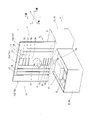
図1~図6に示すように、前記保護装置10は、保護体部11、4つのパンタグラフ機構20,21,22,23、溝35aを備えた構造体としての溝体35、及びクーラント供給装置40などから構成される。そして、前記保護体部11は、コラム3及び主軸頭5の移動路を外部、即ち、本例では加工領域から隔てるように、第1ベッド2a上に立設されている。尚、言うまでもないことであるが、本例における加工領域は、前記テーブル7が設けられた前記第2ベッド2bより上側の領域である。
As shown in FIGS. 1 to 6, the protective device 10 includes a protective body portion 11, four pantograph mechanisms 20, 21, 22, 23, a groove body 35 as a structure having a groove 35a, and a coolant supply device. It is composed of 40 and the like. The protective body portion 11 is erected on the first bed 2a so as to separate the moving paths of the column 3 and the spindle head 5 from the outside, that is, in this example, the processing region. Needless to say, the processing region in this example is the region above the second bed 2b on which the table 7 is provided.
図1及び図3に示すように、前記保護体部11は、門型をした固定板12、この門型の固定板12の内側に設けられるそれぞれ矩形をした保持板13、スライド板14,15,16,17、並びに固定板25及びスライド板26,27,28,29,30,31などから構成される。前記固定板12は、所定の間隔を空けて立設される2つの垂直部12a,12cと、この垂直部12a,12cを連結するようにこれらの上部に設けられた水平部12bとから構成される。
As shown in FIGS. 1 and 3, the protective body portion 11 includes a gate-shaped fixing plate 12, a rectangular holding plate 13 provided inside the gate-shaped fixing plate 12, and slide plates 14, 15 respectively. , 16, 17, and the fixing plate 25 and the slide plate 26, 27, 28, 29, 30, 31, and the like. The fixing plate 12 is composed of two vertical portions 12a and 12c erected at predetermined intervals and a horizontal portion 12b provided on the upper portions of the vertical portions 12a and 12c so as to connect the vertical portions 12a and 12c. Ru.
前記保持板13は、主軸頭5が挿通されるように内側が矩形にくり貫かれた枠状の板材であり、この枠内に、前記固定板25及びスライド板26,27,28,29,30,31が設けられている。また、門型をした固定板12と保持板13との間には左右に空間が形成されており、右側の空間には前記スライド板14,15が配設され、左側の空間にはスライド板16,17が配設されている。
The holding plate 13 is a frame-shaped plate material whose inside is hollowed out so that the spindle head 5 is inserted, and the fixing plate 25 and the slide plates 26, 27, 28, 29, are contained in the frame. 30 and 31 are provided. Further, spaces are formed on the left and right between the gate-shaped fixing plate 12 and the holding plate 13, the slide plates 14 and 15 are arranged in the space on the right side, and the slide plates are arranged in the space on the left side. 16 and 17 are arranged.
前記スライド板14,15は、X軸方向にスライド可能に前記固定板12の水平部12bに吊下されており、第2ベッド2b側から第1ベッド2a側に向けた方向において、固定板12の垂直部12a、スライド板15、スライド板14、保持板13の順に配置されている。そして、スライド板14,15は、相互間での摺動を伴いながら、相互に重なり合うようにスライドし、また、スライド板14は保持板13との間で摺動を伴いながら重なり合うようにスライドし、同様に、スライド板15は固定板12の垂直部12aとの間で摺動を伴いながら重なり合うようにスライドする。
The slide plates 14 and 15 are suspended from the horizontal portion 12b of the fixing plate 12 so as to be slidable in the X-axis direction, and the fixing plate 12 is oriented from the second bed 2b side to the first bed 2a side. The vertical portion 12a, the slide plate 15, the slide plate 14, and the holding plate 13 are arranged in this order. Then, the slide plates 14 and 15 slide so as to overlap each other while being slid between each other, and the slide plate 14 slides so as to be overlapped with the holding plate 13 while being slid. Similarly, the slide plate 15 slides so as to overlap with the vertical portion 12a of the fixing plate 12 while sliding.
また、固定板12の垂直部12a、スライド板15,14及び保持板13は、上下に設けられた2つのパンタグラフ機構20,21によって連結されており、このパンタグラフ機構20,21の作用によって、保持板13及びスライド板14,15は同調してX軸方向に移動し、互いに重なり合う方向にスライドすることで収縮し、互いに引き伸ばされる方向にスライドすることで展伸する。
Further, the vertical portions 12a, the slide plates 15, 14 and the holding plates 13 of the fixing plate 12 are connected by two pantograph mechanisms 20 and 21 provided above and below, and are held by the action of the pantograph mechanisms 20 and 21. The plate 13 and the slide plates 14 and 15 move in the X-axis direction in synchronization with each other, contract by sliding in the direction of overlapping with each other, and expand by sliding in the direction of being stretched by each other.
同様に、前記スライド板16,17は、X軸方向にスライド可能に前記固定板12の水平部12bに吊下されており、第2ベッド2b側から第1ベッド2a側に向けた方向において、固定板12の垂直部12c、スライド板17、スライド板16、保持板13の順に配置されている。そして、スライド板16,17は、相互間での摺動を伴いながら、相互に重なり合うようにスライドし、また、スライド板16は保持板13との間で摺動を伴いながら重なり合うようにスライドし、同様に、スライド板17は固定板12の垂直部12cとの間で摺動を伴いながら重なり合うようにスライドする。
Similarly, the slide plates 16 and 17 are suspended from the horizontal portion 12b of the fixing plate 12 so as to be slidable in the X-axis direction, and in the direction from the second bed 2b side to the first bed 2a side. The vertical portion 12c of the fixing plate 12, the slide plate 17, the slide plate 16, and the holding plate 13 are arranged in this order. Then, the slide plates 16 and 17 slide so as to overlap each other while being slid between each other, and the slide plate 16 slides so as to be overlapped with the holding plate 13 while being slid. Similarly, the slide plate 17 slides so as to overlap with the vertical portion 12c of the fixed plate 12 while sliding.
また、固定板12の垂直部12c、スライド板17,16及び保持板13は、上下に設けられた2つのパンタグラフ機構22,23によって連結されており、このパンタグラフ機構22,23の作用によって、保持板13及びスライド板16,17は同調してX軸方向に移動し、互いに重なり合う方向にスライドすることで収縮し、互いに引き伸ばされる方向にスライドすることで展伸する。
Further, the vertical portions 12c of the fixing plate 12, the slide plates 17, 16 and the holding plate 13 are connected by two pantograph mechanisms 22 and 23 provided above and below, and are held by the action of the pantograph mechanisms 22 and 23. The plate 13 and the slide plates 16 and 17 move in the X-axis direction in synchronization with each other, contract by sliding in the direction of overlapping with each other, and expand by sliding in the direction of being stretched by each other.
斯くして、コラム3及び主軸頭5がX軸プラス方向に移動する場合には、保持板13と固定板12の垂直部12aとの間が展伸され、保持板13と固定板12の垂直部12cとの間は収縮される(図4参照)。一方、コラム3及び主軸頭5がX軸マイナス方向に移動する場合には、保持板13と固定板12の垂直部12aとの間が収縮され、保持板13と固定板12の垂直部12cとの間は展伸される。
Thus, when the column 3 and the spindle head 5 move in the plus direction of the X-axis, the space between the holding plate 13 and the vertical portion 12a of the fixing plate 12 is extended, and the holding plate 13 and the fixing plate 12 are vertical. It is contracted to and from the portion 12c (see FIG. 4). On the other hand, when the column 3 and the spindle head 5 move in the minus direction on the X-axis, the space between the holding plate 13 and the vertical portion 12a of the fixing plate 12 is contracted, and the holding plate 13 and the vertical portion 12c of the fixing plate 12 are contracted. It is extended during the period.
前記固定板25は前記主軸頭5が挿通された状態で当該主軸頭5に固定されている。この固定板25と保持板13との間には上下に空間が形成されており、上側の空間には前記スライド板26,27,28が配設され、下左側の空間にはスライド板29,30,31が配設されている。
The fixing plate 25 is fixed to the spindle head 5 with the spindle head 5 inserted. Spaces are formed above and below between the fixing plate 25 and the holding plate 13, the slide plates 26, 27, 28 are arranged in the upper space, and the slide plates 29, are arranged in the lower left space. 30 and 31 are arranged.
前記スライド板26,27,28は、Y軸方向にスライド可能に配設されており、第2ベッド2b側から第1ベッド2a側に向けた方向において、スライド板26、スライド板27、スライド板28、固定板25の順に配置されている。そして、スライド板26,27は、相互間での摺動を伴いながら、相互に重なり合うようにスライドし、同様に、スライド板27,28は、相互間での摺動を伴いながら、相互に重なり合うようにスライドする。また、スライド板28は固定板25との間で摺動を伴いながら重なり合うようにスライドし、同様に、スライド板26は保持板13との間で摺動を伴いながら重なり合うようにスライドする。
The slide plates 26, 27, and 28 are slidably arranged in the Y-axis direction, and the slide plate 26, the slide plate 27, and the slide plate are arranged in the direction from the second bed 2b side to the first bed 2a side. 28 and the fixing plate 25 are arranged in this order. Then, the slide plates 26 and 27 slide so as to overlap each other while being slid between each other, and similarly, the slide plates 27 and 28 are overlapped with each other while being slid between each other. Slide like. Further, the slide plate 28 slides so as to overlap with the fixing plate 25 while sliding, and similarly, the slide plate 26 slides so as to overlap with the holding plate 13 while sliding.
また、図示は省略するが、固定板25、スライド板28,27,26及び保持板13は、パンタグラフ機構によって連結されており、このパンタグラフ機構の作用によって、固定板25及びスライド板28,27,26は同調してY軸方向に移動し、互いに重なり合う方向にスライドすることで収縮し、互いに引き伸ばされる方向にスライドすることで展伸する。
Although not shown, the fixing plate 25, the slide plates 28, 27, 26 and the holding plate 13 are connected by a pantograph mechanism, and the fixed plate 25 and the slide plates 28, 27, by the action of the pantograph mechanism. 26 moves in the Y-axis direction in synchronization, contracts by sliding in a direction in which they overlap each other, and expands by sliding in a direction in which they are stretched with each other.
同様に、前記スライド板29,30,31は、Y軸方向にスライド可能に配設されており、第2ベッド2b側から第1ベッド2a側に向けた方向において、スライド板29,スライド板30、スライド板31、固定板25の順に配置されている。そして、スライド板29,30は、相互間での摺動を伴いながら、相互に重なり合うようにスライドし、同様に、スライド板30,31は、相互間での摺動を伴いながら、相互に重なり合うようにスライドする。また、スライド板31は固定板25との間で摺動を伴いながら重なり合うようにスライドし、同様に、スライド板29は保持板13との間で摺動を伴いながら重なり合うようにスライドする。
Similarly, the slide plates 29, 30 and 31 are slidably arranged in the Y-axis direction, and the slide plate 29 and the slide plate 30 are arranged in the direction from the second bed 2b side to the first bed 2a side. , The slide plate 31, and the fixing plate 25 are arranged in this order. Then, the slide plates 29 and 30 slide so as to overlap each other while being slid between each other, and similarly, the slide plates 30 and 31 are overlapped with each other while being slid between each other. Slide like. Further, the slide plate 31 slides so as to overlap with the fixing plate 25 while sliding, and similarly, the slide plate 29 slides so as to overlap with the holding plate 13 while sliding.
また、同じく図示を省略しているが、固定板25、スライド板31,30,29及び保持板13は、パンタグラフ機構によって連結されており、このパンタグラフ機構の作用によって、固定板25及びスライド板31,30,29は同調してY軸方向に移動し、互いに重なり合う方向にスライドすることで収縮し、互いに引き伸ばされる方向にスライドすることで展伸する。
Further, although not shown, the fixing plate 25, the slide plates 31, 30, 29 and the holding plate 13 are connected by a pantograph mechanism, and the fixing plate 25 and the slide plate 31 are connected by the action of the pantograph mechanism. , 30, 29 move in the Y-axis direction in synchronization, contract by sliding in the direction of overlapping with each other, and expand by sliding in the direction of being stretched with each other.
斯くして、主軸頭5がY軸プラス方向に移動する場合には、スライド板26,27,28は収縮され、スライド板20,30,31は展伸される。一方、主軸頭5がY軸マイナス方向に移動する場合には、スライド板26,27,28は展伸され、スライド板20,30,31は収縮される。
Thus, when the spindle head 5 moves in the Y-axis plus direction, the slide plates 26, 27, 28 are contracted and the slide plates 20, 30, 31 are extended. On the other hand, when the spindle head 5 moves in the negative direction of the Y axis, the slide plates 26, 27, 28 are extended and the slide plates 20, 30, 31 are contracted.
前記溝体35は、上部が開口し、且つ流路を形成する溝35aを備えた構造体であり、その横断面形状はほぼU字形状を有している。そして、この溝体35は、前記固定板12の垂直部12a,12c、並びに前記保持板13及び前記スライド板14,15,16,17の下端部が、上部開口から前記溝35a内に入り込んだ状態となるように配設されるとともに、その両端部がそれぞれ前記固定板12の垂直部12a,12cの下端部に連結された状態となっている。
The groove body 35 is a structure having a groove 35a having an open upper portion and forming a flow path, and the cross-sectional shape thereof has a substantially U-shape. Then, in the groove body 35, the vertical portions 12a and 12c of the fixing plate 12, and the lower ends of the holding plate 13 and the slide plates 14, 15, 16 and 17 have entered the groove 35a from the upper opening. It is arranged so as to be in a state, and both ends thereof are connected to the lower ends of the vertical portions 12a and 12c of the fixing plate 12, respectively.
また、溝体36の両端部には、溝35aを堰き止めるための側壁36,37が設けられている。この側壁36,37は、それぞれ上部が鉛直部36a,37aを成し、下部が相手方に向けて下り傾斜となった傾斜部36b,37bを成している。そして、各鉛直部36a,37aには、ノズル体38,39が当該鉛直部36a,37aをそれぞれ貫通し、その吐出口が下方に向いた状態で前記溝35内に位置するように固設されている。また、各ノズル体38,39には、工作機械1の加工領域内にクーラントを供給するクーラント供給装置40から加圧されたクーラントが供給される。
Further, side walls 36 and 37 for blocking the groove 35a are provided at both ends of the groove body 36. The upper portions of the side walls 36 and 37 form vertical portions 36a and 37a, respectively, and the lower portions form inclined portions 36b and 37b that are inclined downward toward the other party. Then, in each of the vertical portions 36a and 37a, the nozzle bodies 38 and 39 penetrate the vertical portions 36a and 37a, respectively, and are fixed so as to be located in the groove 35 with the discharge port facing downward. ing. Further, the coolant supplied from the coolant supply device 40, which supplies the coolant into the machining region of the machine tool 1, is supplied to the nozzle bodies 38 and 39.
また、前記溝体35の底面には、その長手方向中央付近に2つの排出口35b,35cが形成されており、この排出口35b,35cは、適宜流路を介して第1ベッド2aの正面に開口する流出口45に連通している。
Further, on the bottom surface of the groove body 35, two discharge ports 35b and 35c are formed near the center in the longitudinal direction thereof, and the discharge ports 35b and 35c are appropriately placed in front of the first bed 2a via a flow path. It communicates with the outlet 45 that opens in.
斯くして、前記クーラント供給装置40から前記ノズル体38,39に供給されたクーラントは、当該ノズル体38,39の吐出口から、その下方に位置する前記側壁36,37の傾斜部36b,37bに向けて吐出され、当該傾斜部36b,37bに沿って流通した後、溝35内を流通して前記排出口35b,35cから排出され、前記第1ベッド2aの正面に開口した流出口45から第2ベッド2bに流出される。
Thus, the coolant supplied from the coolant supply device 40 to the nozzle bodies 38, 39 is the inclined portions 36b, 37b of the side walls 36, 37 located below the discharge port of the nozzle bodies 38, 39. After being discharged toward, and circulated along the inclined portions 36b and 37b, it circulates in the groove 35 and is discharged from the discharge ports 35b and 35c, and is discharged from the outlet 45 opened in front of the first bed 2a. It is discharged to the second bed 2b.
尚、第2ベッド2bには、加工によって生じた加工屑や、加工領域内に供給されたクーラントを回収するための開口が形成されており、前記流出口45から第2ベッド2bに流出したクーラントは、この開口を通して、前記クーラント供給装置40に還流される。
The second bed 2b is formed with an opening for collecting the processing waste generated by processing and the coolant supplied into the processing region, and the coolant flowing out from the outlet 45 to the second bed 2b. Is refluxed to the coolant supply device 40 through this opening.
以上の構成を備えた本例の工作機械1によれば、前記保護装置10の保護体部11により、コラム3及び主軸頭5の移動路が加工領域から隔てられているので、当該加工領域内において、加工によって切屑が生じたり、或いは、加工時に供給されたクーラントが飛散したとしても、前記保護体部11により、当該切屑やクーラントがコラム3及び主軸頭5の移動路内に侵入するのが防止される。
According to the machine tool 1 of this example having the above configuration, since the moving paths of the column 3 and the spindle head 5 are separated from the machining area by the protective body portion 11 of the protection device 10, the inside of the machining area is provided. In the above, even if chips are generated by processing or the coolant supplied during processing is scattered, the chips and coolant can enter the moving paths of the column 3 and the spindle head 5 by the protective body portion 11. Be prevented.
また、前記主軸頭5がX軸方向に移動する場合、これに伴って、保持板13と固定板12の垂直部12aとの間、及び保持板13と固定板12の垂直部12cとの間が伸縮されるが、この伸縮部に形成される摺接部分、具体的には、保持板13とスライド板14との間、スライド板14とスライド板15との間、固定板12の垂直部12aとスライド板15との間、保持板13とスライド板16との間、スライド板16とスライド板17との間、固定板12の垂直部12cとスライド板17との間に形成される摺接部分から、それぞれの裏側に、比較的小さな切屑や粉体状の切屑が侵入して、下方に落下することがある。
When the spindle head 5 moves in the X-axis direction, the space between the holding plate 13 and the vertical portion 12a of the fixing plate 12 and the space between the holding plate 13 and the vertical portion 12c of the fixing plate 12 are accompanied by the movement. Is expanded and contracted, but the sliding contact portion formed in this elastic portion, specifically, between the holding plate 13 and the slide plate 14, between the slide plate 14 and the slide plate 15, and the vertical portion of the fixing plate 12. A slide formed between the 12a and the slide plate 15, between the holding plate 13 and the slide plate 16, between the slide plate 16 and the slide plate 17, and between the vertical portion 12c of the fixing plate 12 and the slide plate 17. Relatively small chips or powdery chips may invade the back side of each from the contact portion and fall downward.
本例の保護装置10では、前記固定板12の垂直部12a,12c、並びに前記保持板13及び前記スライド板14,15,16,17の下端部が前記溝35a内に入り込んだ状態となるように溝体35が設けられるとともに、クーラント供給装置40から溝35a内にクーラントが供給され、その両端の側壁36,37部から中央の排出口35b,35cに向けてクーラントが流通するように構成されているので、上記のようにして裏側に侵入して下方に落下した切屑は、溝体35の溝35a内に回収された後、当該溝35a内を流通するクーラントにより押し流されて、前記排出口35b,35cから排出され、この後、前記流出口45を通して第2ベッド2bに流出され、第2ベッド2bに形成された開口を通して適宜回収される。
In the protection device 10 of this example, the vertical portions 12a and 12c of the fixing plate 12, and the lower ends of the holding plate 13 and the slide plates 14, 15, 16 and 17 are in a state of being inserted into the groove 35a. A groove body 35 is provided in the groove 35, and the coolant is supplied into the groove 35a from the coolant supply device 40, and the coolant is configured to flow from the side walls 36 and 37 at both ends toward the central discharge ports 35b and 35c. Therefore, the chips that have entered the back side and fallen downward as described above are collected in the groove 35a of the groove body 35, and then washed away by the coolant circulating in the groove 35a, and the discharge port is said. It is discharged from the 35b and 35c, then flows out to the second bed 2b through the outlet 45, and is appropriately collected through the opening formed in the second bed 2b.
以上により、溝35a内に切屑が堆積するのが防止され、溝35a内に切屑が堆積することによって、前記スライド板14,15,16,17の移動に障害を生じ、延いてはスライド板14,15,16,17が塑性変形する、或いは、この塑性変形に起因してスライド板14,15,16,17が破損するといった事態が生じるのを防止することができる。
As described above, the accumulation of chips in the groove 35a is prevented, and the accumulation of chips in the groove 35a causes an obstacle to the movement of the slide plates 14, 15, 16 and 17, and eventually the slide plate 14 , 15, 16 and 17 may be plastically deformed, or the slide plates 14, 15, 16 and 17 may be prevented from being damaged due to this plastic deformation.
また、本例では、各ノズル体38,39は、その吐出口から下方に向けてクーラントを吐出するように設けられているので、ノズル体38,39から吐出されたクーラントがスライド板14,15,16,17の下端部に衝突するのを抑制することができ、これらとの衝突によってクーラントが周囲に飛散するのを抑制することができる。
Further, in this example, since the nozzle bodies 38 and 39 are provided so as to discharge the coolant downward from the discharge port, the coolant discharged from the nozzle bodies 38 and 39 is the slide plates 14 and 15. It is possible to suppress the collision with the lower end portions of, 16 and 17, and it is possible to suppress the scattering of the coolant to the surroundings due to the collision with these.
また、前記側壁36,37の下部がそれぞれ相手方に向けた下り傾斜の傾斜部36b,37bとなっているので、各ノズル体38,39の吐出口から吐出されたクーラントは、この傾斜部36b,37bの傾斜面に案内されて流下し、溝35aの底部に沿って流通する。したがって、ノズル体38,39から吐出された液体は、乱れを生じたり、周囲に飛散することなく、溝35a内を滑らかに流通する。
Further, since the lower portions of the side walls 36 and 37 are inclined portions 36b and 37b having a downward inclination toward the other side, the coolant discharged from the discharge ports of the nozzle bodies 38 and 39 is the inclined portions 36b. Guided by the inclined surface of 37b, it flows down and flows along the bottom of the groove 35a. Therefore, the liquid discharged from the nozzle bodies 38 and 39 smoothly flows in the groove 35a without causing turbulence or scattering to the surroundings.
また、本例では、前記構体35の横断面形状をU字状としているので、クーラントを溝35aの底部に沿って流通させることができ、これによっても、クーラントがスライド板14,15,16,17の下端部に衝突するのを抑制することができ、これらとの衝突によってクーラントが周囲に飛散するのを抑制することができる。
Further, in this example, since the cross-sectional shape of the structure 35 is U-shaped, the coolant can be circulated along the bottom of the groove 35a, and the coolant can also be distributed along the slide plates 14, 15, 16, and It is possible to suppress the collision with the lower end portion of 17, and it is possible to suppress the coolant from scattering to the surroundings due to the collision with these.
以上、本発明の一実施形態について説明したが、本発明が採り得る具体的な態様は、何ら上例のものに限定されるものではない。
Although one embodiment of the present invention has been described above, the specific embodiments that the present invention can take are not limited to those of the above examples.
例えば、前記側壁36,37の双方にノズル体38,39をそれぞれ設けたが、このような態様に限られるものでは無く、側壁36,37のいずれか一方にノズル体を設けた態様としても良い。この場合、前記溝体35に形成する排出口は、ノズル体を設けない側の側壁の近傍に形成するのが好ましい。
For example, the nozzle bodies 38 and 39 are provided on both of the side walls 36 and 37, respectively, but the present invention is not limited to this aspect, and the nozzle body may be provided on any one of the side walls 36 and 37. .. In this case, it is preferable that the discharge port formed in the groove body 35 is formed in the vicinity of the side wall on the side where the nozzle body is not provided.
また、上例では、前記ノズル体38,39は、その吐出口が下方に向けてクーラントを吐出するように構成されているが、このような態様に限られるものでは無く、クーラントがスライド板14,15,16,17の下端部に直接衝突しない範囲で、相手方に向けて斜め下方にクーラントを吐出するように構成されていても良い。
Further, in the above example, the nozzle bodies 38 and 39 are configured such that the discharge port thereof discharges the coolant downward, but the present invention is not limited to such an embodiment, and the coolant is the slide plate 14. , 15, 16 and 17 may be configured to discharge the coolant diagonally downward toward the other party within a range that does not directly collide with the lower ends.
また、上例では、前記側壁36,37を、上部の鉛直部36a,37a及び下部の傾斜部36b,37bから構成したが、このような態様に限られるものでは無く、クーラントの流れに支障がなければ、鉛直部36a,37aのみとしても良く、或いは傾斜部36b,37bのみとしても良い。また、傾斜部36b,37bは平面に限られるものでは無く、所定の曲率で湾曲させた湾曲面としても良い。
Further, in the above example, the side walls 36 and 37 are composed of the upper vertical portions 36a and 37a and the lower inclined portions 36b and 37b, but the present invention is not limited to such an embodiment and hinders the flow of coolant. If not, only the vertical portions 36a and 37a may be used, or only the inclined portions 36b and 37b may be used. Further, the inclined portions 36b and 37b are not limited to a flat surface, and may be a curved surface curved with a predetermined curvature.
また、上例では、前記固定板12の垂直部12a,12c、並びに前記保持板13及び前記スライド板14,15,16,17の下端部が前記溝35a内に入り込んだ状態となるように溝体35を配設したが、これに限られるものでは無く、溝体35を固定板12の垂直部12a,12c、保持板13及びスライド板14,15,16,17の下方に配設した態様としても良い。このようにすれば、前記ノズル体38,39から水平方向にクーラントを吐出させても、当該クーラントがスライド板14,15,16,17の下端部と衝突するのを回避することができる。
Further, in the above example, the vertical portions 12a and 12c of the fixing plate 12, and the lower ends of the holding plate 13 and the slide plates 14, 15, 16 and 17 are grooved so as to be in the groove 35a. The body 35 is arranged, but the present invention is not limited to this, and the groove body 35 is arranged below the vertical portions 12a and 12c of the fixing plate 12, the holding plate 13 and the slide plates 14, 15, 16 and 17. May be. By doing so, even if the coolant is discharged in the horizontal direction from the nozzle bodies 38 and 39, it is possible to prevent the coolant from colliding with the lower ends of the slide plates 14, 15, 16 and 17.
また、上例では、前記構体35の横断面形状をU字状としたが、これに限られるものでは無く、横断面形状をV字状としても良い。このようにしても同様の効果が奏される。
Further, in the above example, the cross-sectional shape of the structure 35 is U-shaped, but the present invention is not limited to this, and the cross-sectional shape may be V-shaped. Even in this way, the same effect is achieved.
また、本例では、保護装置10を横型のマシニングセンタに適用したが、当該保護装置10を適用可能な工作機械は、これに限定されるものでは無く、当然のことながら、特段の不都合を生じない限り、他のあらゆる工作機械に対しても適用することができる。
Further, in this example, the protective device 10 is applied to a horizontal machining center, but the machine tool to which the protective device 10 can be applied is not limited to this, and as a matter of course, no particular inconvenience occurs. As long as it can be applied to any other machine tool.
繰り返しになるが、上述の実施形態の説明は、すべての点で例示であって、制限的なものではない。当業者にとって変形および変更が適宜可能である。本発明の範囲は、上述の実施形態ではなく、特許請求の範囲によって示される。さらに、本発明の範囲には、特許請求の範囲内と均等の範囲内での実施形態からの変更が含まれる。
Again, the above description of the embodiment is exemplary in all respects and is not restrictive. Modifications and changes can be made as appropriate for those skilled in the art. The scope of the invention is indicated by the claims, not by the embodiments described above. Further, the scope of the present invention includes modifications from the embodiments within the scope of the claims and within the scope of the claims.
1 工作機械
2 ベッド
3 コラム
5 主軸頭
6 主軸
10 保護装置
11 保護体部
12 固定板
13 保持板
14,15,16,17 スライド板
20,1,22,23 パンタグラフ機構
25 固定板
26,27,28,29,30,31 スライド板
35 溝体
35a 溝
36,37 側壁
36a,37a 鉛直部
36b,37b 傾斜部
38,39 ノズル体
40 クーラント供給装置
1Machine tool 2 Bed 3 Column 5 Spindle head 6 Spindle 10 Protective device 11 Protective body 12 Fixing plate 13 Holding plate 14, 15, 16, 17 Slide plate 20, 1, 22, 23 Pantograph mechanism 25 Fixing plate 26, 27, 28, 29, 30, 31 Slide plate 35 Groove 35a Groove 36, 37 Side wall 36a, 37a Vertical part 36b, 37b Inclined part 38, 39 Nozzle body 40 Coolant supply device
2 ベッド
3 コラム
5 主軸頭
6 主軸
10 保護装置
11 保護体部
12 固定板
13 保持板
14,15,16,17 スライド板
20,1,22,23 パンタグラフ機構
25 固定板
26,27,28,29,30,31 スライド板
35 溝体
35a 溝
36,37 側壁
36a,37a 鉛直部
36b,37b 傾斜部
38,39 ノズル体
40 クーラント供給装置
1
Claims (5)
- 所定方向に移動する移動体の移動路を外部から隔てるように、且つ前記移動体の移動方向に順次連続するように接続された複数の保護体を備え、一方端側に配設される保護体は保護すべき領域の所定端部に連結されるとともに、他方端側に配設される保護体は前記移動体に連結され、複数の保護体は全体として前記移動体の移動によって伸縮するように構成された保護装置において、
上部が開口し、且つ流路を形成する溝を備えた構造体であって、前記各保護体の下端面との間に所定の間隔を有するように該保護体の下方に、又は該保護体の下端部が上部開口から前記溝内に入り込んだ状態となるように、該複数の保護体に沿って配設された構造体と、
前記構造体に接続され、該構造体の溝内に液体を吐出するノズルと、
前記ノズルに加圧液体を供給する液体供給源とを設けて構成したことを特徴とする保護装置。 A protective body provided on one end side of a plurality of protective bodies connected so as to separate the moving path of the moving body moving in a predetermined direction from the outside and sequentially continuous in the moving direction of the moving body. Is connected to a predetermined end of the area to be protected, the protecting body disposed on the other end side is connected to the moving body, and the plurality of protecting bodies as a whole expands and contracts due to the movement of the moving body. In the configured protecting device
A structure having an open upper portion and a groove forming a flow path, and below the protective body or the protective body so as to have a predetermined distance from the lower end surface of each protective body. A structure arranged along the plurality of protective bodies so that the lower end portion of the sword is inserted into the groove through the upper opening.
A nozzle connected to the structure and ejecting a liquid into the groove of the structure,
A protective device characterized in that the nozzle is provided with a liquid supply source for supplying a pressurized liquid. - 前記構造体は、展伸された状態にある前記各保護体の下面全域に対応するように、該保護体に沿って配設されるとともに、少なくとも前記一方端方向における端部に溝を堰き止める側壁が設けられ、
前記ノズルは、前記構造体の側壁に設けられていることを特徴とする請求項1記載の保護装置。 The structure is arranged along the protective body so as to correspond to the entire lower surface of each of the protected bodies in a stretched state, and at least blocks a groove at an end portion in one end direction. A side wall is provided,
The protective device according to claim 1, wherein the nozzle is provided on a side wall of the structure. - 前記側壁は、少なくとも一部が前記他方端側に向けた下り傾斜面となっていることを特徴とする請求項2記載の保護装置。 The protective device according to claim 2, wherein at least a part of the side wall is a downwardly inclined surface toward the other end side.
- 前記ノズルは、下方に向けて液体を吐出するように設けられていることを特徴とする請求項1から3のいずれか1項に記載の保護装置。 The protective device according to any one of claims 1 to 3, wherein the nozzle is provided so as to discharge a liquid downward.
- 前記構造体の溝は、その横断面形状がU字状又はV字状であることを特徴とする請求項1から4のいずれか1項に記載の保護装置。
The protective device according to any one of claims 1 to 4, wherein the groove of the structure has a U-shaped or V-shaped cross-sectional shape.
Priority Applications (3)
| Application Number | Priority Date | Filing Date | Title |
|---|---|---|---|
| US18/028,275 US20230271290A1 (en) | 2020-10-01 | 2021-06-22 | Protective device |
| CN202180066225.5A CN116323095A (en) | 2020-10-01 | 2021-06-22 | Protection device |
| EP21874834.1A EP4209303A4 (en) | 2020-10-01 | 2021-06-22 | Protective device |
Applications Claiming Priority (2)
| Application Number | Priority Date | Filing Date | Title |
|---|---|---|---|
| JP2020-166748 | 2020-10-01 | ||
| JP2020166748A JP6804687B1 (en) | 2020-10-01 | 2020-10-01 | Protective device |
Publications (1)
| Publication Number | Publication Date |
|---|---|
| WO2022070530A1 true WO2022070530A1 (en) | 2022-04-07 |
Family
ID=73836048
Family Applications (1)
| Application Number | Title | Priority Date | Filing Date |
|---|---|---|---|
| PCT/JP2021/023528 WO2022070530A1 (en) | 2020-10-01 | 2021-06-22 | Protective device |
Country Status (5)
| Country | Link |
|---|---|
| US (1) | US20230271290A1 (en) |
| EP (1) | EP4209303A4 (en) |
| JP (1) | JP6804687B1 (en) |
| CN (1) | CN116323095A (en) |
| WO (1) | WO2022070530A1 (en) |
Citations (4)
| Publication number | Priority date | Publication date | Assignee | Title |
|---|---|---|---|---|
| JPS6175948U (en) * | 1984-10-25 | 1986-05-22 | ||
| JPH11300573A (en) * | 1998-04-16 | 1999-11-02 | Hookosu Kk | Cover fitting structure of machine tool |
| JP2009241163A (en) | 2008-03-28 | 2009-10-22 | Komatsu Ntc Ltd | Telescopic cover for machine tool |
| JP2018030202A (en) * | 2016-08-25 | 2018-03-01 | ローランドディー.ジー.株式会社 | Processing device and processing method |
Family Cites Families (3)
| Publication number | Priority date | Publication date | Assignee | Title |
|---|---|---|---|---|
| DE9013621U1 (en) * | 1990-09-28 | 1991-03-14 | Ima-Norte Maschinenfabriken Klessmann Gmbh & Co, 4830 Guetersloh, De | |
| EP0523286A1 (en) * | 1991-07-15 | 1993-01-20 | Emilceramica S.P.A. | Plant for pressing ceramic tiles in general, typically pressure-glazed tiles |
| JP5667225B2 (en) * | 2013-02-21 | 2015-02-12 | ファナック株式会社 | Machine tool with wiper on table to remove chips accumulated on movable cover |
-
2020
- 2020-10-01 JP JP2020166748A patent/JP6804687B1/en active Active
-
2021
- 2021-06-22 CN CN202180066225.5A patent/CN116323095A/en active Pending
- 2021-06-22 US US18/028,275 patent/US20230271290A1/en active Pending
- 2021-06-22 EP EP21874834.1A patent/EP4209303A4/en active Pending
- 2021-06-22 WO PCT/JP2021/023528 patent/WO2022070530A1/en unknown
Patent Citations (4)
| Publication number | Priority date | Publication date | Assignee | Title |
|---|---|---|---|---|
| JPS6175948U (en) * | 1984-10-25 | 1986-05-22 | ||
| JPH11300573A (en) * | 1998-04-16 | 1999-11-02 | Hookosu Kk | Cover fitting structure of machine tool |
| JP2009241163A (en) | 2008-03-28 | 2009-10-22 | Komatsu Ntc Ltd | Telescopic cover for machine tool |
| JP2018030202A (en) * | 2016-08-25 | 2018-03-01 | ローランドディー.ジー.株式会社 | Processing device and processing method |
Non-Patent Citations (1)
| Title |
|---|
| See also references of EP4209303A4 |
Also Published As
| Publication number | Publication date |
|---|---|
| EP4209303A4 (en) | 2024-01-24 |
| EP4209303A1 (en) | 2023-07-12 |
| JP2022059176A (en) | 2022-04-13 |
| JP6804687B1 (en) | 2020-12-23 |
| CN116323095A (en) | 2023-06-23 |
| US20230271290A1 (en) | 2023-08-31 |
Similar Documents
| Publication | Publication Date | Title |
|---|---|---|
| EP1254740B1 (en) | Machine tool with chip collection means | |
| JP5667225B2 (en) | Machine tool with wiper on table to remove chips accumulated on movable cover | |
| EP2747936B1 (en) | Machine tool | |
| JP5739480B2 (en) | Machine tool having anti-scatter cover | |
| EP2332690A2 (en) | Machine tool | |
| WO2004076122A1 (en) | Column moving type machine tool with shield machining space | |
| CN109909757B (en) | Machine tool | |
| CN100544885C (en) | Lathe | |
| JP6876586B2 (en) | Processing equipment | |
| JP6588015B2 (en) | Industrial machine with foreign matter discharge mechanism | |
| CN104002184A (en) | Machine tool with cover adapted for discharge of chips | |
| US9308612B2 (en) | Machine tool having stopper for preventing chips from entering machine tool | |
| WO2022070530A1 (en) | Protective device | |
| US6877407B2 (en) | Machine tool | |
| EP1982795B1 (en) | Machine tool | |
| US20140238206A1 (en) | Machine tool equipped with movable cover | |
| US5570979A (en) | Telescopic cover for a machine tool | |
| US6835031B2 (en) | Machine tool having an improved cover | |
| JP4710295B2 (en) | Machine Tools | |
| JP2002233926A (en) | Machine tool | |
| KR101106714B1 (en) | chip scattering prevent structure of the horizontal machining center | |
| JP4558436B2 (en) | Vertical machining center | |
| JP2021070087A (en) | Cover device for machine tool | |
| JP4226265B2 (en) | Attachment chip prevention device | |
| JP2023071365A (en) | Machine tool |
Legal Events
| Date | Code | Title | Description |
|---|---|---|---|
| 121 | Ep: the epo has been informed by wipo that ep was designated in this application |
Ref document number: 21874834 Country of ref document: EP Kind code of ref document: A1 |
|
| ENP | Entry into the national phase |
Ref document number: 2021874834 Country of ref document: EP Effective date: 20230403 |
|
| NENP | Non-entry into the national phase |
Ref country code: DE |