JP2014147901A - Microbubble generator and microbubble generating tube structure - Google Patents
Microbubble generator and microbubble generating tube structure Download PDFInfo
- Publication number
- JP2014147901A JP2014147901A JP2013018615A JP2013018615A JP2014147901A JP 2014147901 A JP2014147901 A JP 2014147901A JP 2013018615 A JP2013018615 A JP 2013018615A JP 2013018615 A JP2013018615 A JP 2013018615A JP 2014147901 A JP2014147901 A JP 2014147901A
- Authority
- JP
- Japan
- Prior art keywords
- liquid
- microbubble
- pipe
- cylinder
- generator
- Prior art date
- Legal status (The legal status is an assumption and is not a legal conclusion. Google has not performed a legal analysis and makes no representation as to the accuracy of the status listed.)
- Pending
Links
- 239000007788 liquid Substances 0.000 claims abstract description 171
- XLYOFNOQVPJJNP-UHFFFAOYSA-N water Substances O XLYOFNOQVPJJNP-UHFFFAOYSA-N 0.000 claims description 72
- 239000008399 tap water Substances 0.000 claims description 17
- 235000020679 tap water Nutrition 0.000 claims description 17
- 238000005406 washing Methods 0.000 claims description 15
- 238000002485 combustion reaction Methods 0.000 claims description 11
- 239000000446 fuel Substances 0.000 claims description 9
- 238000007789 sealing Methods 0.000 claims description 4
- 238000012856 packing Methods 0.000 description 21
- 238000004519 manufacturing process Methods 0.000 description 11
- 238000000034 method Methods 0.000 description 8
- 238000004140 cleaning Methods 0.000 description 7
- 239000012530 fluid Substances 0.000 description 6
- 230000000694 effects Effects 0.000 description 5
- 238000010586 diagram Methods 0.000 description 4
- 239000011347 resin Substances 0.000 description 4
- 229920005989 resin Polymers 0.000 description 4
- 238000002347 injection Methods 0.000 description 3
- 239000007924 injection Substances 0.000 description 3
- 238000011160 research Methods 0.000 description 3
- 241000251468 Actinopterygii Species 0.000 description 2
- 239000000919 ceramic Substances 0.000 description 2
- 238000004891 communication Methods 0.000 description 2
- 238000009434 installation Methods 0.000 description 2
- 239000007921 spray Substances 0.000 description 2
- 229910001369 Brass Inorganic materials 0.000 description 1
- 241000237502 Ostreidae Species 0.000 description 1
- 241000237509 Patinopecten sp. Species 0.000 description 1
- 238000012356 Product development Methods 0.000 description 1
- XUIMIQQOPSSXEZ-UHFFFAOYSA-N Silicon Chemical compound [Si] XUIMIQQOPSSXEZ-UHFFFAOYSA-N 0.000 description 1
- 230000003466 anti-cipated effect Effects 0.000 description 1
- 238000009360 aquaculture Methods 0.000 description 1
- 244000144974 aquaculture Species 0.000 description 1
- 239000010951 brass Substances 0.000 description 1
- 238000005266 casting Methods 0.000 description 1
- 230000007423 decrease Effects 0.000 description 1
- 238000009792 diffusion process Methods 0.000 description 1
- 239000000835 fiber Substances 0.000 description 1
- 239000013505 freshwater Substances 0.000 description 1
- 230000003993 interaction Effects 0.000 description 1
- 239000000463 material Substances 0.000 description 1
- 239000002184 metal Substances 0.000 description 1
- 239000002101 nanobubble Substances 0.000 description 1
- 235000020636 oyster Nutrition 0.000 description 1
- 239000011148 porous material Substances 0.000 description 1
- 235000020637 scallop Nutrition 0.000 description 1
- 238000010008 shearing Methods 0.000 description 1
- 229910052710 silicon Inorganic materials 0.000 description 1
- 239000010703 silicon Substances 0.000 description 1
- 230000002463 transducing effect Effects 0.000 description 1
Images


Abstract
Description
本発明は、気体を溶解した液体の流体からマイクロバブルを発生させるマイクロバブル生成器及びそれを備えたマイクロバブル生成管路構造に関する。 The present invention relates to a microbubble generator for generating microbubbles from a liquid fluid in which a gas is dissolved, and a microbubble generating pipeline structure including the microbubble generator.
マイクロバブルについての研究は、1985年頃からスタートした。マイクロバブルは、新しい技術分野であるため、解明されていない点も多い。現在、マイクロバブルについて以下の2つの現象が知られている。 Research on microbubbles started around 1985. Since microbubbles are a new technical field, there are many unexplained points. Currently, the following two phenomena are known for microbubbles.
一つは、マイクロバブルのサイズが小さいことから繊維や毛穴などの奥まで入り込み易い浸透現象である。もう一つは、圧壊である。圧壊は、マイクロバブルが水中に吐出されることで、水中の水圧に押しつぶされ、さらに小さなナノバブルとなり、やがて破壊される現象である。この圧壊が起きる時に、時速約400キロ前後の超音波が発生し、5500度近い高熱を発すると言われている。そして、この2つの現象の相互作用により、汚れなどが取れやすくなると言われている。 One is a permeation phenomenon in which the microbubbles are small in size, so that they can easily penetrate into fibers, pores, and the like. Another is crushing. Crushing is a phenomenon in which microbubbles are discharged into the water and are crushed by the water pressure in the water to become smaller nanobubbles that are eventually destroyed. It is said that when this crushing occurs, an ultrasonic wave of about 400 km / h is generated and a high heat of nearly 5500 degrees is generated. And it is said that dirt and the like are easily removed by the interaction of these two phenomena.
その他の具体的利用例として、水産分野においては、水中にマイクロバブルを発生させることで淡水魚と海水魚を同時に生育させる事例、カキの赤潮被害を防止した事例、ホタテの養殖効率を向上させた事例などが報告されている。 As other specific use cases, in the fisheries field, examples of growing freshwater fish and saltwater fish simultaneously by generating microbubbles in water, examples of preventing oyster red tide damage, and examples of improving scallop aquaculture efficiency Etc. have been reported.
また、船舶分野においては、マイクロバブルを船底に流して船の抵抗を軽減させ、船のスピードを上げる研究がある。また、自動車関連分野においては、内燃機関(エンジン)にマイクロバブル生成器を通して、空気を含んだ混合燃料を噴射させることで、燃焼効率の改善を行う技術も研究されている。 In the ship field, there is a research to reduce the resistance of the ship by flowing microbubbles to the bottom of the ship and increase the speed of the ship. In the field of automobiles, a technique for improving combustion efficiency by injecting a mixed fuel containing air through an internal combustion engine (engine) through a microbubble generator has been studied.
また、大気中の空気を取り込み、マイクロバブルを発生させる装置を付けたシャワーヘッドなどが販売されている。さらに、浴槽用の循環式マイクロバブル発生装置なども販売されている。 In addition, shower heads with devices that take in air from the atmosphere and generate microbubbles are on the market. Furthermore, circulating microbubble generators for bathtubs are also sold.
以上のように、マイクロバブルについての利用、研究は、広範な技術分野で行われている。 As described above, utilization and research on microbubbles are performed in a wide range of technical fields.
ここで、マイクロバブルを発生させる手段として、高速せん断方式、加圧圧壊方式、キャビテーション方式など、6種類ほどが知られている。その多くが、アスピレータ方式などで、外部から空気を吸引している。或いは、強制注入している。 Here, as a means for generating microbubbles, about six types such as a high-speed shearing method, a pressure crushing method, and a cavitation method are known. Many of them draw air from the outside by an aspirator method or the like. Or forced injection.
他方、特許文献1には、外部から空気を吸入することなく、溶存空気からマイクバブルを発生させる、キャビテーション方式のマイクロバブル発生装置が公開されている。 On the other hand, Patent Document 1 discloses a cavitation-type microbubble generator that generates microphone bubbles from dissolved air without inhaling air from the outside.
特許文献1のマイクロバブル発生装置は、高圧ポンプによる旋回流を必要としない簡単な構造で、高速の水流が、狭い間隔で配置した複数個のノズルを通過する際に生じるキャビテーションを利用して、溶存空気によるマイクロバブルを発生させるものであって、(a)入口2eから出口2fに向かってその中心軸に直交する断面積を漸減する通水用入口側の第1ノズル3と、(b)入口側の第1ノズル3との間に連通路8を介して連続して配設され、入口4eから出口4fに向かってその中心軸に直交する断面積を漸増する通水用出口側の第2ノズル4と、(c)前記連通路8にのみ開口した側室8bとを有することを特徴とするものである。
The microbubble generator of Patent Document 1 has a simple structure that does not require a swirling flow by a high-pressure pump, and uses cavitation that occurs when a high-speed water flow passes through a plurality of nozzles arranged at narrow intervals, (A) a
しかしながら、マイクロバブル生成器を既存の配管への簡易な配置する手段、既存の液流体を用いた具体的実用例については、十分な提案がなされていない。例えば、特許文献2には、シャワーヘッドにベンチュリー管1を内蔵させた、マイクロバブルを発生させるシャワーヘッドが開示されている。しかし、ベンチュリー管1は、シャワーヘッド内部に既存品では通常存在しない環状の突起部にゴムパッキン7を係止して、ベンチュリー管1を係止し、止水している。したがって、当該発明に特化した特注(内部環状突起を備える)のシャワーヘッドが必要である。
However, sufficient proposals have not been made for a means for simply arranging the microbubble generator in an existing pipe and a specific practical example using an existing liquid fluid. For example,
そこで、本発明は、液体を被送液箇所に流す既存の送液管に簡易に配置することができるマイクロバブル生成器、及び配管にマイクロバブル生成器を備えた具体的なマイクロバブル生成管路構造を提供することを目的とするものである。 Therefore, the present invention provides a microbubble generator that can be easily arranged in an existing liquid supply pipe that allows liquid to flow to a liquid supply location, and a specific microbubble generation pipe that includes a microbubble generator in a pipe. The purpose is to provide a structure.
マイクロバブルの効果としては、ミクロの気泡による洗浄効果とともに、マイクロバブルが圧壊する時にだす超音波と高熱よる洗浄効果がある。この効果を洗濯機や食洗機、小便器などの給水経路に組み込むことで洗浄力を高めようと考えた。 As the effect of microbubbles, there are a cleaning effect by ultrasonic waves and high heat generated when the microbubbles are crushed, as well as a cleaning effect by microbubbles. We thought to improve the cleaning power by incorporating this effect into the water supply channels of washing machines, dishwashers and urinals.
その際の条件として一般的な水道水の給水圧力0.1MPa程度の圧力で、かつ、一般に配管されている水道水の給水管の管径で、さらに外部から空気を取り込まずに、水道水の中に含まれている含有空気をマイクロバブル化できる管路形状とその配置方法を検討した。そして、既存の送液管に簡易に導入する方法を検討した。 In this case, the tap water supply pressure is about 0.1 MPa as a general tap water pressure, and the pipe diameter of the tap water supply pipe that is generally piped without taking in air from the outside. The shape of the pipe and the arrangement method that can make the contained air contained in the microbubbles were examined. And the method of introduce | transducing to the existing liquid feeding tube simply was examined.
そして、本発明は、上記の課題を解決するために、
(1)
気体を溶解した液体からマイクロバブルを生成するマイクロバブル生成器であって、
外周に溝が穿設され内部に前記液体を通しマイクロバブルを生成するマイクロバブル生成路を備える筒と、前記溝に嵌められ弾性を備えるOリングと、からなり、
前記液体を被送液場所に流す送液管内に配置され、前記Oリングで前記送液管と前記筒との間をシールすることを特徴とするマイクロバブル生成器の構成とした。
(2)
被送液場所にマイクロバブル混合液体を供給する管路構造であって、
被送液場所に液体を流す送液管と、前記送液管内に配置され、前記Oリングで前記送液管と前記筒との間をシールする (1)に記載のマイクロバブル生成器と、からなることを特徴とするマイクロバブル生成管路構造の構成とした。
(3)
気体を溶解した液体からマイクロバブルを生成するマイクロバブル生成器であって、
外周に溝が穿設され一方の端部にフランジを設け内部に前記液体を通しマイクロバブルを生成するマイクロバブル生成路を備える筒と、前記溝に嵌められ弾性を備えるOリングと、からなり、
前記液体を被送液場所に流す送液管の端部に前記フランジで係止されるとともに、前記送液管と前記筒との間を前記Oリングでシールすることを特徴とするマイクロバブル生成器の構成とした。
(4)
被送液場所にマイクロバブル混合液体を供給する管路構造であって、
前記液体が水道水、前記被送液場所が水洗便器、前記送液管が給水管であり、前記水洗便器に前記水道水を流す前記給水管と、前記給水管の端部に前記フランジで係止されるとともに前記給水管と前記筒との間を前記Oリングでシールする(3)に記載のマイクロバブル生成器と、からなることを特徴とするマイクロバブル生成管路構造の構成とした。
(5)
気体を溶解した液体からマイクロバブルを生成するマイクロバブル生成器であって、
前記液体を被送液場所に流す送液管の端部間に螺合し内部に第二内ネジ部を備えるジョイント管と、一方の端部の外周に前記第二内ネジ部に螺合するネジ部を備え前記ネジ部側の端部にフランジを設け内部に前記液体を通しマイクロバブルを生成するマイクロバブル生成路を備える筒と、からなり、前記ジョイント管と前記筒との間を前記第二内ネジ部とネジ部との螺合でシールすることを特徴とするマイクロバブル生成器の構成とした。
(6)
被送液場所にマイクロバブル混合液体を供給する管路構造であって、
被送液場所に液体を流す送液管と、前記送液管の端部間に前記ジョイント管が螺合するとともに前記ジョイント管と前記筒との間を前記第二内ネジ部とネジ部の螺合でシールする(5)に記載のマイクロバブル生成器と、からなることを特徴とするマイクロバブル生成管路構造の構成とした。
(7)
前記マイクロバブル生成路が、前記液体の入口側端部から中心部にいくにしたがって内径が徐々に狭まる第一流路と、前記第一流路に接続する第二流路と、前記第二流路に接続し前記液体の出口側他端に向け内径が徐々に広がる第三流路と、からなることを特徴とする(1)、(3)、又は(5)の何れかに記載のマイクロバブル生成器の構成とした。
(8)
前記気体を溶解した液体が、空気を自然溶解している水道水であることを特徴とする(2)又は(6)に記載のマイクロバブル生成管路構造の構成とした。
(9)
前記被送液場所が、洗濯機内部又は食洗機内部であることを特徴とする(8)に記載のマイクロバブル生成管路構造の構成とした。
(10)
(9)に記載のマイクロバブル生成管路構造を備えたことを特徴とする洗濯機の構成とした。
(11)
(9)に記載のマイクロバブル管路構造を備えたことを特徴とする食器洗浄器の構成とした。
(12)
前記液体が液体燃料であり、前記被送液場所が内燃機関内部であることを特徴とする(2)又は(6)に記載のマイクロバブル生成管路構造の構成とした。
(13)
(12)に記載のマイクロバブル生成管路構造を備えたことを特徴とするオートモービルの構成とした。
And in order to solve said subject, this invention
(1)
A microbubble generator that generates microbubbles from a gas-dissolved liquid,
A cylinder having a microbubble generating path for generating a microbubble through the liquid and having a groove formed in the outer periphery, and an O-ring fitted in the groove and having elasticity,
The microbubble generator has a configuration in which the liquid is disposed in a liquid feeding pipe that flows to a liquid feeding place, and the space between the liquid feeding pipe and the cylinder is sealed by the O-ring.
(2)
A pipe structure for supplying a microbubble mixed liquid to a liquid receiving place,
A liquid-feeding tube for flowing a liquid to a liquid-feeding place, a microbubble generator according to (1), wherein the microbubble generator is disposed in the liquid-feeding tube and seals between the liquid-feeding tube and the cylinder with the O-ring; It was set as the structure of the microbubble production | generation pipeline structure characterized by consisting of.
(3)
A microbubble generator that generates microbubbles from a gas-dissolved liquid,
A cylinder having a microbubble generation path for generating a microbubble through the liquid inside by providing a flange at one end and providing a flange at one end, and an O-ring fitted in the groove and having elasticity,
Microbubble generation characterized in that it is locked by the flange to the end of a liquid feed pipe that causes the liquid to flow to a liquid feed location, and the O-ring is sealed between the liquid feed pipe and the cylinder The configuration of the vessel.
(4)
A pipe structure for supplying a microbubble mixed liquid to a liquid receiving place,
The liquid is tap water, the liquid delivery place is a flush toilet, the liquid feed pipe is a water supply pipe, the water supply pipe for flowing the tap water to the flush toilet, and the flange at the end of the water supply pipe The micro-bubble generating pipe line structure is characterized by comprising the micro-bubble generator described in (3) which is stopped and sealed between the water supply pipe and the cylinder with the O-ring.
(5)
A microbubble generator that generates microbubbles from a gas-dissolved liquid,
A joint pipe that is screwed between ends of a liquid feeding pipe that flows the liquid to a liquid feeding place and has a second internal thread inside, and is screwed to the second internal thread on the outer periphery of one end. And a cylinder provided with a microbubble generating path for generating a microbubble through the liquid by providing a flange at an end on the screw part side and including the threaded portion, and the first pipe between the joint pipe and the cylinder. The microbubble generator is characterized in that sealing is performed by screwing the two inner screw portions and the screw portions.
(6)
A pipe structure for supplying a microbubble mixed liquid to a liquid receiving place,
A liquid feed pipe for flowing liquid to a liquid feed place, and the joint pipe is screwed between end portions of the liquid feed pipe, and between the joint pipe and the cylinder, the second internal thread portion and the screw portion The microbubble generator described in (5), which is sealed by screwing, has a configuration of a microbubble generating pipe line structure.
(7)
The microbubble generation path includes a first channel whose inner diameter gradually narrows from the liquid inlet side end toward the center, a second channel connected to the first channel, and a second channel The microbubble generation according to any one of (1), (3), and (5), comprising a third flow path that is connected and has an inner diameter that gradually increases toward the other outlet side of the liquid The configuration of the vessel.
(8)
The liquid in which the gas is dissolved is tap water in which air is naturally dissolved, and the configuration of the microbubble generating conduit structure according to (2) or (6) is adopted.
(9)
The liquid-delivery place is inside the washing machine or the inside of the dishwasher.
(10)
It was set as the structure of the washing machine characterized by including the microbubble production | generation pipeline structure as described in (9).
(11)
It was set as the structure of the dishwasher characterized by providing the microbubble pipe line structure as described in (9).
(12)
The liquid is liquid fuel, and the liquid-sending place is inside the internal combustion engine.
(13)
It was set as the structure of the automobile characterized by having the microbubble production | generation pipeline structure as described in (12).
以前から、ベルヌーイの法則にあるように絞り込んだ流水路を徐々に開放することでキャビテーションが起こることは分かっていたが、そのような装置は一般家庭の水道管の給水管径、給水圧の条件のもとでは期待した量のマイクロバブルの発生を引き起こすことができるとは考えられていなかったためか、製品化されていなかった。一般家庭の水道管径13mm、給水圧力0.1MPaを条件とすると、マイクロバブルを発生させるためには、外部から空気を取り込んだり、圧力を加えたりする必要があると考えられていた。 For some time, it has been known that cavitation occurs by gradually opening the water channel narrowed down as in Bernoulli's Law, but such a device is a condition of the water supply pipe diameter and water supply pressure of a general household water pipe. It was not thought that it could cause the generation of the expected amount of microbubbles, or was not commercialized. Assuming that the water pipe diameter of a general household is 13 mm and the water supply pressure is 0.1 MPa, it has been considered that in order to generate microbubbles, it is necessary to take in air from outside or to apply pressure.
洗濯機などをみると洗濯機の給水取入れ口部分に流速を弱めるためのオリフィスや樹脂製の妨害物などがあるが、基本的には給水路を徐々に絞ってから、また徐々に開放するような管路構造(マイクロバブル生成路(第一流路2c〜第三流路2e))は給水管の常識からは必要のないものであった。同じく食洗機にもそのような管路は必要のないものであった。また小便器の洗浄にもスムーズな水の散水が望ましかった。
Looking at the washing machine etc., there are orifices and resin obstructions at the water intake port of the washing machine to weaken the flow rate, but basically the water supply channel should be gradually throttled and then gradually opened again. A simple pipe structure (microbubble generation path (
洗濯機などでマイクロバブルを発生させるためには、給水管や内部配管の管路のどこかに、入口側から円錐状に内径が絞り込まれた後で、徐々に開放されるように、その絞り込まれた管路が再び円錐状に広がっていく、マイクロバブル生成路を形成し、キャビテーションを発生させ、その陰圧を利用してマイクロバブル化する方向で検討した。 In order to generate microbubbles in a washing machine, etc., the inner diameter is narrowed in a conical shape from the inlet side somewhere in the pipe of the water supply pipe or internal piping, and then narrowed down so that it gradually opens. A microbubble generation path was formed in which the pipe line was again expanded into a conical shape. Cavitation was generated, and the negative pressure was used to make microbubbles.
その結果、水道管径15A(13mm)、給水圧0.1MPa程度、空気を含有した一般的な水道水という条件で、円錐と円錐の各々の先端部分をつないだ形状にすることでマイクロバブルの発生が確認できた。この時、マイクロバブル生成路の形状は上下対称である必要はない。 As a result, under the conditions of a water pipe diameter of 15A (13 mm), a water supply pressure of about 0.1 MPa, and general tap water containing air, the shape of the microbubbles can be reduced by connecting the tip portions of the cone and the cone. The occurrence was confirmed. At this time, the shape of the microbubble generation path does not need to be vertically symmetrical.
検討で、使用したマイクロバブル生成路は、黄銅製の切削加工品を利用したが、精度が確保できるなら樹脂や鋳物などで作っても良い。また、ラッパ状の筒を二本つくり、それぞれのラッパの吹き口部分で接続してもよい。また、ラッパ状の構造を形成して給水管へネジ接続しても良い。さらには、給水管と一体で作ってもよい。また、給水管の一部分を絞り込んで図示したマイクロバブル生成路を形成してもよい。いずれにしても、マイクロバブル生成路を備えればよい。 In the study, the microbubble generation path used was a brass cut product, but it may be made of resin or casting if accuracy can be ensured. Alternatively, two trumpet-shaped cylinders may be made and connected at the outlet of each trumpet. Alternatively, a trumpet-like structure may be formed and screwed to the water supply pipe. Furthermore, you may make it integrally with a water supply pipe. Moreover, you may narrow down a part of water supply pipe | tube, and you may form the microbubble production | generation path shown in figure. In any case, a microbubble generation path may be provided.
一般的な水道管においても、径の異なる給水管を繋いだ場合には、接続箇所で乱流などが発生し、キャビテーションにより気泡が発生することもあると思われるが、単なる段差ではマイクロバブルの発生量も少なく、気泡の直径も大きいと思われる。水道管内に意図的にマイクロバブル発生流路、例えば、ここで例示した第一流路2c〜第三流路2eを設けることで、初めて期待される量と直径のマイクロバブルの発生が確認できる。
Even in general water pipes, when water pipes with different diameters are connected, turbulent flow may occur at the connection point, and bubbles may be generated due to cavitation. The amount generated is small and the bubble diameter seems to be large. By intentionally providing the microbubble generation flow path, for example, the
本発明であるマイクロバブル生成器1におけるマイクロバブル生成路においては、給水圧が高くなるとマイクロバブルの発生量も増加する。しかしながら、一般家庭における水道管の圧力(0.1〜0.5MPa程度)であっても、十分な量と直径のマイクロバブルを確認できる。マイクロバブル生成器を導入する送液管の径が太ければ、圧力を高め、送液管の管径が細ければ圧力を低くすることもできる。また、液流体の圧力は、0.1〜0.15Mpaの低圧、0.4〜0.5MPa程度の高圧でも十分マイクロバブルを生成することができる。 In the microbubble generation path of the microbubble generator 1 according to the present invention, the amount of microbubbles generated increases as the feed water pressure increases. However, even if it is the pressure (about 0.1-0.5 MPa) of the water pipe in a general household, the microbubble of sufficient quantity and a diameter can be confirmed. The pressure can be increased if the diameter of the liquid feeding pipe into which the microbubble generator is introduced is large, and the pressure can be lowered if the diameter of the liquid feeding pipe is small. Moreover, even if the pressure of the liquid fluid is a low pressure of 0.1 to 0.15 Mpa and a high pressure of about 0.4 to 0.5 MPa, microbubbles can be generated sufficiently.
また、給水の温度が高くなると、含有空気量は減少するものの、含有空気(溶存空気)の状態が不安定になるためであるか、ある一定温度近辺でのマイクロバブルの生成量は増加する。また、温水と冷水を混合すると、一層マイクロバブルが生成する。例えば、温水60℃、冷水10℃をミックスした40℃混合水などが好適である。 Moreover, when the temperature of the feed water increases, the amount of contained air decreases, but the state of the contained air (dissolved air) becomes unstable, or the amount of microbubbles generated around a certain temperature increases. Moreover, when hot water and cold water are mixed, more microbubbles are generated. For example, 40 ° C. mixed water obtained by mixing warm water 60 ° C. and cold water 10 ° C. is suitable.
また、本発明であるマイクロバブル生成器1におけるマイクロバブル生成路において、給水中に含まれる含有空気の量によってもマイクロバブルの生成量は影響される。しかしながら、一般家庭に供給されている水道水(通常以上に加圧、空気注入などしていない、空気を自然溶解している状態の水道水)であっても、十分な量と直径のマイクロバブルを確認することができる。
Moreover, in the microbubble generation path in the microbubble generator 1 according to the present invention, the amount of microbubbles generated is also affected by the amount of air contained in the water supply. However, even if it is tap water supplied to ordinary households (tap water in which air is naturally dissolved, which is not pressurized or injected with air more than usual), microbubbles of sufficient quantity and diameter Can be confirmed.
本発明は、マイクロバブル生成路を内部に備える筒の外周に弾性を備えるOリングが嵌められているため、既存の送液管はそのままで、その送液管内部に、マイクロバブル生成器を配置することができ、既存の送液管を用いたマイクロバブル生成管路構造を容易に構築することができる。 In the present invention, since an O-ring having elasticity is fitted on the outer periphery of a cylinder having a microbubble generation path therein, an existing liquid supply pipe is left as it is, and a microbubble generator is disposed inside the liquid supply pipe. It is possible to easily construct a microbubble generation pipe line structure using an existing liquid feeding pipe.
また、Oリングは、液体を通す送液管とマイクロバブル生成路を備える管との間をシールするため、液体の全流量をマイクロバブル生成路に通すことができる。流体が送液管と筒の間から逃げず、また筒内の送液圧力の損失もない。 Further, since the O-ring seals between the liquid feed pipe through which the liquid passes and the pipe having the microbubble generation path, the entire flow rate of the liquid can be passed through the microbubble generation path. The fluid does not escape from between the liquid feeding pipe and the cylinder, and there is no loss of the liquid feeding pressure in the cylinder.
また、本発明は、マイクロバブル生成路を内部に備える筒の端部にフランジを備えることで、既存の送液管の端部の内部に簡単に位置固定することができる。 Moreover, this invention can be easily fixed to the inside of the edge part of the existing liquid feeding pipe | tube by providing a flange in the edge part of the cylinder which equips an inside with a microbubble production | generation path.
また、本発明は、マイクロバブル生成路を内部に備える筒をジョイント管内に備え、ジョイント管を送液管の間に螺合することで、既存の送液管の任意の場所に螺合によって導入することができる。 In addition, the present invention includes a cylinder having a microbubble generation path in the joint pipe, and the joint pipe is screwed between the liquid feeding pipes to be introduced into an arbitrary place of the existing liquid feeding pipe by screwing. can do.
マイクロバブルを混合した液体の送液場所が、洗浄場所、トイレ、洗濯機、食器洗浄機などであれば、洗浄力が向上するとともに、簡易かつ低廉でマイクロバブル生成能を付加した、商品開発が可能になる。また、既に施工されている機器に後からマイクロマブル生成器を取り付けることも容易である。 If the place where the liquid mixed with microbubbles is fed is a washing place, toilet, washing machine, dishwasher, etc., product development that improves the cleaning power and adds microbubble generation capability at a low cost It becomes possible. It is also easy to attach the micro-table generator to equipment that has already been installed.
マイクロバブルを混合した液体の送液場所が、内燃機関であれば、燃焼効率が向上する。 If the liquid feeding location where the microbubbles are mixed is an internal combustion engine, the combustion efficiency is improved.
以下、添付図面に基づき本発明について詳細に説明する。なお、本発明は下記実施例に限定されるものではない。 Hereinafter, the present invention will be described in detail with reference to the accompanying drawings. In addition, this invention is not limited to the following Example.
本発明は、液体に外部から空気を吸引、注入されることなく、また液体を高圧に加圧することなく、その他マイクロバブル生成のための特別な処理をすることなく、空気に触れていた既存の流体、例えば一般的な水道水、流体燃料などを利用して、マイクロバブルを発生させるためのマイクロバブル生成器及びマイクロバブル生成管路構造である。 In the present invention, the existing air that has been in contact with the air without being sucked or injected into the liquid from the outside, without pressurizing the liquid to a high pressure, or without any special treatment for generating microbubbles. A microbubble generator and a microbubble generating pipeline structure for generating microbubbles using a fluid such as general tap water or fluid fuel.
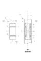
図1に示すように本発明の1例であるマイクロバブル生成器1は、気体を溶解した液体5からマイクロバブルを生成するマイクロバブル生成器であって、筒2と、Oリング3、3と、からなる。
As shown in FIG. 1, a microbubble generator 1 as an example of the present invention is a microbubble generator that generates microbubbles from a liquid 5 in which a gas is dissolved, and includes a
筒2は、外周に全周にわたって溝2a、2aが穿設され、内部に液体5を通し、マイクロバブルを生成するマイクロバブル生成路を備える。筒2は送液管4に挿入されるため、両端部はテーパー2bとすると、送液管4への筒2の挿入がスムーズになる。
The
マイクロバブル生成路は、液体5の入口側端部から液体5の流れ方向の中心部にいくにしたがって内径が徐々に狭まる第一流路2cと、第一流路2cに接続する第二流路2dと、第二流路2dに接続し液体5の出口側他端に向け内径が徐々に広がる第三流路2eと、からなる。なお、図1では、液体5の流れは上から下として示しているが、図1のマイクロバブル生成路を備えるマイクロバブル生成器1では、液体5の流れは上下逆転しても構わない。このような形状であれば、設置の向きを気にする必要がなく、設置方向を誤ることもない。
The microbubble generation path includes a
Oリング3は、溝2aに嵌められ弾性を備え、筒2側面の外径より外径が大きい輪である。例えば、輪状のゴム製パッキン、シリコン製雄パッキンなどが例示できる。素材は、流れる液体5により適宜選択する。
The O-
このようにしてなるマイクロバブル生成器1は、液体5を被送液場所に流す送液管4内に配置され、Oリング3が送液管4と筒2との間に位置し、送液管4と筒2とで挟まれ、圧縮され、送液管4と筒2との間をシールする。この結果、簡易に、マイクロバブル生成器1を送液管4の内部に配置できるとともに、液体5をもれなくマイクロバブル生成路に流すことができ、液体5の圧力損失なく利用することができることとなる。マイクロバブル生成器1は、送液管4内で液体5の流れに押され、送液管4の端部、段差部、細くなった送液管部、或いは湾曲部に係止されてもよいし、送液管4をつぶすことなどで任意の場所に係止することもできる。
The microbubble generator 1 thus configured is disposed in a
図1に示すように本発明の1例であるマイクロバブル生成管路構造1aは、被送液場所にマイクロバブル混合液体を供給する管路構造であって、被送液場所に液体5を流す送液管4と、送液管4内に配置され、Oリング3で送液管4と筒2との間をシールするマイクロバブル生成器1と、からなる。
As shown in FIG. 1, a microbubble generation pipeline structure 1 a which is an example of the present invention is a pipeline structure for supplying a microbubble mixed liquid to a liquid feeding location, and the liquid 5 is allowed to flow to the liquid feeding location. It consists of a
このような、マイクロバブル生成管路構造1aは、一般的な水道水を利用して、その管路でキャビテーションを起こさせ、水道水に含有されている空気を簡易かつ低廉にマイクロバブル化することができる。実施例2、3も同様である。 Such a microbubble generating pipeline structure 1a uses general tap water, causes cavitation in the pipeline, and microbubbles the air contained in tap water easily and inexpensively. Can do. The same applies to Examples 2 and 3.
例えば、送液場所が、洗濯器、食器洗浄器、水洗便器などであれば、それら洗浄場所に水道水などを流す給水管内にマイクロバブル生成器を配置することで、簡易にマイクロバブル生成管路構造を構築することができる。さらに、給水管として、自動車、航空機などの洗浄装置の水を通す配管、例えばスプレー管、なども例示することができる。 For example, if the liquid feeding place is a washing machine, a dishwasher, a flush toilet, etc., a microbubble generator can be easily provided by arranging a microbubble generator in a water supply pipe for flowing tap water to the washing place. A structure can be built. Furthermore, examples of the water supply pipe include a pipe through which water of a cleaning device such as an automobile and an aircraft passes, such as a spray pipe.
そして、マイクロバブル混合水がそれら被送液場所に送液されることで、それら被送液場所での洗浄力が向上するとともに、その後に続く排水路内の洗浄効果も期待できる。 And since microbubble mixed water is sent to these liquid feeding places, while the detergency in those liquid feeding places improves, the washing | cleaning effect in the subsequent drainage channel can also be anticipated.
また、送液場所が、内燃機関(エンジン)であれば、内燃機関の燃料噴射孔に連結する管路にマイクロバブルを発生させるためのマイクロバブル生成器(例えば、後述のマイクロバブル生成器26)を設けて、燃料をマイクロバブル状にして噴射させることにより燃焼効率の向上が期待できる。同様に、バーナーなどの燃焼機器の燃料噴射孔に連結する管路にマイクロバブルを発生させるためのマイクロバブル生成器を設けて燃費効率を上げることができる。
Further, if the liquid feeding place is an internal combustion engine (engine), a microbubble generator for generating microbubbles in a pipe line connected to a fuel injection hole of the internal combustion engine (for example, a
内燃機関を備えたものとして、オートモービルが例示できる。オートモービルには、自動車、自動二輪車が含まれる。また、火力発電所などにも応用できる。 Automobiles can be exemplified as those having an internal combustion engine. Automobiles include automobiles and motorcycles. It can also be applied to thermal power plants.
その他、船舶の船首部分の船底にマイクロバブルを発生させるためのマイクロバブル生成管路構造を設けて、マイクロバブルを生成し、船底に流し、船底の抵抗を削減させ、船舶のスピードアップを図ることができる。 In addition, a microbubble generation pipe line structure for generating microbubbles at the bottom of the ship's bow is provided to generate microbubbles and flow them to the bottom of the ship, reducing the resistance of the bottom and speeding up the ship. Can do.
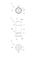
図2−4に示すように本発明の1例であるマイクロバブル生成器11は、気体を溶解した液体5からマイクロバブルを生成するマイクロバブル生成器であって、筒12と、Oリング3、3と、からなる。
As shown in FIG. 2-4, the
筒12は、外周に全周にわたって溝2a、2aが穿設され、一方の端部にフランジ12fを設け、内部に液体5を通しマイクロバブルを生成するマイクロバブル生成路(第一流路2c、第二流路2d、第三流路2e)を備える。
The
このようにしてなるマイクロバブル生成器11は、液体5を被送液場所に流す送液管4の端部にフランジ12fで係止されるとともに、実施例1同様に、送液管4と筒12との間をOリング3でシールする。液体5の流れは上下逆転しても構わない。図3(B)、(C)に示すように、送液管4の端部に係止される。
The
図4に、マイクロバブル生成器11を利用した、水洗便器(小便器13)用のマイクロバブル生成管路構造11aを示した。マイクロバブル生成器11を導入した箇所は、陶磁器製の小便器13に水洗トイレ用流水5a(水道水)を供給する、既存のスパッドの給水管4aの端部である。
In FIG. 4, the microbubble production | generation
マイクロバブル生成管路構造11aは、小便器13内にマイクロバブル混合液体を供給する管路構造であって、水洗トイレ用流水5aを小便器13に送る給水管4aと、給水管4aの端部にフランジ12fで係止されるとともに前記給水管と筒との間を前記Oリングでシールするマイクロバブル生成器11と、からなる。
The microbubble generation
次に、マイクロバブル生成管路構造11aの組み立てについて、説明する。陶磁器製の小便器13は、図4に示すように、給水管4aから供給される水洗トイレ用流水5aを、底部に孔13rが穿設された空洞部13pで受け、孔13rから洗浄水5bとして、小便器13の壁に分散して流す。スパッドを組み立てるには、小便器13の上面13aの開口部13n内で作業する。
Next, the assembly of the microbubble
先ず、小便器13の上面13aの開口部13nに、上部が管状で、内部に中心に向かって略水平の突出した突起13m、側面にネジ部13kを備え、下部がスカート状に拡張したノズル13bを空洞部13pに落とさないように挿入する。ノズル13bの拡張部は、開口部13nより径が小さい。
First, in the
続いて、ノズル13bを保持したまま、ゴム製のスカート状の三角パッキン13cをノズル13b上部からノズル13bに嵌めるとともに、開口部13n内に挿入する。その上で、ノズル13bの上部からパッキン13d、ワッシャ13hを挿入し、フランジ付きナット13eで、締め付ける。
Subsequently, while holding the
その結果ノズル13bは、小便器13の上面13aの開口部13nに固定されるとともに、三角パッキン13cでノズル13bと、開口部13nとの間をシールする。さらに、パッキン13dも開口部をシールする。
As a result, the
続いて、給水管4aの端部にマイクロバブル生成器11を圧入し、給水管4aをノズル13bの中へ挿入する。マイクロバブル生成器11はノズル13bの内フランジ13mに係止されることになる。また、給水管4aの端部の外周には、締め付けナット13g、ワッシャ13i、パッキン13fの順で、挿入しておく。
Subsequently, the
最後に、ノズル13bへ挿入された給水管4aを、締め付けナット13gで締め付けるとパッキン13fで、ノズル13bの上部がシールされる。また、Oリング3は、給水管4aと筒12との間をシールする。そして、マイクロバブル生成器11のフランジ12fは、給水管4aの端部とノズル13bの内フランジ13mとの間に位置する。
Finally, when the
このように、マイクロバブル生成器11を、スパッド構造を備える既設の小便器13に外観上の変更なしに導入できる。当然新設の場合も同じである。また、最近では、小便器の洗浄のための散水方式としては、スパッドを介して小便器の陶器部分に開口した孔13rから散水せずに、給水管から直接スプレッダーと呼ばれる樹脂製や金属製の拡散ノズルに直結し、散水するものもある。そのような構造の場合には、マイクロバブル生成器1の形状が適することもある。同様に、ロータンク式大便器への給水管にも導入することができ、マイクロバブル混合洗浄水を小便器や大便器へ導入することで、便器面のみならず、建物内に配管された排水管の管内の洗浄もできる。
In this manner, the
図5に示すように本発明の1例であるマイクロバブル生成器21は、気体を溶解した液体5からマイクロバブルを生成するマイクロバブル生成器であって、両端にネジを切ったジョイント管24と、キャビテーションを起こさせるための筒22と、パッキン23、23aと、からなる。
As shown in FIG. 5, a
ジョイント管24は、液体5を被送液場所に流す送液管4の端部4b、4c(点線)間に螺合し、内部にキャビテーションを起こさせるための筒22をジョイント管24に螺合させるための第二内ネジ部24cを備える。ジョイント管24の一端の内面には内ネジ部24aを、他端の外周には外ネジ部24bを備え、送液管4の両端部4b、4cのネジ部と螺合する。パッキン23aは、Oリングが例示できるが、Oリングに代えて送液管4の端部4bの先端部とジョイント管24の内部との間に、平パッキンを用いることもできる。
The
筒22は、一方の端部の外周に第二内ネジ部24cに螺合するネジ部22aを備え、ネジ部22a側の端部にフランジ22bを設けて当たり止めとし、内部には液体5を通しマイクロバブルを生成するマイクロバブル生成路(第一流路2c、第二流路2d、第三流路2e)を備える。そして、ジョイント管24と筒22との間を第二内ネジ部24cとネジ部22aとの螺合でシールする。
The
ジョイント管24の外ネジ部24bには輪状のパッキン23が嵌められ、ジョイント管24と送液管4の端部4cとをシールする。同様に、送液管4の端部4bにも輪状のパッキン23aが嵌められ、ジョイント管24と送液管4の端部4bとをシールする。ここでのシールは輪状のパッキンを図示したが、状況によっては平板状のパッキンやシールテープでシールしても良い。
A ring-shaped
このようなマイクロバブル生成器21であれば、送液管4の両端部4b、4cに連結するだけで、簡易にマイクロバブル生成管路構造21aを形成することができる。従って、既存の送液管4にも簡易にマイクロバブル生成器21を導入し、マイクロバブル混合液体を被送液場所に供給することができる。
If it is such a
被送液の入り口側のスペース25は被送液に回転を加えて旋回流とし、流速を上げるため、15度偏芯した4つの開口を持った樹脂製のプレートを取り付けるためのスペースである。このプレートは給水圧などの条件によっては取り付けた方が良い場合と取り付けないでもよい場合がある。
The
図6に示すように本発明の1例であるマイクロバブル生成器26は、気体を溶解した液体5からマイクロバブルを生成するマイクロバブル生成器であって、筒27の一端の外周にネジ部27a、内部にマイクロバブル生成流路を備える。マイクロバブル生成路は、前記第一流路2c、第二流路2d、第三流路2eである。
As shown in FIG. 6, a
ネジ部27aと送液管4の内部に設けた内ネジ部4eと螺合する。そして、止水は、既存のシールテープを用い、ネジ部27aに巻き、送液管4の内ネジ部4eに螺合させればよい。このようにして、既存の配管にマイクロバブル生成器を配置し、簡易にマイクロバブル生成管路構造26aを構築することができる。
The screw portion 27a and the inner screw portion 4e provided inside the
1 マイクロバブル生成器
1a マイクロバブル生成管路構造
2 筒
2a 溝
2b テーパー
2c 第一流路
2d 第二流路
2e 第三流路
3 Oリング
4 送液管
4a 給水管
4b 端部
4c 端部
4e ネジ部
5 液体
5a 水洗トイレ用流水
5b 洗浄水
11 マイクロバブル生成器
11a マイクロバブル生成管路構造
12 筒
12f フランジ
13 小便器
13a 上面
13b ノズル
13c 三角パッキン
13d パッキン
13e フランジ付きナット
13f パッキン
13g 締め付けナット
13h ワッシャ
13i ワッシャ
13k ネジ部
13m 内フランジ
13n 開口部
13p 空洞部
13r 孔
21 マイクロバブル生成器
21a マイクロバブル生成管路構造
22 筒
22a ネジ部
22b フランジ
23 パッキン
23a パッキン
24 ジョイント管
24a 内ネジ部
24b 外ネジ部
24c 第二内ネジ部
25 スペース
26 マイクロバブル生成器
26a マイクロバブル生成管路構造
27 筒
27a ネジ部
DESCRIPTION OF SYMBOLS 1 Micro bubble generator 1a Micro bubble production | generation
4
11
Claims (13)
外周に溝が穿設され内部に前記液体を通しマイクロバブルを生成するマイクロバブル生成路を備える筒と、前記溝に嵌められ弾性を備えるOリングと、からなり、
前記液体を被送液場所に流す送液管内に配置され、前記Oリングで前記送液管と前記筒との間をシールすることを特徴とするマイクロバブル生成器。 A microbubble generator that generates microbubbles from a gas-dissolved liquid,
A cylinder having a microbubble generating path for generating a microbubble through the liquid and having a groove formed in the outer periphery, and an O-ring fitted in the groove and having elasticity,
A microbubble generator characterized in that the microbubble generator is disposed in a liquid feeding pipe for flowing the liquid to a liquid feeding place, and seals between the liquid feeding pipe and the cylinder by the O-ring.
被送液場所に液体を流す送液管と、前記送液管内に配置され、前記Oリングで前記送液管と前記筒との間をシールする請求項1に記載のマイクロバブル生成器と、からなることを特徴とするマイクロバブル生成管路構造。 A pipe structure for supplying a microbubble mixed liquid to a liquid receiving place,
A microbubble generator according to claim 1, wherein the microbubble generator according to claim 1 is arranged in the liquid feeding pipe, and the O-ring seals between the liquid feeding pipe and the cylinder. A microbubble generating conduit structure characterized by comprising:
外周に溝が穿設され一方の端部にフランジを設け内部に前記液体を通しマイクロバブルを生成するマイクロバブル生成路を備える筒と、前記溝に嵌められ弾性を備えるOリングと、からなり、
前記液体を被送液場所に流す送液管の端部に前記フランジで係止されるとともに、前記送液管と前記筒との間を前記Oリングでシールすることを特徴とするマイクロバブル生成器。 A microbubble generator that generates microbubbles from a gas-dissolved liquid,
A cylinder having a microbubble generation path for generating a microbubble through the liquid inside by providing a flange at one end and providing a flange at one end, and an O-ring fitted in the groove and having elasticity,
Microbubble generation characterized in that it is locked by the flange to the end of a liquid feed pipe that causes the liquid to flow to a liquid feed location, and the O-ring is sealed between the liquid feed pipe and the cylinder vessel.
前記液体が水道水、前記被送液場所が水洗便器、前記送液管が給水管であり、前記水洗便器に前記水道水を流す前記給水管と、前記給水管の端部に前記フランジで係止されるとともに前記給水管と前記筒との間を前記Oリングでシールする請求項3に記載のマイクロバブル生成器と、からなることを特徴とするマイクロバブル生成管路構造。 A pipe structure for supplying a microbubble mixed liquid to a liquid receiving place,
The liquid is tap water, the liquid delivery place is a flush toilet, the liquid feed pipe is a water supply pipe, the water supply pipe for flowing the tap water to the flush toilet, and the flange at the end of the water supply pipe A microbubble generating pipe line structure comprising: the microbubble generator according to claim 3 which is stopped and sealed between the water supply pipe and the cylinder by the O-ring.
前記液体を被送液場所に流す送液管の端部間に螺合し内部に第二内ネジ部を備えるジョイント管と、一方の端部の外周に前記第二内ネジ部に螺合するネジ部を備え前記ネジ部側の端部にフランジを設け内部に前記液体を通しマイクロバブルを生成するマイクロバブル生成路を備える筒と、からなり、前記ジョイント管と前記筒との間を前記第二内ネジ部とネジ部との螺合でシールすることを特徴とするマイクロバブル生成器。 A microbubble generator that generates microbubbles from a gas-dissolved liquid,
A joint pipe that is screwed between ends of a liquid feeding pipe that flows the liquid to a liquid feeding place and has a second internal thread inside, and is screwed to the second internal thread on the outer periphery of one end. And a cylinder provided with a microbubble generating path for generating a microbubble through the liquid by providing a flange at an end on the screw part side and including the threaded portion, and the first pipe between the joint pipe and the cylinder. A microbubble generator characterized in that sealing is performed by screwing between two inner thread portions and a thread portion.
被送液場所に液体を流す送液管と、前記送液管の端部間に前記ジョイント管が螺合するとともに前記ジョイント管と前記筒との間を前記第二内ネジ部とネジ部の螺合でシールする請求項5に記載のマイクロバブル生成器と、からなることを特徴とするマイクロバブル生成管路構造。 A pipe structure for supplying a microbubble mixed liquid to a liquid receiving place,
A liquid feed pipe for flowing liquid to a liquid feed place, and the joint pipe is screwed between end portions of the liquid feed pipe, and between the joint pipe and the cylinder, the second internal thread portion and the screw portion 6. A microbubble generator pipe structure according to claim 5, wherein the microbubble generator is sealed by screwing.
Priority Applications (1)
| Application Number | Priority Date | Filing Date | Title |
|---|---|---|---|
| JP2013018615A JP2014147901A (en) | 2013-02-01 | 2013-02-01 | Microbubble generator and microbubble generating tube structure |
Applications Claiming Priority (1)
| Application Number | Priority Date | Filing Date | Title |
|---|---|---|---|
| JP2013018615A JP2014147901A (en) | 2013-02-01 | 2013-02-01 | Microbubble generator and microbubble generating tube structure |
Related Child Applications (1)
| Application Number | Title | Priority Date | Filing Date |
|---|---|---|---|
| JP2017034216A Division JP6369879B2 (en) | 2017-02-25 | 2017-02-25 | Microbubble generator and microbubble generation pipeline structure |
Publications (1)
| Publication Number | Publication Date |
|---|---|
| JP2014147901A true JP2014147901A (en) | 2014-08-21 |
Family
ID=51571363
Family Applications (1)
| Application Number | Title | Priority Date | Filing Date |
|---|---|---|---|
| JP2013018615A Pending JP2014147901A (en) | 2013-02-01 | 2013-02-01 | Microbubble generator and microbubble generating tube structure |
Country Status (1)
| Country | Link |
|---|---|
| JP (1) | JP2014147901A (en) |
Cited By (18)
| Publication number | Priority date | Publication date | Assignee | Title |
|---|---|---|---|---|
| JP2016049509A (en) * | 2014-09-01 | 2016-04-11 | 株式会社大気社 | Surface treatment device utilizing micro-bubbles |
| WO2016195116A3 (en) * | 2015-06-02 | 2017-01-19 | 株式会社ウォーターデザイン | Liquid processing nozzle, liquid processing method using same, gas dissolution method, and gas dissolution device |
| WO2017018143A1 (en) * | 2015-07-29 | 2017-02-02 | 東芝ライフスタイル株式会社 | Solenoid valve for liquid, method for producing solenoid valve for liquid, and washing machine |
| CN107022871A (en) * | 2016-01-29 | 2017-08-08 | 吴承焕 | Use the washing methods and device of effective dissolving concentration technique of nano bubble |
| JP2017185444A (en) * | 2016-04-05 | 2017-10-12 | 株式会社micro−bub | Microbubble generator for faucet with head-shaking pipe and faucet with head-shaking pipe |
| JP2018008193A (en) * | 2016-07-12 | 2018-01-18 | 株式会社micro−bub | Microbubble generator for faucet and faucet incorporating microbubble generator |
| JP2018012919A (en) * | 2016-07-19 | 2018-01-25 | 東日本旅客鉄道株式会社 | Urinal with washing mechanism and liquid processing nozzle used for the same |
| WO2018026216A1 (en) * | 2016-08-04 | 2018-02-08 | 엘지전자 주식회사 | Dish washer |
| WO2018124717A1 (en) * | 2016-12-27 | 2018-07-05 | 엘지전자 주식회사 | Dishwasher |
| KR20180115636A (en) * | 2017-04-13 | 2018-10-23 | 도시바 라이프스타일 가부시키가이샤 | Dishwasher |
| CN108729513A (en) * | 2017-04-13 | 2018-11-02 | 东芝生活电器株式会社 | Water-closet for bowl device, ejected wash water cistern device and partial cleaning arrangement |
| KR20180138361A (en) * | 2017-06-21 | 2018-12-31 | 황재구 | Hydroponic system having micro bubble generator |
| JP2019025451A (en) * | 2017-08-02 | 2019-02-21 | 株式会社富士計器 | Fine bubble water generator |
| JP2019122904A (en) * | 2018-01-15 | 2019-07-25 | 株式会社三進製作所 | Microbubble generating tool and microbubble generator |
| JP2021067169A (en) * | 2019-03-04 | 2021-04-30 | 株式会社富士計器 | Urolith removal system |
| WO2022054271A1 (en) * | 2020-09-14 | 2022-03-17 | 水素パワー株式会社 | Fuel reforming device |
| JP7042540B1 (en) * | 2021-11-16 | 2022-03-28 | 株式会社アプライド・エナジー・ラボラトリー | Combustion efficiency improvement device |
| JP7292633B2 (en) | 2020-06-02 | 2023-06-19 | 株式会社丸山製作所 | Chemical spraying device |
Citations (11)
| Publication number | Priority date | Publication date | Assignee | Title |
|---|---|---|---|---|
| JPS6019958A (en) * | 1983-07-12 | 1985-02-01 | Agency Of Ind Science & Technol | Fuel feeder |
| JPH11319637A (en) * | 1998-05-08 | 1999-11-24 | Three Hill:Kk | Fine bubble generating nozzle |
| JP2005028305A (en) * | 2003-07-07 | 2005-02-03 | Institute Of Computational Fluid Dynamics | Gas-liquid mixture production device, sewage purifying device and fuel injection equipment |
| JP2008229516A (en) * | 2007-03-20 | 2008-10-02 | Univ Of Tsukuba | Microbubble shower |
| JP2009136864A (en) * | 2007-11-16 | 2009-06-25 | Nippon Sozai Kk | Microbubble generator |
| JP2010029649A (en) * | 2008-06-04 | 2010-02-12 | Yasutaka Sakamoto | Shower apparatus with microbubble generation function |
| JP2010246672A (en) * | 2009-04-14 | 2010-11-04 | Tanaka Kinzoku Seisakusho:Kk | Showerhead |
| JP2011083772A (en) * | 2010-12-03 | 2011-04-28 | Panasonic Electric Works Co Ltd | Apparatus for producing microbubble |
| JP2012096216A (en) * | 2010-11-04 | 2012-05-24 | Yasutaka Sakamoto | Bubble micronizing nozzle, microbubble generator using the same, method for producing microbubble-containing water, article washing apparatus, article washing method, method for culturing marine product, hydroponic culture method, and shower apparatus |
| WO2013012069A1 (en) * | 2011-07-21 | 2013-01-24 | 株式会社シバタ | Bubble generating mechanism and showerhead with bubble generating mechanism |
| WO2013011570A1 (en) * | 2011-07-20 | 2013-01-24 | 株式会社Japan Star | Bubble generation mechanism and shower head with bubble generation mechanism |
-
2013
- 2013-02-01 JP JP2013018615A patent/JP2014147901A/en active Pending
Patent Citations (11)
| Publication number | Priority date | Publication date | Assignee | Title |
|---|---|---|---|---|
| JPS6019958A (en) * | 1983-07-12 | 1985-02-01 | Agency Of Ind Science & Technol | Fuel feeder |
| JPH11319637A (en) * | 1998-05-08 | 1999-11-24 | Three Hill:Kk | Fine bubble generating nozzle |
| JP2005028305A (en) * | 2003-07-07 | 2005-02-03 | Institute Of Computational Fluid Dynamics | Gas-liquid mixture production device, sewage purifying device and fuel injection equipment |
| JP2008229516A (en) * | 2007-03-20 | 2008-10-02 | Univ Of Tsukuba | Microbubble shower |
| JP2009136864A (en) * | 2007-11-16 | 2009-06-25 | Nippon Sozai Kk | Microbubble generator |
| JP2010029649A (en) * | 2008-06-04 | 2010-02-12 | Yasutaka Sakamoto | Shower apparatus with microbubble generation function |
| JP2010246672A (en) * | 2009-04-14 | 2010-11-04 | Tanaka Kinzoku Seisakusho:Kk | Showerhead |
| JP2012096216A (en) * | 2010-11-04 | 2012-05-24 | Yasutaka Sakamoto | Bubble micronizing nozzle, microbubble generator using the same, method for producing microbubble-containing water, article washing apparatus, article washing method, method for culturing marine product, hydroponic culture method, and shower apparatus |
| JP2011083772A (en) * | 2010-12-03 | 2011-04-28 | Panasonic Electric Works Co Ltd | Apparatus for producing microbubble |
| WO2013011570A1 (en) * | 2011-07-20 | 2013-01-24 | 株式会社Japan Star | Bubble generation mechanism and shower head with bubble generation mechanism |
| WO2013012069A1 (en) * | 2011-07-21 | 2013-01-24 | 株式会社シバタ | Bubble generating mechanism and showerhead with bubble generating mechanism |
Cited By (32)
| Publication number | Priority date | Publication date | Assignee | Title |
|---|---|---|---|---|
| JP2016049509A (en) * | 2014-09-01 | 2016-04-11 | 株式会社大気社 | Surface treatment device utilizing micro-bubbles |
| WO2016195116A3 (en) * | 2015-06-02 | 2017-01-19 | 株式会社ウォーターデザイン | Liquid processing nozzle, liquid processing method using same, gas dissolution method, and gas dissolution device |
| US10844973B2 (en) | 2015-07-29 | 2020-11-24 | Toshiba Lifestyle Products & Services Corporation | Liquid electromagnetic valve, method of manufacturing liquid electromagnetic valve, and washing machine |
| WO2017018143A1 (en) * | 2015-07-29 | 2017-02-02 | 東芝ライフスタイル株式会社 | Solenoid valve for liquid, method for producing solenoid valve for liquid, and washing machine |
| JP2017032001A (en) * | 2015-07-29 | 2017-02-09 | 東芝ライフスタイル株式会社 | Fluid solenoid valve, fluid solenoid valve manufacturing method, and washing machine |
| CN107022871A (en) * | 2016-01-29 | 2017-08-08 | 吴承焕 | Use the washing methods and device of effective dissolving concentration technique of nano bubble |
| CN107022871B (en) * | 2016-01-29 | 2020-01-03 | 吴承焕 | Washing method and apparatus using efficient dissolution concentration technique of nanobubbles |
| JP2017185444A (en) * | 2016-04-05 | 2017-10-12 | 株式会社micro−bub | Microbubble generator for faucet with head-shaking pipe and faucet with head-shaking pipe |
| JP2018008193A (en) * | 2016-07-12 | 2018-01-18 | 株式会社micro−bub | Microbubble generator for faucet and faucet incorporating microbubble generator |
| JP2018012919A (en) * | 2016-07-19 | 2018-01-25 | 東日本旅客鉄道株式会社 | Urinal with washing mechanism and liquid processing nozzle used for the same |
| US10912441B2 (en) | 2016-08-04 | 2021-02-09 | Lg Electronics Inc. | Dishwasher |
| WO2018026216A1 (en) * | 2016-08-04 | 2018-02-08 | 엘지전자 주식회사 | Dish washer |
| WO2018124717A1 (en) * | 2016-12-27 | 2018-07-05 | 엘지전자 주식회사 | Dishwasher |
| US11076741B2 (en) | 2016-12-27 | 2021-08-03 | Lg Electronics Inc. | Dishwasher |
| US11864709B2 (en) | 2016-12-27 | 2024-01-09 | Lg Electronics Inc. | Dishwasher |
| KR20180115636A (en) * | 2017-04-13 | 2018-10-23 | 도시바 라이프스타일 가부시키가이샤 | Dishwasher |
| KR102060334B1 (en) * | 2017-04-13 | 2019-12-30 | 도시바 라이프스타일 가부시키가이샤 | A flush toilet device, a flushing water tank, and a local cleaning device |
| KR102102194B1 (en) * | 2017-04-13 | 2020-04-20 | 도시바 라이프스타일 가부시키가이샤 | Dishwasher |
| JP2018178538A (en) * | 2017-04-13 | 2018-11-15 | 東芝ライフスタイル株式会社 | Flush toilet stool device, washing water tank device and local cleaner |
| CN108729513A (en) * | 2017-04-13 | 2018-11-02 | 东芝生活电器株式会社 | Water-closet for bowl device, ejected wash water cistern device and partial cleaning arrangement |
| KR101985779B1 (en) * | 2017-06-21 | 2019-06-04 | 황재구 | Hydroponic system having micro bubble generator |
| KR20180138361A (en) * | 2017-06-21 | 2018-12-31 | 황재구 | Hydroponic system having micro bubble generator |
| JP7012482B2 (en) | 2017-08-02 | 2022-01-28 | 株式会社富士計器 | Fine bubble water generator |
| JP2019025451A (en) * | 2017-08-02 | 2019-02-21 | 株式会社富士計器 | Fine bubble water generator |
| JP2019122904A (en) * | 2018-01-15 | 2019-07-25 | 株式会社三進製作所 | Microbubble generating tool and microbubble generator |
| JP7018610B2 (en) | 2018-01-15 | 2022-02-14 | 株式会社三進製作所 | Micro bubble generator and micro bubble generator |
| JP2021067169A (en) * | 2019-03-04 | 2021-04-30 | 株式会社富士計器 | Urolith removal system |
| JP7292633B2 (en) | 2020-06-02 | 2023-06-19 | 株式会社丸山製作所 | Chemical spraying device |
| WO2022054271A1 (en) * | 2020-09-14 | 2022-03-17 | 水素パワー株式会社 | Fuel reforming device |
| JP7465985B2 (en) | 2020-09-14 | 2024-04-11 | 水素パワー株式会社 | Fuel Reformer |
| JP7042540B1 (en) * | 2021-11-16 | 2022-03-28 | 株式会社アプライド・エナジー・ラボラトリー | Combustion efficiency improvement device |
| WO2023090027A1 (en) * | 2021-11-16 | 2023-05-25 | 株式会社アプライド・エナジー・ラボラトリー | Combustion efficiency improvement device |
Similar Documents
| Publication | Publication Date | Title |
|---|---|---|
| JP2014147901A (en) | Microbubble generator and microbubble generating tube structure | |
| JP4002439B2 (en) | Microbubble generating nozzle and its application device | |
| JP7012482B2 (en) | Fine bubble water generator | |
| KR100950345B1 (en) | Shower using air pressure with extended tube | |
| US10124363B2 (en) | Shower head capable of providing shower feeling without water spray plate | |
| JP2012130901A (en) | Bubble generator | |
| JP6579547B2 (en) | Micro bubble generator for faucet and faucet with built-in micro bubble generator | |
| JP6369879B2 (en) | Microbubble generator and microbubble generation pipeline structure | |
| WO2019049650A1 (en) | Microbubble liquid generator | |
| CN207324530U (en) | Microbubble generator | |
| CN202252104U (en) | Jet flow water mixer | |
| JP2021510116A (en) | Cavitation member of micro bubble generator, micro bubble generator and washing equipment | |
| US20050051577A1 (en) | Fluid mixing device and dispensing system | |
| JP6570474B2 (en) | Micro bubble generator for faucet with swing pipe and faucet with swing pipe | |
| CN105156720A (en) | Water mixing pressure ejector and pressurizing tap | |
| JP3213014U (en) | Microbubble water generator for washing machines | |
| CN214183630U (en) | Self-propelled straight-rotating mixed jet nozzle for cleaning pipeline | |
| CN202277915U (en) | Self-excitation pulse aeration shower nozzle | |
| CN207952159U (en) | Water-air mix cleaning device | |
| CN210522848U (en) | Water-saving spraying equipment | |
| CN203515531U (en) | Filling pipeline based on balance tank instillation device | |
| JP6994549B1 (en) | Shower hose with fine bubble water generator | |
| CN207054306U (en) | A kind of flowers are irrigated and use multiple water-pouring functions joint | |
| CN102434985B (en) | Water jet nozzle for solar water heating system | |
| TWI764263B (en) | Micro-bubble generator |
Legal Events
| Date | Code | Title | Description |
|---|---|---|---|
| A621 | Written request for application examination |
Free format text: JAPANESE INTERMEDIATE CODE: A621 Effective date: 20151210 |
|
| A977 | Report on retrieval |
Free format text: JAPANESE INTERMEDIATE CODE: A971007 Effective date: 20160923 |
|
| A131 | Notification of reasons for refusal |
Free format text: JAPANESE INTERMEDIATE CODE: A131 Effective date: 20161026 |
|
| A601 | Written request for extension of time |
Free format text: JAPANESE INTERMEDIATE CODE: A601 Effective date: 20161223 |
|
| A521 | Request for written amendment filed |
Free format text: JAPANESE INTERMEDIATE CODE: A523 Effective date: 20170225 |
|
| A02 | Decision of refusal |
Free format text: JAPANESE INTERMEDIATE CODE: A02 Effective date: 20170420 |