JP2014142045A - Regeneration method of existing pipe - Google Patents
Regeneration method of existing pipe Download PDFInfo
- Publication number
- JP2014142045A JP2014142045A JP2013012001A JP2013012001A JP2014142045A JP 2014142045 A JP2014142045 A JP 2014142045A JP 2013012001 A JP2013012001 A JP 2013012001A JP 2013012001 A JP2013012001 A JP 2013012001A JP 2014142045 A JP2014142045 A JP 2014142045A
- Authority
- JP
- Japan
- Prior art keywords
- pipe
- rehabilitation
- existing pipe
- existing
- tube
- Prior art date
- Legal status (The legal status is an assumption and is not a legal conclusion. Google has not performed a legal analysis and makes no representation as to the accuracy of the status listed.)
- Pending
Links
Images


Landscapes
- Lining Or Joining Of Plastics Or The Like (AREA)
- Pipe Accessories (AREA)
Abstract
Description
本発明は、既成管の更生技術に関する。 The present invention relates to an existing pipe rehabilitation technique.
下水道管などの既設管が老朽化し、ひび割れや腐食等が生じた場合に、既設管の内側に更生管を築造し、既設管の内面と更生管との間に、モルタル等の裏込め材を注入する管の更生工法が知られている。例えば、下記の特許文献1は、樹脂製のプロファイルを巻回して更生管を築造する技術を開示している。かかる更生工法は、既設管と更生管とを裏込め材を介して一体化させ、一体構造で外力に抵抗することで、既設管を補強するものである。かかる更生工法によれば、道路を掘り起こすことなく、老朽化した既成管の更生が可能である。 When existing pipes such as sewer pipes become obsolete and cracks, corrosion, etc. occur, rehabilitation pipes are built inside the existing pipes, and mortar and other backfill materials are placed between the inner surfaces of the existing pipes and the rehabilitation pipes. Rehabilitation methods for pipes to be injected are known. For example, the following Patent Document 1 discloses a technique for building a rehabilitation pipe by winding a resin profile. This rehabilitation method reinforces an existing pipe by integrating the existing pipe and the rehabilitation pipe through a backfilling material and resisting external force with an integral structure. According to this rehabilitation method, it is possible to rehabilitate an old existing pipe without digging up a road.
こうした更生工法では、一体構造をいっそう強化することが、既設管の補強効果を向上させる上で望ましい。 In such a rehabilitation method, it is desirable to further strengthen the integrated structure in order to improve the reinforcement effect of the existing pipe.
本発明は、上述の課題を解決するためになされたものであり、例えば、以下の形態として実現することが可能である。 The present invention has been made to solve the above-described problems, and can be realized, for example, as the following forms.
本発明の第1の形態は、コンクリート材料を含んで形成された既成管の更生方法として提供される。この更生方法は、既成管の内面に高圧水を噴射して、相対的に強度が高い部位のみが残るように内面をはつる第1の工程と、既成管の内側において、更生管を築造する第2の工程と、第1の工程においてはつられた既成管の内面と、第2の工程において築造された更生管との間に、裏込め材を注入する第3の工程とを備える。 The 1st form of this invention is provided as a rehabilitation method of the existing pipe formed including the concrete material. In this rehabilitation method, high pressure water is jetted onto the inner surface of the existing pipe, and the first step of holding the inner surface so that only a relatively high strength portion remains, and the rehabilitation pipe is built inside the existing pipe. A second step, and a third step of injecting a backfill material between the inner surface of the pre-formed pipe formed in the first step and the rehabilitated pipe built in the second step.
かかる更生工法によれば、裏込め材が、既成管の内面のうちのはつりによって残った部位に食い込むことによって、アンカー効果を発揮する。したがって、裏込め材と既成管とが好適に一体化される。しかも、はつりによって相対的に強度が高い部位が残り、当該部位がアンカー効果を発揮するので、裏込め材と既成管との密着性が向上し、裏込め材と既成管との一体関係は、強固なものとなる。その結果、既設管の補強効果が向上する。 According to this rehabilitation method, the backfill material exerts an anchor effect by biting into the portion of the inner surface of the existing pipe that remains due to the suspension. Therefore, the backfill material and the existing pipe are preferably integrated. In addition, a relatively high strength portion remains due to the hanger, and the portion exhibits an anchor effect, so that the adhesion between the backfill material and the prefabricated pipe is improved, and the integral relationship between the backfill material and the prefabricated pipe is: It will be solid. As a result, the reinforcing effect of the existing pipe is improved.
本発明の第2の形態として、第1の形態において、第2の工程は、既成管の内側において、樹脂製のプロファイルを巻回することによって、更生管を築造するものであってもよい。かかる形態によれば、更生管の成形が行いやすく、また、比較的安価に更生管を築造できる。 As a second form of the present invention, in the first form, the second step may be to build a rehabilitated pipe by winding a resin profile inside the pre-made pipe. According to such a form, the rehabilitation pipe can be easily formed, and the rehabilitation pipe can be constructed at a relatively low cost.
A.実施例:
図1は、本発明の一実施例としての既成管20の更生工法の手順を示す。図2は、図1に示す各工程における管の状態を模式的に示す。図2では、管の状態を容易に把握できるように細部を拡大して図示しているので、そのスケールは、実物とは一致していない。図1に示すように、既成管20の更生においては、まず、既成管20の内部の清掃を行う(ステップS110)。図2(a)に示すように、更生対象となる既成管20は、本実施例では、円形断面を有する下水管である。ただし、既成管20の形状は、特に限定するものではなく、既成管20は、例えば、矩形断面を有していてもよい。また、既成管20は、下水道管に限らず、任意の用途、例えば、農業用の管とすることができる。かかる既成管20は、コンクリート材料を含んで形成されている。
A. Example:
FIG. 1 shows a procedure of a rehabilitation method for an existing
既成管20の内部を清掃すると、次に、図1に示すように、高圧水を既成管20の内面21に噴射して、内面21を形成するコンクリートのはつり工を行う(ステップS120)。このはつり工は、本実施例では、内面21の全面に対して行われる。高圧水によるはつりは、カッタなどによる機械的なはつり工法と異なり、相対的に強度が低い部分が優先的にはつられる特性を有している。本実施例では、かかる特性を利用し、水圧や噴射時間を調節することによって、相対的に強度が高い部分を所望の程度残すように、はつり工が行われる。
When the inside of the
本実施例では、ステップS120は、既成管20の内部の略中央において、既成管20の流れ方向に沿ってガイドレールを配置し、当該ガイドレール上に設けられた高圧水噴射ノズル(以下、単にノズルとも呼ぶ)から内面21に向けて高圧水を噴射させながら、当該ノズルを流れ方向に移動させることによって施工される。この移動速度を調節することによって、単位面積あたりの噴射時間が調節される。ノズルを移動させる手段は、特に限定するものではなく、電動式であってもよいし、油圧式であってもよい。本実施例では、ノズルは、手動操作によってガイドレールの周囲を周方向に回転可能に構成されており、周方向の向き、すなわち、噴射方向を変えることができ、所定の領域のはつり工が完了するたびに、噴射方向が少しずつずらされ、その度に流れ方向への移動および噴射が繰り返される。これによって、内面21を周方向に満遍なくはつることができる。なお、噴射方向の変更は、自動化されてもよい。もとより、はつり工の態様は、特に限定するものではなく、作業員が可搬式のノズルを持って既成管20の内部に入り、はつりを手動作業で行ってもよい。
In the present embodiment, in step S120, a guide rail is arranged along the flow direction of the
図2(b)に示すように、かかるはつり工によって、既成管20の内面21がはつられることによって、はつり面22が形成される。はつり面22には、多数の凹凸形状23が形成される。かかる凹凸形状23は、半径方向の凹凸のみに限らず、半径方向と交差する方向にも形成される。なお、ステップS120は、上記のステップS110のうちの内面21の清掃を兼ねることができる。
As shown in FIG. 2 (b), the suspended
はつりを行うと、次に、図1に示すように、既成管20の内部に更生管30を築造する(ステップS130)。更生管30とは、既成管20の内部に設置される、既成管20の内径よりも外径が小さい管である。本実施例では、更生管30として、樹脂製のプロファイルを施工する。かかるプロファイルの施工方法は、公知であり、例えば、上述の特許文献1に記載されているので、簡単な説明に留めるが、例えば、以下のようにして施工できる。まず、自走式製管機を既成管20に配設して、この自走式製管機によって、帯状のプロファイルを螺旋状に巻回す。このプロファイルの一方の面には、後述するように、リブ31、メインロック用オス部およびメインロック用メス部が形成されている。自走式製管機は、既成管20内に配設された油圧ユニットにより作動制御される。油圧ユニットは、地上に配設された電動車により駆動制御される。自走式製管機は、嵌合ローラでプロファイルを挟み、嵌合ローラが回転しながら帯状のプロファイルを既成管20内に引き込むようになっている。そして、自走式製管機は、引き込んだプロファイルの一側部のメインロック用オス部を他側部のメインロック用メス部に連続的に嵌合しながら管状の更生管30を成形する。なお、更生管30の築造方法は、特に限定するものではなく、例えば、自走式に代えて、マンホール内に固定された製管機から、プロファイルを押し出す元押式であってもよい。
Once suspended, next, the
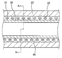
図2(c)および図3は、更生管30が築造された状態を示す。図3は、既成管20の長さ方向の断面を示す。図2(c)は、図3のA−A断面である。図2(c)に示すように、更生管30は、既成管20の内側で円形断面を有する形状に形成されている。既成管20が矩形断面を有している場合には、更生管30もそれに合わせた形状に形成される。既成管20のはつり面22と、更生管30との間には、空隙40が形成されている。図3に示すように、更生管30の外表面には、T字状に突出したリブ31が形成されている。なお、図3では、上述したメインロック用オス部およびメインロック用メス部は、図示を省略している。
FIG. 2C and FIG. 3 show a state where the
更生管30を築造すると、最後に、図1に示すように、裏込め材としてのモルタル50を空隙40に注入する(ステップS140)。モルタル50が硬化すると、図2(d)に示すように、既成管20の更生が完了する。なお、モルタル50の注入前に、更生管30の内部に支持工を設置してもよい。こうすれば、モルタル50の注入圧によって更生管30が変形したり、浮上したりすることを確実に防止できる。裏込め材には、モルタルに限らず、種々の樹脂材料を使用することも可能である。
When the
かかる更生によれば、モルタル50が、更生管30のリブ31に食い込むことによって、アンカー効果を発揮し、更生管30とモルタル50とが一体化される。しかも、モルタル50が、はつり面22の凹凸形状23に食い込むことによって、アンカー効果を発揮し、モルタル50と既成管20とが好適に一体化される。特に、モルタル50の凹凸形状23は、高圧水を噴射することによって、相対的に強度が高い部位のみで形成されるので、モルタル50と既成管20とは、強固に一体化される。換言すれば、凹凸形状23が形成されない従来の工法と比べて、モルタル50と既成管20との密着性は、大幅に向上する。その結果、老朽化した既成管20が、更生管30、モルタル50および既成管20が一体化された強度の高い複合管として更生される。なお、既成管20の内面21がはつられることによって、内面21に付着していた汚れが完全に除去されるとともに、接着機能を有する石灰成分が露出することになる。これらの事象も、モルタル50と既成管20との密着性の向上に寄与することとなる。
According to this rehabilitation, when the
特に、更生管30が、ボックスカルバートなどの略矩形断面を有する管である場合には、矩形形状の上側の面には、重力によって下方への力が作用することによって、更生管30とモルタル50との密着性(一体性)が比較的確保しにくいので、本実施例の工法は、有効である。
In particular, when the
凹凸形状23を形成することなく、モルタル50と既成管20とを接着剤で接着する工法も可能であるが、本実施例の工法によれば、接着剤のように温度や湿気などの制約を受けることがないので、施工を行いやすい。ただし、本実施例の工法は、接着剤の使用を排除するものではなく、本実施例の工法と接着剤の使用とを併用して、接着性をいっそう向上させることも可能である。
A method of bonding the
B.変形例:
B−1.変形例1:
上述の実施例では、既成管20の内面21を全面的にはつる例を示したが、はつり工の範囲は、内面21の一部分のみであってもよい。例えば、はつり工の範囲は、内面21の上部のみ(例えば、既成管20の上側半分のみ、既成管20の上側1/3のみ、など)であってもよい。こうしても、重力作用によって密着性を確保しにくい内面21の上部について、モルタル50との密着性を向上できる。
B. Variations:
B-1. Modification 1:
In the above-described embodiment, an example in which the
B−2.変形例2:
更生管30の築造工法および材質は、特に限定するものではなく、種々の態様とすることができる。例えば、樹脂製または金属製の管を推進または搬送組み立てによって、既成管20の内部に敷設してもよい。あるいは、フレキシブルな樹脂製の管材を既成管20の内部に引き込み、当該管材を空気圧、蒸気圧などで拡張させてもよい。
B-2. Modification 2:
The construction method and material of the
以上、いくつかの実施例に基づいて本発明の実施の形態について説明してきたが、上記した発明の実施の形態は、本発明の理解を容易にするためのものであり、本発明を限定するものではない。本発明は、その趣旨を逸脱することなく、変更、改良され得るとともに、本発明にはその等価物が含まれることはもちろんである。また、上述した課題の少なくとも一部を解決できる範囲、または、効果の少なくとも一部を奏する範囲において、特許請求の範囲および明細書に記載された各構成要素の組み合わせ、または、省略が可能である。 The embodiments of the present invention have been described above based on some examples. However, the above-described embodiments of the present invention are for facilitating the understanding of the present invention and limit the present invention. It is not a thing. The present invention can be changed and improved without departing from the gist thereof, and the present invention includes the equivalents thereof. Moreover, in the range which can solve at least one part of the subject mentioned above, or the range which exhibits at least one part of an effect, the combination of each component described in the claim and the specification, or omission is possible. .
20…既成管
21…内面
22…はつり面
23…凹凸形状
30…更生管
31…リブ
40…空隙
50…モルタル
20 ...
Claims (2)
前記既成管の内面に高圧水を噴射して、相対的に強度が高い部位のみが残るように前記内面をはつる第1の工程と、
前記既成管の内側において、更生管を築造する第2の工程と、
前記第1の工程においてはつられた前記既成管の内面と、前記第2の工程において築造された前記更生管との間に、裏込め材を注入する第3の工程と
を備えた既成管の更生方法。 A method for rehabilitating a prefabricated pipe formed with concrete material,
A first step of injecting high-pressure water onto the inner surface of the pre-formed pipe and suspending the inner surface so that only a relatively high strength portion remains;
A second step of constructing a rehabilitation pipe inside the pre-formed pipe;
And a third step of injecting a backfill material between the inner surface of the pre-formed tube formed in the first step and the rehabilitated tube constructed in the second step. Rehabilitation method.
前記第2の工程は、前記既成管の内側において、樹脂製のプロファイルを巻回することによって、前記更生管を築造する
既設管の更生方法。 A method for rehabilitating an existing pipe according to claim 1,
In the second step, the rehabilitated pipe is constructed by winding a resin profile inside the pre-formed pipe.
Priority Applications (1)
| Application Number | Priority Date | Filing Date | Title |
|---|---|---|---|
| JP2013012001A JP2014142045A (en) | 2013-01-25 | 2013-01-25 | Regeneration method of existing pipe |
Applications Claiming Priority (1)
| Application Number | Priority Date | Filing Date | Title |
|---|---|---|---|
| JP2013012001A JP2014142045A (en) | 2013-01-25 | 2013-01-25 | Regeneration method of existing pipe |
Publications (1)
| Publication Number | Publication Date |
|---|---|
| JP2014142045A true JP2014142045A (en) | 2014-08-07 |
Family
ID=51423494
Family Applications (1)
| Application Number | Title | Priority Date | Filing Date |
|---|---|---|---|
| JP2013012001A Pending JP2014142045A (en) | 2013-01-25 | 2013-01-25 | Regeneration method of existing pipe |
Country Status (1)
| Country | Link |
|---|---|
| JP (1) | JP2014142045A (en) |
Cited By (1)
| Publication number | Priority date | Publication date | Assignee | Title |
|---|---|---|---|---|
| JP2019031862A (en) * | 2017-08-09 | 2019-02-28 | 株式会社Ihi建材工業 | Method of repairing pipe body and existing pipe |
Citations (5)
| Publication number | Priority date | Publication date | Assignee | Title |
|---|---|---|---|---|
| JPH1054494A (en) * | 1996-08-09 | 1998-02-24 | Hazama Gumi Ltd | Pipeline lining method |
| JPH11200465A (en) * | 1998-01-14 | 1999-07-27 | Ohbayashi Corp | Method for forming anticorrosion lining layer inside aqueduct tunnel |
| JP2001207469A (en) * | 2000-01-27 | 2001-08-03 | Koyo Giken:Kk | Manhole repair method and manhole repair device |
| JP2006181861A (en) * | 2004-12-27 | 2006-07-13 | Sekisui Chem Co Ltd | Lining execution method of existing pipe and pipe making machine |
| JP2008266971A (en) * | 2007-04-19 | 2008-11-06 | Sekisui Chem Co Ltd | Pipe line rehabilitation method and rehabilitation pipe for use in it |
-
2013
- 2013-01-25 JP JP2013012001A patent/JP2014142045A/en active Pending
Patent Citations (5)
| Publication number | Priority date | Publication date | Assignee | Title |
|---|---|---|---|---|
| JPH1054494A (en) * | 1996-08-09 | 1998-02-24 | Hazama Gumi Ltd | Pipeline lining method |
| JPH11200465A (en) * | 1998-01-14 | 1999-07-27 | Ohbayashi Corp | Method for forming anticorrosion lining layer inside aqueduct tunnel |
| JP2001207469A (en) * | 2000-01-27 | 2001-08-03 | Koyo Giken:Kk | Manhole repair method and manhole repair device |
| JP2006181861A (en) * | 2004-12-27 | 2006-07-13 | Sekisui Chem Co Ltd | Lining execution method of existing pipe and pipe making machine |
| JP2008266971A (en) * | 2007-04-19 | 2008-11-06 | Sekisui Chem Co Ltd | Pipe line rehabilitation method and rehabilitation pipe for use in it |
Cited By (1)
| Publication number | Priority date | Publication date | Assignee | Title |
|---|---|---|---|---|
| JP2019031862A (en) * | 2017-08-09 | 2019-02-28 | 株式会社Ihi建材工業 | Method of repairing pipe body and existing pipe |
Similar Documents
| Publication | Publication Date | Title |
|---|---|---|
| KR101359448B1 (en) | Entire repairing method for pipe lines with non-excavation | |
| KR101415106B1 (en) | The back feel grouting apparatus for upper part of tunnel | |
| KR101043666B1 (en) | Reparing method of inner side of aged drains | |
| JP2003314197A (en) | Conduit repairing method and conduit interior repairing structure | |
| KR101732669B1 (en) | Reinforcement member, concrete box reinforced with the same and the construction method thereof | |
| JP2009133477A (en) | Method for regenerating existing pipe | |
| US20190049053A1 (en) | Corrugated metal pipe repair system and method | |
| KR101626395B1 (en) | Method for Repairing or Reinforcing Concrete Structure | |
| KR20100103038A (en) | Unequal tubular uniform plastering apparatus and internal plastering method using the same | |
| JP2004050719A (en) | Pipe lining method | |
| KR101029311B1 (en) | Non-excavation laying method for pipeline and tunnel using temporary composite pipe | |
| KR101394985B1 (en) | Tunnel reinforcement and tunnel grouting unit | |
| JP2014142045A (en) | Regeneration method of existing pipe | |
| WO2016013065A1 (en) | Method for rehabilitating existing pipe | |
| JP4793389B2 (en) | Construction method of joint part of underground wall, underground wall | |
| JP2004278203A (en) | Method of repairing liquid transportation facilities | |
| JP5600419B2 (en) | Existing pipe repair method | |
| JP2012219985A (en) | Regeneration structure and regeneration engineering method of existing pipe | |
| KR20060109377A (en) | Construction method of drain pipe | |
| RU149446U1 (en) | FLEXIBLE COMMUNICATION FOR THREE-LAYER FENDING STRUCTURES | |
| KR101743672B1 (en) | Single-sided split construction Medium to large diameter pipeline Unscraped interior repair method | |
| JP5430308B2 (en) | Existing pipe repair method | |
| JP4971233B2 (en) | Manhole repair method | |
| JP5918029B2 (en) | Rehabilitation method for existing pipes | |
| JP5774467B2 (en) | Pipe rehabilitation method |
Legal Events
| Date | Code | Title | Description |
|---|---|---|---|
| A131 | Notification of reasons for refusal |
Free format text: JAPANESE INTERMEDIATE CODE: A131 Effective date: 20140604 |
|
| A521 | Written amendment |
Free format text: JAPANESE INTERMEDIATE CODE: A523 Effective date: 20140703 |
|
| A521 | Written amendment |
Free format text: JAPANESE INTERMEDIATE CODE: A821 Effective date: 20140703 |
|
| A521 | Written amendment |
Free format text: JAPANESE INTERMEDIATE CODE: A523 Effective date: 20140804 |
|
| A02 | Decision of refusal |
Free format text: JAPANESE INTERMEDIATE CODE: A02 Effective date: 20150126 |
|
| A521 | Written amendment |
Free format text: JAPANESE INTERMEDIATE CODE: A523 Effective date: 20150427 |
|
| A911 | Transfer of reconsideration by examiner before appeal (zenchi) |
Free format text: JAPANESE INTERMEDIATE CODE: A911 Effective date: 20150522 |
|
| A912 | Removal of reconsideration by examiner before appeal (zenchi) |
Free format text: JAPANESE INTERMEDIATE CODE: A912 Effective date: 20150731 |