JP2014129664A - Method for installing caisson structure - Google Patents
Method for installing caisson structure Download PDFInfo
- Publication number
- JP2014129664A JP2014129664A JP2012287344A JP2012287344A JP2014129664A JP 2014129664 A JP2014129664 A JP 2014129664A JP 2012287344 A JP2012287344 A JP 2012287344A JP 2012287344 A JP2012287344 A JP 2012287344A JP 2014129664 A JP2014129664 A JP 2014129664A
- Authority
- JP
- Japan
- Prior art keywords
- box structure
- pipe
- gantry
- space
- box
- Prior art date
- Legal status (The legal status is an assumption and is not a legal conclusion. Google has not performed a legal analysis and makes no representation as to the accuracy of the status listed.)
- Granted
Links
Images


Landscapes
- Excavating Of Shafts Or Tunnels (AREA)
Abstract
Description
本発明は、函体構造物の設置方法に関し、特に、到達立坑側に函体構造物に対応した開口の空間が形成された路線下の当該空間以外の箇所に函体構造物を横断して構築する函体推進工法における函体構造物の設置方法に適用して有効な技術に関するものである。 The present invention relates to a method for installing a box structure, and in particular, traverses the box structure to a place other than the space under a route in which an opening space corresponding to the box structure is formed on the reach shaft side. The present invention relates to an effective technique applied to the installation method of the box structure in the box body propulsion method to be constructed.
走行する列車や車などの流れを阻害せずに、矩形断面を有する中空の函体構造物(例えば、プレキャストボックスカルバートなど)を路線下に横断して構築するためには函体推進工法(例えばR&C工法など)が用いられる。 In order to construct a hollow box structure (for example, precast box culvert etc.) having a rectangular cross section under the route without obstructing the flow of a traveling train or car, the box propulsion method (for example, R & C method etc.) are used.
この函体推進工法においては、函体構造物の構築予定位置と外面とが一致して並ぶようにして、断面中空矩形状となった複数本のパイプを、路線を横断する方向に沿って圧入しておく。そして、発進立坑側から推進ジャッキで函体構造物を推進させてパイプを到達立坑側に押し出しながら、函体構造物をパイプと置換して路線下に構築する。このとき、到達立坑側に押し出されたパイプは、到達立坑に組み立てておいた架台上に載せ、そこからクレーンで吊り上げて撤去される。 In this box body propulsion method, a plurality of pipes having a hollow rectangular cross section are press-fitted along the direction crossing the route so that the planned construction position of the box structure and the outer surface are aligned. Keep it. Then, while the box structure is pushed from the start shaft side with the propulsion jack and the pipe is pushed out to the arrival shaft side, the box structure is replaced with the pipe and is constructed under the route. At this time, the pipe pushed out to the reach shaft side is placed on a frame that has been assembled to the reach shaft, and then lifted by a crane and removed.
函体構造物を設置する技術については、例えば特公昭63−31623号公報に記載されたものがある。 As a technique for installing the box structure, for example, there is one described in Japanese Patent Publication No. 63-31623.
ここで、函体構造物を設置する路線下には、到達立坑側に函体構造物に対応した開口の空間が形成されているときがある。そして、当該空間はそのままにしておいて、それ以外の箇所に函体構造物を設置することが要求される場合がある。 Here, there is a case where an opening space corresponding to the box structure is formed on the reach shaft side under the line where the box structure is installed. In some cases, it is required to leave the space as it is and to install a box structure in other locations.
このような場合、前述した開口の空間を構成する屋根部分が邪魔になり、到達立坑における架台の設置が困難になる。 In such a case, the roof part which comprises the space of the opening mentioned above becomes obstructive, and it becomes difficult to install the gantry in the reaching shaft.
本発明は、上述の技術的背景からなされたものであって、到達立坑側に函体構造物に対応した開口の空間が形成された路線下の当該空間以外の箇所に函体構造物を横断して構築する函体推進工法における函体構造物の設置方法において、到達立坑側に押し出されたパイプを受け取るための架台を容易に設置することのできる技術を提供することを目的とする。 The present invention has been made from the technical background described above, and traverses the box structure at a location other than the space under the route in which an opening space corresponding to the box structure is formed on the reach shaft side. It is an object of the present invention to provide a technique capable of easily installing a pedestal for receiving a pipe pushed out to the reach shaft side in the box structure installation method in the box body propulsion method constructed as described above.
上記課題を解決するため、請求項1に記載の本発明の函体構造物の設置方法は、矩形断面を有する中空の函体構造物を発進立坑から到達立坑に向けて推進することで、前記到達立坑側に前記函体構造物に対応した開口の空間が形成された路線下の当該空間以外の箇所に前記函体構造物を横断して構築する函体推進工法における函体構造物の設置方法であって、前記函体構造物の構築予定位置と外面とが一致して並ぶようにして、複数本のパイプを前記路線を横断する方向に沿って圧入するパイプ圧入工程と、前記函体構造物と置き換えられて除去された前記パイプを受け取る移動可能な第1の架台を前記空間の外で組み立てる第1の架台組立工程と、前記第1の架台組立工程で組み立てられた前記第1の架台を、少なくともその一部が前記空間内に位置するように移動して設置する第1の架台移設工程と、前記函体構造物と置き換えられて除去された前記パイプを受け取る移動不能な第2の架台を、前記第1の架台移設工程で前記空間内に移動された前記第1の架台と接続されるように組み立てて設置する第2の架台設置工程と、前記発進立坑側から前記函体構造物を推進させて前記パイプを前記到達立坑側に押し出し、当該函体構造物を前記パイプと置換して前記路線下に構築する函体構造物構築工程と、前記到達立坑側に押し出された前記パイプを前記第1の架台で受けた後、前記空間を形成する天井面と干渉しない位置まで当該第1の架台から前記第2の架台へ向けて移動させて前記到達立坑から撤去するパイプ撤去工程と、を有することを特徴とする。
In order to solve the above-mentioned problem, the installation method of the box structure of the present invention according to
請求項2に記載の本発明の函体構造物の設置方法は、矩形断面を有する中空の函体構造物を発進立坑から到達立坑に向けて推進することで、前記到達立坑側に前記函体構造物に対応した開口の空間が形成された路線下の当該空間以外の箇所に前記函体構造物を横断して構築する函体推進工法における函体構造物の設置方法であって、前記函体構造物の構築予定位置と外面とが一致して並ぶようにして、複数本のパイプを前記路線を横断する方向に沿って圧入するパイプ圧入工程と、前記函体構造物と置き換えられて除去された前記パイプを受け取る移動可能な第1の架台を前記空間の外で組み立てる第1の架台組立工程と、前記第1の架台組立工程で組み立てられた前記第1の架台を、その一部が前記空間内に位置するように移動して設置する第1の架台移設工程と、前記発進立坑側から前記函体構造物を推進させて前記パイプを前記到達立坑側に押し出し、当該函体構造物を前記パイプと置換して前記路線下に構築する函体構造物構築工程と、前記到達立坑側に押し出された前記パイプを前記第1の架台で受けた後、前記空間を形成する天井面と干渉しない位置まで当該第1の架台上を移動させて前記到達立坑から撤去するパイプ撤去工程と、を有することを特徴とする。 The installation method of the box structure of the present invention according to claim 2 is a method of propelling a hollow box structure having a rectangular cross section from a start shaft toward a reach shaft, so that the box body is provided on the reach shaft side. A method for installing a box structure in a box propulsion method for constructing the box structure by crossing the box structure at a location other than the space under the route in which an opening space corresponding to the structure is formed. A pipe press-in process in which a plurality of pipes are press-fitted along a direction crossing the route so that the planned construction position of the body structure and the outer surface are aligned and removed, and the box structure is replaced and removed. A first gantry assembling step for assembling a movable first gantry for receiving the pipes outside the space, and a part of the first gantry assembled in the first gantry assembling step. Move and install so that it is located in the space The first gantry moving step and the box structure are propelled from the start shaft side to push out the pipe to the reach shaft side, and the box structure is replaced with the pipe and constructed under the route. After the box structure construction process and the pipe pushed to the reach shaft side are received by the first mount, the first mount is moved to a position where it does not interfere with the ceiling surface forming the space. And a pipe removing step for removing from the reaching shaft.
請求項3に記載の発明は、上記請求項1または2に記載の発明において、前記第1の架台組立工程では、前記第1の架台をレール上で組み立て、前記第1の架台移設工程では、前記第1の架台組立工程で組み立てられて前記レール上にある前記第1の架台を、当該レール上を滑動させて前記空間内へ移動する、ことを特徴とする。 The invention according to claim 3 is the invention according to claim 1 or 2, wherein in the first gantry assembly step, the first gantry is assembled on a rail, and in the first gantry transfer step, The first pedestal that is assembled in the first pedestal assembling step and is on the rail is slid on the rail and moved into the space.
請求項1記載の発明によれば、第1の架台を組み立てて到達立坑側に形成された空間内に移動して設置し、第2の架台を第1の架台に連結して組み立てるようにしているので、到達立坑側に押し出されたパイプを受け取るための架台を容易に設置することが可能になる。 According to the first aspect of the present invention, the first mount is assembled and moved and installed in the space formed on the reach shaft side, and the second mount is connected to the first mount and assembled. Therefore, it is possible to easily install a pedestal for receiving the pipe pushed out to the reach shaft side.
請求項2記載の発明によれば、第1の架台を組み立て、その一部が到達立坑側に形成された空間内に位置するように移動して設置しているので、到達立坑側に押し出されたパイプを受け取るための架台を容易に設置することが可能になる。 According to the invention described in claim 2, since the first mount is assembled and moved and installed so that a part thereof is located in the space formed on the reaching shaft side, it is pushed out to the reaching shaft side. It is possible to easily install a frame for receiving the pipe.
請求項3記載の発明によれば、第1の架台を前記空間内に移動する作業を、レール上の滑動させることにより容易に行うことができる。 According to the third aspect of the present invention, the operation of moving the first frame into the space can be easily performed by sliding on the rail.
以下、本発明の一例としての実施の形態について、図面に基づいて詳細に説明する。なお、実施の形態を説明するための図面において、同一の構成要素には原則として同一の符号を付し、その繰り返しの説明は省略する。 Hereinafter, an embodiment as an example of the present invention will be described in detail with reference to the drawings. Note that components having the same function are denoted by the same reference symbols throughout the drawings for describing the embodiment, and the repetitive description thereof will be omitted.
本実施の形態において用いられる函体構造物は、例えば上下スラブにプレストレスを導入したPRC(Prestressed Reinforced Concrete)構造であり、図1に示すように、矩形断面を有する中空構造となっている。そして、このような函体構造物を縦列配置して地下構造物を構築することにより、下水道、導水路、道路用暗渠、地下横断歩道などとして用いられる。 The box structure used in the present embodiment is, for example, a PRC (Pressed Reinforced Concrete) structure in which pre-stress is introduced into the upper and lower slabs, and has a hollow structure having a rectangular cross section as shown in FIG. And by building such a box structure in tandem and constructing an underground structure, it is used as a sewer, a conduit, a road underpass, an underground crosswalk, and the like.
図1において、函体構造物10は、上下方向で対向した上部スラブ10aおよび下部スラブ10bと、これら上部スラブ10aおよび下部スラブ10bの両端において横方向で対向した一対の側板10c,10dとからなる。また、前後が開口10eとして開放されている。そして、開口10eを相互に連通させながら推進して複数の函体構造物10を縦列配置することにより、地下構造物が構築される。
In FIG. 1, a
図示するように、函体構造物10の四隅には、推進方向に沿って延びる定着材挿通孔10fが貫通して形成され、当該定着材挿通孔10fの途中には、函体構造物10の内側に開口した切り欠き溝10gが形成されている。
As shown in the drawing, fixing
さらに、上部スラブ10a、下部スラブ10bおよび側板10c,10dの中央部には、設置後にグラウト材を注入するためのグラウトホール10hが貫通して形成されている。なお、函体構造物10には、グラウトホール10hの形成されたものと形成されていないものとの2種類があり、両者が所定の割合で配置される。
Further, a
次に、このような函体構造物10を用いた地下構造物の構築について、図2〜図15を用いて説明する。なお、ここでは、軌道下を横断する地下道の構築について説明する。また、本実施の形態では、推進工法の一つであるR&C工法が用いられている。
Next, construction of an underground structure using such a
この地下道は、軌道20などの路線下において、当該軌道20に対して直交して設けられる。
The underpass is provided perpendicular to the
ここで、本実施の形態においては、図2に示すように、函体構造物10を設置する路線下では複線を構成する一対の軌道20aと、単線を構成する軌道20bとが存在しており、軌道20bの下には、函体構造物10に対応した開口の空間22aが既に形成されている。そして、当該空間22aはそのままにしておいて、それ以外の箇所(つまり、軌道20aの下)に函体構造物10を設置するものである。
Here, in the present embodiment, as shown in FIG. 2, there are a pair of
なお、本発明は、到達立坑22側に予めこのような空間22aが形成されている場合のみならず、当該空間22aが形成されるように到達立坑22を掘削する場合にも適用できるのは言うまでもない。
Note that the present invention can be applied not only to the case where such a
さて、地下道を構築するには、軌道20aを挟んだ両側地盤に土留壁25を打ち込んで発進立坑21を掘削した後(到達立坑22が前述した状態に掘削されていない場合には、発進立坑21および空間22aの形成された到達立坑22を掘削した後)、計画地下道の予定位置に発進立坑21より軌道20aを横断する方向、すなわち地下道の延在方向に、推進機24を用いて断面中空矩形状のパイプ23を圧入する(パイプ圧入工程)。
Now, in order to construct an underpass, after the
パイプ23の圧入は、函体構造物10の上部スラブ10aの構築予定位置と外面が一致して並ぶように行う。また、函体構造物10の側板10c,10dの構築予定位置にも、外面が一致して並ぶように行う。さらに、函体構造物10を推進する際における函体構造物10の上部エッジと地盤との抵抗を低減するために、函体構造物10の上部スラブ10aの構築予定位置と外面と一致して並ぶように配置されたパイプ23の両側にもパイプ23を配置する(図14参照)。
The
なお、多くの場合、函体構造物10は複数が縦列配置され、したがってパイプ23も函体構造物10に応じた数だけ縦列配置されることになるが、図2〜図12においては、2つが縦列配置される場合が示されている。また、これらの図面において、図面表示の煩雑さを回避するために、函体構造物10の側板10c,10dの構築予定位置に圧入されたパイプ23の図示は省略されている。
In many cases, a plurality of
この際、パイプ23の内部にオーガ等の掘削機(図示せず)を挿入して軌道20aの地表下の地盤を掘削しながらパイプ23の後端を推進機24で押圧して到達立坑22に達するまで圧入する。このとき、掘削土砂はオーガスクリューによってパイプ23の内部を通って後方から搬出される。
At this time, an excavator (not shown) such as an auger is inserted into the
なお、函体構造物10の上部スラブ10aの構築予定位置に圧入されるパイプ23の上面には、当該パイプ23の幅および全長に略等しい帯状鋼板よりなるFC(フリクションカット)プレート26を載置し、当該FCプレート26の先端部のみをパイプ23の先端に溶接或いは螺子止め等により固定する。そして、パイプ23を圧入した後は、パイプ23との固定を解除して土留壁25に固定する。
An FC (friction cut)
このような作業は、後述するようにパイプ23を推進して函体構造物10と置き換える際に、パイプ23と地盤との間に発生する摩擦をFCプレート26でなくすようにするためである。
Such an operation is to eliminate the friction generated between the
発進立坑21から到達立坑22まで貫通するパイプ23の圧入を終えてパイプ群を構築したならば、図3に示すように、発進立坑21内に推進台27を設置し、当該推進台27の上に、刃口28をパイプ群に向けて取り付けた函体構造物10を載置する。なお、刃口28はパイプ23が圧入されていない地盤を切削するもので、後方から押圧されることによって地盤内を圧入切削し、切削土砂が刃口28の内部に取り込まれるように、前方が内側に傾斜している。
When the
このように函体構造物10を推進台27の上に載置したならば、函体構造物10の後端面と発進立坑21の後端壁面との間に反力壁31を設け、複数本の推進ジャッキ30を設置する。
If the
また、到達立坑22内には、函体構造物10と置き換えられて除去されたパイプ23を受け取る架台29を設置する。
In addition, a
ここで、前述のように、本実施の形態では到達立坑22側には、函体構造物10に対応した開口の空間22aが形成されている。したがって、空間22aを構成する屋根部分(ここに、軌道20bが存在している)があるために、到達立坑22に設置される架台29の組み立てが困難となっている。
Here, as described above, in the present embodiment, an
そこで、図示するように、到達立坑22内に、発進立坑21に向かって延びるレール34を敷設する。そして、第1の架台29aを空間22aの外に位置するレール34上で組み立てる(第1の架台組立工程)。したがって、第1の架台29aはレール34上を移動可能となる。
Therefore, as shown in the drawing, a
このようにして第1の架台29aを空間22aの外に位置するレール34上で組み立てたならば、図4に示すように、当該第1の架台29aを空間22a内に位置するようにレール34上を滑動して移動させて設置する(第1の架台移設工程)。このとき、函体構造物10の先端に取り付けられた刃口28が到達立坑22に突出したときに第1の架台29aと干渉しないように、第1の架台29aは刃口28の突出スペース分だけ土留壁25と間隔を開けて設置する。
If the
ここで、設置位置で第1の架台29aがレール34上を動かないようにするために、第1の架台29aとレール34または地盤とを、アンカボルトなどを用いて固定しておく。
Here, in order to prevent the
なお、図示する場合には、第1の架台29aは、その全体が空間22a内に入り込んでいても、その一部が空間22a内に入り込んでいてもよい。つまり、前述したように、第1の架台29aを刃口28の突出スペース分だけ土留壁25と間隔を開けて空間22a内に設置した場合、移動方向の後部は当該空間22a外に位置していてもよい。
In the case shown in the drawing, the entire
また、本実施の形態では、第1の架台29aはレール34上を滑動させて空間22a内に移動させるようにしているが、第1の架台29aが移動可能となっている限り、このような移動形態に限定されるものではない。但し、本実施の形態のようにレール34を用いれば、第1の架台29aを空間22a内に移動する作業を、レール34上を滑動させることにより容易に行うことができる。
In the present embodiment, the
さて、第1の架台29aを空間22a内に設置したならば、次に、図5に示すように、第2の架台29bを第1の架台29aと接続されるように組み立てて設置する(第2の架台設置工程)。このとき、第2の架台29bは、レール34上で組み立てても、地盤上で組み立ててもよいが、たとえレール34上で組み立てたとしても、第1の架台29aが設置位置で固定されているので、第2の架台29bは移動不能となっている。
Now, after the
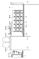
ここで、第1の架台29aと第2の架台29bとが設置された状態の一例としての詳細を、図13〜図15に示す。図13は、函体構造物10の推進を側方から見た図、図14は到達立坑22から架台29を見た図、図15は設置された架台29を平面から透視して示す図である。なお、図13において、パイプ23やFCプレート26は図示が省略されている。
Here, FIG. 13 to FIG. 15 show details as an example of a state in which the
これらの図面に示すように、架台29(第1の架台29a,第2の架台29b)はH形鋼を組み合わせた構造体からなり、適宜配置されたブレース(筋交い)33により構造体の補強がされている。
As shown in these drawings, the gantry 29 (the
そして、図13に示すように、第1の架台29aの底面にはキャスタユニット29a−1が取り付けられており、キャスタユニット29a−1に設けられたキャスタ(図示せず)が前述したレール34上を転がるようになっている。
As shown in FIG. 13, a
さらに、図14に示すように、架台29は、函体構造物10の上部スラブ10aの構築予定位置と外面が一致して並ぶように横方向に配置されたパイプ23を受け取る第1の受取部29−1と、函体構造物10の側板10c,10dの構築予定位置と外面が一致して並ぶように縦方向に配置されたパイプ23を受け取る第2の受取部29−2とを有している。そして、後述のようにして到達立坑22側に押し出されたパイプ23を、第1の受取部29−1では横列で1本ずつ受け取り、第2の受取部29−2では縦列で一括して受け取る。
Further, as shown in FIG. 14, the
さて、このようにして第1の架台29aおよび第2の架台29bの設置が完了したならば(図5)、図6に示すように、推進ジャッキ30を作動させ、刃口28により地山を掘削しながら函体構造物10を発進立坑21側から推進させると、パイプ23は到達立坑22側に移動して行く。これとともに、刃口28によって函体構造物10の両側壁側の地盤が切削され、その土砂が函体構造物10内に取り込まれるので、この土砂を排除しながら推進ジャッキ30によってさらに函体構造物10を押圧する。
Now, when the installation of the
このとき、FCプレート26は土留壁25に固定されているので、パイプ23が到達立坑22側に移動するにも拘わらず、表層部の土砂は移動しない。
At this time, since the
なお、推進ジャッキ30の最大推進ストロークでも函体構造物10が地盤内に埋没しない場合には、最大推進ストロークまで使って函体構造物10を推進させた後、一旦推進ジャッキ30を取り外して反力壁31側にストラット32を設置する。そして、図示するように、あらためてストラット32と函体構造物10との間に推進ジャッキ30を設置し、函体構造物10の推進を再開する。
If the
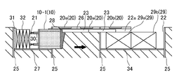
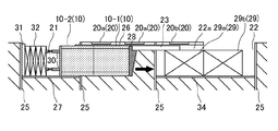
このようにして最初の函体構造物10をFCプレート26に沿って推進させ、図7に示すように、内部土砂を切削しながら到達立坑22側に先頭のパイプ23を排出して函体構造物10と置換するとともに、先に施工された函体構造物10−1の後方に次に施工される函体構造物10−2を設置する。
In this way, the
なお、縦列配置される函体構造物10は、PC鋼棒やPC鋼線などの定着材で相互に定着されることにより、函体構造物10同士のズレが防止される。この定着作業は、次に施工される函体構造物10−2を設置する都度、先に施工された函体構造物10−1との間で行われる。
Note that the
ここで、函体構造物10の推進により到達立坑22に押し出されたパイプ23は、空間22a内に位置する第1の架台29aで一旦受け取られ(図6)、その後、空間22aの外に位置する第2の架台29bへと移動される(図7)。そして、図示しないクレーンで吊り上げられて、到達立坑22から撤去される(図8)(パイプ撤去工程)。
Here, the
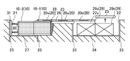
このようにして先頭のパイプ23の撤去が行われたならば、図9に示すように、先に施工された函体構造物10−1の場合と同様にして次に施工される函体構造物10−2を推進し、次のパイプ23を到達立坑22側に押し出す。ここでも、到達立坑22に押し出されたパイプ23は第1の架台29aで一旦受け取られ(図9)、次に第2の架台29bへと移動され(図10)、クレーンで吊り上げられて到達立坑22から撤去される(図11)(パイプ撤去工程)。
If the leading
これら一連の作業を順次繰り返し、最後に刃口28、架台29、推進ジャッキ30、反力壁31、ストラット32、レール34などを撤去することにより、図12に示すように、路線下に函体構造物10が縦列に構築されて地下道が形成される(函体構造物構築工程)。
These series of operations are sequentially repeated, and finally the
以上に示したように、本実施の形態における函体構造物10の設置方法によれば、第1の架台29aを組み立てて到達立坑22側に形成された空間22a内に移動して設置し、第2の架台29bを第1の架台29aに連結して組み立てるようにしているので、到達立坑22側に押し出されたパイプ23を受け取るための架台29を容易に設置することが可能になる。
As described above, according to the installation method of the
なお、パイプ圧入工程、第1の架台組立工程、第1の架台移設工程、第2の架台設置工程、パイプ撤去工程および函体構造物構築工程は、以上に説明した順序で実施されることに限定されるものではなく、各工程を実施する際に前提とされる工程が実施されている限り、どの順序であってもよい。 The pipe press-fitting process, the first gantry assembly process, the first gantry transfer process, the second gantry installation process, the pipe removal process, and the box structure construction process are performed in the order described above. The order is not limited, and any order may be used as long as the processes assumed when the processes are performed are performed.
さて、以上説明した場合には、第1の架台29aを組み立てて空間22a内に移動して設置し、この第1の架台29aに第2の架台29bを連結して組み立てている。しかしながら、第1の架台29aを空間22aに設置したときに、その後端である空間外に位置する部分がパイプ23をクレーンで吊り上げる作業を行う際に必要な長さを有するときには、第1の架台29aのみで到達立坑22における架台29の設置が完了し、第1の架台29aに連結され第2の架台29bは必要がなくなる。
In the case described above, the
この場合、組み立てられた第1の架台29aを、その一部が空間22a内に位置するように移動して設置する。また、発進立坑21側から函体構造物10を推進させてパイプ23を到達立坑22側に押し出したならば、その押し出されたパイプ23を第1の架台29aで受けた後、空間22aを形成する天井面と干渉しない位置まで第1の架台29a上を移動させ、クレーンで吊り上げて到達立坑22から撤去する。
In this case, the assembled
これによっても、第1の架台29aを組み立て、その一部が到達立坑22側に形成された空間22a内に位置するように移動して設置しているので、到達立坑22側に押し出されたパイプ23を受け取るための架台29を容易に設置することが可能になる。
Also by this, the
以上本発明者によってなされた発明を実施の形態に基づき具体的に説明したが、本明細書で開示された実施の形態はすべての点で例示であって、開示された技術に限定されるものではないと考えるべきである。すなわち、本発明の技術的な範囲は、前記の実施の形態における説明に基づいて制限的に解釈されるものでなく、あくまでも特許請求の範囲の記載に従って解釈されるべきであり、特許請求の範囲の記載技術と均等な技術および特許請求の範囲の要旨を逸脱しない限りにおけるすべての変更が含まれる。 Although the invention made by the present inventor has been specifically described based on the embodiment, the embodiment disclosed in this specification is an example in all respects and is limited to the disclosed technology. Should not be considered. That is, the technical scope of the present invention should not be construed restrictively based on the description in the above-described embodiment, but should be construed according to the description of the scope of claims. All modifications are included without departing from the technical scope equivalent to the described technique and the gist of the claims.
例えば、上記説明においては、推進ジャッキ30を用いて函体構造物10を後端側から押圧する場合について述べたが、到達立坑22側から鋼線を埋設して函体構造物10を引っ張る等の方法を採用してもよく、要するに函体構造物10を推進させればよい。
For example, in the above description, the case where the
以上の説明では、本発明による函体構造物の設置方法を、推進工法の一つであるR&C工法に用いた場合が示されているが、R&C工法以外にも、例えばSFT工法やFJ工法など、様々な推進工法に用いることができる。 In the above description, the case where the box structure installation method according to the present invention is used for the R & C method, which is one of the propulsion methods, is shown. However, other than the R & C method, for example, the SFT method, the FJ method, etc. It can be used for various propulsion methods.
10,10−1,10b−2 函体構造物
10a 上部スラブ
10b 下部スラブ
10c,d 側板
10e 開口
10f 定着材挿通孔
10g 溝
10h グラウトホール
20 軌道
21 発進立坑
22 到達立坑
23 パイプ
24 推進機
25 土留壁
26 FCプレート
27 推進台
28 刃口
29 架台
29−1 第1の受取部
29−2 第2の受取部
29a 第1の架台
29a−1 キャスタユニット
29b 第2の架台
30 推進ジャッキ
31 反力壁
32 ストラット
33 ブレース
34 レール
10, 10-1, 10b-2
Claims (3)
前記函体構造物の構築予定位置と外面とが一致して並ぶようにして、複数本のパイプを前記路線を横断する方向に沿って圧入するパイプ圧入工程と、
前記函体構造物と置き換えられて除去された前記パイプを受け取る移動可能な第1の架台を前記空間の外で組み立てる第1の架台組立工程と、
前記第1の架台組立工程で組み立てられた前記第1の架台を、少なくともその一部が前記空間内に位置するように移動して設置する第1の架台移設工程と、
前記函体構造物と置き換えられて除去された前記パイプを受け取る移動不能な第2の架台を、前記第1の架台移設工程で前記空間内に移動された前記第1の架台と接続されるように組み立てて設置する第2の架台設置工程と、
前記発進立坑側から前記函体構造物を推進させて前記パイプを前記到達立坑側に押し出し、当該函体構造物を前記パイプと置換して前記路線下に構築する函体構造物構築工程と、
前記到達立坑側に押し出された前記パイプを前記第1の架台で受けた後、前記空間を形成する天井面と干渉しない位置まで当該第1の架台から前記第2の架台へ向けて移動させて前記到達立坑から撤去するパイプ撤去工程と、
を有することを特徴とする函体構造物の設置方法。 By propelling a hollow box structure having a rectangular cross section from the starting shaft to the reaching shaft, other than the space under the line in which an opening space corresponding to the box structure is formed on the reaching shaft side A box structure installation method in a box propulsion method for building the box structure across the box,
A pipe press-fitting step of press-fitting a plurality of pipes along a direction crossing the line, so that the construction planned position and the outer surface of the box structure are aligned with each other;
A first gantry assembling step of assembling a movable first cradle for receiving the pipe removed by replacing the box structure outside the space;
A first gantry moving step of installing the first gantry assembled in the first gantry assembling step so that at least a part thereof is located in the space; and
The second frame that cannot move and receives the pipe that has been replaced by the box structure is connected to the first frame that has been moved into the space in the first frame moving step. A second pedestal installation step for assembling and installing;
A box structure construction step of propelling the box structure from the start shaft side to push the pipe to the arrival shaft side, replacing the box structure with the pipe and building under the route,
After the pipe pushed out to the reach shaft side is received by the first gantry, the pipe is moved from the first gantry to the second gantry to a position where it does not interfere with the ceiling surface forming the space. A pipe removing step for removing from the shaft,
A method for installing a box structure, comprising:
前記函体構造物の構築予定位置と外面とが一致して並ぶようにして、複数本のパイプを前記路線を横断する方向に沿って圧入するパイプ圧入工程と、
前記函体構造物と置き換えられて除去された前記パイプを受け取る移動可能な第1の架台を前記空間の外で組み立てる第1の架台組立工程と、
前記第1の架台組立工程で組み立てられた前記第1の架台を、その一部が前記空間内に位置するように移動して設置する第1の架台移設工程と、
前記発進立坑側から前記函体構造物を推進させて前記パイプを前記到達立坑側に押し出し、当該函体構造物を前記パイプと置換して前記路線下に構築する函体構造物構築工程と、
前記到達立坑側に押し出された前記パイプを前記第1の架台で受けた後、前記空間を形成する天井面と干渉しない位置まで当該第1の架台上を移動させて前記到達立坑から撤去するパイプ撤去工程と、
を有することを特徴とする函体構造物の設置方法。 By propelling a hollow box structure having a rectangular cross section from the starting shaft to the reaching shaft, other than the space under the line in which an opening space corresponding to the box structure is formed on the reaching shaft side A box structure installation method in a box propulsion method for building the box structure across the box,
A pipe press-fitting step of press-fitting a plurality of pipes along a direction crossing the line, so that the construction planned position and the outer surface of the box structure are aligned with each other;
A first gantry assembling step of assembling a movable first cradle for receiving the pipe removed by replacing the box structure outside the space;
A first gantry moving step of moving and installing the first gantry assembled in the first gantry assembling step so that a part thereof is located in the space;
A box structure construction step of propelling the box structure from the start shaft side to push the pipe to the arrival shaft side, replacing the box structure with the pipe and building under the route,
After receiving the pipe pushed out to the reaching shaft side by the first mount, the pipe is moved on the first mount to a position where it does not interfere with the ceiling surface forming the space and removed from the reaching shaft Removal process,
A method for installing a box structure, comprising:
前記第1の架台移設工程では、前記第1の架台組立工程で組み立てられて前記レール上にある前記第1の架台を、当該レール上を滑動させて前記空間内へ移動する、
ことを特徴とする請求項1または2記載の函体構造物の設置方法。 In the first mount assembly step, the first mount is assembled on a rail;
In the first gantry relocation step, the first gantry assembled on the rail in the first gantry assembling step is slid on the rail and moved into the space.
The box structure installation method according to claim 1 or 2, wherein the box structure is installed.
Priority Applications (1)
| Application Number | Priority Date | Filing Date | Title |
|---|---|---|---|
| JP2012287344A JP6037120B2 (en) | 2012-12-28 | 2012-12-28 | How to install the box structure |
Applications Claiming Priority (1)
| Application Number | Priority Date | Filing Date | Title |
|---|---|---|---|
| JP2012287344A JP6037120B2 (en) | 2012-12-28 | 2012-12-28 | How to install the box structure |
Publications (2)
| Publication Number | Publication Date |
|---|---|
| JP2014129664A true JP2014129664A (en) | 2014-07-10 |
| JP6037120B2 JP6037120B2 (en) | 2016-11-30 |
Family
ID=51408254
Family Applications (1)
| Application Number | Title | Priority Date | Filing Date |
|---|---|---|---|
| JP2012287344A Active JP6037120B2 (en) | 2012-12-28 | 2012-12-28 | How to install the box structure |
Country Status (1)
| Country | Link |
|---|---|
| JP (1) | JP6037120B2 (en) |
Cited By (7)
| Publication number | Priority date | Publication date | Assignee | Title |
|---|---|---|---|---|
| JP2016176257A (en) * | 2015-03-20 | 2016-10-06 | 植村 誠 | Construction method of underground structure |
| JP2017025602A (en) * | 2015-07-23 | 2017-02-02 | 株式会社竹中工務店 | Construction method of new construction object |
| CN106837343A (en) * | 2016-12-16 | 2017-06-13 | 上海市政建设有限公司 | Push pipe goes out the construction method of hole second consolidation |
| CN110359916A (en) * | 2018-03-26 | 2019-10-22 | 植村技研工业株式会社 | The construction method of underground structures |
| JP2020063640A (en) * | 2018-10-19 | 2020-04-23 | 株式会社奥村組 | Spacer and propulsion method for box structure |
| CN111322456A (en) * | 2020-03-31 | 2020-06-23 | 乐剑剑 | Underground pipeline digging-free laying system |
| JP7084515B1 (en) | 2021-01-28 | 2022-06-14 | 誠 植村 | Construction method of underground structure |
Citations (4)
| Publication number | Priority date | Publication date | Assignee | Title |
|---|---|---|---|---|
| JPH06229187A (en) * | 1993-02-01 | 1994-08-16 | Koichi Uemura | Constructing method of subsurface structure |
| JP2002004779A (en) * | 2000-06-19 | 2002-01-09 | Kidoh Construction Co Ltd | Shifter in shaft for pipe jacking |
| JP2005264552A (en) * | 2004-03-18 | 2005-09-29 | Kajima Corp | Tunnel promotion method |
| JP2012202056A (en) * | 2011-03-24 | 2012-10-22 | Okumura Corp | Reaction device |
-
2012
- 2012-12-28 JP JP2012287344A patent/JP6037120B2/en active Active
Patent Citations (4)
| Publication number | Priority date | Publication date | Assignee | Title |
|---|---|---|---|---|
| JPH06229187A (en) * | 1993-02-01 | 1994-08-16 | Koichi Uemura | Constructing method of subsurface structure |
| JP2002004779A (en) * | 2000-06-19 | 2002-01-09 | Kidoh Construction Co Ltd | Shifter in shaft for pipe jacking |
| JP2005264552A (en) * | 2004-03-18 | 2005-09-29 | Kajima Corp | Tunnel promotion method |
| JP2012202056A (en) * | 2011-03-24 | 2012-10-22 | Okumura Corp | Reaction device |
Cited By (11)
| Publication number | Priority date | Publication date | Assignee | Title |
|---|---|---|---|---|
| JP2016176257A (en) * | 2015-03-20 | 2016-10-06 | 植村 誠 | Construction method of underground structure |
| JP2017025602A (en) * | 2015-07-23 | 2017-02-02 | 株式会社竹中工務店 | Construction method of new construction object |
| CN106837343A (en) * | 2016-12-16 | 2017-06-13 | 上海市政建设有限公司 | Push pipe goes out the construction method of hole second consolidation |
| CN106837343B (en) * | 2016-12-16 | 2019-03-01 | 上海市政建设有限公司 | Push pipe goes out the construction method of hole second consolidation |
| CN110359916A (en) * | 2018-03-26 | 2019-10-22 | 植村技研工业株式会社 | The construction method of underground structures |
| CN110359916B (en) * | 2018-03-26 | 2021-05-28 | 植村技研工业株式会社 | Construction method for underground structure |
| JP2020063640A (en) * | 2018-10-19 | 2020-04-23 | 株式会社奥村組 | Spacer and propulsion method for box structure |
| JP7160239B2 (en) | 2018-10-19 | 2022-10-25 | 株式会社奥村組 | Propulsion method of box structure |
| CN111322456A (en) * | 2020-03-31 | 2020-06-23 | 乐剑剑 | Underground pipeline digging-free laying system |
| JP7084515B1 (en) | 2021-01-28 | 2022-06-14 | 誠 植村 | Construction method of underground structure |
| JP2022115312A (en) * | 2021-01-28 | 2022-08-09 | 誠 植村 | Construction method for underground structures |
Also Published As
| Publication number | Publication date |
|---|---|
| JP6037120B2 (en) | 2016-11-30 |
Similar Documents
| Publication | Publication Date | Title |
|---|---|---|
| JP6037120B2 (en) | How to install the box structure | |
| KR101269597B1 (en) | Underground structure construction method | |
| JP6289045B2 (en) | How to build a shield tunnel | |
| JP5874890B2 (en) | How to install the box structure | |
| JP7160239B2 (en) | Propulsion method of box structure | |
| JP5885229B2 (en) | Reaction force device | |
| JP6266411B2 (en) | Ground excavation method | |
| JPH01304297A (en) | Reconstruction of existing underground structure | |
| JP6982603B2 (en) | Box-shaped roof construction method | |
| JP7032736B2 (en) | How to install FC plate fixing member and box structure | |
| JP5054164B2 (en) | Construction method for underground structures | |
| JP2010150809A (en) | Thrust transfer member for caisson, and method for constructing underground structure using the same | |
| JP4926092B2 (en) | How to build a box structure | |
| JP5342571B2 (en) | How to build an underpass | |
| JP3116098B2 (en) | Construction method for underground structures | |
| JP5976728B2 (en) | Widening method for existing structures | |
| JP6441871B2 (en) | Box roof deflection reduction method for box roof method | |
| JP2016223262A (en) | Removal method of existing structure | |
| JP4581419B2 (en) | Seismic isolation zone | |
| JP2876435B2 (en) | How to build underground structures | |
| JP4926093B2 (en) | How to build a box structure | |
| JP2020066923A (en) | Construction method of underground structure | |
| JP2023116382A (en) | Box connection structure and connection box construction method | |
| JP2024143685A (en) | Underpass construction method and underground passage structure | |
| JP2024143678A (en) | Underpass construction method |
Legal Events
| Date | Code | Title | Description |
|---|---|---|---|
| A621 | Written request for application examination |
Free format text: JAPANESE INTERMEDIATE CODE: A621 Effective date: 20151030 |
|
| A977 | Report on retrieval |
Free format text: JAPANESE INTERMEDIATE CODE: A971007 Effective date: 20161007 |
|
| TRDD | Decision of grant or rejection written | ||
| A01 | Written decision to grant a patent or to grant a registration (utility model) |
Free format text: JAPANESE INTERMEDIATE CODE: A01 Effective date: 20161013 |
|
| A61 | First payment of annual fees (during grant procedure) |
Free format text: JAPANESE INTERMEDIATE CODE: A61 Effective date: 20161018 |
|
| R150 | Certificate of patent or registration of utility model |
Ref document number: 6037120 Country of ref document: JP Free format text: JAPANESE INTERMEDIATE CODE: R150 |
|
| R250 | Receipt of annual fees |
Free format text: JAPANESE INTERMEDIATE CODE: R250 |
|
| R250 | Receipt of annual fees |
Free format text: JAPANESE INTERMEDIATE CODE: R250 |