JP2014123020A - Actuator, optical scanner, image display apparatus and head-mounted display - Google Patents
Actuator, optical scanner, image display apparatus and head-mounted display Download PDFInfo
- Publication number
- JP2014123020A JP2014123020A JP2012279066A JP2012279066A JP2014123020A JP 2014123020 A JP2014123020 A JP 2014123020A JP 2012279066 A JP2012279066 A JP 2012279066A JP 2012279066 A JP2012279066 A JP 2012279066A JP 2014123020 A JP2014123020 A JP 2014123020A
- Authority
- JP
- Japan
- Prior art keywords
- reflecting
- axis
- plate
- movable
- actuator
- Prior art date
- Legal status (The legal status is an assumption and is not a legal conclusion. Google has not performed a legal analysis and makes no representation as to the accuracy of the status listed.)
- Withdrawn
Links
Images


Classifications
-
- G—PHYSICS
- G02—OPTICS
- G02B—OPTICAL ELEMENTS, SYSTEMS OR APPARATUS
- G02B26/00—Optical devices or arrangements for the control of light using movable or deformable optical elements
- G02B26/08—Optical devices or arrangements for the control of light using movable or deformable optical elements for controlling the direction of light
- G02B26/10—Scanning systems
- G02B26/105—Scanning systems with one or more pivoting mirrors or galvano-mirrors
-
- G—PHYSICS
- G02—OPTICS
- G02B—OPTICAL ELEMENTS, SYSTEMS OR APPARATUS
- G02B26/00—Optical devices or arrangements for the control of light using movable or deformable optical elements
- G02B26/08—Optical devices or arrangements for the control of light using movable or deformable optical elements for controlling the direction of light
- G02B26/10—Scanning systems
-
- G—PHYSICS
- G02—OPTICS
- G02B—OPTICAL ELEMENTS, SYSTEMS OR APPARATUS
- G02B27/00—Optical systems or apparatus not provided for by any of the groups G02B1/00 - G02B26/00, G02B30/00
- G02B27/01—Head-up displays
- G02B27/0149—Head-up displays characterised by mechanical features
Abstract
Description
本発明は、アクチュエーター、光スキャナー、画像表示装置、ヘッドマウントディスプレイに関する。 The present invention relates to an actuator, an optical scanner, an image display device, and a head mounted display.
従来、板状の取付部と当該取付部を支持する軸部と、取付部の一方の面に設けられた磁石と、取付部の他方の面に設けられた光反射部材と、を備えた光学デバイスが知られている(例えば、特許文献1参照)。 Conventionally, an optical device including a plate-shaped mounting portion, a shaft portion that supports the mounting portion, a magnet provided on one surface of the mounting portion, and a light reflecting member provided on the other surface of the mounting portion. A device is known (see, for example, Patent Document 1).
しかしながら、上記の光学デバイスでは、光反射部材を所定軸周りに揺動した際、光反射部材が撓む、という課題があった。 However, the above optical device has a problem that the light reflecting member bends when the light reflecting member is swung around a predetermined axis.
本発明は、上述の課題の少なくとも一部を解決するためになされたものであり、以下の形態または適用例として実現することが可能である。 SUMMARY An advantage of some aspects of the invention is to solve at least a part of the problems described above, and the invention can be implemented as the following forms or application examples.
[適用例1]本適用例にかかるアクチュエーターは、可動部と、前記可動部を第1軸周りに揺動可能に支持する第1軸部と、光を反射する反射面を有する反射板、前記反射板の前記反射面と反対側の面に設けられた支柱、を備え、前記可動部に前記支柱が固着された反射部と、を有し、前記反射板の前記反射面と反対側の面にリブが設けられたことを備えたことを特徴とする。 Application Example 1 An actuator according to this application example includes a movable portion, a first shaft portion that supports the movable portion so as to be swingable about a first axis, a reflector having a reflective surface that reflects light, A reflector provided on a surface of the reflecting plate opposite to the reflecting surface, and a reflecting portion having the supporting column fixed to the movable portion, and a surface of the reflecting plate opposite to the reflecting surface It is characterized in that it is provided with a rib.
この構成によれば、可動部の揺動に伴って反射部が揺動する際、反射板の反射面と反対側の面に設けられたリブにより反射板の撓みを抑制することができる。これにより、反射板を安定して動作させることができる。 According to this configuration, when the reflecting portion swings along with the swing of the movable portion, the deflection of the reflecting plate can be suppressed by the rib provided on the surface opposite to the reflecting surface of the reflecting plate. Thereby, a reflector can be operated stably.
[適用例2]上記適用例にかかるアクチュエーターの前記リブは、前記支柱を中心とする円形状であることを特徴とする。 Application Example 2 The rib of the actuator according to the application example described above is characterized in that it has a circular shape centered on the support column.
この構成によれば、可動部の揺動に伴って反射部が揺動する際、反射板の反射面と反対側の面に設けられた円形状のリブにより反射板の撓みを抑制することができる。これにより、反射板を安定して動作させることができる。 According to this configuration, when the reflecting portion swings along with the swing of the movable portion, it is possible to suppress the bending of the reflecting plate by the circular rib provided on the surface opposite to the reflecting surface of the reflecting plate. it can. Thereby, a reflector can be operated stably.
[適用例3]上記適用例にかかるアクチュエーターの前記リブは、前記支柱を中心とする円弧を含む扇形状であることを特徴とする。 Application Example 3 The rib of the actuator according to the application example described above is characterized in that it has a fan shape including an arc centered on the support column.
この構成によれば、可動部の揺動に伴って反射部が揺動する際、反射板の反射面と反対側の面に設けられた扇形状のリブにより反射板の撓みを抑制することができる。これにより、反射板を安定して動作させることができる。 According to this configuration, when the reflecting portion swings with the swing of the movable portion, it is possible to suppress the bending of the reflecting plate by the fan-shaped rib provided on the surface opposite to the reflecting surface of the reflecting plate. it can. Thereby, a reflector can be operated stably.
[適用例4]上記適用例にかかるアクチュエーターの前記反射板は、平面視において円形状を有し、前記リブは、前記反射板の前記反射面と反対側の面における前記支柱の中心から前記反射板の半径の1/2以内の領域に設けられたことを特徴とする。 Application Example 4 The reflector of the actuator according to the application example has a circular shape in a plan view, and the rib is reflected from the center of the support column on the surface of the reflector opposite to the reflection surface. It is characterized by being provided in a region within 1/2 of the radius of the plate.
この構成によれば、効率よく反射板の撓みを抑制させることができる。 According to this structure, the bending of a reflecting plate can be suppressed efficiently.
[適用例5]上記適用例にかかるアクチュエーターでは、前記反射板の半径の1/2以内の領域から前記反射板の外周部に向けて延在するリブをさらに設けたことを特徴とする。 Application Example 5 The actuator according to the application example described above is characterized in that a rib extending from an area within a half of the radius of the reflecting plate toward the outer peripheral portion of the reflecting plate is further provided.
この構成によれば、さらに効率よく反射板の撓みを抑制させることができる。 According to this configuration, it is possible to more efficiently suppress the bending of the reflecting plate.
[適用例6]上記適用例にかかるアクチュエーターでは、前記リブは、前記反射板の板厚方向からの平面視において前記第1軸に対して対称に設けられたことを特徴とする。 Application Example 6 In the actuator according to the application example, the rib is provided symmetrically with respect to the first axis in a plan view from the thickness direction of the reflection plate.
この構成よれば、第1軸部周りにバランスよく反射部を揺動させることができる。 According to this configuration, the reflecting portion can be swung in a well-balanced manner around the first shaft portion.
[適用例7]上記適用例にかかるアクチュエーターは、前記第1軸部と接続され、かつ、前記可動部を取り囲む形状の可動枠と、前記第1軸に交差する第2軸周りに前記可動枠を揺動可能に支持する第2軸部と、を含むことを特徴とする。 Application Example 7 The actuator according to the application example described above includes a movable frame that is connected to the first shaft part and surrounds the movable part, and the movable frame around a second axis that intersects the first axis. And a second shaft portion that supports the shaft in a swingable manner.
この構成によれば、第1軸周り及び第2軸周りに反射部が揺動する際、反射板の反射面と反対側の面に設けられたリブにより反射板の撓みを抑制することができる。これにより、反射板を安定して動作させることができる。 According to this configuration, when the reflecting portion swings around the first axis and around the second axis, the deflection of the reflecting plate can be suppressed by the rib provided on the surface opposite to the reflecting surface of the reflecting plate. . Thereby, a reflector can be operated stably.
[適用例8]本適用例にかかる光スキャナーは、可動部と、前記可動部を第1軸周りに揺動可能に支持する第1軸部と、光を反射する反射面を有する反射板、前記反射板の前記反射面と反対側の裏面に設けられた支柱、を備え、前記可動部に前記支柱が固着された反射部と、を有し、前記反射部の前記反射面と反対側の面にリブが設けられたことを備えたことを特徴とする。 Application Example 8 An optical scanner according to this application example includes a movable portion, a first shaft portion that supports the movable portion so as to be able to swing around the first axis, and a reflector having a reflective surface that reflects light, A reflector provided on the back surface of the reflector opposite to the reflecting surface, and a reflecting portion to which the pillar is fixed to the movable portion, and the reflector on the side opposite to the reflecting surface. A feature is that a rib is provided on the surface.
この構成によれば、可動部の揺動に伴って反射部が揺動する際、反射板の反射面と反対側の面に設けられたリブにより反射板の撓みを抑制することができる。これにより、反射板を安定して動作させることができる。 According to this configuration, when the reflecting portion swings along with the swing of the movable portion, the deflection of the reflecting plate can be suppressed by the rib provided on the surface opposite to the reflecting surface of the reflecting plate. Thereby, a reflector can be operated stably.
[適用例9]本適用例にかかる画像表示装置は、可動部と、前記可動部を第1軸周りに揺動可能に支持する第1軸部と、光を反射する反射面を有する反射板および前記反射板の前記反射面と反対側の裏面に設けられた支柱を備え、前記可動部に前記支柱が固着された反射部と、を有し、前記反射板の前記反射面と反対側の面にリブが設けられたアクチュエーターと、前記アクチュエーターに対して光を照射する照射部と、を備えたことを特徴とする。 Application Example 9 An image display apparatus according to this application example includes a movable portion, a first shaft portion that supports the movable portion so as to be swingable about the first axis, and a reflecting plate having a reflecting surface that reflects light. And a reflector provided on the back surface opposite to the reflecting surface of the reflector, and a reflecting portion to which the pillar is fixed to the movable portion, and on the side opposite to the reflecting surface of the reflector An actuator having ribs on the surface, and an irradiation unit that irradiates light to the actuator.
この構成によれば、反射板の揺動時における撓みが低減されたアクチュエーターが搭載されるため、画像品質を向上させることができる。 According to this configuration, since the actuator with reduced bending when the reflecting plate is swung is mounted, the image quality can be improved.
[適用例10]本適用例にかかるヘッドマウントディスプレイは、可動部と、前記可動部を第1軸周りに揺動可能に支持する第1軸部と、光を反射する反射面を有する反射板および前記反射板の前記反射面と反対側の裏面に設けられた支柱を備え、前記可動部に前記支柱が固着された反射部と、を有し、前記反射板の前記反射面と反対側の面にリブが設けられたアクチュエーターと、前記光スキャナーに対して光を照射する照射部と、を備えたことを特徴とする。 Application Example 10 A head-mounted display according to this application example includes a movable portion, a first shaft portion that supports the movable portion so as to be swingable about the first axis, and a reflecting plate having a reflecting surface that reflects light. And a reflector provided on the back surface opposite to the reflecting surface of the reflector, and a reflecting portion to which the pillar is fixed to the movable portion, and on the side opposite to the reflecting surface of the reflector An actuator having ribs on the surface, and an irradiating unit for irradiating light to the optical scanner are provided.
この構成によれば、反射板の揺動時における撓みが低減されたアクチュエーターが搭載されるため、画像品質を向上させることができる。 According to this configuration, since the actuator with reduced bending when the reflecting plate is swung is mounted, the image quality can be improved.
以下、本発明の実施形態について、図面を参照して説明する。なお、以下の各図においては、各部材等を認識可能な程度の大きさにするため、各部材等の尺度を実際とは異ならせて示している。 Hereinafter, embodiments of the present invention will be described with reference to the drawings. In the following drawings, the scale of each member or the like is shown differently from the actual scale so as to make each member or the like recognizable.
[第1実施形態]
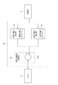
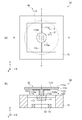
まず、アクチュエーターの構成について説明する。なお、本実施形態では、アクチュエーターとしての光スキャナーを例に挙げて説明する。光スキャナーは、可動部と、可動部を第1軸周りに揺動可能に支持する第1軸部と、反射面を有する反射板と反射板の反射面と反対側の面に設けられた支柱とを備え、可動部に支柱が固着された反射部と、を有し、反射板の反射面と反対側の面にリブが設けられたものである。図1は、本実施形態にかかる光スキャナーの構成を示し、図1(a)は平面図であり、図1(b)は図1(a)におけるX−X断面図である。なお、図1(a)は反射部を透視した場合の平面図である。また、図2は反射部の平面図である。以下、具体的に説明する。
[First Embodiment]
First, the configuration of the actuator will be described. In the present embodiment, an optical scanner as an actuator will be described as an example. The optical scanner includes a movable portion, a first shaft portion that supports the movable portion so as to be swingable about a first axis, a reflecting plate having a reflecting surface, and a column provided on a surface opposite to the reflecting surface of the reflecting plate. And a reflecting part having a support fixed to the movable part, and a rib is provided on the surface of the reflecting plate opposite to the reflecting surface. 1A and 1B show a configuration of an optical scanner according to the present embodiment, in which FIG. 1A is a plan view, and FIG. 1B is a sectional view taken along line XX in FIG. FIG. 1A is a plan view when the reflecting portion is seen through. FIG. 2 is a plan view of the reflecting portion. This will be specifically described below.
光スキャナー1の可動部2は、可動板111を含み、軸部3は、一対の軸部(第1軸部)11a,11bを含んでいる。また、可動板111の板厚方向から見て、可動板111の周辺を囲むように外枠支持部15が配置され、可動板111は、軸部11a,11bを介して外枠支持部15に接続されている。軸部11a,11b弾性変形可能である。そして、可動板111を第1軸周り(本実施形態ではY軸周り)に揺動(回動)可能となるように、可動板111と外枠支持部15とが軸部11a,11bを介して連結されている。
The
軸部11a,11bは、可動板111を介して互いに対向するように配置されている。また、軸部11a,11bは、それぞれ、Y軸に沿った方向に延在する長手形状を成す。そして、軸部11a,11bは、それぞれ、一端部が可動板111に接続され、他端部が外枠支持部15に接続されている。そして、軸部11a,11bは、それぞれ、中心軸とY軸とが一致するように配置されている。このように構成された軸部11a,11bは、それぞれ、可動板111によるY軸周りの揺動に伴ってねじれ変形する。なお、軸部11a,11bの形態は上記の形態に限定されない。例えば、途中の少なくとも1箇所が屈曲または湾曲した、ミアンダー形状を有していてもよい。また、軸部11a,11bの軸の本数に関して単数であってもよいし、複数であってもよい。可動板111、軸部11a,11b及び外枠支持部15は、例えば、シリコン単結晶の基板を用いて一体的に形成されている。
The
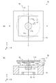
反射部4は、反射板113と支柱115とを備えている。本実施形態の反射板113は、板状を成すととともに、反射板113の板厚方向からの平面視(以下、単に「平面視」ともいう)において円形状を成している。なお、反射板113の平面視における形状は、楕円形状であってもよい。反射板113が楕円形状の場合、X軸方向を短軸方向または長軸方向とすることができる。反射板113の第1面113aには光を反射させる反射面114が形成されている。また、反射板113の第1面113aとは反対側の面となる第2面113bには支柱115が配置されている。そして、支柱115の反射板113側とは反対側の面と可動板111とが固着されている。固着方法としては、例えば、各種接着剤やろう材等の接合材を用いて固着させることができる。このように、本実施形態では、可動板111と反射板113とが別部材として構成されている。このようにすれば、可動板111等の小型化の影響を受けずに、反射部4の大きさを維持することができる。また、可動板111と反射板113とが離間する構成となるため、反射板113が軸部11a、11bの側面に直接接続されないので、反射板113が揺動(回動)するときに、軸部11a、11bの捩れ変形による応力が反射板113に及ぶのを防止または抑制することができる。反射板113と支柱115とは、シリコン単結晶の基板を用いて一体的に形成されている。なお、反射板113と支柱115とを別々に形成したのちに、互いに接着してもよい。
The
また、反射板113の第2面113bにはリブ120が設けられている。リブ120は、反射部4が揺動した際の反射板113の撓みを抑制する他の部分よりも厚みの大きい部分であり、いわゆる補強リブとも言われるものである。そして反射板113は、リブ120が形成された厚い部分とリブ120が形成されていない薄い部分とを有する。このことは、反射板113に対して溝が形成された薄い部分と溝が形成されていない厚い部分とを有することと同義である。
Further, a
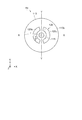
本実施形態では、図2に示すように、反射部4の反射板113の第2面113bには、支柱115を中心とする円形状のリブ120aが設けられている。また、リブ120aは、平面視において、反射板113の第2面113bにおける支柱115の中心から反射板113の半径rの1/2以内の領域に設けられている。なお、反射板113が楕円形状である場合、リブ120aは、平面視において、反射板113の長径の半分を長径とし反射板113の短径の半分を短径とする楕円形状の内側に配置される。
In the present embodiment, as shown in FIG. 2, a
さらに、本実施形態では、反射板113の半径rの1/2以内の領域から反射板113の外周部に向けて部分的に延在するリブ120bが設けられている。外周部に向けて延在するリブ120bは、揺動軸(Y軸)に対してθ=0°〜90°の範囲に配置可能である。本実施形態では、揺動軸(Y軸)に対してθ=45°の位置に配置されている。そして、平面視において所定軸(Y軸)に対して対称となるようにリブ120(120a,120b)が設けられている。なお、図2においてリブ120の配置が理解しやすいようにハッチングを施している。
Furthermore, in the present embodiment, a
また、図1(a)に示すように、反射板113は、平面視において、可動板111及び軸部11a,11bを覆うように配置されている。そのため、軸部11aと軸部11bとの間の距離を短くしつつ、反射部4の面積を大きくすることができる。また、軸部11aと軸部11bとの間の距離を短くすることができることから、外枠支持部15の小型化を図ることができる。これにより、反射板113の面積を大きく維持しつつ、光スキャナー1の全体構造を小型化させることが可能となる。また、不要な光が可動板111及び軸部11a,11bで反射して迷光となるのを防止することができる。また、外枠支持部15の表面には、反射防止処理が施されているのが好ましい。これにより、外枠支持部15に照射された不要光が迷光となるのを防止することができる。かかる反射防止処理としては、特に限定されないが、例えば、反射防止膜(誘電体多層膜)の形成、粗面化処理、黒色処理等が挙げられる。なお、外枠支持部15の他に可動板111や軸部11a,11b等の表面にも反射防止処理を施してもよい。
Moreover, as shown to Fig.1 (a), the reflecting
可動板111の支柱115と固着された面と反対側の面には接着剤等を介して永久磁石21が接合されている。そして、永久磁石21は、平面視において所定軸(Y軸)に対して直交する方向(X軸方向)にN極とS極とに磁化されている。すなわち、永久磁石21は、Y軸を介して対向した互いに極性の異なる一対の磁極を有している。
A
永久磁石21の下方にはコイル31が配置されている。すなわち、永久磁石21に対向するようにコイル31が設けられている。本実施形態では、コイル31が磁心32の外周に沿って巻かれている。そして、コイル31は電圧印加手段(図示せず)に電気的に接続されている。
A
次に、光スキャナー1の動作方法について説明する。まず、電圧印加手段からコイル31に対して所定周波数の交流電流が供給される。これにより、コイル31は上方(可動板111側)に向く磁界と、下方に向く磁界とを交互に発生させる。これにより、コイル31に対して磁石21の一対の磁極のうち一方の磁極が接近し他方の磁極が離間する。こうして、軸部11a,11bをねじれ変形させながら、可動板111と可動板111に固着された反射部4及び磁石21とが、所定軸としてのY軸周りに揺動する。
Next, an operation method of the
なお、コイル31に供給される交流電流の所定周波数は、反射部4、軸部11a,11b及び磁石21から構成される振動系の振動数(ねじり共振周波数)とほぼ一致するように設定するのが好ましい。このように共振を利用することで、可動板111を所定軸(Y軸)周りに揺動させるときに、少ない消費電力で振れ角を大きくすることができる。
The predetermined frequency of the alternating current supplied to the
なお、本実施形態では、磁石21とコイル31と間の電磁力を利用した駆動方式を示したが、これに限定されず、強磁性体に相当する磁石21と、磁界発生手段に相当するコイル31及び電源との間に駆動力を発生させるように構成されていればよい。例えば、コイル31が可動板111に設けられた、いわゆるムービングコイル型の駆動方式であってもよい。
In the present embodiment, the driving method using the electromagnetic force between the
以上、上記第1実施形態によれば、以下の効果を得ることができる。 As described above, according to the first embodiment, the following effects can be obtained.
反射板113の第2面113bには、支柱115を中心とするリブ120a及び反射板113の中心部から反射板113の外周方向に向けて延在するリブ120bが形成されているので、可動板111の揺動に伴って反射板113が揺動される際、反射板113の撓みを抑制することができる。
The
[第2実施形態]
次に、第2実施形態にかかるアクチュエーターの構成について説明する。なお、本実施形態では、アクチュエーターとしての光スキャナーを例に挙げて説明する。本実施形態の光スキャナーは、可動部と、可動部を第1軸周りに揺動可能に支持する第1軸部と、反射面を有する反射板と反射板の反射面と反対側の面に設けられた支柱とを備え、可動部に支柱が固着された反射部と、を有し、反射部の反射板と反対側の面にリブが設けられたことを備えたものである。さらに、本実施形態の光スキャナー1aは、第1軸部と接続され、かつ、可動部を取り囲む枠状の可動枠と、第1軸に交差する第2軸周りに可動枠を揺動可能に支持する第2軸部と、を含むものである。
[Second Embodiment]
Next, the configuration of the actuator according to the second embodiment will be described. In the present embodiment, an optical scanner as an actuator will be described as an example. The optical scanner of the present embodiment has a movable portion, a first shaft portion that supports the movable portion so as to be swingable around the first axis, a reflecting plate having a reflecting surface, and a surface opposite to the reflecting surface of the reflecting plate. And a reflecting portion having the movable column fixed to the movable portion, and a rib provided on the surface of the reflecting portion opposite to the reflecting plate. Furthermore, the
図3は、本実施形態にかかる光スキャナーの構成を示す概略図であり、図3(a)は、反射部を透視した平面図であり、図3(b)は、図3(a)におけるA−A断面図である。なお、第1実施形態と同じ部材等には同じ符号を付している。なお、本実施形態にかかる反射部4の構成は第1実施形態と同様なので説明を省略する(図2参照)。以下、具体的に説明する。
FIG. 3 is a schematic diagram illustrating a configuration of the optical scanner according to the present embodiment, FIG. 3A is a plan view of the reflective portion, and FIG. 3B is a plan view of FIG. It is AA sectional drawing. In addition, the same code | symbol is attached | subjected to the same member etc. as 1st Embodiment. In addition, since the structure of the
本実施形態にかかる光スキャナー1aの可動部2は、可動板111を含み、軸部3は、一対の第1軸部12a,12bを含んでいる。図3(a)に示すように、可動板111は、平面視において円形を有し、光スキャナー1aの中心部に配置されている。可動枠13は、枠状を成し、可動板111の板厚方向から見て可動板111の周囲を囲むように設けられている。換言すれば、可動板111は、枠状の可動枠13の内側に設けられている。そして、可動板111は第1軸部12a,12bを介して可動枠13と接続されている。
The
外枠支持部15は、枠状を成し、可動板111の板厚方向から見て可動枠13の周囲を囲むように設けられている。換言すれば、可動枠13は、外枠支持部15の内側に設けられている。可動枠13は、第2軸部14a,14bを介して外枠支持部15に接続されている。
The outer
第1軸部12a,12b及び第2軸部14a,14bは、それぞれ、弾性変形可能である。そして、第1軸部12a,12bは、可動板111を第1軸周り(本実施形態ではY軸周り)に回動(揺動)可能とするように、可動板111と可動枠13とを連結している。また、第2軸部14a,14bは、可動枠13を第1軸に直交する第2軸周り(本実施形態ではX軸周り)に回動(揺動)可能とするように、可動枠13と外枠支持部15とを連結している。
The
第1軸部12a,12bは、可動板111を介して互いに対向するように配置されている。また、第1軸部12a,12bは、それぞれ、Y軸に沿った方向に延在する長手形状を成す。そして、第1軸部12a,12bは、それぞれ、一端部が可動板111に接続され、他端部が可動枠13に接続されている。また、第1軸部12a,12bは、それぞれ、中心軸とY軸とが一致するように配置されている。このように構成された第1軸部12a,12bは、それぞれ、可動板111のY軸周りの揺動に伴ってねじれ変形する。
The
第2軸部14a,14bは、可動枠13を介して互いに対向するように配置されている。また、第2軸部14a,14bは、それぞれ、X軸に沿った方向に延在する長手形状を成す。そして、第2軸部14a,14bは、それぞれ、一端部が可動枠13に接続され、他端部が外枠支持部15に接続されている。このように構成された第2軸部14a,14bは、可動枠13のX軸周りの揺動に伴って、第2軸部14a,14b全体がそれぞれねじれ変形する。このように、可動板111をY軸周りに揺動可能とするとともに、可動枠13をX軸周りに揺動可能とすることによりX軸及びY軸の2軸周りに揺動(回動)させることができる。
The
なお、第1軸部12a,12b及び第2軸部14a,14bの形態は上記の形態に限定されない。例えば、途中の少なくとも1箇所が屈曲または湾曲した、ミアンダー形状を有していてもよい。また、第1軸部12a,12bや第2軸部14a,14bの軸の本数に関しても単数であってもよいし、複数であってもよい。なお、可動板111、可動枠13、第1軸部12a,12b、第2軸部14a,14b及び外枠支持部15は、例えば、シリコン単結晶の基板を用いて一体的に形成されている。
In addition, the form of 1st
図3(a)に示すように、反射部4の反射板113は、平面視において、可動部2を覆うように形成されている。すなわち、平面視において、可動板111、第1軸部12a,12b、可動枠13、第2軸部14a,14bが反射板113の内側に配置されている。そのため第1軸部12aと第1軸部12bとの間の距離を短くしつつ、反射板113の面積を大きくすることができる。また、第1軸部12aと第1軸部12bとの間の距離を短くすることができることから、可動枠13の小型化を図ることができる。さらに、可動枠13の小型化を図ることができることから、第2軸部14aと第2軸部14bとの間の距離を短くすることができる。これにより、反射板113の面積を大きく維持しつつも、光スキャナー1の全体構造を小型化させることが可能となる。また、不要な光が可動板111、第1軸部12a,12b、可動枠13及び第2軸部14a,14bで反射して迷光となるのを防止することができる。また、外枠支持部15の表面には、反射防止処理が施されているのが好ましい。これにより、外枠支持部15に照射された不要光が迷光となるのを防止することができる。かかる反射防止処理としては、特に限定されないが、例えば、反射防止膜(誘電体多層膜)の形成、粗面化処理、黒色処理等が挙げられる。なお、外枠支持部15の他に可動板111、第1軸部12a,12b、可動枠13や第2軸部14a,14b等の表面にも反射防止処理を施してもよい。
As shown in FIG. 3A, the reflecting
可動板111の支柱115と固着された面と反対側の面に対向するように永久磁石21aが配置されている。磁石21aは、長手形状を成し、可動枠13の一方の面にスペーサー80を介して接合されている。可動枠13とスペーサー80との接合及びスペーサー80と磁石21aとの接合は接着剤等が適用される。可動枠13と永久磁石21aとの間にスペーサー80を介在させることにより、可動板111と永久磁石21aとの間に空間が形成される。そして当該空間の形成により、可動板111の揺動の際に、可動板111と永久磁石21aとの干渉を防止することができる。
磁石21aの下方にはコイル31が配置されている。すなわち、永久磁石21aに対向するようにコイル31が設けられている。本実施形態では、コイル31が磁心32の外周に沿って巻かれている。そして、コイル31は電圧印加部40に電気的に接続されている。
A
次に、電圧印加部の構成について説明する。図4は、電圧印加部の構成を示すブロック図であり、図5は、発生電圧の一例を示す説明図である。 Next, the configuration of the voltage application unit will be described. FIG. 4 is a block diagram illustrating the configuration of the voltage application unit, and FIG. 5 is an explanatory diagram illustrating an example of the generated voltage.
図4に示すように、電圧印加部40は、可動板111をY軸周りに揺動させるための第1電圧V1を発生させる第1電圧発生部41と、可動板111をX軸周りに揺動させるための第2電圧V2を発生させる第2電圧発生部42と、第1電圧V1と第2電圧V2とを重畳する電圧重畳部43とを備えている。電圧印加部40の第1電圧発生部41及び第2電圧発生部42はそれぞれ制御部7に接続されている。また、電圧印加部40は、コイル31に電気的に接続されており、電圧重畳部43で重畳した電圧をコイル31に印加するように構成されている。
As shown in FIG. 4, the
第1電圧発生部41は、図5(a)に示すように、周期T1で周期的に変化する第1電圧V1(水平走査用電圧)を発生させるものである。すなわち、第1電圧発生部41は、第1周波数(1/T1)の第1電圧V1を発生させるものである。第1電圧V1は、正弦波のような波形を成している。そのため、光スキャナー1は効果的に光を主走査することができる。なお、第1電圧V1の波形は、これに限定されない。
As shown in FIG. 5A, the
また、第1周波数(1/T1)は、水平走査に適した周波数であれば、特に限定されないが、10〜40kHzであるのが好ましい。本実施形態では、第1周波数は、可動板111、第1軸部12a、12bで構成される第1の振動系(ねじり振動系)のねじり共振周波数(f1)と等しくなるように設定されている。つまり、第1の振動系は、そのねじり共振周波数f1が水平走査に適した周波数になるように設計(製造)されている。これにより、可動板111のY軸周りの回動角を大きくすることができる。
The first frequency (1 / T1) is not particularly limited as long as it is suitable for horizontal scanning, but is preferably 10 to 40 kHz. In the present embodiment, the first frequency is set to be equal to the torsional resonance frequency (f1) of the first vibration system (torsional vibration system) composed of the
一方、第2電圧発生部42は、図5(b)に示すように、周期T1と異なる周期T2で周期的に変化する第2電圧V2(垂直走査用電圧)を発生させるものである。すなわち、第2電圧発生部42は、第2周波数(1/T2)の第2電圧V2を発生させるものである。第2電圧V2は、鋸波のような波形を成している。そのため、光スキャナー1は効果的に光を垂直走査(副走査)することができる。なお、第2電圧V2の波形は、これに限定されない。
On the other hand, as shown in FIG. 5B, the
第2周波数(1/T2)は、第1周波数(1/T1)と異なり、かつ、垂直走査に適した周波数であれば、特に限定されないが、30〜120Hzであるのが好ましい。さらに、60Hz程度が好適である。このように、第2電圧V2の周波数を60Hz程度とし、前述したように第1電圧V1の周波数を10〜40kHzとすることで、ディスプレイでの描画に適した周波数で、可動板111を互いに直交する2軸(X軸及びY軸)のそれぞれの軸周りに回動させることができる。ただし、可動板111をX軸及びY軸のそれぞれの軸周りに回動させることができれば、第1電圧V1の周波数と第2電圧V2の周波数との組み合わせは、特に限定されない。
The second frequency (1 / T2) is not particularly limited as long as it is different from the first frequency (1 / T1) and is suitable for vertical scanning, but is preferably 30 to 120 Hz. Furthermore, about 60 Hz is suitable. Thus, by setting the frequency of the second voltage V2 to about 60 Hz and the frequency of the first voltage V1 to 10 to 40 kHz as described above, the
本実施形態では、第2電圧V2の周波数は、可動板111、第1軸部12a、12b、可動枠13、第2軸部14a,14b,14c,14dで構成された第2の振動系(ねじり振動系)のねじり共振周波数(共振周波数)と異なる周波数となるように調整されている。このような第2電圧V2の周波数(第2周波数)は、第1電圧V1の周波数(第1周波数)よりも小さいことが好ましい。すなわち、周期T2は、周期T1よりも長いことが好ましい。これにより、より確実かつより円滑に、可動板111をY軸周りに第1周波数で回動させつつ、X軸周りに第2周波数で回動させることができる。
In the present embodiment, the frequency of the second voltage V2 is the second vibration system (including the
また、第1の振動系のねじり共振周波数をf1[Hz]とし、第2の振動系のねじり共振周波数をf2[Hz]としたとき、f1とf2とが、f2<f1の関係を満たすことが好ましく、f1≧10f2の関係を満たすことがより好ましい。これにより、より円滑に、可動板111を、Y軸周りに第1電圧V1の周波数で回動させつつ、X軸周りに第2電圧V2の周波数で回動させることができる。
Further, when the torsional resonance frequency of the first vibration system is f1 [Hz] and the torsional resonance frequency of the second vibration system is f2 [Hz], f1 and f2 satisfy the relationship of f2 <f1. Is preferable, and it is more preferable to satisfy the relationship of f1 ≧ 10f2. Accordingly, the
このような第1電圧発生部41及び第2電圧発生部42は、それぞれに接続された制御部7からの信号に基づき駆動する。そして、第1電圧発生部41及び第2電圧発生部42は、電圧重畳部43に接続されている。電圧重畳部43は、コイル31に電圧を印加するための加算器43aを備えている。加算器43aは、第1電圧発生部41から第1電圧V1を受けるとともに、第2電圧発生部42から第2電圧V2を受け、これらの電圧を重畳しコイル31に印加する。
The first
次に、光スキャナー1の動作について説明する。なお、本実施形態では、前述したように、第1電圧V1の周波数は、第1の振動系のねじり共振周波数と等しく設定されており、第2電圧V2の周波数は、第2の振動系のねじり共振周波数と異なる値に、かつ、第1電圧V1の周波数よりも小さくなるように設定されている(例えば、第1電圧V1の周波数が15kHz、第2電圧V2の周波数が60Hzに設定されている)。
Next, the operation of the
まず、例えば、図5(a)に示すような第1電圧V1と、図5(b)に示すような第2電圧V2とを電圧重畳部43にて重畳し、重畳した電圧をコイル31に印加する。そして、第1電圧V1の印加によってコイル31に電流が流れる。その結果、コイル31に流れる電流と永久磁石21a間における磁界との相互作用によって生じるローレンツ力により、第1軸部12a,12bが捩れ変形され、可動板111がY軸(第1軸)を中心軸として揺動する。また、第1電圧V1の周波数は、第1の振動系のねじり共振周波数と等しい。そのため、第1電圧V1によって、効率的に、可動板111をY軸周りに回動させることができる。すなわち、前述した可動枠13のY軸周りのねじり振動成分を有する振動が小さくても、その振動に伴う可動板111のY軸周りの回動角を大きくすることができる。
First, for example, a first voltage V1 as shown in FIG. 5A and a second voltage V2 as shown in FIG. Apply. A current flows through the
また、第2電圧V2の印加によってコイル31に電流が流れる。その結果、コイル31に流れる電流と永久磁石21a間における磁界との相互作用によって生じるローレンツ力により、第2軸部14a,14bが捩れ変形され、可動枠13が可動板111とともにX軸(第2軸)を中心軸として揺動する。また、第2電圧V2の周波数は、第1電圧V1の周波数に比べて極めて低く設定されている。また、第2の振動系のねじり共振周波数は、第1の振動系のねじり共振周波数よりも低く設計されている。そのため、可動板111が第2電圧V2の周波数でY軸周りに回動してしまうことを防止することができる。
In addition, a current flows through the
なお、本実施形態では、可動枠13に永久磁石21aが設けられた、いわゆるムービングマグネット型のアクチュエーターを示した。しかし、これに限定されず、可動枠13にコイルが設けられた、いわゆるムービングコイル型のアクチュエーターであってもよい。さらに、ムービングコイル型のアクチュエーターは、可動枠13のみにコイルが設けられていても、可動枠13および可動板111の両方にコイルが設けられていてもよい。
In the present embodiment, a so-called moving magnet type actuator in which the
以上、上記第2実施形態によれば、第1実施形態の効果に加え、以下の効果を得ることができる。 As described above, according to the second embodiment, in addition to the effects of the first embodiment, the following effects can be obtained.
第1軸部12a,12b周り及び第2軸部14a,14b周りに揺動する際、反射板113の第2面113bに設けられたリブ120a,120bにより反射板の撓みを抑制することができる。これにより、反射板113を安定して動作させることができる。
When swinging around the
[第3実施形態]
次に、アクチュエーターの構成について説明する。なお、本実施形態では、アクチュエーターとしての光スキャナーを例に挙げて説明する。光スキャナーは、可動部と、可動部を第1軸周りに揺動可能に支持する第1軸部と、反射面を有する反射板と反射板の反射面と反対側の面に設けられた支柱とを備え、可動部に支柱が固着された反射部と、を有し、反射板の反射部と反対側の面にリブが設けられたものである。図6は、本実施形態にかかる光スキャナーの構成を示し、図6(a)は平面図であり、図6(b)は図6(a)におけるX−X断面図である。なお、図6(a)は反射部を透視した場合の平面図である。また、図7は反射部の平面図である。以下、具体的に説明する。なお、第1実施形態と同じ部材等には同じ符号を付している。
[Third Embodiment]
Next, the configuration of the actuator will be described. In the present embodiment, an optical scanner as an actuator will be described as an example. The optical scanner includes a movable portion, a first shaft portion that supports the movable portion so as to be swingable about a first axis, a reflecting plate having a reflecting surface, and a column provided on a surface opposite to the reflecting surface of the reflecting plate. And a reflecting part with a support post fixed to the movable part, and a rib is provided on the surface of the reflecting plate opposite to the reflecting part. 6A and 6B show the configuration of the optical scanner according to the present embodiment, in which FIG. 6A is a plan view, and FIG. 6B is a cross-sectional view taken along line XX in FIG. FIG. 6A is a plan view when the reflecting portion is seen through. FIG. 7 is a plan view of the reflecting portion. This will be specifically described below. In addition, the same code | symbol is attached | subjected to the same member etc. as 1st Embodiment.
可動部2は、可動板111を含み、軸部3は、一対の軸部(第1軸部)11a,11bを含んでいる。また、可動板111の板厚方向から見て可動板111の周辺を囲むように外枠支持部15が配置され、可動板111は、軸部11a,11bを介して外枠支持部15に接続されている。軸部11a,11bは弾性変形可能である。そして、可動板111を第1軸周り(本実施形態ではY軸周り)に揺動(回動)可能となるように、可動板111と外枠支持部15とが軸部11a,11bを介して連結されている。
The
軸部11a,11bは、可動板111を介して互いに対向するように配置されている。また、軸部11a,11bは、それぞれ、Y軸に沿った方向に延在する長手形状を成す。そして、軸部11a,11bは、それぞれ、一端部が可動板111に接続され、他端部が外枠支持部15に接続されている。そして、軸部11a,11bは、それぞれ、中心軸とY軸とが一致するように配置されている。このように構成された軸部11a,11bは、それぞれ、可動板111によるY軸周りの揺動に伴ってねじれ変形する。なお、軸部11a,11bの形態は上記の形態に限定されない。例えば、途中の少なくとも1箇所が屈曲または湾曲した、ミアンダー形状を有していてもよい。また、軸部11a,11bの軸の本数に関して単数であってもよいし、複数であってもよい。可動板111、軸部11a,11b及び外枠支持部15は、例えば、シリコン単結晶の基板を用いて一体的に形成されている。
The
反射部4aは、反射板113と支柱115とを備えている。本実施形態の反射板113は、板状を成すととともに、平面視において円形状を成している。なお、反射板113は、楕円形状であってもよい。反射板113が楕円形状の場合、X軸方向を短軸方向または長軸方向とすることができる。反射板113の第1面113aには光を反射させる反射面114が形成されている。また、反射板113の第1面113aとは反対側の面となる第2面113bには支柱115が配置されている。そして、支柱115の反射板113側とは反対側の面と可動板111とが固着されている。固着方法としては、例えば、各種接着剤やろう材等の接合材を用いて固着させることができる。このように、本実施形態では、可動板111と反射板113とが別部材として構成されている。このようにすれば、可動板111等の小型化の影響を受けずに、反射部4の大きさを保持することができる。また、可動板111と反射板113とが離間する構成となるため、反射板113が軸部11a,11bの側面に直接接続されないので、反射板113が揺動(回動)するときに、軸部11a,11bの捩れ変形による応力が反射板113に及ぶのを防止または抑制することができる。反射板113と支柱115とは、シリコン単結晶の基板を用いて一体的に形成されている。なお、反射板113と支柱115とを別々に形成したのちに、互いに接着してもよい。
The
また、反射板113の第2面113bにはリブ120が設けられている。リブ120は、反射部4aが揺動した際の反射板113の撓みを抑制するものである。そして反射板113は、リブ120が形成された厚い部分とリブ120が形成されていない薄い部分とを有する。このことは、反射板113に対して溝が形成された薄い部分と溝が形成されていない厚い部分とを有することと同義である。
Further, a
本実施形態では、図7に示すように、反射部4aの反射板113の第2面113bには、支柱115を中心とする円弧を含む扇形状のリブ120cが設けられている。また、リブ120cは、平面視において、反射板113の第2面113bにおける支柱115の中心から反射板113の半径rの1/2以内の領域に設けられている。なお、反射板113が楕円形状である場合、リブ120cは、平面視において、反射板113の長径の半分を長径とし反射板113の短径の半分を短径とする楕円形状の内側に配置される。
In the present embodiment, as shown in FIG. 7, a fan-shaped
そして、本実施形態では、平面視において所定軸(Y軸)に対して対称となるように一対のリブ120cが設けられている。また、本実施形態のリブ120cは、Y軸上以外の領域に形成されている。換言すれば、平面視において、軸部11a,11bと重ならない領域にリブ120cが形成されている。なお、図2においてリブ120の配置が理解しやすいようにハッチングを施している。
In the present embodiment, the pair of
また、図6(a)に示すように、反射板113は、平面視において、可動板111及び軸部11a,11bを覆うように配置されている。そのため、軸部11aと軸部11bとの間の距離を短くしつつ、反射部4の面積を大きくすることができる。また、軸部11aと軸部11bとの間の距離を短くすることができることから、外枠支持部15の小型化を図ることができる。これにより、反射板113の面積を大きく維持しつつ、光スキャナー1の全体構造を小型化させることが可能となる。また、不要な光が可動板111及び軸部11a,11bで反射して迷光となるのを防止することができる。また、外枠支持部15の表面には、反射防止処理が施されているのが好ましい。これにより、外枠支持部15に照射された不要光が迷光となるのを防止することができる。かかる反射防止処理としては、特に限定されないが、例えば、反射防止膜(誘電体多層膜)の形成、粗面化処理、黒色処理等が挙げられる。なお、外枠支持部15の他に可動板111や軸部11a,11b等の表面にも反射防止処理を施してもよい。
Moreover, as shown to Fig.6 (a), the reflecting
可動板111の支柱115と固着された面と反対側の面には接着剤等を介して永久磁石21が接合されている。そして、永久磁石21は、平面視において所定軸(Y軸)に対して直交する方向(X軸方向)にN極とS極とに磁化されている。すなわち、永久磁石21は、Y軸を介して対向した互いに極性の異なる一対の磁極を有している。
A
永久磁石21の下方にはコイル31が配置されている。すなわち、磁石21に対向するようにコイル31が設けられている。本実施形態では、コイル31が磁心32の外周に沿って巻かれている。そして、コイル31は電圧印加手段(図示せず)に電気的に接続されている。
A
次に、光スキャナー1の動作方法について説明する。まず、電圧印加手段からコイル31に対して所定周波数の交流電流が供給される。これにより、コイル31は上方(可動板111側)に向く磁界と、下方に向く磁界とを交互に発生させる。これにより、コイル31に対して磁石21の一対の磁極のうち一方の磁極が接近し他方の磁極が離間する。こうして、軸部11a,11bをねじれ変形させながら、可動板111と可動板111に固着された反射部4及び磁石21とが、所定軸としてのY軸周りに揺動する。
Next, an operation method of the
なお、コイル31に供給される交流電流の所定周波数は、反射部4、軸部11a,11b及び磁石21から構成される振動系の振動数(ねじり共振周波数)とほぼ一致するように設定するのが好ましい。このように共振を利用することで、可動板111を所定軸(Y軸)周りに揺動させるときに、少ない消費電力で振れ角を大きくすることができる。
The predetermined frequency of the alternating current supplied to the
なお、本実施形態では、磁石21とコイル31と間の電磁力を利用した駆動方式を示したが、これに限定されず、強磁性体に相当する磁石21と、磁界発生手段に相当するコイル31及び電源との間に駆動力を発生させるように構成されていればよい。例えば、コイル31が可動板111に設けられた、いわゆるムービングコイル型の駆動方式であってもよい。
In the present embodiment, the driving method using the electromagnetic force between the
以上、上記第3実施形態によれば、以下の効果を得ることができる。 As described above, according to the third embodiment, the following effects can be obtained.
反射板113の第2面113bには、支柱115を中心とする円弧を含むリブ120cが形成されているので、可動板111の揺動に伴って反射板113が揺動される際、反射板113の撓みを抑制することができる。
Since the
[第4実施形態]
次に、第4実施形態にかかるアクチュエーターの構成について説明する。なお、本実施形態では、アクチュエーターとしての光スキャナーを例に挙げて説明する。本実施形態の光スキャナーは、可動部と、可動部を第1軸周りに揺動可能に支持する第1軸部と、反射面を有する反射板と反射板の反射面と反対側の面に設けられた支柱とを備え、可動部に支柱が固着された反射部と、を有し、反射部の反射板と反対側の面にリブが設けられたことを備えたものである。さらに、本実施形態の光スキャナー1cでは、第1軸部と接続され、かつ、可動部を取り囲む枠状の可動枠と、第1軸に交差する第2軸周りに可動枠を揺動可能に支持する第2軸部と、を含むものである。
[Fourth Embodiment]
Next, the configuration of the actuator according to the fourth embodiment will be described. In the present embodiment, an optical scanner as an actuator will be described as an example. The optical scanner of the present embodiment has a movable portion, a first shaft portion that supports the movable portion so as to be swingable around the first axis, a reflecting plate having a reflecting surface, and a surface opposite to the reflecting surface of the reflecting plate. And a reflecting portion having the movable column fixed to the movable portion, and a rib provided on the surface of the reflecting portion opposite to the reflecting plate. Furthermore, in the
図8は、本実施形態にかかる光スキャナーの構成を示す概略図であり、図8(a)は、反射部を透視した平面図であり、図8(b)は、図8(a)におけるA−A断面図である。なお、第2実施形態と同じ部材等には同じ符号を付している。なお、本実施形態にかかる反射部4aの構成は第3実施形態と同様なので説明を省略する(図7参照)。以下、具体的に説明する。
FIG. 8 is a schematic diagram illustrating the configuration of the optical scanner according to the present embodiment, FIG. 8A is a plan view of the reflecting portion, and FIG. 8B is a plan view of FIG. It is AA sectional drawing. In addition, the same code | symbol is attached | subjected to the same member etc. as 2nd Embodiment. In addition, since the structure of the
本実施形態の可動部2は、可動板111を含み、軸部3は、一対の第1軸部12a,12bを含んでいる。図8(a)に示すように、可動板111は、平面視において円形を有し、光スキャナー1aの中心部に配置されている。可動枠13は、枠状を成し、可動板111の板厚方向から見て可動板111の周囲を囲むように設けられている。換言すれば、可動板111は、枠状の可動枠13の内側に設けられている。そして、可動板111は第1軸部12a,12bを介して可動枠13と接続されている。
The
外枠支持部15は、枠状を成し、可動板111の板厚方向から見て可動枠13の周囲を囲むように設けられている。換言すれば、可動枠13は、外枠支持部15の内側に設けられている。可動枠13は、第2軸部14a,14bを介して外枠支持部15に接続されている。
The outer
第1軸部12a,12b及び第2軸部14a,14bは、それぞれ、弾性変形可能である。そして、第1軸部12a,12bは、可動板111を第1軸周り(本実施形態ではY軸周り)に回動(揺動)可能とするように、可動板111と可動枠13とを連結している。また、第2軸部14a,14bは、可動枠13を第1軸に直交する第2軸周り(本実施形態ではX軸周り)に回動(揺動)可能とするように、可動枠13と外枠支持部15とを連結している。
The
第1軸部12a,12bは、可動板111を介して互いに対向するように配置されている。また、第1軸部12a,12bは、それぞれ、Y軸に沿った方向に延在する長手形状を成す。そして、第1軸部12a,12bは、それぞれ、一端部が可動板111に接続され、他端部が可動枠13に接続されている。また、第1軸部12a,12bは、それぞれ、中心軸とY軸とが一致するように配置されている。このように構成された第1軸部12a,12bは、それぞれ、可動板111のY軸周りの揺動に伴ってねじれ変形する。
The
第2軸部14a,14bは、可動枠13を介して互いに対向するように配置されている。また、第2軸部14a,14bは、それぞれ、X軸に沿った方向に延在する長手形状を成す。そして、第2軸部14a,14bは、それぞれ、一端部が可動枠13に接続され、他端部が外枠支持部15に接続されている。このように構成された第2軸部14a,14bは、可動枠13のX軸周りの揺動に伴って、第2軸部14a,14b全体がそれぞれねじれ変形する。このように、可動板111をY軸周りに揺動可能とするとともに、可動枠13をX軸周りに揺動可能とすることによりX軸及びY軸の2軸周りに揺動(回動)させることができる。
The
なお、第1軸部12a,12b及び第2軸部14a,14bの形態は上記の形態に限定されない。例えば、途中の少なくとも1箇所が屈曲または湾曲した、ミアンダー形状を有していてもよい。また、第1軸部12a,12bや第2軸部14a,14bの軸の本数に関しても単数であってもよいし、複数であってもよい。なお、可動板111、可動枠13、第1軸部12a,12b、第2軸部14a,14b及び外枠支持部15は、例えば、シリコン単結晶の基板を用いて一体的に形成されている。
In addition, the form of 1st
図8(a)に示すように、反射部4aの反射板113は、平面視において、可動部2を覆うように形成されている。すなわち、平面視において、可動板111、第1軸部12a,12b、可動枠13、第2軸部14a,14bが反射板113の内側に配置されている。そのため第1軸部12aと第1軸部12bとの間の距離を短くしつつ、反射板113の面積を大きくすることができる。また、第1軸部12aと第1軸部12bとの間の距離を短くすることができることから、可動枠13の小型化を図ることができる。さらに、可動枠13の小型化を図ることができることから、第2軸部14aと第2軸部14bとの間の距離を短くすることができる。これにより、反射板113の面積を大きく維持しつつも、光スキャナー1の全体構造を小型化させることが可能となる。また、不要な光が可動板111、第1軸部12a,12b、可動枠13及び第2軸部14a,14bで反射して迷光となるのを防止することができる。また、外枠支持部15の表面には、反射防止処理が施されているのが好ましい。これにより、外枠支持部15に照射された不要光が迷光となるのを防止することができる。かかる反射防止処理としては、特に限定されないが、例えば、反射防止膜(誘電体多層膜)の形成、粗面化処理、黒色処理等が挙げられる。なお、外枠支持部15の他に可動板111、第1軸部12a,12b、可動枠13や第2軸部14a,14b等の表面にも反射防止処理を施してもよい。
As shown to Fig.8 (a), the reflecting
可動板111の支柱115と固着された面と反対側の面に対向するように磁石21aが配置されている。磁石21aは、長手形状を成し、可動枠13の一方の面にスペーサー80を介して接合されている。可動枠13とスペーサー80との接合及びスペーサー80と磁石21aとの接合は接着剤等が適用される。可動枠13と永久磁石21aとの間にスペーサー80を介在させることにより、可動板111と永久磁石21aとの間に空間が形成される。そして当該空間の形成により、可動板111の揺動の際に、可動板111と永久磁石21aとの干渉を防止することができる。
磁石21aの下方にはコイル31が配置されている。すなわち、永久磁石21aに対向するようにコイル31が設けられている。本実施形態では、コイル31が磁心32の外周に沿って巻かれている。そして、コイル31は電圧印加手段に電気的に接続されている。なお、電圧印加部40の構成は、第2実施形態と同様なので説明を省略する(図4及び図5参照)。
A
次に、光スキャナー1の動作について説明する。なお、本実施形態では、図4及び図5に示すように、第1電圧V1の周波数は、第1の振動系のねじり共振周波数と等しく設定されており、第2電圧V2の周波数は、第2の振動系のねじり共振周波数と異なる値に、かつ、第1電圧V1の周波数よりも小さくなるように設定されている(例えば、第1電圧V1の周波数が15kHz、第2電圧V2の周波数が60Hzに設定されている)。
Next, the operation of the
まず、例えば、図5(a)に示すような第1電圧V1と、図5(b)に示すような第2電圧V2とを電圧重畳部43にて重畳し、重畳した電圧をコイル31に印加する。そして、第1電圧V1の印加によってコイル31に電流が流れる。その結果、コイル31に流れる電流と永久磁石21a間における磁界との相互作用によって生じるローレンツ力により、第1軸部12a,12bが捩れ変形され、可動板111がY軸(第1軸)を中心軸として揺動する。また、第1電圧V1の周波数は、第1の振動系のねじり共振周波数と等しい。そのため、第1電圧V1によって、効率的に、可動板111をY軸周りに回動させることができる。すなわち、前述した可動枠13のY軸周りのねじり振動成分を有する振動が小さくても、その振動に伴う可動板111のY軸周りの回動角を大きくすることができる。
First, for example, a first voltage V1 as shown in FIG. 5A and a second voltage V2 as shown in FIG. Apply. A current flows through the
また、第2電圧V2の印加によってコイル31に電流が流れる。その結果、コイル31に流れる電流と永久磁石21a間における磁界との相互作用によって生じるローレンツ力により、第2軸部14a,14bが捩れ変形され、可動枠13が可動板111とともにX軸(第2軸)を中心軸として揺動する。また、第2電圧V2の周波数は、第1電圧V1の周波数に比べて極めて低く設定されている。また、第2の振動系のねじり共振周波数は、第1の振動系のねじり共振周波数よりも低く設計されている。そのため、可動板111が第2電圧V2の周波数でY軸周りに回動してしまうことを防止することができる。
In addition, a current flows through the
なお、本実施形態では、可動枠13に永久磁石21aが設けられた、いわゆるムービングマグネット型のアクチュエーターを示した。しかし、これに限定されず、可動枠13にコイルが設けられた、いわゆるムービングコイル型のアクチュエーターであってもよい。さらに、ムービングコイル型のアクチュエーターは、可動枠13のみにコイルが設けられていても、可動枠13および可動板111の両方にコイルが設けられていてもよい。
In the present embodiment, a so-called moving magnet type actuator in which the
以上、上記第4実施形態によれば、第3実施形態の効果に加え、以下の効果を得ることができる。 As described above, according to the fourth embodiment, in addition to the effects of the third embodiment, the following effects can be obtained.
第1軸部12a,12b周り及び第2軸部14a,14b周りに揺動する際、反射板113の第2面113bに設けられたリブ120cにより反射板の撓みを抑制することができる。これにより、反射部4aを安定して動作させることができる。
When swinging around the
次に、画像表示装置の構成について説明する。画像表示装置は、可動部と、可動部を第1軸周りに揺動可能に支持する第1軸部と、反射面を有する反射板および反射板の反射面と反対側の面に設けられた支柱を備え、可動部に支柱が固着された反射部と、を有し、反射板の反射面と反対側の面にリブが設けられたアクチュエーターと、アクチュエーターに対して光を照射する照射部を備えたものである。図9は、画像表示装置の構成を示す概略図である。以下、具体的に説明する。なお、本実施形態では、アクチュエーターとして前述の光スキャナー1(1a,1b,1c)を用いた場合について説明する。 Next, the configuration of the image display device will be described. The image display device is provided on a movable portion, a first shaft portion that supports the movable portion so as to be swingable around a first axis, a reflecting plate having a reflecting surface, and a surface opposite to the reflecting surface of the reflecting plate. An actuator having a support and a reflecting part fixed to the movable part, and having a rib on the surface opposite to the reflecting surface of the reflecting plate; and an irradiation part for irradiating the actuator with light. It is provided. FIG. 9 is a schematic diagram showing the configuration of the image display apparatus. This will be specifically described below. In the present embodiment, a case where the above-described optical scanner 1 (1a, 1b, 1c) is used as an actuator will be described.
図9に示すように、画像表示装置9は、光スキャナー1,1a,1b,1cと、光スキャナー1,1a,1b,1cに対して光を照射する照射部91等を備えている。本実施形態の照射部91は、赤色光を照射する赤色光源911と、青色光を照射する青色光源912と、緑色光を照射する緑色光源913とを備えている。さらに、赤色光源911、青色光源912及び緑色光源913のそれぞれに対応してダイクロイックミラー92A,92B,92Cが配置されている。
As shown in FIG. 9, the image display device 9 includes
各ダイクロイックミラー92A,92B,92Cは、赤色光源911、青色光源912、緑色光源913のそれぞれから照射された光を合成する光学素子である。このような画像表示装置9は、図示しないホストコンピューターからの画像情報に基づいて、照射部91(赤色光源911、青色光源912、緑色光源913)から照出された光をダイクロイックミラー92A,92B,92Cでそれぞれ合成し、この合成された光が光スキャナー1に照射される。そして、光スキャナー1,1a,1b,1cが走査され、スクリーンS上でカラー画像を形成するように構成されている。
Each of the
2次元走査の場合、光スキャナー1a,1cの可動板111のY軸周りの回動により反射板113で反射した光がスクリーンSの横方向に走査(主走査)される。一方、光スキャナー1a,1cの可動板111のX軸周りの回動により反射板113で反射した光がスクリーンSの縦方向に走査(副走査)される。なお、本実施形態では、ダイクロイックミラー92A,92B,92Cで合成された光を光スキャナー1a,1cによって2次元的に走査した後、その光を固定ミラー93で反射させてからスクリーンSに画像を形成するように構成されているが、固定ミラー93を省略し、光スキャナー1a,1cによって2次元的に走査された光を直接スクリーンSに照射する構成であってもよい。
In the case of two-dimensional scanning, the light reflected by the reflecting
上記の画像表示装置9は、例えば、携帯用画像表示装置として適用することができる。図10は、携帯用画像表示装置の構成を示す概略図である。携帯用画像表示装置100は、手で把持することができる寸法で形成されたケーシング110と、ケーシング110内に内蔵された画像表示装置9とを有している。この携帯用画像表示装置100により、例えば、スクリーンや、デスク上等の所定の面に、所定の画像を表示することができる。また、携帯用画像表示装置100は、所定の情報を表示するディスプレイ119と、キーパット130と、オーディオポート140と、コントロールボタン150と、カードスロット160と、AVポート170とを有している。なお、携帯用画像表示装置100は、通話機能、GSP受信機能等の他の機能を備えていてもよい。
The image display device 9 can be applied as a portable image display device, for example. FIG. 10 is a schematic diagram illustrating a configuration of a portable image display device. The portable
次に、ヘッドアップディスプレイ(HUD)の構成について説明する。ヘッドアップディスプレイ(HUD)は、可動部と、可動部を第1軸周りに揺動可能に支持する第1軸部と、反射面を有する反射板および反射板の反射面と反対側の面に設けられた支柱を備え、可動部に支柱が固着された反射部と、を有し、反射部の反射面と反対側の面にリブが設けられたアクチュエーターと、光スキャナーに対して光を照射する照射部を備えたものである。なお、本実施形態では、アクチュエーターとして前述の光スキャナー1a,1b,1cのいずれかを用いた場合について説明する。
Next, the configuration of the head-up display (HUD) will be described. The head-up display (HUD) has a movable portion, a first shaft portion that supports the movable portion so as to be swingable around the first axis, a reflecting plate having a reflecting surface, and a surface opposite to the reflecting surface of the reflecting plate. An actuator having a provided support column, a reflective unit having a support unit fixed to the movable unit, and a rib provided on the surface opposite to the reflective surface of the reflective unit, and irradiating light to the optical scanner It is provided with the irradiation part to perform. In the present embodiment, a case where any one of the above-described
図11は、ヘッドアップディスプレイ(HUD)の構成を示す概略図である。図11に示すように、ヘッドアップディスプレイ(HUD)210は、上述の光スキャナー1(1a〜1c)を備えた画像表示装置9を搭載している。そして、ヘッドアップディスプレイシステム200では、画像表示装置9が、例えば、自動車のダッシュボードに、ヘッドアップディスプレイ210を構成するよう搭載されている。このヘッドアップディスプレイ210により、フロントガラス220に、例えば、目的地までの案内表示等の所定の画像を表示することができる。なお、ヘッドアップディスプレイシステム200は、自動車に限らず、例えば、航空機、船舶等にも適用することができる。
FIG. 11 is a schematic diagram illustrating a configuration of a head-up display (HUD). As shown in FIG. 11, the head-up display (HUD) 210 is equipped with the image display device 9 including the above-described optical scanner 1 (1a to 1c). In the head-up
次に、ヘッドマウントディスプレイ(HMD)の構成について説明する。ヘッドマウントディスプレイは、可動部と、可動部を第1軸周りに揺動可能に支持する第1軸部と、反射面を有する反射板および反射板の反射面と反対側の面に設けられた支柱を備え、可動部に支柱が固着された反射部と、を有し、反射板の反射面と反対側の面にリブが設けられたアクチュエーターと、光スキャナーに対して光を照射する照射部を備えたものである。なお、本実施形態では、アクチュエーターとして前述の光スキャナー1,1a,1b,1cのいずれかを用いた場合について説明する。
Next, the configuration of the head mounted display (HMD) will be described. The head mounted display is provided on a movable portion, a first shaft portion that supports the movable portion so as to be swingable around the first axis, a reflecting plate having a reflecting surface, and a surface opposite to the reflecting surface of the reflecting plate. An actuator having a support and a reflective part with the support fixed to the movable part, and a rib provided on the surface opposite to the reflective surface of the reflector, and an irradiation part for irradiating light to the optical scanner It is equipped with. In the present embodiment, a case where any one of the above-described
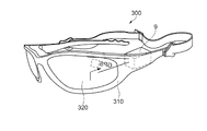
図12は、ヘッドマウントディスプレイ(HMD)の構成を示す概略図である。図12に示すように、ヘッドマウントディスプレイ(HMD)300は、上述の光スキャナー1(1a〜1c)を備えた画像表示装置9を搭載している。ヘッドマウントディスプレイ300は、眼鏡型のフレーム部310を備え、フレーム部310に画像表示装置9が配置されている。そして、画像表示装置9により、フレーム部310の本来レンズである部位に設けられた表示部320に、一方の目で視認される所定の画像を表示する。
FIG. 12 is a schematic diagram illustrating a configuration of a head mounted display (HMD). As shown in FIG. 12, a head mounted display (HMD) 300 is equipped with an image display device 9 including the above-described optical scanner 1 (1a to 1c). The head mounted
表示部320は、透明であってもよく、また、不透明であってもよい。表示部320が透明な場合は、現実世界からの情報に画像表示装置9からの情報を上乗せして使用することができる。なお、ヘッドマウントディスプレイ300に、2つ画像表示装置9を設け、両方の目で視認される画像を、2つの表示部320に表示するようにしてもよい。
The
以上、アクチュエーターとしての光スキャナー及び画像表示装置等の形態について説明したが、これに限定されるものではない。例えば、各部の構成は、同様の機能を有する任意の構成のものに置換することができ、また、他の任意の構成を付加することもできる。また、本発明は、前記各実施形態のうちの、任意の2以上の構成(特徴)を組み合わせたものであってもよい。 The embodiments of the optical scanner as an actuator and the image display device have been described above, but the present invention is not limited to this. For example, the configuration of each unit can be replaced with any configuration having the same function, and any other configuration can be added. Further, the present invention may be a combination of any two or more configurations (features) of the above embodiments.
なお、本発明は上述した実施形態に限定されず、上述した実施形態に種々の変更や改良などを加えることが可能である。変形例を以下に述べる。 Note that the present invention is not limited to the above-described embodiment, and various modifications and improvements can be added to the above-described embodiment. A modification will be described below.
(変形例1)第1及び第2実施形態では、反射板113の第2面113bに、支柱115に接触する円形状のリブ120aを設けたが、この構成に限定されない。図13は、変形例1にかかる反射部の平面図である。図13に示すように、支柱115に接触しないように、第2面113bに円形状(ドーナツ形状)のリブ120dを設けてもよい。このようにしても、上記同様の効果を得ることができる。
(Modification 1) In the first and second embodiments, the
(変形例2)第1及び第2実施形態では、反射板113の半径rの1/2以内の領域から揺動軸(Y軸)に対してθ=45°の角度で反射板113の外周部に向けて延在するリブ120bが設けたが、この構成に限定されない。図14は、変形例2にかかる反射部の平面図である。図14に示すように、反射板113の半径rの1/2以内の領域に配置されたリブ120aと、反射板113の半径rの1/2以内の領域から揺動軸(Y軸)に対してθ=75°の角度で反射板113の外周部に向けて延在するリブ120eとを配置してもよい。このようにしても、上記同様の効果を得ることができる。
(Modification 2) In the first and second embodiments, the outer periphery of the
(変形例3)第3及び第4実施形態では、反射板113の第2面113bに、支柱115に接触しない位置に円弧を含む扇形状のリブ120cを設けたが、この構成に限定されない。図15は、変形例3にかかる反射部の平面図である。図15に示すように、支柱115に接触するように、第2面113bに扇形状のリブ120fを設けてもよい。このようにしても、上記同様の効果を得ることができる。
(Modification 3) In the third and fourth embodiments, the fan-shaped
(変形例4)第1〜第4実施形態では、反射部4,4aには1本の支柱115を配置したが、この構成に限定されない。図16は、変形例4にかかる光スキャナーの構成を示す模式図である。光スキャナー1dは、複数の支柱115aを有してもよい。例えば、図16に示すように、反射板113の中心を避けて設けられた2本の支柱115a,115bを有する反射部4bを構成してもよい。この場合、第1軸となるY軸線(軸部11a,11b)上を除く領域に配置されるように2本の支柱115aを形成する。このようにしても、上記同様の効果を得ることができるとともに、支柱115aと可動板111とを接着剤を用いて接着させるために押圧した際にはみ出す接着剤を軸部11a,11bに付着させることなく、揺動駆動効率を保持させることができる。なお、図9から図12に示すように、画像表示装置9やヘッドマウントディスプレイ300等に反射部4bを有する光スキャナー1dを搭載してもよい。このようにしても、上記同様の効果を得ることができる。
(Modification 4) In the first to fourth embodiments, the
1,1a,1b,1c,1d…アクチュエーターとしての光スキャナー、2…可動部、3…軸部、4,4a,4b…反射部、7…制御部、9…画像表示装置、11a,11b…軸部、12a,12b…第1軸部、13…可動枠、14a,14b…第2軸部、15…外枠支持部、21,21a…永久磁石、31…コイル、32…磁心、40…電圧印加部、91…照射部、100…携帯用画像表示装置、111…可動板、113…反射板、113a…第1面、113b…第2面、114…反射面、115,115a…支柱、120,120a,120b,120c,120d,120e,120f…リブ、210…ヘッドアップディスプレイ、300…ヘッドマウントディスプレイ。
DESCRIPTION OF
Claims (10)
前記可動部を第1軸周りに揺動可能に支持する第1軸部と、
光を反射する反射面を有する反射板、前記反射板の前記反射面と反対側の面に設けられた支柱、を備え、前記可動部に前記支柱が固着された反射部と、を有し、
前記反射板の前記反射面と反対側の面にリブが設けられたことを備えたことを特徴とするアクチュエーター。 Moving parts;
A first shaft portion that supports the movable portion in a swingable manner around a first axis;
A reflection plate having a reflection surface for reflecting light, a support provided on a surface opposite to the reflection surface of the reflection plate, and a reflection portion in which the support is fixed to the movable portion,
An actuator comprising a rib provided on a surface of the reflecting plate opposite to the reflecting surface.
前記リブは、前記支柱を中心とする円形状であることを特徴とするアクチュエーター。 The actuator according to claim 1,
The actuator according to claim 1, wherein the rib has a circular shape centered on the support column.
前記リブは、前記支柱を中心とする円弧を含む扇形状であることを特徴とするアクチュエーター。 The actuator according to claim 1,
The actuator, wherein the rib has a fan shape including an arc centered on the support column.
前記反射板は、平面視において円形状を有し、
前記リブは、前記反射板の前記反射面と反対側の面における前記支柱の中心から前記反射板の半径の1/2以内の領域に設けられたことを特徴とするアクチュエーター。 The actuator according to claim 2 or claim 3,
The reflector has a circular shape in plan view,
The actuator according to claim 1, wherein the rib is provided in a region within a half of a radius of the reflecting plate from a center of the support on a surface opposite to the reflecting surface of the reflecting plate.
前記反射板の半径の1/2以内の領域から前記反射板の外周部に向けて延在するリブをさらに設けたことを特徴とするアクチュエーター。 The actuator according to claim 4, wherein
The actuator further comprising a rib extending from an area within a half of the radius of the reflector toward the outer periphery of the reflector.
前記リブは、前記反射板の板厚方向からの平面視において前記第1軸に対して対称に設けられたことを特徴とするアクチュエーター。 In the actuator according to any one of claims 1 to 5,
The actuator is characterized in that the rib is provided symmetrically with respect to the first axis in a plan view from the thickness direction of the reflector.
前記第1軸部と接続され、かつ、前記可動部を取り囲む枠状の可動枠と、
前記第1軸に交差する第2軸周りに前記可動枠を揺動可能に支持する第2軸部と、を含むことを特徴とするアクチュエーター。 The actuator according to any one of claims 1 to 6,
A frame-like movable frame connected to the first shaft portion and surrounding the movable portion;
An actuator comprising: a second shaft portion that swingably supports the movable frame around a second axis that intersects the first axis.
前記可動部を第1軸周りに揺動可能に支持する第1軸部と、
光を反射する反射面を有する反射板、前記反射板の前記反射面と反対側の面に設けられた支柱、を備え、前記可動部に前記支柱が固着された反射部と、を有し、
前記反射部の前記反射面と反対側の面にリブが設けられたことを備えたことを特徴とする光スキャナー。 Moving parts;
A first shaft portion that supports the movable portion in a swingable manner around a first axis;
A reflection plate having a reflection surface for reflecting light, a support provided on a surface opposite to the reflection surface of the reflection plate, and a reflection portion in which the support is fixed to the movable portion,
An optical scanner comprising a rib provided on a surface of the reflecting portion opposite to the reflecting surface.
前記アクチュエーターに対して光を照射する照射部と、を備えたことを特徴とする画像表示装置。 A movable portion, a first shaft portion that supports the movable portion so as to be swingable about a first axis, a reflecting plate having a reflecting surface that reflects light, and a surface opposite to the reflecting surface of the reflecting plate are provided. An actuator provided with a rib on the surface opposite to the reflecting surface of the reflecting plate, and a reflecting portion having the supporting column fixed to the movable portion.
An image display device comprising: an irradiation unit that irradiates light to the actuator.
前記光スキャナーに対して光を照射する照射部と、を備えたことを特徴とするヘッドマウントディスプレイ。 A movable portion, a first shaft portion that supports the movable portion so as to be swingable about a first axis, a reflecting plate having a reflecting surface that reflects light, and a surface opposite to the reflecting surface of the reflecting plate are provided. An actuator provided with a rib on the surface opposite to the reflecting surface of the reflecting plate, and a reflecting portion having the supporting column fixed to the movable portion.
A head-mounted display, comprising: an irradiation unit that irradiates light to the optical scanner.
Priority Applications (2)
| Application Number | Priority Date | Filing Date | Title |
|---|---|---|---|
| JP2012279066A JP2014123020A (en) | 2012-12-21 | 2012-12-21 | Actuator, optical scanner, image display apparatus and head-mounted display |
| US14/132,495 US20140177020A1 (en) | 2012-12-21 | 2013-12-18 | Actuator, light scanner, image display device, and head mounted display |
Applications Claiming Priority (1)
| Application Number | Priority Date | Filing Date | Title |
|---|---|---|---|
| JP2012279066A JP2014123020A (en) | 2012-12-21 | 2012-12-21 | Actuator, optical scanner, image display apparatus and head-mounted display |
Publications (2)
| Publication Number | Publication Date |
|---|---|
| JP2014123020A true JP2014123020A (en) | 2014-07-03 |
| JP2014123020A5 JP2014123020A5 (en) | 2016-01-28 |
Family
ID=50974326
Family Applications (1)
| Application Number | Title | Priority Date | Filing Date |
|---|---|---|---|
| JP2012279066A Withdrawn JP2014123020A (en) | 2012-12-21 | 2012-12-21 | Actuator, optical scanner, image display apparatus and head-mounted display |
Country Status (2)
| Country | Link |
|---|---|
| US (1) | US20140177020A1 (en) |
| JP (1) | JP2014123020A (en) |
Cited By (7)
| Publication number | Priority date | Publication date | Assignee | Title |
|---|---|---|---|---|
| WO2018109908A1 (en) * | 2016-12-15 | 2018-06-21 | オリンパス株式会社 | Optical deflector |
| JP2018521364A (en) * | 2015-07-06 | 2018-08-02 | トルンプフ シュヴァイツ アクチエンゲゼルシャフトTRUMPF Schweiz AG | Device for deflecting a laser beam |
| JP2018180565A (en) * | 2018-08-09 | 2018-11-15 | 株式会社リコー | Mems mirror, mems scanner, head-up display, and vehicle |
| US10989918B2 (en) | 2016-09-28 | 2021-04-27 | Seiko Epson Corporation | Optical scanner, image display device, head-mounted display, and heads-up display |
| WO2022191046A1 (en) * | 2021-03-12 | 2022-09-15 | 京セラ株式会社 | Mirror actuator |
| WO2022191045A1 (en) * | 2021-03-12 | 2022-09-15 | 京セラ株式会社 | Mirror actuator |
| WO2023162674A1 (en) * | 2022-02-25 | 2023-08-31 | パナソニックIpマネジメント株式会社 | Optical reflective element |
Families Citing this family (3)
| Publication number | Priority date | Publication date | Assignee | Title |
|---|---|---|---|---|
| EP3192770B1 (en) * | 2016-01-12 | 2019-07-17 | TRUMPF Schweiz AG | Device for two-dimensional deflection of a laser beam |
| JP6825612B2 (en) * | 2017-11-13 | 2021-02-03 | 株式会社村田製作所 | MEMS reflector with central support |
| DE102018112809A1 (en) * | 2018-05-29 | 2019-12-05 | Blickfeld GmbH | Actuation of a scanning mirror with an elastic coupling |
Citations (7)
| Publication number | Priority date | Publication date | Assignee | Title |
|---|---|---|---|---|
| JP2002131685A (en) * | 2000-10-25 | 2002-05-09 | Nippon Signal Co Ltd:The | Actuator |
| JP2002365583A (en) * | 2001-06-05 | 2002-12-18 | Fuji Photo Optical Co Ltd | Reflecting mirror for light beam scanner, and manufacturing method therefore |
| JP2009075587A (en) * | 2007-09-21 | 2009-04-09 | Samsung Electronics Co Ltd | Two-axis driving electromagnetic scanner |
| JP2010217648A (en) * | 2009-03-18 | 2010-09-30 | Seiko Epson Corp | Optical device, optical scanner and image forming apparatus |
| JP2011137961A (en) * | 2009-12-28 | 2011-07-14 | Nikon Corp | Spatial light modulator, exposure devices and method of manufacturing them |
| US20110292480A1 (en) * | 2010-05-26 | 2011-12-01 | Wei Ma | Biaxial scanning mirror having resonant frequency adjustment |
| JP2012008357A (en) * | 2010-06-25 | 2012-01-12 | Sony Corp | Mirror structure and its manufacturing method |
Family Cites Families (4)
| Publication number | Priority date | Publication date | Assignee | Title |
|---|---|---|---|---|
| US5579026A (en) * | 1993-05-14 | 1996-11-26 | Olympus Optical Co., Ltd. | Image display apparatus of head mounted type |
| US20050162765A1 (en) * | 2004-01-22 | 2005-07-28 | Hagelin Paul M. | Micromirror with rib reinforcement |
| US8079719B2 (en) * | 2008-03-06 | 2011-12-20 | Microsemi Corporation | Mirror scanning system |
| KR101493367B1 (en) * | 2008-10-02 | 2015-02-13 | 삼성전자 주식회사 | Laser Scanning Unit And Image Forming Apparatus Having The Same |
-
2012
- 2012-12-21 JP JP2012279066A patent/JP2014123020A/en not_active Withdrawn
-
2013
- 2013-12-18 US US14/132,495 patent/US20140177020A1/en not_active Abandoned
Patent Citations (7)
| Publication number | Priority date | Publication date | Assignee | Title |
|---|---|---|---|---|
| JP2002131685A (en) * | 2000-10-25 | 2002-05-09 | Nippon Signal Co Ltd:The | Actuator |
| JP2002365583A (en) * | 2001-06-05 | 2002-12-18 | Fuji Photo Optical Co Ltd | Reflecting mirror for light beam scanner, and manufacturing method therefore |
| JP2009075587A (en) * | 2007-09-21 | 2009-04-09 | Samsung Electronics Co Ltd | Two-axis driving electromagnetic scanner |
| JP2010217648A (en) * | 2009-03-18 | 2010-09-30 | Seiko Epson Corp | Optical device, optical scanner and image forming apparatus |
| JP2011137961A (en) * | 2009-12-28 | 2011-07-14 | Nikon Corp | Spatial light modulator, exposure devices and method of manufacturing them |
| US20110292480A1 (en) * | 2010-05-26 | 2011-12-01 | Wei Ma | Biaxial scanning mirror having resonant frequency adjustment |
| JP2012008357A (en) * | 2010-06-25 | 2012-01-12 | Sony Corp | Mirror structure and its manufacturing method |
Cited By (8)
| Publication number | Priority date | Publication date | Assignee | Title |
|---|---|---|---|---|
| JP2018521364A (en) * | 2015-07-06 | 2018-08-02 | トルンプフ シュヴァイツ アクチエンゲゼルシャフトTRUMPF Schweiz AG | Device for deflecting a laser beam |
| US10989918B2 (en) | 2016-09-28 | 2021-04-27 | Seiko Epson Corporation | Optical scanner, image display device, head-mounted display, and heads-up display |
| WO2018109908A1 (en) * | 2016-12-15 | 2018-06-21 | オリンパス株式会社 | Optical deflector |
| JPWO2018109908A1 (en) * | 2016-12-15 | 2019-10-31 | オリンパス株式会社 | Optical deflector |
| JP2018180565A (en) * | 2018-08-09 | 2018-11-15 | 株式会社リコー | Mems mirror, mems scanner, head-up display, and vehicle |
| WO2022191046A1 (en) * | 2021-03-12 | 2022-09-15 | 京セラ株式会社 | Mirror actuator |
| WO2022191045A1 (en) * | 2021-03-12 | 2022-09-15 | 京セラ株式会社 | Mirror actuator |
| WO2023162674A1 (en) * | 2022-02-25 | 2023-08-31 | パナソニックIpマネジメント株式会社 | Optical reflective element |
Also Published As
| Publication number | Publication date |
|---|---|
| US20140177020A1 (en) | 2014-06-26 |
Similar Documents
| Publication | Publication Date | Title |
|---|---|---|
| JP2014123020A (en) | Actuator, optical scanner, image display apparatus and head-mounted display | |
| JP6056179B2 (en) | Optical scanner and image forming apparatus | |
| JP5983055B2 (en) | Image display device and head mounted display | |
| JP5942576B2 (en) | Optical device, optical scanner, and image display device | |
| JP4232835B2 (en) | Actuator, optical scanner and image forming apparatus | |
| KR20140145074A (en) | Optical device, optical scanner, and image display apparatus | |
| JP5978855B2 (en) | Actuator, optical scanner, image display device, head mounted display | |
| JP6111532B2 (en) | Optical device, optical scanner, and image display device | |
| JP6028400B2 (en) | Image display device and head mounted display | |
| JP2015087444A (en) | Optical scanner, image display device, head-mounted display, and head-up display | |
| JP2013250539A (en) | Image display device and head mounted display | |
| JP6094105B2 (en) | Actuator, optical scanner, image display device, head mounted display | |
| JP2015087442A (en) | Optical scanner, image display device, head-mounted display, and head-up display | |
| JP6233010B2 (en) | Optical scanner, image display device, and head mounted display | |
| JP6107292B2 (en) | Manufacturing method of optical scanner, optical scanner, image display device, and head mounted display | |
| JP6098198B2 (en) | Optical scanner, image display device, head-mounted display, and optical scanner manufacturing method | |
| JP2014021424A (en) | Optical device, image display unit, and method of manufacturing optical device | |
| JP5949345B2 (en) | Actuator, optical scanner, image display device, and head mounted display | |
| JP5978852B2 (en) | Information terminal, portable information terminal and video display system | |
| JP5991001B2 (en) | Optical device, optical scanner, and image display device | |
| JP5713083B2 (en) | Optical device, optical scanner, and image forming apparatus | |
| JP5045611B2 (en) | Actuator, optical scanner and image forming apparatus | |
| JP2014191009A (en) | Actuator, optical scanner, and image display device | |
| JP2014119682A (en) | Optical scanner, image display device and head mount display | |
| JP7035305B2 (en) | Optical scanners, image display devices, head-mounted displays and head-up displays |
Legal Events
| Date | Code | Title | Description |
|---|---|---|---|
| RD04 | Notification of resignation of power of attorney |
Free format text: JAPANESE INTERMEDIATE CODE: A7424 Effective date: 20150109 |
|
| A521 | Request for written amendment filed |
Free format text: JAPANESE INTERMEDIATE CODE: A523 Effective date: 20151203 |
|
| A621 | Written request for application examination |
Free format text: JAPANESE INTERMEDIATE CODE: A621 Effective date: 20151203 |
|
| RD04 | Notification of resignation of power of attorney |
Free format text: JAPANESE INTERMEDIATE CODE: A7424 Effective date: 20160609 |
|
| RD03 | Notification of appointment of power of attorney |
Free format text: JAPANESE INTERMEDIATE CODE: A7423 Effective date: 20160621 |
|
| A977 | Report on retrieval |
Free format text: JAPANESE INTERMEDIATE CODE: A971007 Effective date: 20160921 |
|
| A131 | Notification of reasons for refusal |
Free format text: JAPANESE INTERMEDIATE CODE: A131 Effective date: 20160927 |
|
| A761 | Written withdrawal of application |
Free format text: JAPANESE INTERMEDIATE CODE: A761 Effective date: 20161122 |