JP2014090664A - Battery control system and electric cell - Google Patents
Battery control system and electric cell Download PDFInfo
- Publication number
- JP2014090664A JP2014090664A JP2014003149A JP2014003149A JP2014090664A JP 2014090664 A JP2014090664 A JP 2014090664A JP 2014003149 A JP2014003149 A JP 2014003149A JP 2014003149 A JP2014003149 A JP 2014003149A JP 2014090664 A JP2014090664 A JP 2014090664A
- Authority
- JP
- Japan
- Prior art keywords
- battery
- voltage
- communication
- rank
- circuit
- Prior art date
- Legal status (The legal status is an assumption and is not a legal conclusion. Google has not performed a legal analysis and makes no representation as to the accuracy of the status listed.)
- Pending
Links
Images


Classifications
-
- H—ELECTRICITY
- H01—ELECTRIC ELEMENTS
- H01M—PROCESSES OR MEANS, e.g. BATTERIES, FOR THE DIRECT CONVERSION OF CHEMICAL ENERGY INTO ELECTRICAL ENERGY
- H01M10/00—Secondary cells; Manufacture thereof
- H01M10/42—Methods or arrangements for servicing or maintenance of secondary cells or secondary half-cells
- H01M10/4207—Methods or arrangements for servicing or maintenance of secondary cells or secondary half-cells for several batteries or cells simultaneously or sequentially
-
- H—ELECTRICITY
- H01—ELECTRIC ELEMENTS
- H01M—PROCESSES OR MEANS, e.g. BATTERIES, FOR THE DIRECT CONVERSION OF CHEMICAL ENERGY INTO ELECTRICAL ENERGY
- H01M10/00—Secondary cells; Manufacture thereof
- H01M10/42—Methods or arrangements for servicing or maintenance of secondary cells or secondary half-cells
- H01M10/44—Methods for charging or discharging
-
- H—ELECTRICITY
- H01—ELECTRIC ELEMENTS
- H01M—PROCESSES OR MEANS, e.g. BATTERIES, FOR THE DIRECT CONVERSION OF CHEMICAL ENERGY INTO ELECTRICAL ENERGY
- H01M10/00—Secondary cells; Manufacture thereof
- H01M10/42—Methods or arrangements for servicing or maintenance of secondary cells or secondary half-cells
- H01M10/48—Accumulators combined with arrangements for measuring, testing or indicating the condition of cells, e.g. the level or density of the electrolyte
- H01M10/482—Accumulators combined with arrangements for measuring, testing or indicating the condition of cells, e.g. the level or density of the electrolyte for several batteries or cells simultaneously or sequentially
-
- H—ELECTRICITY
- H02—GENERATION; CONVERSION OR DISTRIBUTION OF ELECTRIC POWER
- H02J—CIRCUIT ARRANGEMENTS OR SYSTEMS FOR SUPPLYING OR DISTRIBUTING ELECTRIC POWER; SYSTEMS FOR STORING ELECTRIC ENERGY
- H02J7/00—Circuit arrangements for charging or depolarising batteries or for supplying loads from batteries
- H02J7/00032—Circuit arrangements for charging or depolarising batteries or for supplying loads from batteries characterised by data exchange
- H02J7/00036—Charger exchanging data with battery
-
- H—ELECTRICITY
- H02—GENERATION; CONVERSION OR DISTRIBUTION OF ELECTRIC POWER
- H02J—CIRCUIT ARRANGEMENTS OR SYSTEMS FOR SUPPLYING OR DISTRIBUTING ELECTRIC POWER; SYSTEMS FOR STORING ELECTRIC ENERGY
- H02J7/00—Circuit arrangements for charging or depolarising batteries or for supplying loads from batteries
- H02J7/0063—Circuit arrangements for charging or depolarising batteries or for supplying loads from batteries with circuits adapted for supplying loads from the battery
-
- H—ELECTRICITY
- H02—GENERATION; CONVERSION OR DISTRIBUTION OF ELECTRIC POWER
- H02J—CIRCUIT ARRANGEMENTS OR SYSTEMS FOR SUPPLYING OR DISTRIBUTING ELECTRIC POWER; SYSTEMS FOR STORING ELECTRIC ENERGY
- H02J7/00—Circuit arrangements for charging or depolarising batteries or for supplying loads from batteries
- H02J7/007—Regulation of charging or discharging current or voltage
- H02J7/00712—Regulation of charging or discharging current or voltage the cycle being controlled or terminated in response to electric parameters
- H02J7/007182—Regulation of charging or discharging current or voltage the cycle being controlled or terminated in response to electric parameters in response to battery voltage
-
- H—ELECTRICITY
- H02—GENERATION; CONVERSION OR DISTRIBUTION OF ELECTRIC POWER
- H02J—CIRCUIT ARRANGEMENTS OR SYSTEMS FOR SUPPLYING OR DISTRIBUTING ELECTRIC POWER; SYSTEMS FOR STORING ELECTRIC ENERGY
- H02J7/00—Circuit arrangements for charging or depolarising batteries or for supplying loads from batteries
- H02J7/007—Regulation of charging or discharging current or voltage
- H02J7/007188—Regulation of charging or discharging current or voltage the charge cycle being controlled or terminated in response to non-electric parameters
- H02J7/007192—Regulation of charging or discharging current or voltage the charge cycle being controlled or terminated in response to non-electric parameters in response to temperature
- H02J7/007194—Regulation of charging or discharging current or voltage the charge cycle being controlled or terminated in response to non-electric parameters in response to temperature of the battery
-
- H—ELECTRICITY
- H02—GENERATION; CONVERSION OR DISTRIBUTION OF ELECTRIC POWER
- H02J—CIRCUIT ARRANGEMENTS OR SYSTEMS FOR SUPPLYING OR DISTRIBUTING ELECTRIC POWER; SYSTEMS FOR STORING ELECTRIC ENERGY
- H02J7/00—Circuit arrangements for charging or depolarising batteries or for supplying loads from batteries
- H02J7/02—Circuit arrangements for charging or depolarising batteries or for supplying loads from batteries for charging batteries from ac mains by converters
-
- Y—GENERAL TAGGING OF NEW TECHNOLOGICAL DEVELOPMENTS; GENERAL TAGGING OF CROSS-SECTIONAL TECHNOLOGIES SPANNING OVER SEVERAL SECTIONS OF THE IPC; TECHNICAL SUBJECTS COVERED BY FORMER USPC CROSS-REFERENCE ART COLLECTIONS [XRACs] AND DIGESTS
- Y02—TECHNOLOGIES OR APPLICATIONS FOR MITIGATION OR ADAPTATION AGAINST CLIMATE CHANGE
- Y02E—REDUCTION OF GREENHOUSE GAS [GHG] EMISSIONS, RELATED TO ENERGY GENERATION, TRANSMISSION OR DISTRIBUTION
- Y02E60/00—Enabling technologies; Technologies with a potential or indirect contribution to GHG emissions mitigation
- Y02E60/10—Energy storage using batteries
Landscapes
- Engineering & Computer Science (AREA)
- Power Engineering (AREA)
- Manufacturing & Machinery (AREA)
- Chemical & Material Sciences (AREA)
- Chemical Kinetics & Catalysis (AREA)
- Electrochemistry (AREA)
- General Chemical & Material Sciences (AREA)
- Charge And Discharge Circuits For Batteries Or The Like (AREA)
- Secondary Cells (AREA)
- Sealing Battery Cases Or Jackets (AREA)
- Battery Mounting, Suspending (AREA)
Abstract
Description
本発明は、組電池用単電池、電池制御システムおよび電池制御方法に関し、特には、電池の電圧を調節可能な組電池用単電池、電池制御システムおよび電池制御方法に関する。 The present invention relates to an assembled battery cell, a battery control system, and a battery control method, and more particularly, to an assembled battery cell, a battery control system, and a battery control method capable of adjusting the battery voltage.
二次電池セルを相互に接続してなる組電池の電圧を調節する電池制御システムが知られている。 A battery control system that adjusts the voltage of an assembled battery formed by interconnecting secondary battery cells is known.
特許文献1(特表平11−509669号公報)には、各電池セルの電圧を制御するための情報(電池セルの電圧等)を無線または有線で伝達するエネルギ管理システムが記載されている。 Japanese Patent Application Laid-Open No. 11-509669 discloses an energy management system that transmits information for controlling the voltage of each battery cell (such as the voltage of the battery cell) wirelessly or by wire.
このエネルギ管理システムでは、数個の電池が直列に接続された電池集合体を一つの制御単位とし、その単位ごとに、一つの電池制御モジュールが搭載されている。 In this energy management system, a battery assembly in which several batteries are connected in series is defined as one control unit, and one battery control module is mounted for each unit.
このエネルギ管理システムは、電池集合体全体の電圧などの作動パラメータの測定、あるいは作動パラメータの制御を行う。 This energy management system measures the operating parameters such as the voltage of the entire battery assembly or controls the operating parameters.
このエネルギ管理システムでは、一つの制御装置が、複数の制御単位内の複数の電池制御モジュールからの情報を集中管理する。また、この制御装置が、複数の電池制御モジュールへ指令を伝達する。使用できる電池の例としては、ニッケルカドミウム電池などの他、リチウムポリマー電池が記載されている。 In this energy management system, one control device centrally manages information from a plurality of battery control modules in a plurality of control units. Moreover, this control apparatus transmits a command to a plurality of battery control modules. Examples of batteries that can be used include lithium polymer batteries as well as nickel cadmium batteries.
制御装置は、各電池制御モジュールから無線で送信された検出結果を受信する。制御装置は、その検出結果に基づいて、個々の電池セルの電圧を均等にするための制御信号を生成する。制御装置は、その制御信号を無線で各電池制御モジュールに送信する。 The control device receives the detection result transmitted wirelessly from each battery control module. The control device generates a control signal for equalizing the voltages of the individual battery cells based on the detection result. The control device transmits the control signal to each battery control module wirelessly.
各電池制御モジュールは、その制御信号を受信すると、その制御信号に基づいて電池セルの電圧を放電する。よって、個々の電池セルの電圧を均等にすることが可能になる。 Each battery control module, when receiving the control signal, discharges the voltage of the battery cell based on the control signal. Therefore, it becomes possible to make the voltage of each battery cell equal.
特許文献1に記載されたエネルギ管理システムでは、1つの制御装置が、組電池全体を制御する。このため、組電池用単電池のそれぞれは、その制御装置に対応する構成を有する必要がある。よって、例えば、組電池用単電池の直列数が変更されると、制御装置の仕様も変更しなければならない。したがって、組電池の設計変更の自由度、複数仕様の組電池を製造する上での利便性、ユーザー側での使いやすさに制限があった。
In the energy management system described in
また、特許文献1に記載されたエネルギ管理システムでは、制御装置が各々の電池制御モジュールと無線で情報を通信するため、以下の問題が生じる。
Moreover, in the energy management system described in
制御装置と各電池制御モジュールとの無線通信では、通信距離が長くなるほど、通信情報にノイズがのりやすくなる。よって、制御装置が、最も遠く離れた電池制御モジュールと情報を通信する際、その情報がノイズの影響を受けやすくなる。情報がノイズの影響を受けると、制御装置は、各電池セルの電圧を的確に制御できなくなる。 In the wireless communication between the control device and each battery control module, the longer the communication distance, the easier it is for noise to appear in the communication information. Therefore, when the control device communicates information with the battery control module farthest away, the information is easily affected by noise. If the information is affected by noise, the control device cannot accurately control the voltage of each battery cell.
また、制御装置が各電池制御モジュールと有線で情報を通信する場合、電池制御モジュールと制御装置とを接続する通信線が、電池制御モジュールごとに必要となり、構成が大きくなってしまう。 In addition, when the control device communicates information with each battery control module in a wired manner, a communication line that connects the battery control module and the control device is required for each battery control module, and the configuration becomes large.
また、制御装置が各電池制御モジュールと情報をやり取りするため、制御装置の負荷が大きくなってしまう。 In addition, since the control device exchanges information with each battery control module, the load on the control device increases.
本発明の目的は、上述した課題を解決することが可能な組電池用単電池、電池制御システムおよび電池制御方法を提供することである。 The objective of this invention is providing the cell for assembled batteries, a battery control system, and a battery control method which can solve the subject mentioned above.
本発明の電池制御システムは、
複数の単電池と、前記複数の単電池各々に対応する通信装置と、を含む電池制御システムであって
前記単電池のうち少なくとも1つに異常が発生した場合に、異常が発生した単電池および他の単電池を強制的に放電させる。また、
本発明の電池制御システムは、
複数の単電池を制御する電池制御システムであって、
単電池のうち少なくとも1つに異常が発生した場合に、異常が発生した単電池および他の単電池を強制的に放電させる。また、
本発明の単電池は、
他の単電池と相互接続可能な単電池であって、
二次電池と、
前記二次電池の状態を測定する測定手段と、
他の単電池と通信する通信手段と、
前記二次電池を放電させる放電手段とを有し、
前記測定手段による測定によって前記二次電池の異常が検出された場合に、前記放電手段は前記二次電池を放電させ、かつ、前記通信手段は、他の単電池に放電を指示する信号を送る。また、
本発明の単電池は、
他の単電池と相互接続可能な単電池であって、
二次電池と、
他の単電池と通信する通信手段と、
前記二次電池を放電させる放電手段とを有し、
前記通信手段が他の単電池から放電を指示する信号を受信した場合に、前記放電手段により前記二次電池を放電させ、更に前記通信手段から少なくとも一つの別の他の単電池に放電を指示する信号を送る。
The battery control system of the present invention includes:
A battery control system including a plurality of unit cells and a communication device corresponding to each of the plurality of unit cells, and when a failure occurs in at least one of the unit cells, Force other cells to discharge. Also,
The battery control system of the present invention includes:
A battery control system for controlling a plurality of single cells,
When an abnormality occurs in at least one of the unit cells, the unit cell in which the abnormality has occurred and other unit cells are forcibly discharged. Also,
The cell of the present invention is
A cell that can be interconnected with other cells,
A secondary battery,
Measuring means for measuring the state of the secondary battery;
Communication means for communicating with other cells,
Discharging means for discharging the secondary battery,
When the abnormality of the secondary battery is detected by the measurement by the measuring means, the discharging means discharges the secondary battery, and the communication means sends a signal instructing other unit cells to discharge. . Also,
The cell of the present invention is
A cell that can be interconnected with other cells,
A secondary battery,
Communication means for communicating with other cells,
Discharging means for discharging the secondary battery,
When the communication means receives a signal instructing discharge from another unit cell, the discharge unit causes the secondary battery to discharge, and further, the communication unit instructs at least one other unit cell to discharge. Send a signal to
本発明によれば、組電池の中の個々の単電池の電圧を集中管理して制御する装置が不要となり、組電池の設計変更の自由度、複数仕様の組電池を製造する上での利便性、ユーザー側での使いやすさを向上することが可能になり、また、電池制御システムにおいて、ノイズの影響を受け難く、構成の大型化を防ぎ、管理装置の負荷を小さくすることが可能になる。 According to the present invention, an apparatus for centrally managing and controlling the voltages of individual cells in an assembled battery is not required, the degree of freedom in changing the design of the assembled battery, and the convenience in manufacturing an assembled battery with multiple specifications. In addition, the battery control system is less susceptible to noise in the battery control system, prevents the configuration from becoming large, and reduces the load on the management device. Become.
以下、本発明の実施形態を図面を参照して説明する。 Hereinafter, embodiments of the present invention will be described with reference to the drawings.
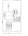
図1は、本発明の第1実施形態の電池制御システムを示したブロック図である。 FIG. 1 is a block diagram showing a battery control system according to a first embodiment of the present invention.
図1において、電池制御システムは、3台以上のスレーブ装置(本実施形態では、スレーブ装置1ないし3)と、マスタ装置4と、を含む。
In FIG. 1, the battery control system includes three or more slave devices (
複数のスレーブ装置1ないし3は、通信装置の一例である。複数のスレーブ装置1ないし3は、1チップで構成され、予め順位付けされている。スレーブ装置1ないし3、および、マスタ装置4は、順位を、各スレーブ装置の識別子としても用いる。本実施形態では、スレーブ装置1には、順位「1」が付されており、スレーブ装置2には、順位「2」が付されており、スレーブ装置3には、順位「3」が付されている。なお、本実施形態では、順位は、値が小さいほど上位になるとする。
The plurality of
スレーブ装置1は、最高順位「1」を有し、電池5と対応し、電池5に関する情報を検出する。また、スレーブ装置1は、スレーブ装置2と、マスタ装置4と、有線または無線で通信する。
The
スレーブ装置1と電池5とで、単電池が構成される。スレーブ装置1は、制御回路の一例である。電池5は、単位セルの一例である。
The
スレーブ装置2は、電池6と対応し、電池6に関する情報を検出する。また、スレーブ装置2は、スレーブ装置1および3と、マスタ装置4と、有線または無電で通信する。
The
スレーブ装置2と電池6とで、単電池が構成される。スレーブ装置2は、制御回路の一例である。電池6は、単位セルの一例である。
The
スレーブ装置3は、最低順位「3」を有し、電池7と対応し、電池7に関する情報を検出する。また、スレーブ装置3は、スレーブ装置2と、マスタ装置4と、有線または無線で通信する。
The
スレーブ装置3と電池7とで、単電池が構成される。スレーブ装置3は、制御回路の一例である。電池7は、単位セルの一例である。
The
マスタ装置4は、最高順位のスレーブ装置、具体的には、スレーブ装置1に動作信号を送信する。
The
電池5ないし7は、例えば、リチウムイオン2次電池セルである。電池5ないし7は、直列に接続されている。なお、電池5ないし7は、並列に接続されていてもよい。また、最高順位のスレーブ装置1は、最高順位の次の順位のスレーブ装置2と隣接している。最低順位のスレーブ装置3は、最低順位の直前の順位のスレーブ装置2と隣接している。スレーブ装置2は、スレーブ装置2の順位の直前および直後の順位のスレーブ装置1および3と隣接している。
The
図2は、スレーブ装置1の一例を示したブロック図である。なお、図2において、図1に示したものと同一のものには同一符号を付してある。
FIG. 2 is a block diagram illustrating an example of the
図2において、スレーブ装置1は、最高順位の通信装置の一例である。スレーブ装置1は、セル電圧検出回路1a、電流検出回路1b、セル温度検出回路1c、イコライズ回路1d、情報記憶回路1e、通信回路1f、CPU1g、および、電源回路1hを含む。情報記憶回路1eは、順位記憶部1e1、第1送信先記憶部1e2、電圧記憶部1e3、および、目標電圧記憶部1e4、を含む。
In FIG. 2, the
セル電圧検出回路1aは、一般的に第1検出手段および測定手段と呼ぶことができる。
Cell
セル電圧検出回路1aは、第1検出部および測定部の一例である。セル電圧検出回路1aは、電池5の電圧を検出し、その電圧値(電池情報情報)をCPU1gに提供する。電流検出回路1bは、電池5から流れる電流を検出し、その電流値をCPU1gに提供する。
The cell
セル温度検出回路1cは、一般的に測定手段と呼ぶことができる。 Cell temperature detection circuit 1c can be generally referred to as measurement means.
セル温度検出回路1cは、電池5の温度を検出し、その温度(電池状態情報)をCPU1gに提供する。
The cell temperature detection circuit 1c detects the temperature of the
イコライズ回路1dは、一般的に第1調節手段および放電手段と呼ぶことができる。 Equalize circuit 1d can be generally referred to as first adjusting means and discharging means.
イコライズ回路1dは、第1調節部および放電部の一例である。イコライズ回路1dは、電池5の電圧を調節する。例えば、イコライズ回路1dは、スイッチを有する抵抗素子であり、スイッチがオンすると、電池5からの電流を抵抗素子に流して、電池5の電圧を低下させる。
The equalize circuit 1d is an example of a first adjustment unit and a discharge unit. The equalizing circuit 1 d adjusts the voltage of the
情報記憶回路1eは、種々の情報を記憶する。 The information storage circuit 1e stores various information.
順位記憶部1e1は、スレーブ装置1に付与された順位「1」(最高順位)を記憶する。
The rank storage unit 1
第1送信先記憶部1e2は、情報の送信先に関する情報を記憶する。具体的には、第1送信先記憶部1e2には、最高順位「1」の次の順位である「2」が記憶されている。なお、順位「2」は、スレーブ装置2に付与されている。つまり、第1送信先記憶部1e2には、送信先として、スレーブ装置2の識別子が記憶されている。
The first transmission destination storage unit 1e2 stores information related to the transmission destination of information. Specifically, “2”, which is the next rank after the highest rank “1”, is stored in the first transmission destination storage unit 1e2. The rank “2” is assigned to the
電圧記憶部1e3は、セル電圧検出回路1aが検出した電圧値を記憶する。
The voltage storage unit 1e3 stores the voltage value detected by the cell
目標電圧記憶部1e4は、目標とする電圧値を記憶する。具体的には、目標電圧記憶部1e4には、電池5ないし7の電圧値の中で最も低い電圧値が記憶される。
The target voltage storage unit 1e4 stores a target voltage value. Specifically, the target voltage storage unit 1e4 stores the lowest voltage value among the voltage values of the
通信回路1fは、一般的に第1通信手段、送信手段および受信手段と呼ぶことができる。
通信回路1fは、第1通信部、送信部および受信部の一例である。通信回路1fは、マスタ装置4と、第1送信先記憶部1e2に記憶された送信先と通信する。
The
CPU1gは、一般的に第1制御手段と呼ぶことができる。 CPU 1g can be generally referred to as first control means.
CPU1gは、第1制御部の一例である。CPU1gは、スレーブ装置1の動作を制御する。CPU1gは、例えば、以下のような制御を実行する。
The CPU 1g is an example of a first control unit. The CPU 1g controls the operation of the
CPU1gは、通信回路1fがマスタ装置4から動作信号を受け付けた場合に、セル電圧検出回路1aが検出した電圧値を、通信回路1fから、第1送信先記憶部1e2に送信先として記憶されているスレーブ装置2に送信する。
When the
CPU1gは、通信回路1fが、スレーブ装置2から電圧値を受け付けた場合に、電池5の電圧をその受け付けられた電圧値に調節する動作を、イコライズ回路1dに実行させる。具体的には、CPU1gは、その受け付けられた電圧値を目標電圧記憶部1e4に記憶し、その後、イコライズ回路1dに、電池5の電圧を、目標電圧記憶部1e4に記憶された電圧値に調節する動作を実行させる。
When the
また、CPU1gは、セル電圧検出回路1aが検出した電圧と、スレーブ装置1の順位「1」(スレーブ装置1の識別子)と、をマスタ装置4に送信する処理を、通信回路1fに実行させる。CPU1gは、電流検出回路1bが検出した電流と順位「1」をマスタ装置4に送信する処理を、通信回路1fに実行させる。CPU1gは、セル温度検出回路1cが検出した温度と順位「1」をマスタ装置4に送信する処理を、通信回路1fに実行させる。
Further, the CPU 1g causes the
CPU1gは、相互接続された単電池の電圧が近づくように、電池状態情報(電池5の電圧)と外部情報(他の単電池からの情報)の両方の情報に基づいて、イコライズ回路1dを用いて電池5を放電させる。
The CPU 1g uses the equalize circuit 1d based on both the battery state information (voltage of the battery 5) and external information (information from other single cells) so that the voltages of the interconnected single cells approach each other. The
電源回路1hは、スレーブ装置1内の各回路に電源を供給する。
The power supply circuit 1 h supplies power to each circuit in the
図3は、スレーブ装置3の一例を示したブロック図である。なお、図3において、図1に示したものと同一のものには同一符号を付してある。
FIG. 3 is a block diagram illustrating an example of the
図3において、スレーブ装置3は、最低順位の通信装置の一例である。スレーブ装置3は、セル電圧検出回路3a、電流検出回路3b、セル温度検出回路3c、イコライズ回路3d、情報記憶回路3e、通信回路3f、CPU3g、および、電源回路3hを含む。情報記憶回路3eは、順位記憶部3e1、第1送信先記憶部3e2、電圧記憶部3e3、および、目標電圧記憶部3e4と、を含む。
In FIG. 3, the
セル電圧検出回路3aは、一般的に第2検出手段および測定手段と呼ぶことができる。 Cell voltage detection circuit 3a can be generally referred to as second detection means and measurement means.
セル電圧検出回路3aは、第2検出部および測定部の一例である。セル電圧検出回路3aは、電池7の電圧値を検出し、その電圧値(電池情報情報)をCPU3gに提供する。電流検出回路3bは、電池7から流れる電流を検出し、その電流値をCPU3gに提供する。
The cell voltage detection circuit 3a is an example of a second detection unit and a measurement unit. The cell voltage detection circuit 3a detects the voltage value of the battery 7 and provides the voltage value (battery information information) to the CPU 3g. The
セル温度検出回路3cは、一般的に測定手段と呼ぶことができる。
Cell
セル温度検出回路3cは、電池7の温度を検出し、その温度(電池状態情報)をCPU3gに提供する。
The cell
イコライズ回路3dは、一般的に第2調節手段および放電手段と呼ぶことができる。
Equalize
イコライズ回路3dは、第2調節部および放電部の一例である。イコライズ回路3dは、電池7の電圧を調節する。例えば、イコライズ回路3dは、スイッチを有する抵抗素子であり、スイッチがオンすると、電池7からの電流を抵抗素子に流して、電池7の電圧を低下させる。
The equalize
情報記憶回路3eは、種々の情報を記憶する。
The
順位記憶部3e1は、スレーブ装置3に付与された順位「3」(最低順位)を記憶する。
The
第1送信先記憶部3e2は、情報の送信先に関する情報を記憶する。具体的には、第1送信先記憶部3e2には、最低順位「3」の直前の順位である「2」が記憶されている。なお、順位「2」は、スレーブ装置2に付与されている。つまり、第1送信先記憶部3e2には、送信先として、スレーブ装置2の識別子が記憶されている。
The first transmission destination storage unit 3e2 stores information related to the transmission destination of information. Specifically, the first transmission destination storage unit 3e2 stores “2”, which is the rank immediately before the lowest rank “3”. The rank “2” is assigned to the
電圧記憶部3e3は、セル電圧検出回路3aが検出した電池7の電圧値を記憶する。 The voltage storage unit 3e3 stores the voltage value of the battery 7 detected by the cell voltage detection circuit 3a.
目標電圧記憶部3e4は、目標とする電圧値を記憶する。具体的には、目標電圧記憶部3e4には、電池5ないし7の電圧値の中で最も低い電圧値が記憶される。
The target voltage storage unit 3e4 stores a target voltage value. Specifically, the target voltage storage unit 3e4 stores the lowest voltage value among the voltage values of the
通信回路3fは、一般的に第2通信手段、送信手段および受信手段と呼ぶことができる。
通信回路3fは、第2通信部、送信部および受信部の一例である。通信回路3fは、CPU3gによって制御され、第1送信先記憶部3e2に記憶された送信先、および、マスタ装置4と通信する。
The
CPU3gは、一般的に第2制御手段と呼ぶことができる。 CPU 3g can be generally referred to as second control means.
CPU3gは、第2制御部の一例である。CPU3gは、スレーブ装置3の動作を制御する。CPU3gは、例えば、以下のような制御を実行する。
The CPU 3g is an example of a second control unit. The CPU 3g controls the operation of the
CPU3gは、通信回路3fが、第1送信先記憶部3e2に送信先として記憶されているスレーブ装置2から電圧値を受け付けた場合、その受け付けた電圧値と、セル電圧検出回路3aが検出した電圧値のうち、低い方の電圧値を選択する。
When the
CPU3gは、その選択された電圧値を、通信回路3fから、第1送信先記憶部3e2に送信先として記憶されているスレーブ装置2に送信する。
The CPU 3g transmits the selected voltage value from the
CPU3gは、電池7の電圧をその選択された電圧値に調節する動作を、イコライズ回路3dに実行させる。具体的には、CPU3gは、その選択された電圧値を目標電圧記憶部3e4に記憶し、その後、イコライズ回路3dに、電池7の電圧を、目標電圧記憶部3e4に記憶された電圧値に調節する動作を実行させる。
The CPU 3g causes the equalizing
また、CPU3gは、セル電圧検出回路3aが検出した電圧と、スレーブ装置3の順位「3」(スレーブ装置3の識別子)と、をマスタ装置4に送信する処理を、通信回路3fに実行させる。CPU3gは、電流検出回路3bが検出した電流と順位「3」をマスタ装置4に送信する処理を、通信回路3fに実行させる。CPU3gは、セル温度検出回路3cが検出した温度と順位「3」をマスタ装置4に送信する処理を、通信回路3fに実行させる。
Further, the CPU 3g causes the
CPU3gは、相互接続された単電池の電圧が近づくように、電池状態情報(電池7の電圧)と外部情報(他の単電池からの情報)の両方の情報に基づいて、イコライズ回路3dを用いて電池7を放電させる。
The CPU 3g uses the equalize
電源回路3hは、スレーブ装置3内の各回路に電源を供給する。
The
図4は、スレーブ装置2の一例を示したブロック図である。なお、図4において、図1に示したものと同一のものには同一符号を付してある。
FIG. 4 is a block diagram illustrating an example of the
図4において、スレーブ装置2は、他の通信装置の一例である。スレーブ装置2は、セル電圧検出回路2a、電流検出回路2b、セル温度検出回路2c、イコライズ回路2d、情報記憶回路2e、通信回路2f、CPU2g、および、電源回路2hを含む。情報記憶回路2eは、順位記憶部2e1、第1送信先記憶部2e2、第2送信先記憶部2e3、電圧記憶部2e4、および、目標電圧記憶部2e5を含む。
In FIG. 4, the
セル電圧検出回路2aは、一般的に第3検出手段および測定手段と呼ぶことができる。 Cell voltage detection circuit 2a can be generally referred to as third detection means and measurement means.
セル電圧検出回路2aは、第3検出部および測定部の一例である。セル電圧検出回路2aは、電池6の電圧を検出し、その電圧値(電池情報情報)をCPU2gに提供する。電流検出回路2bは、電池6から流れる電流を検出し、その電流値をCPU2gに提供する。
The cell voltage detection circuit 2a is an example of a third detection unit and a measurement unit. The cell voltage detection circuit 2a detects the voltage of the
セル温度検出回路2cは、一般的に測定手段と呼ぶことができる。
Cell
セル温度検出回路2cは、電池6の温度を検出し、その温度(電池状態情報)をCPU2gに提供する。
The cell
イコライズ回路2dは、一般的に第3調節手段および放電手段と呼ぶことができる。
Equalize
イコライズ回路2dは、第3調節部および放電部の一例である。イコライズ回路2dは、電池6の電圧を調節する。例えば、イコライズ回路2dは、スイッチを有する抵抗素子であり、スイッチがオンすると、電池6からの電流を抵抗素子に流して、電池6の電圧を低下させる。
The equalize
情報記憶回路2eは、種々の情報を記憶する。 The information storage circuit 2e stores various information.
順位記憶部2e1は、スレーブ装置2に付与された順位「2」を記憶する。
The rank storage unit 2
第1送信先記憶部2e2は、情報の送信先に関する情報を記憶する。具体的には、第1送信先記憶部2e2には、順位「2」の直後の順位「3」が記憶されている。なお、順位「3」は、スレーブ装置3に付与されている。つまり、第1送信先記憶部2e2には、送信先として、スレーブ装置3の識別子が記憶されている。
The first transmission destination storage unit 2e2 stores information related to the transmission destination of information. Specifically, the rank “3” immediately after the rank “2” is stored in the first transmission destination storage unit 2e2. The rank “3” is assigned to the
第2送信先記憶部2e3は、情報の送信先に関する情報を記憶する。具体的には、第2送信先記憶部2e3には、順位「2」の直前の順位「1」が記憶されている。なお、順位「1」は、スレーブ装置1に付与されている。つまり、第2送信先記憶部2e3には、送信先として、スレーブ装置1の識別子が記憶されている。
The second transmission destination storage unit 2e3 stores information related to the transmission destination of information. Specifically, the second transmission destination storage unit 2e3 stores the rank “1” immediately before the rank “2”. The rank “1” is assigned to the
電圧記憶部2e4は、セル電圧検出回路2aが検出した電池6の電圧値を記憶する。
The voltage storage unit 2e4 stores the voltage value of the
目標電圧記憶部2e5は、目標とする電圧値を記憶する。具体的には、目標電圧記憶部2e5には、電池5ないし7の電圧値の中で最も低い電圧値が記憶される。
The target voltage storage unit 2e5 stores a target voltage value. Specifically, the target voltage storage unit 2e5 stores the lowest voltage value among the voltage values of the
通信回路2fは、一般的に第3通信手段、送信手段および受信手段と呼ぶことができる。 Communication circuit 2f can be generally referred to as third communication means, transmission means, and reception means.
通信回路2fは、第3通信部、送信部および受信部の一例である。通信回路2fは、第1送信先記憶部2e2に記憶された送信先、第2送信先記憶部2e3に記憶された送信先、および、マスタ装置4と通信する。
The communication circuit 2f is an example of a third communication unit, a transmission unit, and a reception unit. The communication circuit 2f communicates with the transmission destination stored in the first transmission destination storage unit 2e2, the transmission destination stored in the second transmission destination storage unit 2e3, and the
CPU2gは、一般的に第3制御手段と呼ぶことができる。 CPU 2g can generally be referred to as third control means.
CPU2gは、第3制御部の一例である。CPU2gは、スレーブ装置2の動作を制御する。
The CPU 2g is an example of a third control unit. The CPU 2g controls the operation of the
CPU2gは、例えば、以下のような制御を実行する。 For example, the CPU 2g executes the following control.
CPU2gは、通信回路2fが、第2送信先記憶部2e3に送信先として記憶されているスレーブ装置1から電圧値を受け付けた場合、スレーブ装置1からの電圧値と、セル電圧検出回路2aが検出した電圧値のうち、低い方の電圧値を選択する。その後、CPU2gは、その選択された電圧値を、通信回路2fから、第1送信先記憶部2e2に送信先として記憶されているスレーブ装置3に送信する。
When the communication circuit 2f receives the voltage value from the
CPU2gは、通信回路2fが、第1送信先記憶部2e2に送信先として記憶されているスレーブ装置3から電圧値を受け付けた場合、スレーブ装置3からの電圧値を、通信回路2fから、第2送信先記憶部2e3に送信先として記憶されているスレーブ装置1に送信する。
When the communication circuit 2f receives the voltage value from the
その後、CPU2gは、電池6の電圧をスレーブ装置1に送信した電圧値に調節する動作を、イコライズ回路2dに実行させる。具体的には、CPU2gは、スレーブ装置1に送信した電圧値を目標電圧記憶部2e5に記憶し、その後、イコライズ回路2dに、電池6の電圧を、目標電圧記憶部2e5に記憶された電圧値に調節する動作を実行させる。
Thereafter, the CPU 2g causes the equalize
また、CPU2gは、セル電圧検出回路2aが検出した電圧と、スレーブ装置2の順位「2」(スレーブ装置2の識別子)と、をマスタ装置4に送信する処理を、通信回路2fに実行させる。CPU2gは、電流検出回路2bが検出した電流と順位「2」をマスタ装置4に送信する処理を、通信回路2fに実行させる。CPU2gは、セル温度検出回路2cが検出した温度と順位「2」をマスタ装置4に送信する処理を、通信回路2fに実行させる。
In addition, the CPU 2g causes the communication circuit 2f to execute a process of transmitting the voltage detected by the cell voltage detection circuit 2a and the rank “2” of the slave device 2 (identifier of the slave device 2) to the
CPU2gは、相互接続された単電池の電圧が近づくように、電池状態情報(電池6の電圧)と外部情報(他の単電池からの情報)の両方の情報に基づいて、イコライズ回路2dを用いて電池6を放電させる。
The CPU 2g uses the equalize
電源回路2hは、スレーブ装置2内の各回路に電源を供給する。
The
図5は、マスタ装置4の一例を示したブロック図である。なお、図5において、図1に示したものと同一のものには同一符号を付してある。
FIG. 5 is a block diagram illustrating an example of the
図5において、マスタ装置4は、管理装置の一例である。マスタ装置4は、複数のスレーブ装置1ないし3を管理し、また、冷却ファン8を制御する。
In FIG. 5, the
マスタ装置4は、通信回路4a、情報記憶回路4b、リレー駆動回路4c、通信回路4d、冷却ファン駆動回路4e、CPU4f、および、電源回路4gを含む。
The
通信回路4aは、スレーブ装置1ないし3と通信する。例えば、通信回路4aは、スレーブ装置1に動作信号を送信し、スレーブ装置1ないし3から、スレーブ装置の識別子(順位)とともに電池の情報を受信する。
The
情報記憶回路4bは、種々の情報を記憶する。リレー駆動回路4cは、例えば、不図示の回路を動作させるためのリレー(不図示)を駆動する。通信回路4dは、不図示の他のデバイスと通信する。冷却ファン駆動回路4eは、冷却ファン8を駆動する。CPU4fは、マスタ装置4の動作を制御する。電源回路4gは、マスタ装置4内の各回路に電源を供給する。
The information storage circuit 4b stores various information. The relay drive circuit 4c drives, for example, a relay (not shown) for operating a circuit (not shown). The communication circuit 4d communicates with other devices not shown. The cooling
次に、動作を説明する。 Next, the operation will be described.
図6は、電池制御システムの動作を説明するためのシーケンス図である。図6において、図1に示したものと同一のものには同一符号を付してある。以下、図6を参照して、電池制御システムの動作を説明する。 FIG. 6 is a sequence diagram for explaining the operation of the battery control system. In FIG. 6, the same components as those shown in FIG. Hereinafter, the operation of the battery control system will be described with reference to FIG.
電池制御システムの電源スイッチ(不図示)が操作されると、スレーブ装置1ないし3の電源回路1hないし3h、および、マスタ装置4の電源回路4gが動作を開始して各回路に電源が供給される。
When a power switch (not shown) of the battery control system is operated, the power supply circuits 1h to 3h of the
マスタ装置4のCPU4f、および、スレーブ装置1ないし3のCPU1gないし3gは、電源を受け付けると、初期化処理を行う(ステップS1〜S4)。
When the CPU 4f of the
スレーブ装置1では、CPU1gは、初期化処理を終了すると、セル電圧検出回路1aに、電池5の電圧値を検出させる。セル電圧検出回路1aは、電池5の電圧値を検出すると、電池5の電圧をCPU1gに提供する(ステップS5)。CPU1gは、電池5の電圧値を受け付けると、電池5の電圧値を、電圧記憶部1e3に記憶する(ステップS6)。
In the
また、スレーブ装置2では、CPU2gは、初期化処理を終了すると、セル電圧検出回路2aに、電池6の電圧値を検出させる。セル電圧検出回路2aは、電池6の電圧値を検出すると、電池6の電圧をCPU2gに提供する(ステップS7)。CPU2gは、電池7の電圧値を受け付けると、電池7の電圧値を、電圧記憶部2e4に記憶する(ステップS8)。
In the
また、スレーブ装置3では、CPU3gは、初期化処理を終了すると、セル電圧検出回路3aに、電池7の電圧値を検出させる。セル電圧検出回路3aは、電池7の電圧値を、CPU3gに提供する(ステップS9)。CPU3gは、電池7の電圧値を受け付けると、電池7の電圧値を、電圧記憶部3e3に記憶する(ステップS10)。
In the
その後、マスタ装置4では、CPU4fが、動作信号を、通信回路4aからスレーブ装置1に送信する(ステップS11)。
Thereafter, in the
スレーブ装置1では、通信回路1fは、動作信号を受信すると、その動作信号をCPU1gに提供する。CPU1gは、動作信号を受け付けると、電圧記憶部1e3から電池5の電圧値を読み出し、さらに、順位記憶部1e1から順位「1」を読み出し、第1送信先情報記憶部1e2から送信先を示す順位「2」を読み出す。CPU1gは、電池5の電圧値と順位「1」とを、通信回路1fから、順位「2」を有するスレーブ装置2に送信する(ステップS12)。
In the
スレーブ装置2では、通信回路2fは、電池5の電圧値と順位「1」とを受信すると、電池5の電圧値と順位「1」とをCPU2gに提供する。CPU2gは、電池5の電圧値と順位「1」とを受け付けると、その順位「1」が、順位記憶部2e1に記憶されている順位「2」の直前の順位を示すため、スレーブ装置1から情報を受け付けたと判断する。
In the
CPU2gは、スレーブ装置1から情報を受け付けたと判断すると、電池5の電圧値(受信電圧)と、電圧記憶部2e4に記憶されている電池6の電圧値(検出電圧)のうち、低い方の電圧値を選択する。なお、電池5の電圧値が、電池6の電圧値と等しい場合には、CPU2gは、電池5の電圧値を選択してもよいし、電池6の電圧値を選択してもよい(ステップS13)。
When the CPU 2g determines that information has been received from the
CPU2gは、電圧値を選択すると、順位記憶部2e1から順位「2」を読み出し、さらに、第1送信先記憶部2e2から送信先を示す順位「3」を読み出す。CPU2gは、選択された電圧値と順位「2」とを、通信回路2fから、順位「3」を有するスレーブ装置3に送信する(ステップS14)。
When selecting the voltage value, the CPU 2g reads the rank “2” from the rank storage unit 2e1, and further reads the rank “3” indicating the transmission destination from the first transmission destination storage unit 2e2. The CPU 2g transmits the selected voltage value and the rank “2” from the communication circuit 2f to the
スレーブ装置3では、通信回路3fは、電圧値と順位「2」とを受け付けると、その電圧値と順位「2」とをCPU3gに提供する。CPU3gは、電圧値と順位「2」とを受け付けると、その順位「2」が、順位記憶部3e1に記憶されている順位「3」の直前の順位を示すため、スレーブ装置2から情報を受け付けたと判断する。
In the
CPU3gは、スレーブ装置2から情報を受け付けたと判断すると、その電圧値(受信電圧)と、電圧記憶部3e3に記憶されている電池7の電圧値(検出電圧)のうち、低い方の電圧値を選択する。なお、受け付けられた電圧値が、電池7の電圧値と等しい場合には、CPU3gは、受け付けられた電圧値を選択してもよいし、電池7の電圧値を選択してもよい(ステップS15)。
When the CPU 3g determines that the information is received from the
よって、ステップS15では、CPU3gは、電池5、6および7の電圧値の中で、最も低い電圧値を選択する。
Therefore, in step S15, the CPU 3g selects the lowest voltage value among the voltage values of the
CPU3gは、電圧値を選択すると、その選択された電圧値を、目標電圧記憶部3e4に記憶する(ステップS16)。 When selecting the voltage value, the CPU 3g stores the selected voltage value in the target voltage storage unit 3e4 (step S16).
CPU3gは、電圧値を目標電圧記憶部3e4に記憶すると、順位記憶部3e1から順位「3」を読み出し、さらに、第1送信先記憶部3e2から送信先を示す順位「2」を読み出す。CPU3gは、選択された電圧値と順位「3」とを、通信回路3fから、順位「2」を有するスレーブ装置2に送信する(ステップS17)。
When the voltage value is stored in the target voltage storage unit 3e4, the CPU 3g reads the rank “3” from the rank storage unit 3e1, and further reads the rank “2” indicating the transmission destination from the first transmission destination storage unit 3e2. The CPU 3g transmits the selected voltage value and the rank “3” from the
CPU3gは、選択された電圧値と順位「3」の送信を終了すると、イコライズ回路3dに、電池7の電圧を、目標電圧記憶部3e4に記憶された電圧値に調節する動作を実行させる(ステップS18)。よって、電池7の電圧は、電池5、6および7の電圧値の中で、最も低い電圧値と等しくなる。
When the CPU 3g finishes transmission of the selected voltage value and the rank “3”, the CPU 3g causes the equalizing
スレーブ装置2では、通信回路2fは、電圧値と順位「3」とを受信すると、その電圧値と順位「3」とをCPU2gに提供する。CPU2gは、電圧値と順位「3」とを受け付けると、その順位「3」が、順位記憶部2e1に記憶されている順位「2」の直後の順位を示すため、スレーブ装置3から情報を受け付けたと判断する。
In the
CPU2gは、スレーブ装置3から情報を受け付けたと判断すると、その受け付けられた電圧値を、目標電圧記憶部2e5に記憶する(ステップS19)。
When the CPU 2g determines that the information has been received from the
CPU2gは、電圧値を目標電圧記憶部2e5に記憶すると、順位記憶部2e1から順位「2」を読み出し、さらに、第2送信先記憶部2e3から送信先を示す順位「1」を読み出す。CPU2gは、目標電圧記憶部2e5に記憶された電圧値と順位「2」とを、通信回路2fから、順位「1」を有するスレーブ装置1に送信する(ステップS20)。
When the CPU 2g stores the voltage value in the target voltage storage unit 2e5, it reads the rank “2” from the rank storage unit 2e1, and further reads the rank “1” indicating the transmission destination from the second transmission destination storage unit 2e3. The CPU 2g transmits the voltage value stored in the target voltage storage unit 2e5 and the rank “2” from the communication circuit 2f to the
CPU2gは、目標電圧記憶部2e5に記憶された電圧値と順位「2」の送信を終了すると、イコライズ回路2dに、電池6の電圧を、目標電圧記憶部2e5に記憶された電圧値に調節する動作を実行させる(ステップS21)。よって、電池6の電圧は、電池5、6および7の電圧値の中で、最も低い電圧値と等しくなる。
When the CPU 2g finishes transmitting the voltage value stored in the target voltage storage unit 2e5 and the rank “2”, the CPU 2g causes the
スレーブ装置1では、通信回路1fは、電圧値と順位「2」とを受信すると、その電圧値と順位「2」とをCPU1gに提供する。CPU1gは、電圧値と順位「2」とを受け付けると、その順位「2」が、順位記憶部1e1に記憶されている順位「1」の直後の順位を示すため、スレーブ装置2から情報を受け付けたと判断する。
In the
CPU1gは、スレーブ装置2から情報を受け付けたと判断すると、その受け付けられた電圧値を、目標電圧記憶部1e4に記憶する(ステップS22)。
When determining that the CPU 1g has received information from the
CPU1gは、電圧値を記憶すると、イコライズ回路1dに、電池5の電圧を、目標電圧記憶部1e4に記憶された電圧値に調節する動作を実行させる(ステップS23)。よって、電池5の電圧は、電池5、6および7の電圧値の中で、最も低い電圧値と等しくなる。したがって、電池5、6および7の電圧は、電池5、6および7の電圧値の中で、最も低い電圧値と等しくなる。
When storing the voltage value, the CPU 1g causes the equalizing circuit 1d to execute an operation of adjusting the voltage of the
本発明者らは、組電池全体に対して電圧バランス制御などを行うに際して、一つの集中管理装置で組電池を制御する構成ではなく、電池を制御するのに必要な判断を行う判断部を各セルごとに個別に持たせることにより、組電池の設計変更の自由度、複数仕様の組電池を製造する上での利便性、ユーザー側での使いやすさが格別に向上することを着想した。 When performing voltage balance control or the like on the entire assembled battery, the present inventors do not have a configuration in which the assembled battery is controlled by one centralized management device, but each determination unit that performs a determination necessary to control the battery. It was conceived that by providing each cell individually, the degree of freedom in changing the design of the battery pack, the convenience in manufacturing a battery pack with multiple specifications, and the ease of use on the user side were significantly improved.
なお、マスタ装置4は、トリガとなる動作信号をスレーブ装置1に送信するだけで、各スレーブ装置の電圧を集中管理していない。
Note that the
本実施形態によれば、電池搭載部分の外側に組電池バランサーなどの集中管理装置を用意することなく、単電池を単に接続して目的の装置に搭載するのみで、単電池間の電圧バランスが自立的に保たれながら目的の電圧・電流が得られる電池を提供することができる。 According to this embodiment, without preparing a centralized management device such as an assembled battery balancer outside the battery mounting portion, the voltage balance between the single cells can be achieved by simply connecting the single cells and mounting them on the target device. It is possible to provide a battery that can obtain a desired voltage and current while being maintained independently.
これにより、直列数を変更するなどの組電池の設計変更においても、集中管理装置の再設計が不要になり、設計変更の自由度があがり、ユーザー、すなわち電池を搭載する機器の製造業者での使いやすさが向上する。また、電池製造業者にとっても、複数仕様の組電池を製造する上での利便性が上がる。 This eliminates the need for redesign of the centralized control device even when changing the design of the assembled battery, such as changing the number of series, increasing the degree of freedom of design change, and the user, that is, the manufacturer of the device equipped with the battery. Usability is improved. In addition, convenience for manufacturing a battery pack having a plurality of specifications is improved for battery manufacturers.
また、本実施形態によれば、各スレーブ装置1ないし3が、順位に応じた順番で、各電池5ないし7の電圧に関する情報を通信し、その結果、複数の電池5ないし7の電圧の中で最も低い電圧の値が、各スレーブ装置1ないし3間で共有され、各電池5ないし7の電圧が、それらの電池の中で最も低い電圧に調節される。
In addition, according to the present embodiment, each
このため、各スレーブ装置1ないし3が順位に応じて配列されれば、各スレーブ装置1ないし3間の通信距離を短くできる。よって、各スレーブ装置1ないし3が無線で通信する場合、ノイズの影響を受け難くすることが可能となる。また、各スレーブ装置1ないし3が有線で通信する場合、通信線を短くできるため、構成の小型化を図ることが可能になる。
For this reason, if the
また、マスタ装置4が、すべてのスレーブ装置と個別に情報をやり取りする必要がなくなるため、マスタ装置4の負荷を小さくすることが可能になる。
In addition, since it is not necessary for the
本実施形態では、最高順位のスレーブ装置1は、最高順位の次の順位のスレーブ装置2と隣接し、最低順位のスレーブ装置3は、最低順位の直前の順位のスレーブ装置2と隣接し、スレーブ装置2は、スレーブ装置2の順位の直前および直後の順位のスレーブ装置1および3と隣接している。
In the present embodiment, the
この場合、各スレーブ装置間の通信距離が短くなる。よって、各スレーブ装置が無線で通信する場合、ノイズの影響を受け難くすることが可能となる。また、各通信装置が有線で通信する場合、通信線を短くできるため、構成の小型化を図ることが可能になる。 In this case, the communication distance between the slave devices is shortened. Therefore, when each slave device communicates wirelessly, it is possible to make it less susceptible to noise. Moreover, when each communication apparatus communicates by wire, since a communication line can be shortened, it becomes possible to reduce the size of the configuration.
次に、本実施形態の変形例を説明する。 Next, a modification of this embodiment will be described.
図7は、本実施形態の変形例の動作を説明するためのシーケンス図である。なお、図7において、図6に示した動作と同一の動作には同一符号を付してある。以下、図7を参照して、変形例の動作について、図6に示した動作と異なる点を中心に説明する。 FIG. 7 is a sequence diagram for explaining the operation of the modification of the present embodiment. In FIG. 7, the same operations as those shown in FIG. 6 are denoted by the same reference numerals. Hereinafter, with reference to FIG. 7, the operation of the modified example will be described focusing on differences from the operation illustrated in FIG. 6.
CPU1gは、初期化処理を終了すると、セル電圧検出回路1aに電池5の電圧値を検出させるとともに、電流検出回路1bに電池5から流れる電流を検出させ、さらに、セル温度検出回路1cに電池5の温度を検出させる(ステップS101)。
After completing the initialization process, the CPU 1g causes the cell
CPU2gは、初期化処理を終了すると、セル電圧検出回路2aに電池6の電圧値を検出させるとともに、電流検出回路2bに電池6から流れる電流を検出させ、さらに、セル温度検出回路2cに電池6の温度を検出させる(ステップS102)。
When completing the initialization process, the CPU 2g causes the cell voltage detection circuit 2a to detect the voltage value of the
CPU3gは、初期化処理を終了すると、セル電圧検出回路3aに電池7の電圧値を検出させるとともに、電流検出回路3bに電池7から流れる電流を検出させ、さらに、セル温度検出回路3cに電池7の温度を検出させる(ステップS103)。
After completing the initialization process, the CPU 3g causes the cell voltage detection circuit 3a to detect the voltage value of the battery 7, causes the
CPU1gは、動作信号を受け付けると、それら検出された電池電圧、電池温度および電流を、順位「1」(スレーブ装置1の識別子)とともに、通信回路1fからマスタ装置4に送信する(ステップS104)。
When receiving the operation signal, the CPU 1g transmits the detected battery voltage, battery temperature, and current together with the rank “1” (identifier of the slave device 1) from the
CPU2gは、スレーブ装置1から電圧値を受け付けると、検出された電池電圧、電池温度および電流を、順位「2」(スレーブ装置2の識別子)とともに、通信回路2fからマスタ装置4に送信する(ステップS105)。
When the CPU 2g receives the voltage value from the
CPU3gは、スレーブ装置2から電圧値を受け付けると、検出された電池電圧、電池温度および電流を、順位「3」(スレーブ装置3の識別子)とともに、通信回路3fからマスタ装置4に送信する(ステップS106)。
When the CPU 3g receives the voltage value from the
CPU4fは、スレーブ装置1ないし3から電池に関するデータを受け付けると(ステップS107)、そのデータに基づいてパックデータを演算する(ステップS108)。なお、パックデータとは、電池5ないし7が接続されてなる組電池に関するデータである。
When the CPU 4f receives data related to the battery from the
CPU4fは、そのパックデータを、通信回路4dから、他のデバイスに送信する(ステップS109)。 The CPU 4f transmits the pack data from the communication circuit 4d to another device (step S109).
この変形例によれば、マスタ装置4は、1台のスレーブ装置1に動作信号を送信すれば、複数のスレーブ装置1ないし3から電池に関する情報を受け付けることが可能になる。このため、マスタ装置4は、個々の電池の状態を管理することが可能になる。
According to this modification, the
なお、CPU4fは、スレーブ装置1ないし3から受け付けた電池の温度のいずれかが所定温度を超えていると、冷却ファン駆動回路4eに冷却ファン8を駆動させ、電池の温度を低くする。
If any of the battery temperatures received from the
図8は、外装フィルム電池が電池として用いられた電池制御システムを示した説明図である。図8において、図1に示したものと同一のものには同一符号を付してある。なお、図8では、説明の簡略化を図るため、スレーブ装置1では通信回路1fのみを示し、スレーブ装置2では通信回路2fのみを示し、スレーブ装置3では通信回路3fのみを示している。
FIG. 8 is an explanatory diagram showing a battery control system in which an exterior film battery is used as a battery. In FIG. 8, the same components as those shown in FIG. In FIG. 8, for simplification of description, the
図8において、電池5、6および7は、電池要素9aと、金属層を含む外装フィルム9bと、を含むフィルム外装電池である。電池要素9aは、正極板、負極板および電解液等で構成され、外装フィルム9bによりおおわれて収容されている。外装フィルム9bは、金属層(例えば、アルミ層)9c、金属層9cの外周に設けられた絶縁層9d、および、シール層9eを含む。ここで、シール層9eがなく金属層同士が直接接合されていてもよい。また、外装フィルム9bとして、金属層9cの内周全面にシール層が設けられたラミネートフィルムが用いられてもよい。電池5、6および7のそれぞれは、互いの主面9f同士が対向した状態で重ねられている。
In FIG. 8,
電池要素9aは、例えば、リチウムイオンを吸蔵・放出する正極および負極と非水電解液からなるリチウムイオン電池の要素である。 The battery element 9a is an element of a lithium ion battery including, for example, a positive electrode and a negative electrode that occlude / release lithium ions and a non-aqueous electrolyte.
ここで、外装フィルム9bの各層の厚さとしては、加工性、スペース効率性の観点から、金属層9cは10〜100μm、絶縁層9dは10〜40μm、シール層9eは30〜200μmであるラミネートフィルムであることが好ましい。ただし、本発明の目的に合致する構成であればこの限りではない。 Here, from the viewpoint of workability and space efficiency, the thickness of each layer of the exterior film 9b is a laminate in which the metal layer 9c is 10 to 100 μm, the insulating layer 9d is 10 to 40 μm, and the seal layer 9e is 30 to 200 μm. A film is preferred. However, the configuration is not limited as long as the configuration meets the object of the present invention.
上記で例示される形態の外装フィルムを用いると、電池の薄型化、軽量化、熱プレスのみで気密な外装ができるといった公知の利点が得られるほかに、本発明においては、以下に説明する、一挙両得の効果が得られる。 When using the exterior film of the form exemplified above, the battery can be made thinner, lighter, and a known advantage that an airtight exterior can be formed only by hot pressing, in the present invention, will be described below. You can get both benefits.
通信回路1fは、電池5の金属層9cと接続され、通信回路2fは、電池6の金属層9cと接続され、また、通信回路3fは、電池7の金属層9cと接続されている。
The
通信回路1fと通信回路2fは、電池5の金属層9cと電池6の金属層9cとを用いて無線通信し、通信回路2fと通信回路3fは、電池6の金属層9cと電池7の金属層9cとを用いて無線通信する。
The
ここで、互いの主面9fが対向しているため、電池5の金属層9cと電池6の金属層9cが面と面で近接して対向した状態となる。
Here, since the main surfaces 9f are opposed to each other, the metal layer 9c of the
前述の好ましい形態の外装フィルムを用いた場合は、電池5と電池6とを直接接触させて対向させると、金属層同士の間隔は20〜80μmとなり、接触させずに主面間に冷却のための間隔(2mm以内が好ましい)を設けた場合でも金属層同士の間隔は最大2.1mm程度となる。このため、通信回路1fと通信回路2fとは、電池5の金属層9cと電池6の金属層9cとからなるコンデンサを介して接続された場合と同等の状態となり、通信回路1fと通信回路2fの相互通信が行いやすくなる。この状態は、アンテナを近づけた状態と同じになる。
In the case where the above-described preferred form of the exterior film is used, when the
この例では、金属層を通信用アンテナとして用いることが可能となり、構成の簡略化を図ることができる。また、金属層同士が近接して対向しているので、外部からのノイズの影響が少ない良好な通信を行うことが可能になる。 In this example, the metal layer can be used as a communication antenna, and the configuration can be simplified. In addition, since the metal layers are close to each other and face each other, it is possible to perform good communication with little influence of external noise.
以上説明した実施形態および各例において、図示した構成は単なる一例であって、本発明はその構成に限定されるものではない。 In the embodiment and each example described above, the illustrated configuration is merely an example, and the present invention is not limited to the configuration.
例えば、上記実施形態および各例では、最高順位でもなく最低順位でない順位を有するスレーブ装置として、スレーブ装置2のみが用いられたが、最高順位でもなく最低順位でない順位を有するスレーブ装置が、複数設けられてもよい。
For example, in the above embodiment and each example, only the
また、通信線として、電力線が用いられてもよい。 A power line may be used as the communication line.
また、本発明は、精密な電圧の上限下限制御が必要なリチウムイオン電池に適用することが最も効果的である。しかしながら、電池は、リチウムイオン電池に限らず適宜変更可能である。 The present invention is most effective when applied to a lithium ion battery that requires precise upper and lower limit control of voltage. However, the battery is not limited to the lithium ion battery and can be changed as appropriate.
また、別の背景として、一つのセルが異常事態となって暴走して熱を発生すると、隣のセルに熱が伝わって異常が伝染する。こうして1つの電池の暴走が連鎖反応を引き起こすおそれがある。 As another background, when one cell runs out of control in an abnormal situation and generates heat, the heat is transmitted to the adjacent cell and the abnormality is transmitted. Thus, the runaway of one battery may cause a chain reaction.
そこで、連鎖反応が起こる前に全てのセルのエネルギを放出させてしまえば、異常の連鎖反応を抑制することが可能になる。 Therefore, if the energy of all the cells is released before the chain reaction occurs, the abnormal chain reaction can be suppressed.
このため、上記実施形態において、一つのセルに異常が発生し、異常に電圧が低下したり異常な高熱となった時に、そのセルから他のセルに異常の情報(温度情報)を伝え、異常ではない他のセルも、自己放電して安全にエネルギを放出することが望ましい。 For this reason, in the above embodiment, when an abnormality occurs in one cell and the voltage drops abnormally or becomes abnormally high heat, the abnormal information (temperature information) is transmitted from the cell to another cell. It is desirable that other cells that are not also self-discharge and safely release energy.
この場合、各通信回路は、他の通信回路と通信する電池状態情報として、電池温度を用いる。また、各CPUは、放電の判断として、ある設定温度以上の温度が検出されたら異常と判断し、イコライズ回路を用いて、対応する電池の電圧を完全放電するとともに、通信回路を用いて、他のセルに完全放電を指示する内容の信号を送る。また、各CPUは、他の単電池から、完全放電を指示する内容の信号を受け付けると、イコライズ回路を用いて、対応する電池の電圧を完全放電するとともに、通信回路を用いて、他のセルに完全放電を指示する内容の信号を送る。 In this case, each communication circuit uses the battery temperature as battery state information that communicates with other communication circuits. In addition, each CPU determines that the discharge is abnormal when a temperature equal to or higher than a certain set temperature is detected, and uses the equalize circuit to completely discharge the voltage of the corresponding battery, and the communication circuit. A signal indicating the complete discharge is sent to the cells. In addition, when each CPU receives a signal instructing complete discharge from another unit cell, it completely discharges the voltage of the corresponding battery using an equalizing circuit, and other cells using a communication circuit. Sends a signal to instruct complete discharge.
つまり、各CPUは、異常時に組電池の全ての単電池が安全に放電するように、対応する電池の電池状態情報(電池温度)と外部情報(他の単電池からの情報)の両方の情報に基づいて、対応する電池を放電させる。 That is, each CPU has information on both battery status information (battery temperature) and external information (information from other single cells) of the corresponding battery so that all the single cells of the assembled battery can be safely discharged in the event of an abnormality. The corresponding battery is discharged.
本発明の実施形態の電池制御システムは、個々の電池と対応するとともに予め順位付けされている3台以上の通信装置と、最高順位の前記通信装置に動作信号を送信する管理装置と、を含む電池制御システムであって、前記最高順位の通信装置は、対応する電池の電圧値を検出する第1検出部と、前記対応する電池の電圧を調節する第1調節部と、前記管理装置および前記最高順位の直後の順位の通信装置と通信する第1通信部と、前記第1通信部が前記動作信号を受け付けた場合に、前記第1検出部が検出した電圧値を、前記第1通信部から前記直後の順位の通信装置に送信し、前記第1通信部が前記直後の順位の送信装置から電圧値を受け付けた場合に、前記第1調節部を用いて、前記対応する電池の電圧を、前記受け付けた電圧値に調整する第1制御部と、を含み、最低順位の前記通信装置は、対応する電池の電圧値を検出する第2検出部と、前記最低順位の直前の順位の通信装置と通信する第2通信部と、前記第2通信部が前記直前の順位の通信装置から電圧値を受け付けた場合に、前記受け付けた電圧値と前記第2検出部が検出した電圧値のうち低い方の電圧値を選択し、前記選択した電圧値を、前記第2通信部から前記直前の順位の通信装置に送信する第2制御部と、前記対応する電池の電圧を、前記第2制御部が選択した電圧値に調節する第2調節部と、を含み、他の前記通信装置は、対応する電池の電圧値を検出する第3検出部と、前記他の通信装置の直前および直後の順位の通信装置と通信する第3通信部と、前記第3通信部が前記直前の順位の通信装置から電圧値を受け付けた場合に、前記受け付けた電圧値と前記第3検出部が検出した電圧値のうち低い方の電圧値を、前記第3通信部から前記直後の順位の通信装置に送信し、前記第3通信部が前記直後の順位の通信装置から電圧値を受け付けた場合に、前記受け付けた電圧値を、前記第3通信部から前記直前の順位の通信装置に送信する第3制御部と、前記対応する電池の電圧を、前記直後の順位の通信装置から受け付けた電圧値に調節する第3調節部と、を含む。 A battery control system according to an embodiment of the present invention includes three or more communication devices that correspond to individual batteries and are ranked in advance, and a management device that transmits an operation signal to the communication device with the highest priority. In the battery control system, the highest-order communication device includes: a first detection unit that detects a voltage value of a corresponding battery; a first adjustment unit that adjusts a voltage of the corresponding battery; the management device; The first communication unit that communicates with the communication device of the rank immediately after the highest rank, and the voltage value detected by the first detection unit when the first communication unit receives the operation signal, the first communication unit To the communication device of the immediately next rank, and when the first communication unit receives a voltage value from the transmission device of the immediately next rank, the voltage of the corresponding battery is set using the first adjustment unit. Adjust the received voltage value. A first control unit that performs communication, and the second communication unit that detects the voltage value of the corresponding battery and the second communication unit that communicates with the communication device of the immediately previous rank. And when the second communication unit receives a voltage value from the immediately preceding communication device, the lower one of the received voltage value and the voltage value detected by the second detection unit is selected. A second control unit for transmitting the selected voltage value from the second communication unit to the immediately preceding communication device, and adjusting a voltage of the corresponding battery to a voltage value selected by the second control unit. A second adjusting unit that communicates with a third detection unit that detects a voltage value of a corresponding battery, and a communication device in a rank immediately before and after the other communication device. 3 communication units and the third communication unit receive power from the immediately preceding communication device. When the value is received, the lower voltage value of the received voltage value and the voltage value detected by the third detection unit is transmitted from the third communication unit to the communication device of the next rank, A third control unit that transmits the received voltage value from the third communication unit to the immediately preceding communication device when the third communication unit receives a voltage value from the immediately subsequent communication device; A third adjusting unit that adjusts the voltage of the corresponding battery to a voltage value received from the communication device of the immediately next rank.
また、本発明の実施形態の電池制御方法は、個々の電池と対応するとともに予め順位付けされている3台以上の通信装置と、最高順位の前記通信装置に動作信号を送信する管理装置と、を含む電池制御システムが行う電池制御方法であって、前記最高順位の通信装置が、対応する電池の電圧値を検出する第1検出ステップと、前記最高順位および最低順位の通信装置と異なる他の前記通信装置が、対応する電池の電圧値を検出する第2検出ステップと、最低順位の前記通信装置が、対応する電池の電圧値を検出する第3検出ステップと、前記最高順位の通信装置が、前記動作信号を受け付けた場合に、前記第1検出ステップで検出された電圧値を、前記最高順位の直後の順位の通信装置に送信する第1送信ステップと、前記他の通信装置が、前記他の通信装置の直前の順位の通信装置から電圧値を受け付けた場合に、前記受け付けた電圧値と前記第2検出ステップで検出された電圧値のうち低い方の電圧値を、前記他の通信装置の直後の順位の通信装置に送信する第2送信ステップと、前記最低順位の通信装置が、前記最低順位の直前の順位の通信装置から電圧値を受け付けた場合に、前記受け付けた電圧値と前記第3検出ステップで検出された電圧値のうち低い方の電圧値を、前記最低順位の直前の順位の通信装置に送信する第3送信ステップと、前記最低順位の通信装置が、対応する電池の電圧を、前記低い方の電圧値に調節する第1調節ステップと、前記他の通信装置が、前記他の通信装置の直後の順位の通信装置から電圧値を受け付けた場合に、前記受け付けた電圧値を、前記他の通信装置の直前の順位の通信装置に送信する第4送信ステップと、前記他の通信装置が、対応する電池の電圧を、前記直後の順位の通信装置から受け付けた電圧値に調節する第2調節ステップと、前記最高順位の通信装置が、前記最高順位の直後の順位の通信装置から電圧値を受け付けた場合に、前記対応する電池の電圧を、前記受け付けた電圧値に調節する第3調節ステップと、を含む。 The battery control method according to the embodiment of the present invention includes three or more communication devices that correspond to individual batteries and are previously ranked, and a management device that transmits an operation signal to the highest-ranked communication device, A battery control method performed by a battery control system including: a first detection step in which the highest-order communication device detects a voltage value of a corresponding battery; and other different from the highest-order and lowest-order communication devices. A second detection step in which the communication device detects a voltage value of the corresponding battery; a third detection step in which the communication device in the lowest order detects a voltage value of the corresponding battery; and the communication device in the highest order. A first transmission step of transmitting the voltage value detected in the first detection step to the communication device of the rank immediately after the highest rank when the operation signal is received, and the other communication device, When a voltage value is received from a communication device in the immediately preceding rank of another communication device, the lower one of the received voltage value and the voltage value detected in the second detection step is A second transmission step of transmitting to a communication device in the rank immediately after the communication device; and the received voltage value when the communication device in the lowest rank receives a voltage value from the communication device in the rank immediately before the lowest rank. And the third transmission step of transmitting the lower voltage value of the voltage values detected in the third detection step to the communication device of the rank immediately before the lowest rank corresponds to the communication device of the lowest rank. A first adjustment step of adjusting the voltage of the battery to the lower voltage value; and when the other communication device accepts a voltage value from a communication device in a rank immediately after the other communication device, the acceptance Voltage value The fourth transmission step of transmitting to the communication device immediately before the other communication device, and the other communication device adjusts the voltage of the corresponding battery to the voltage value received from the communication device of the immediately next rank. A second adjusting step; and a step of adjusting the voltage of the corresponding battery to the received voltage value when the highest-ranked communication device receives a voltage value from the highest-ranked communication device. 3 adjustment steps.
上記実施形態によれば、各通信装置が、順位に応じた順番で、電池電圧に関する情報を通信し、その結果、複数の電池の中で最も低い電圧の値が、各通信装置間で共有され、各電池の電圧が、その最も低い電圧に調節される。 According to the above embodiment, each communication device communicates information regarding battery voltage in an order corresponding to the order, and as a result, the lowest voltage value among the plurality of batteries is shared among the communication devices. , The voltage of each battery is adjusted to its lowest voltage.
このため、各通信装置が順位に応じて配列されれば、各通信装置間の通信距離を短くできる。よって、各通信装置が無線で通信する場合、ノイズの影響を受け難くすることが可能となる。また、各通信装置が有線で通信する場合、通信線を短くできるため、構成の小型化を図ることが可能になる。 For this reason, if each communication apparatus is arranged according to order, the communication distance between each communication apparatus can be shortened. Therefore, when each communication apparatus communicates wirelessly, it becomes possible to make it less susceptible to noise. Moreover, when each communication apparatus communicates by wire, since a communication line can be shortened, it becomes possible to reduce the size of the configuration.
また、管理装置が個々の通信装置と情報をやり取りする必要がなくなるため、管理装置の負荷を小さくすることが可能になる。 Further, since the management device does not need to exchange information with each communication device, the load on the management device can be reduced.
なお、前記最高順位の通信装置は、前記最高順位の次の順位の通信装置と隣接し、前記最低順位の通信装置は、前記最低順位の直前の順位の通信装置と隣接し、前記他の通信装置は、前記他の通信装置の順位の直前および直後の順位の通信装置と隣接していることが望ましい。 The highest-ranked communication device is adjacent to the highest-ranked next-ranked communication device, the lowest-ranked communication device is adjacent to the lowest-ranked communication device, and the other communication is performed. It is desirable that the device is adjacent to the communication devices in the rank immediately before and after the rank of the other communication devices.
この場合、各通信装置間の通信距離が短くなる。よって、各通信装置が無線で通信する場合、ノイズの影響を受け難くすることが可能となる。また、各通信装置が有線で通信する場合、通信線を短くできるため、構成の小型化を図ることが可能になる。 In this case, the communication distance between the communication devices is shortened. Therefore, when each communication apparatus communicates wirelessly, it becomes possible to make it less susceptible to noise. Moreover, when each communication apparatus communicates by wire, since a communication line can be shortened, it becomes possible to reduce the size of the configuration.
また、前記電池のそれぞれは、電池要素と、前記電池要素を収容する金属層を含んだ外装フィルムと、を含むフィルム外装電池であり、前記フィルム外装電池のそれぞれは、互いの主面同士が対向した状態で重ねられ、前記第1、第2および第3通信部のそれぞれは、対応するフィルム外装電池の前記金属層を用いて、他の通信部と通信することが望ましい。 Each of the batteries is a film-clad battery including a battery element and an exterior film including a metal layer that accommodates the battery element, and the main surfaces of the film-clad batteries are opposed to each other. It is desirable that each of the first, second, and third communication units communicate with other communication units using the metal layer of the corresponding film-clad battery.
この場合、金属層を通信用アンテナとして用いることが可能となり、構成の簡略化を図ることができる。また、金属層同士が対向しているので、良好な通信を行うことが可能になる。 In this case, the metal layer can be used as a communication antenna, and the configuration can be simplified. Further, since the metal layers are opposed to each other, it is possible to perform good communication.
以上、実施形態を参照して本願発明を説明したが、本願発明は上記実施形態に限定されるものではない。本願発明の構成や詳細には、本願発明のスコープ内で当業者が理解し得る様々な変更をすることができる。 While the present invention has been described with reference to the embodiments, the present invention is not limited to the above embodiments. Various changes that can be understood by those skilled in the art can be made to the configuration and details of the present invention within the scope of the present invention.
この出願は、2006年11月6日に出願された日本出願特願2006−300615を基礎とする優先権を主張し、その開示の全てをここに取り込む。 This application claims the priority on the basis of Japanese application Japanese Patent Application No. 2006-300615 for which it applied on November 6, 2006, and takes in those the indications of all here.
1、2、3 スレーブ装置
1a、2a、3a セル電圧検出回路
1b、2b、3b 電流検出回路
1c、2c、3c セル温度検出回路
1d、2d、3d イコライズ回路
1e、2e、3e 情報記憶回路
1e1、2e1、3e1 順位記憶部
1e2、2e2、3e2 第1送信先記憶部
1e3、2e4、3e3 電圧記憶部
1e4、2e5、3e4 目標電圧記憶部
2e3 第2送信先記憶部
1f、2f、3f 通信回路
1g、2g、3g CPU
1h、2h、3h 電源回路
4 マスタ装置
4a、4d 通信回路
4b 情報記憶回路
4c リレー駆動回路
4e 冷却ファン駆動回路
4f CPU
4g 電源回路
5〜7 電池
8 冷却ファン
9a 電池要素
9b 外装フィルム
9c 金属層
9d 絶縁層
9e シール層
9f シール層
1, 2, 3
1h, 2h, 3h
4g Power supply circuit 5-7
Claims (6)
前記単電池のうち少なくとも1つに異常が発生した場合に、異常が発生した単電池および他の単電池を強制的に放電させる電池制御システム。 A battery control system comprising a plurality of unit cells and a communication device corresponding to each of the plurality of unit cells,
A battery control system that forcibly discharges a unit cell in which an abnormality has occurred and another unit cell when an abnormality has occurred in at least one of the unit cells.
単電池のうち少なくとも1つに異常が発生した場合に、異常が発生した単電池および他の単電池を強制的に放電させる電池制御システム。 A battery control system for controlling a plurality of single cells,
A battery control system that forcibly discharges a cell in which an abnormality has occurred and another cell when an abnormality has occurred in at least one of the cells.
二次電池と、
前記二次電池の状態を測定する測定手段と、
他の単電池と通信する通信手段と、
前記二次電池を放電させる放電手段とを有し、
前記測定手段による測定によって前記二次電池の異常が検出された場合に、前記放電手段は前記二次電池を放電させ、かつ、前記通信手段は、他の単電池に放電を指示する信号を送る、単電池。 A cell that can be interconnected with other cells,
A secondary battery,
Measuring means for measuring the state of the secondary battery;
Communication means for communicating with other cells,
Discharging means for discharging the secondary battery,
When the abnormality of the secondary battery is detected by the measurement by the measuring means, the discharging means discharges the secondary battery, and the communication means sends a signal instructing other unit cells to discharge. , Single cell.
二次電池と、
他の単電池と通信する通信手段と、
前記二次電池を放電させる放電手段とを有し、
前記通信手段が他の単電池から放電を指示する信号を受信した場合に、前記放電手段により前記二次電池を放電させ、更に前記通信手段から少なくとも一つの別の他の単電池に放電を指示する信号を送る、単電池。 A cell that can be interconnected with other cells,
A secondary battery,
Communication means for communicating with other cells,
Discharging means for discharging the secondary battery,
When the communication means receives a signal instructing discharge from another unit cell, the discharge unit causes the secondary battery to discharge, and further, the communication unit instructs at least one other unit cell to discharge. A cell that sends a signal to do.
Priority Applications (1)
| Application Number | Priority Date | Filing Date | Title |
|---|---|---|---|
| JP2014003149A JP2014090664A (en) | 2006-11-06 | 2014-01-10 | Battery control system and electric cell |
Applications Claiming Priority (3)
| Application Number | Priority Date | Filing Date | Title |
|---|---|---|---|
| JP2006300615 | 2006-11-06 | ||
| JP2006300615 | 2006-11-06 | ||
| JP2014003149A JP2014090664A (en) | 2006-11-06 | 2014-01-10 | Battery control system and electric cell |
Related Parent Applications (1)
| Application Number | Title | Priority Date | Filing Date |
|---|---|---|---|
| JP2012157763A Division JP5621816B2 (en) | 2006-11-06 | 2012-07-13 | Single cells and batteries |
Publications (1)
| Publication Number | Publication Date |
|---|---|
| JP2014090664A true JP2014090664A (en) | 2014-05-15 |
Family
ID=39364333
Family Applications (4)
| Application Number | Title | Priority Date | Filing Date |
|---|---|---|---|
| JP2008543018A Expired - Fee Related JP5169834B2 (en) | 2006-11-06 | 2007-10-15 | Single cell for battery pack, battery control system and battery control method |
| JP2012157763A Expired - Fee Related JP5621816B2 (en) | 2006-11-06 | 2012-07-13 | Single cells and batteries |
| JP2014003149A Pending JP2014090664A (en) | 2006-11-06 | 2014-01-10 | Battery control system and electric cell |
| JP2014076858A Pending JP2014150717A (en) | 2006-11-06 | 2014-04-03 | Electric cell |
Family Applications Before (2)
| Application Number | Title | Priority Date | Filing Date |
|---|---|---|---|
| JP2008543018A Expired - Fee Related JP5169834B2 (en) | 2006-11-06 | 2007-10-15 | Single cell for battery pack, battery control system and battery control method |
| JP2012157763A Expired - Fee Related JP5621816B2 (en) | 2006-11-06 | 2012-07-13 | Single cells and batteries |
Family Applications After (1)
| Application Number | Title | Priority Date | Filing Date |
|---|---|---|---|
| JP2014076858A Pending JP2014150717A (en) | 2006-11-06 | 2014-04-03 | Electric cell |
Country Status (6)
| Country | Link |
|---|---|
| US (3) | US8228040B2 (en) |
| EP (1) | EP2091101A4 (en) |
| JP (4) | JP5169834B2 (en) |
| KR (2) | KR101162515B1 (en) |
| CN (2) | CN102437384B (en) |
| WO (1) | WO2008056509A1 (en) |
Cited By (1)
| Publication number | Priority date | Publication date | Assignee | Title |
|---|---|---|---|---|
| US11056732B2 (en) | 2017-07-31 | 2021-07-06 | Lg Chem, Ltd. | Battery management apparatus and battery pack including the same |
Families Citing this family (36)
| Publication number | Priority date | Publication date | Assignee | Title |
|---|---|---|---|---|
| CN102437384B (en) * | 2006-11-06 | 2014-08-06 | 日本电气株式会社 | Battery control system and battery control method |
| US8269469B2 (en) * | 2008-08-12 | 2012-09-18 | Ivus Industries, Llc | Equalizing method and circuit for ultracapacitors |
| KR101104667B1 (en) | 2009-02-26 | 2012-01-13 | 에스케이이노베이션 주식회사 | Battery management system and slave battery management module oh the battery management |
| KR101156342B1 (en) * | 2009-08-03 | 2012-06-13 | 삼성에스디아이 주식회사 | Battery id setting system and driving method thereof |
| JP5418196B2 (en) * | 2009-12-16 | 2014-02-19 | 日産自動車株式会社 | Capacity adjustment device |
| KR101075352B1 (en) * | 2009-12-24 | 2011-10-19 | 삼성에스디아이 주식회사 | Battery multi-series system and communication method thereof |
| KR101184752B1 (en) * | 2010-06-03 | 2012-09-20 | 정윤이 | Battery package and charging method of battery package |
| KR101245279B1 (en) * | 2010-10-11 | 2013-03-19 | 주식회사 엘지화학 | Method and System for setting up sequent ID of multi-slave in battery pack |
| KR101934288B1 (en) * | 2010-10-22 | 2019-01-03 | 누클레우스 사이언티픽, 인크. | Apparatus and method for rapidly charging batteries |
| CN103270666B (en) * | 2010-11-02 | 2018-01-30 | 纳维达斯解决方案有限公司 | Wireless battery Local Area Network for intelligent battery management |
| US9564762B2 (en) | 2010-11-02 | 2017-02-07 | Navitas Solutions | Fault tolerant wireless battery area network for a smart battery management system |
| US9559530B2 (en) | 2010-11-02 | 2017-01-31 | Navitas Solutions | Fault tolerant wireless battery area network for a smart battery management system |
| US9851412B2 (en) | 2010-11-09 | 2017-12-26 | International Business Machines Corporation | Analyzing and controlling performance in a composite battery module |
| JP5537468B2 (en) * | 2011-03-01 | 2014-07-02 | 株式会社日立製作所 | Storage battery control system and storage battery control method |
| JP5998454B2 (en) * | 2011-11-07 | 2016-09-28 | ソニー株式会社 | Control device, control method, and control system |
| KR101597317B1 (en) * | 2011-12-01 | 2016-02-24 | 주식회사 엘지화학 | Battery pack system and battery structure for the same |
| DE102012010675A1 (en) * | 2012-05-31 | 2013-12-05 | Jungheinrich Aktiengesellschaft | Truck with battery slots |
| KR101631064B1 (en) * | 2012-08-06 | 2016-06-16 | 삼성에스디아이 주식회사 | Battery pack, voltage measuring method of the same, and energy storage system including the battery pack |
| EP2747241B1 (en) * | 2012-10-19 | 2016-03-02 | LG Chem, Ltd. | Method of allocating unique identifier and battery management system using same |
| KR101805757B1 (en) * | 2013-08-23 | 2017-12-07 | 주식회사 엘지화학 | Battery Module Assembly Having Protruded Communication Terminals of BMS in Front thereof |
| DE102013217451A1 (en) | 2013-09-02 | 2015-03-05 | Robert Bosch Gmbh | Method for data transmission in a battery management system |
| DE102014204951A1 (en) | 2014-03-18 | 2015-09-24 | Robert Bosch Gmbh | Battery system and method for data transmission in a battery system |
| EP3125399A4 (en) * | 2014-03-28 | 2017-11-29 | Nec Corporation | Electricity storage system and method for controlling discharging of said electricity storage system |
| DE102015002154A1 (en) * | 2015-02-18 | 2016-08-18 | Audi Ag | Battery with at least two battery cells and motor vehicle |
| US10396582B2 (en) * | 2015-07-01 | 2019-08-27 | Maxim Integrated Products, Inc. | Master slave charging architecture with communication between chargers |
| KR102415123B1 (en) * | 2015-08-13 | 2022-06-30 | 삼성에스디아이 주식회사 | Battery Pack and Energy Storage System Including Thereof |
| CN105425023B (en) * | 2015-11-03 | 2018-03-23 | 安徽江淮汽车集团股份有限公司 | A kind of voltage acquisition system for battery pack and method |
| KR101924527B1 (en) * | 2016-06-16 | 2018-12-03 | 주식회사 엘지화학 | Energy storage system and temperature control method for the same |
| KR102246732B1 (en) * | 2016-11-08 | 2021-04-30 | 삼성에스디아이 주식회사 | Battery pack |
| JP6819233B2 (en) * | 2016-11-17 | 2021-01-27 | 株式会社オートネットワーク技術研究所 | Battery monitoring system for vehicles |
| CN106655396B (en) * | 2017-01-13 | 2019-02-12 | Oppo广东移动通信有限公司 | Charge control method, device and terminal |
| KR102202613B1 (en) * | 2017-09-27 | 2021-01-12 | 주식회사 엘지화학 | Apparatus for equalizing battery module, battery pack including the same, and vehicle |
| KR102203247B1 (en) * | 2017-10-10 | 2021-01-13 | 주식회사 엘지화학 | Wireless battery management apparatus and battery pack including the same |
| JP6744886B2 (en) * | 2018-03-20 | 2020-08-19 | 株式会社東芝 | Battery safety evaluation device, battery safety evaluation method, program, control circuit, and power storage system |
| CN109755681B (en) * | 2018-12-29 | 2021-07-06 | 蜂巢能源科技有限公司 | Battery cell equalization processing method and system and power battery pack |
| KR102550319B1 (en) * | 2019-02-01 | 2023-07-04 | 주식회사 엘지에너지솔루션 | Battery system and slave battery management system |
Citations (8)
| Publication number | Priority date | Publication date | Assignee | Title |
|---|---|---|---|---|
| JP2000152422A (en) * | 1998-11-11 | 2000-05-30 | Nissan Motor Co Ltd | Vehicle mounted battery control system |
| JP2000339186A (en) * | 1999-05-31 | 2000-12-08 | Nec Software Chubu Ltd | Automatic reconnection method for cluster system monitoring terminal and its system |
| JP2001043902A (en) * | 1999-07-28 | 2001-02-16 | Sanyo Electric Co Ltd | Controlling method of battery pack for automobile |
| JP2002056900A (en) * | 2000-08-14 | 2002-02-22 | Japan Storage Battery Co Ltd | Nonaqueous electrolyte type battery device and battery pack |
| JP2002110259A (en) * | 2000-09-28 | 2002-04-12 | Hitachi Ltd | Storage battery device |
| JP2002199601A (en) * | 2000-12-28 | 2002-07-12 | Shin Kobe Electric Mach Co Ltd | Power supply system |
| JP2002334726A (en) * | 2001-05-09 | 2002-11-22 | Nissan Motor Co Ltd | Device and method for detecting abnormal cell of battery assembly |
| JP2005341645A (en) * | 2004-05-24 | 2005-12-08 | Nissan Motor Co Ltd | Capacity coordinating apparatus of battery pack |
Family Cites Families (32)
| Publication number | Priority date | Publication date | Assignee | Title |
|---|---|---|---|---|
| US4871956A (en) * | 1988-02-18 | 1989-10-03 | Power Conversion Inc. | Method and apparatus for cell monitoring and control |
| US5488282A (en) * | 1993-06-23 | 1996-01-30 | Hughes Aircraft Company | System and method for reconditioning spacecraft battery |
| US5703464A (en) | 1995-06-28 | 1997-12-30 | Amerigon, Inc. | Radio frequency energy management system |
| JP3196612B2 (en) * | 1995-11-16 | 2001-08-06 | 松下電器産業株式会社 | Battery monitoring device |
| JPH09306550A (en) * | 1996-05-20 | 1997-11-28 | Sony Corp | Battery pack, electronic appliance, and electronic appliance system |
| FR2758666B1 (en) * | 1997-01-23 | 1999-02-12 | Alsthom Cge Alcatel | MANAGEMENT PROCESS FOR ELECTRICAL ENERGY ACCUMULATOR ASSEMBLY AND CONTROL ARRANGEMENT FOR THE APPLICATION OF THIS METHOD |
| JPH10341535A (en) * | 1997-04-08 | 1998-12-22 | Sony Corp | Battery pack, control thereof, and recording medium |
| US6087036A (en) | 1997-07-25 | 2000-07-11 | 3M Innovative Properties Company | Thermal management system and method for a solid-state energy storing device |
| US5952815A (en) * | 1997-07-25 | 1999-09-14 | Minnesota Mining & Manufacturing Co. | Equalizer system and method for series connected energy storing devices |
| JP3424800B2 (en) | 1997-12-26 | 2003-07-07 | 矢崎総業株式会社 | Wire harness support structure |
| JP3503453B2 (en) | 1997-12-26 | 2004-03-08 | 株式会社日立製作所 | Battery system and electric vehicle using the same |
| US6014012A (en) * | 1998-07-28 | 2000-01-11 | Ntt Power And Building Facilities Inc. | Apparatus for managing a battery unit having storage batteries |
| JP3405526B2 (en) * | 1999-04-02 | 2003-05-12 | エヌイーシートーキン栃木株式会社 | Multiple battery pack power supply |
| JP3559900B2 (en) * | 2000-07-18 | 2004-09-02 | 日産自動車株式会社 | Battery assembly diagnostic device |
| US6531846B1 (en) * | 2001-05-03 | 2003-03-11 | National Semiconductor Corporation | Final discharge of a cell activated by a circuit that senses when a charging fault has occurred |
| US7615966B2 (en) * | 2001-05-25 | 2009-11-10 | Texas Instruments Northern Virginia Incorporated | Method and apparatus for managing energy in plural energy storage units |
| JP2003017134A (en) * | 2001-06-27 | 2003-01-17 | Osaka Gas Co Ltd | Accumulator management system |
| JP3539412B2 (en) | 2001-08-09 | 2004-07-07 | 日産自動車株式会社 | Battery battery abnormality detection device |
| JP4720065B2 (en) * | 2001-09-04 | 2011-07-13 | 日本電気株式会社 | Film outer battery and battery pack |
| US6555991B1 (en) * | 2002-02-05 | 2003-04-29 | Andrew Michael Zettel | Battery operating condition dependent method and apparatus for controlling energy transfer between an energy bus and a system of batteries |
| JP2004015875A (en) | 2002-06-04 | 2004-01-15 | Japan Storage Battery Co Ltd | Battery monitoring system |
| DE10341188A1 (en) * | 2003-09-06 | 2005-04-14 | Dräger Safety AG & Co. KGaA | Battery assembly and method for controlling the state of charge of a battery assembly |
| JP4019376B2 (en) * | 2004-03-23 | 2007-12-12 | 株式会社リコー | Capacitor charging semiconductor device |
| JP2005318751A (en) * | 2004-04-30 | 2005-11-10 | Shin Kobe Electric Mach Co Ltd | Multi-serial battery control system |
| JP3808479B2 (en) * | 2004-06-14 | 2006-08-09 | 株式会社リコー | Power supply device and electronic device |
| JP4500121B2 (en) * | 2004-07-14 | 2010-07-14 | 株式会社ルネサステクノロジ | Battery voltage monitoring system |
| US7417405B2 (en) * | 2004-10-04 | 2008-08-26 | Black & Decker Inc. | Battery monitoring arrangement having an integrated circuit with logic controller in a battery pack |
| JP4834985B2 (en) * | 2004-12-10 | 2011-12-14 | 日産自動車株式会社 | Battery pack capacity adjustment device |
| CA2595639C (en) * | 2005-01-25 | 2015-03-31 | Victhom Human Bionics, Inc. | Power supply charging method and device |
| JP4584758B2 (en) | 2005-04-07 | 2010-11-24 | 新神戸電機株式会社 | Battery module control system |
| JP4461114B2 (en) * | 2006-03-30 | 2010-05-12 | 株式会社東芝 | Battery assembly system, battery assembly charging method and rechargeable vacuum cleaner |
| CN102437384B (en) | 2006-11-06 | 2014-08-06 | 日本电气株式会社 | Battery control system and battery control method |
-
2007
- 2007-10-15 CN CN201110406873.9A patent/CN102437384B/en not_active Expired - Fee Related
- 2007-10-15 WO PCT/JP2007/070052 patent/WO2008056509A1/en active Application Filing
- 2007-10-15 JP JP2008543018A patent/JP5169834B2/en not_active Expired - Fee Related
- 2007-10-15 KR KR1020097009853A patent/KR101162515B1/en active IP Right Grant
- 2007-10-15 CN CN2007800413464A patent/CN101536244B/en not_active Expired - Fee Related
- 2007-10-15 EP EP07829786.8A patent/EP2091101A4/en not_active Withdrawn
- 2007-10-15 US US12/446,692 patent/US8228040B2/en active Active
- 2007-10-15 KR KR1020127004974A patent/KR101184233B1/en active IP Right Grant
-
2012
- 2012-01-25 US US13/358,073 patent/US20120119707A1/en not_active Abandoned
- 2012-07-13 JP JP2012157763A patent/JP5621816B2/en not_active Expired - Fee Related
-
2013
- 2013-10-29 US US14/066,142 patent/US9780593B2/en active Active
-
2014
- 2014-01-10 JP JP2014003149A patent/JP2014090664A/en active Pending
- 2014-04-03 JP JP2014076858A patent/JP2014150717A/en active Pending
Patent Citations (8)
| Publication number | Priority date | Publication date | Assignee | Title |
|---|---|---|---|---|
| JP2000152422A (en) * | 1998-11-11 | 2000-05-30 | Nissan Motor Co Ltd | Vehicle mounted battery control system |
| JP2000339186A (en) * | 1999-05-31 | 2000-12-08 | Nec Software Chubu Ltd | Automatic reconnection method for cluster system monitoring terminal and its system |
| JP2001043902A (en) * | 1999-07-28 | 2001-02-16 | Sanyo Electric Co Ltd | Controlling method of battery pack for automobile |
| JP2002056900A (en) * | 2000-08-14 | 2002-02-22 | Japan Storage Battery Co Ltd | Nonaqueous electrolyte type battery device and battery pack |
| JP2002110259A (en) * | 2000-09-28 | 2002-04-12 | Hitachi Ltd | Storage battery device |
| JP2002199601A (en) * | 2000-12-28 | 2002-07-12 | Shin Kobe Electric Mach Co Ltd | Power supply system |
| JP2002334726A (en) * | 2001-05-09 | 2002-11-22 | Nissan Motor Co Ltd | Device and method for detecting abnormal cell of battery assembly |
| JP2005341645A (en) * | 2004-05-24 | 2005-12-08 | Nissan Motor Co Ltd | Capacity coordinating apparatus of battery pack |
Cited By (1)
| Publication number | Priority date | Publication date | Assignee | Title |
|---|---|---|---|---|
| US11056732B2 (en) | 2017-07-31 | 2021-07-06 | Lg Chem, Ltd. | Battery management apparatus and battery pack including the same |
Also Published As
| Publication number | Publication date |
|---|---|
| KR101184233B1 (en) | 2012-09-19 |
| CN102437384A (en) | 2012-05-02 |
| KR20120043024A (en) | 2012-05-03 |
| EP2091101A4 (en) | 2018-01-24 |
| CN101536244A (en) | 2009-09-16 |
| US9780593B2 (en) | 2017-10-03 |
| US8228040B2 (en) | 2012-07-24 |
| KR20090069189A (en) | 2009-06-29 |
| JP5169834B2 (en) | 2013-03-27 |
| JP2014150717A (en) | 2014-08-21 |
| JPWO2008056509A1 (en) | 2010-02-25 |
| US20100019732A1 (en) | 2010-01-28 |
| US20140049225A1 (en) | 2014-02-20 |
| CN101536244B (en) | 2012-09-05 |
| WO2008056509A1 (en) | 2008-05-15 |
| KR101162515B1 (en) | 2012-07-09 |
| EP2091101A1 (en) | 2009-08-19 |
| CN102437384B (en) | 2014-08-06 |
| JP2012239379A (en) | 2012-12-06 |
| JP5621816B2 (en) | 2014-11-12 |
| US20120119707A1 (en) | 2012-05-17 |
Similar Documents
| Publication | Publication Date | Title |
|---|---|---|
| JP5621816B2 (en) | Single cells and batteries | |
| US8377582B2 (en) | Cooling apparatus of a battery module | |
| JP5302217B2 (en) | Battery module, pack consisting of modules | |
| US9088052B2 (en) | Battery multi-series system and communication method thereof | |
| US20160200214A1 (en) | Battery pack and electric vehicle | |
| JP2010088202A (en) | Battery unit and battery system using the same | |
| KR101726930B1 (en) | Communication system and connecting method for communicating between battery management systems | |
| KR101974807B1 (en) | Smart slave battery management system and method for battery management thereof | |
| WO2011001491A1 (en) | Secondary battery pack | |
| JP5739005B2 (en) | Power storage device management system | |
| CN102027628A (en) | Battery pack and active cell balancing battery management system including the same | |
| JP2015177234A (en) | battery module and CAN communication identifier setting method | |
| JP5709824B2 (en) | Battery system, charge control device and charge control method | |
| JP2020520217A (en) | Cell module equalization and precharge apparatus and method | |
| WO2012023477A1 (en) | Energy storage apparatus | |
| JP2013219996A (en) | Electrical power system and portable electrical power system | |
| US11362374B2 (en) | System and method for storing a battery | |
| JP5088737B2 (en) | Secondary battery pack | |
| WO2017163358A1 (en) | Storage battery device and control method therefor | |
| CN117039345A (en) | Battery module and control method thereof | |
| JP2005287178A (en) | Electronic equipment | |
| KR20240037406A (en) | Battery module including battery management system |
Legal Events
| Date | Code | Title | Description |
|---|---|---|---|
| RD04 | Notification of resignation of power of attorney |
Free format text: JAPANESE INTERMEDIATE CODE: A7424 Effective date: 20140514 |
|
| A977 | Report on retrieval |
Free format text: JAPANESE INTERMEDIATE CODE: A971007 Effective date: 20140910 |
|
| A131 | Notification of reasons for refusal |
Free format text: JAPANESE INTERMEDIATE CODE: A131 Effective date: 20140916 |
|
| A521 | Request for written amendment filed |
Free format text: JAPANESE INTERMEDIATE CODE: A523 Effective date: 20141112 |
|
| A131 | Notification of reasons for refusal |
Free format text: JAPANESE INTERMEDIATE CODE: A131 Effective date: 20141216 |
|
| A521 | Request for written amendment filed |
Free format text: JAPANESE INTERMEDIATE CODE: A523 Effective date: 20150213 |
|
| A02 | Decision of refusal |
Free format text: JAPANESE INTERMEDIATE CODE: A02 Effective date: 20150331 |