JP5998454B2 - Control device, control method, and control system - Google Patents
Control device, control method, and control system Download PDFInfo
- Publication number
- JP5998454B2 JP5998454B2 JP2011243964A JP2011243964A JP5998454B2 JP 5998454 B2 JP5998454 B2 JP 5998454B2 JP 2011243964 A JP2011243964 A JP 2011243964A JP 2011243964 A JP2011243964 A JP 2011243964A JP 5998454 B2 JP5998454 B2 JP 5998454B2
- Authority
- JP
- Japan
- Prior art keywords
- voltage
- battery
- battery unit
- solar cell
- unit
- Prior art date
- Legal status (The legal status is an assumption and is not a legal conclusion. Google has not performed a legal analysis and makes no representation as to the accuracy of the status listed.)
- Expired - Fee Related
Links
Images


Classifications
-
- G—PHYSICS
- G05—CONTROLLING; REGULATING
- G05F—SYSTEMS FOR REGULATING ELECTRIC OR MAGNETIC VARIABLES
- G05F1/00—Automatic systems in which deviations of an electric quantity from one or more predetermined values are detected at the output of the system and fed back to a device within the system to restore the detected quantity to its predetermined value or values, i.e. retroactive systems
- G05F1/66—Regulating electric power
- G05F1/67—Regulating electric power to the maximum power available from a generator, e.g. from solar cell
-
- H—ELECTRICITY
- H02—GENERATION; CONVERSION OR DISTRIBUTION OF ELECTRIC POWER
- H02J—CIRCUIT ARRANGEMENTS OR SYSTEMS FOR SUPPLYING OR DISTRIBUTING ELECTRIC POWER; SYSTEMS FOR STORING ELECTRIC ENERGY
- H02J7/00—Circuit arrangements for charging or depolarising batteries or for supplying loads from batteries
- H02J7/007—Regulation of charging or discharging current or voltage
- H02J7/00712—Regulation of charging or discharging current or voltage the cycle being controlled or terminated in response to electric parameters
- H02J7/007182—Regulation of charging or discharging current or voltage the cycle being controlled or terminated in response to electric parameters in response to battery voltage
-
- H—ELECTRICITY
- H02—GENERATION; CONVERSION OR DISTRIBUTION OF ELECTRIC POWER
- H02J—CIRCUIT ARRANGEMENTS OR SYSTEMS FOR SUPPLYING OR DISTRIBUTING ELECTRIC POWER; SYSTEMS FOR STORING ELECTRIC ENERGY
- H02J7/00—Circuit arrangements for charging or depolarising batteries or for supplying loads from batteries
- H02J7/34—Parallel operation in networks using both storage and other dc sources, e.g. providing buffering
- H02J7/35—Parallel operation in networks using both storage and other dc sources, e.g. providing buffering with light sensitive cells
-
- H—ELECTRICITY
- H02—GENERATION; CONVERSION OR DISTRIBUTION OF ELECTRIC POWER
- H02J—CIRCUIT ARRANGEMENTS OR SYSTEMS FOR SUPPLYING OR DISTRIBUTING ELECTRIC POWER; SYSTEMS FOR STORING ELECTRIC ENERGY
- H02J1/00—Circuit arrangements for dc mains or dc distribution networks
- H02J1/10—Parallel operation of dc sources
- H02J1/108—Parallel operation of dc sources using diodes blocking reverse current flow
-
- H—ELECTRICITY
- H02—GENERATION; CONVERSION OR DISTRIBUTION OF ELECTRIC POWER
- H02J—CIRCUIT ARRANGEMENTS OR SYSTEMS FOR SUPPLYING OR DISTRIBUTING ELECTRIC POWER; SYSTEMS FOR STORING ELECTRIC ENERGY
- H02J2300/00—Systems for supplying or distributing electric power characterised by decentralized, dispersed, or local generation
- H02J2300/20—The dispersed energy generation being of renewable origin
- H02J2300/28—The renewable source being wind energy
-
- H—ELECTRICITY
- H02—GENERATION; CONVERSION OR DISTRIBUTION OF ELECTRIC POWER
- H02J—CIRCUIT ARRANGEMENTS OR SYSTEMS FOR SUPPLYING OR DISTRIBUTING ELECTRIC POWER; SYSTEMS FOR STORING ELECTRIC ENERGY
- H02J7/00—Circuit arrangements for charging or depolarising batteries or for supplying loads from batteries
- H02J7/0063—Circuit arrangements for charging or depolarising batteries or for supplying loads from batteries with circuits adapted for supplying loads from the battery
-
- H—ELECTRICITY
- H02—GENERATION; CONVERSION OR DISTRIBUTION OF ELECTRIC POWER
- H02J—CIRCUIT ARRANGEMENTS OR SYSTEMS FOR SUPPLYING OR DISTRIBUTING ELECTRIC POWER; SYSTEMS FOR STORING ELECTRIC ENERGY
- H02J7/00—Circuit arrangements for charging or depolarising batteries or for supplying loads from batteries
- H02J7/007—Regulation of charging or discharging current or voltage
- H02J7/007188—Regulation of charging or discharging current or voltage the charge cycle being controlled or terminated in response to non-electric parameters
- H02J7/007192—Regulation of charging or discharging current or voltage the charge cycle being controlled or terminated in response to non-electric parameters in response to temperature
- H02J7/007194—Regulation of charging or discharging current or voltage the charge cycle being controlled or terminated in response to non-electric parameters in response to temperature of the battery
-
- Y—GENERAL TAGGING OF NEW TECHNOLOGICAL DEVELOPMENTS; GENERAL TAGGING OF CROSS-SECTIONAL TECHNOLOGIES SPANNING OVER SEVERAL SECTIONS OF THE IPC; TECHNICAL SUBJECTS COVERED BY FORMER USPC CROSS-REFERENCE ART COLLECTIONS [XRACs] AND DIGESTS
- Y02—TECHNOLOGIES OR APPLICATIONS FOR MITIGATION OR ADAPTATION AGAINST CLIMATE CHANGE
- Y02E—REDUCTION OF GREENHOUSE GAS [GHG] EMISSIONS, RELATED TO ENERGY GENERATION, TRANSMISSION OR DISTRIBUTION
- Y02E10/00—Energy generation through renewable energy sources
- Y02E10/50—Photovoltaic [PV] energy
- Y02E10/56—Power conversion systems, e.g. maximum power point trackers
-
- Y—GENERAL TAGGING OF NEW TECHNOLOGICAL DEVELOPMENTS; GENERAL TAGGING OF CROSS-SECTIONAL TECHNOLOGIES SPANNING OVER SEVERAL SECTIONS OF THE IPC; TECHNICAL SUBJECTS COVERED BY FORMER USPC CROSS-REFERENCE ART COLLECTIONS [XRACs] AND DIGESTS
- Y02—TECHNOLOGIES OR APPLICATIONS FOR MITIGATION OR ADAPTATION AGAINST CLIMATE CHANGE
- Y02E—REDUCTION OF GREENHOUSE GAS [GHG] EMISSIONS, RELATED TO ENERGY GENERATION, TRANSMISSION OR DISTRIBUTION
- Y02E10/00—Energy generation through renewable energy sources
- Y02E10/70—Wind energy
- Y02E10/76—Power conversion electric or electronic aspects
Description
本開示は、例えば、複数のバッテリユニットからの放電を行う際に、バッテリユニット毎の放電量を制御する制御装置、制御方法および制御システムに関する。 The present disclosure relates to, for example, a control device, a control method, and a control system that control a discharge amount for each battery unit when discharging from a plurality of battery units.
近年、出力容量を向上させるために、複数の電源モジュールを並列接続し、各電源モジュールから電力を供給することが行われている。例えば、下記特許文献1には、複数の電源ユニットを並列接続し、複数の電源ユニットを順次、起動させる電源装置が記載されている。
In recent years, in order to improve output capacity, a plurality of power supply modules are connected in parallel and power is supplied from each power supply module. For example,
特許文献1に記載の電源装置では、最終的に全ての電源ユニットが起動する。電源ユニットを並列接続して動作させる際には、各電源ユニットの出力電圧を精度よく一致させる必要があるが、実際上は完全に一致させることは困難である。このため、出力電圧が最も高い電源ユニットにおけるバッテリのみが放電されることになり、特定のバッテリのみが消耗してしまうという問題があった。さらに、電源ユニット毎の放電量を制御することができないという問題があった。
In the power supply device described in
したがって、本開示の目的の一つは、複数のバッテリユニットからの放電を行う際に、バッテリユニット毎の放電量を制御する制御装置、制御方法および制御システムを提供することにある。 Accordingly, one of the objects of the present disclosure is to provide a control device, a control method, and a control system that control the discharge amount of each battery unit when discharging from a plurality of battery units.
上述した課題を解決するために、本開示は、例えば、
状態の変化に応じて変動する第1の電圧が発電部から供給され、該第1の電圧に応じた第2の電圧を生成し、該第2の電圧をバッテリユニットに対して出力する電圧変換部と、
負荷が必要とする電力を分担して供給する複数のバッテリユニットを判別する判別部と、
複数のバッテリユニットがそれぞれ有するバッテリの状況に応じて優先順位を設定し、優先順位に従って個々のバッテリユニットが負荷に対して電力を供給可能であるか否かを、当該バッテリユニットから供給される電圧の変動が一定範囲であるか否かに基づいて判断し、負荷に対する電力を供給可能なバッテリユニットが複数、存在する場合に、当該電力を供給可能な複数のバッテリユニットの中で放電量を再設定する制御部と
を備える制御装置である。
In order to solve the above-described problem, the present disclosure provides, for example,
A voltage conversion in which a first voltage that varies according to a change in state is supplied from the power generation unit, a second voltage is generated according to the first voltage, and the second voltage is output to the battery unit. And
A discriminator for discriminating a plurality of battery units that share and supply the power required by the load;
Prioritize according to the condition of the battery having a plurality of battery units respectively, whether the individual battery unit is capable of supplying electric power to the load according to the priority, the voltage supplied from the battery unit vary the judgment based on whether a predetermined range, a plurality of power to the load, battery unit supply, if present, the amount of discharge among the plurality of battery units capable of supplying the power again And a control unit for setting .
本開示は、例えば、
状態の変化に応じて変動する第1の電圧が発電部から供給され、該第1の電圧に応じた第2の電圧を生成し、該第2の電圧をバッテリユニットに対して出力し、
負荷が必要とする電力を分担して供給する複数のバッテリユニットを判別する判別し、
複数のバッテリユニットがそれぞれ有するバッテリの状況に応じて優先順位を設定し、優先順位に従って個々のバッテリユニットが負荷に対して電力を供給可能であるか否かを、当該バッテリユニットから供給される電圧の変動が一定範囲であるか否かに基づいて判断し、負荷に対する電力を供給可能なバッテリユニットが複数、存在する場合に、当該電力を供給可能な複数のバッテリユニットの中で放電量を再設定する
制御装置における制御方法である。
The present disclosure, for example,
A first voltage that varies according to a change in state is supplied from the power generation unit, generates a second voltage according to the first voltage, outputs the second voltage to the battery unit,
Discriminating to determine the plurality of battery units that share and supply the power required by the load,
Prioritize according to the condition of the battery having a plurality of battery units respectively, whether the individual battery unit is capable of supplying electric power to the load according to the priority, the voltage supplied from the battery unit vary the judgment based on whether a predetermined range, a plurality of power to the load, battery unit supply, if present, the amount of discharge among the plurality of battery units capable of supplying the power again It is the control method in the control apparatus to set .
本開示は、例えば、
複数のバッテリユニットと、
バッテリユニットが着脱自在とされる制御装置と
を備え、
制御装置は、
状態の変化に応じて変動する第1の電圧が発電部から供給され、該第1の電圧に応じた第2の電圧を生成し、該第2の電圧をバッテリユニットに対して出力する電圧変換部と、
負荷が必要とする電力を分担して供給する複数のバッテリユニットを判別する判別部と、
複数のバッテリユニットがそれぞれ有するバッテリの状況に応じて優先順位を設定し、優先順位に従って個々のバッテリユニットが負荷に対して電力を供給可能であるか否かを、当該バッテリユニットから供給される電圧の変動が一定範囲であるか否かに基づいて判断し、負荷に対する電力を供給可能なバッテリユニットが複数、存在する場合に、当該電力を供給可能な複数のバッテリユニットの中で放電量を再設定する制御部とを備える
制御システムである。
The present disclosure, for example,
A plurality of battery units;
And a control device that allows the battery unit to be freely attached and detached.
The control device
A voltage conversion in which a first voltage that varies according to a change in state is supplied from the power generation unit, a second voltage is generated according to the first voltage, and the second voltage is output to the battery unit. And
A discriminator for discriminating a plurality of battery units that share and supply power required by a load;
Prioritize according to the condition of the battery having a plurality of battery units respectively, whether the individual battery unit is capable of supplying electric power to the load according to the priority, the voltage supplied from the battery unit vary the judgment based on whether a predetermined range, a plurality of power to the load, battery unit supply, if present, the amount of discharge among the plurality of battery units capable of supplying the power again And a control unit for setting .
少なくとも一つの実施形態によれば、複数のバッテリユニットからの放電を行う際に、バッテリユニット毎の放電量を制御できる。 According to at least one embodiment, when discharging from a plurality of battery units, the discharge amount for each battery unit can be controlled.
以下、本開示の実施の形態について図面を参照しながら説明する。なお、説明は、以下の順序で行う。
<1.一実施形態>
<2.変形例>
なお、以下に説明する実施形態および変形例は、本開示の好適な具体例であり、これらの実施形態および変形例に限定されないものとする。
Hereinafter, embodiments of the present disclosure will be described with reference to the drawings. The description will be given in the following order.
<1. One Embodiment>
<2. Modification>
It should be noted that the embodiments and modifications described below are suitable specific examples of the present disclosure, and are not limited to these embodiments and modifications.
<1.一実施形態>
「システムの構成」
図1は、本開示における制御システムの構成の一例を示す。制御システムは、1または複数のコントロールユニットCUと、1または複数のバッテリユニットBUとから構成される。図1に例示する制御システム1は、1のコントロールユニットCUと、3個のバッテリユニットBUa、BUb、BUcとから構成される。以下の説明において、個々のバッテリユニットを区別する必要がないときは、バッテリユニットBUと適宜称する。
<1. One Embodiment>
"System Configuration"
FIG. 1 illustrates an example of a configuration of a control system according to the present disclosure. The control system includes one or more control units CU and one or more battery units BU. A
制御システム1では、複数のバッテリユニットBUを独立して制御することが可能とされている。さらに、複数のバッテリユニットBUはそれぞれ独立して、制御システム1に接続できる。例えば、バッテリユニットBUaおよびバッテリユニットBUbが制御システム1に接続された状態で、新たにバッテリユニットBUcを制御システム1に接続することができる。バッテリユニットBUa〜バッテリユニットBUcが制御システム1に接続された状態で、バッテリユニットBUbのみを制御システム1から離脱することができる。
In the
コントロールユニットCUとそれぞれのバッテリユニットBUとが、電力ラインによって接続されている。電力ラインは、例えば、コントロールユニットCUからバッテリユニットBUに電力が伝送される電力ラインL1と、バッテリユニットBUからコントロールユニットCUに電力が伝送される電力ラインL2とからなる。コントロールユニットCUとそれぞれのバッテリユニットBUとの間で、信号ラインSLを介した双方向の通信がなされる。通信は、例えば、SMBus(System Management Bus)やUART(Universal asynchronous Receiver-Transmitter)などの仕様に準じた通信がなされる。 The control unit CU and each battery unit BU are connected by a power line. The power line includes, for example, a power line L1 that transmits power from the control unit CU to the battery unit BU, and a power line L2 that transmits power from the battery unit BU to the control unit CU. Bidirectional communication is performed between the control unit CU and each battery unit BU via the signal line SL. For example, communication conforms to specifications such as SMBus (System Management Bus) and UART (Universal asynchronous Receiver-Transmitter).
信号ラインSLは、1または複数のラインによって構成され、用途に応じて、使用されるラインが定義されている。信号ラインSLは共通化されており、信号ラインSLに対して各バッテリユニットBUが接続される。各バッテリユニットBUは、信号ラインSLを介して伝送される制御信号のヘッダ部を分析して、自己に対する制御信号か否かを判別する。制御信号のレベル等を適宜、設定することで、バッテリユニットBUに対するコマンドを伝送できる。バッテリユニットBUからコントロールユニットCUに対する応答は他のバッテリユニットBUにも伝送されるが、他のバッテリユニットBUは、応答が伝送されることに応じた動作をすることはない。なお、この例では、電力の伝送および通信が有線により行われるものとして説明するが、無線によって行われるようにしてもよい。 The signal line SL is composed of one or a plurality of lines, and a line to be used is defined according to the application. The signal line SL is shared, and each battery unit BU is connected to the signal line SL. Each battery unit BU analyzes the header portion of the control signal transmitted via the signal line SL, and determines whether or not it is a control signal for itself. A command for the battery unit BU can be transmitted by appropriately setting the level of the control signal. Although the response from the battery unit BU to the control unit CU is also transmitted to the other battery units BU, the other battery units BU do not operate according to the transmission of the response. In this example, power transmission and communication are described as being performed by wire, but may be performed wirelessly.
「コントロールユニットの構成の概要」
コントロールユニットCUは、高圧入力電源回路11および低圧入力電源回路12を含む構成とされる。コントロールユニットCUは、1または複数の第1の装置を有する。この例では、コントロールユニットCUは、2個の第1の装置を有し、高圧入力電源回路11および低圧入力電源回路12がそれぞれ第1の装置に対応している。なお、高圧および低圧という表現を使用しているが、高圧入力電源回路11および低圧入力電源回路12に入力される電圧が同じ入力範囲でもかまわない。高圧入力電源回路11および低圧入力電源回路12が受け入れることができる電圧の入力範囲が重複しても一向に構わない。
"Overview of control unit configuration"
The control unit CU includes a high voltage
高圧入力電源回路11および低圧入力電源回路12に、環境に応じて発電する発電部によって生成された電圧が供給される。例えば、発電部は、太陽光や風力によって発電する装置である。一方で、この発電部は、自然環境に応じて発電する装置に限られない。例えば、発電部が人力によって発電する装置として構成されてもよい。このように、発電エネルギーが環境や状況に応じて変動する発電装置を想定しているが、変動しない物も受けいれることが可能である。そのため、図示しているように、AC電力の入力も行われるようになっている。なお、高圧入力電源回路11および低圧入力電源回路12には、同一の発電部または異なる発電部から電圧が供給される。そして、発電部によって生成される電圧が第1の電圧の一例とされる。
The high voltage input
高圧入力電源回路11には、例えば、太陽光発電によって生成された75V(ボルト)〜100V程度のDC(Direct Current)電圧(V10)が供給される。高圧入力電源回路11に、100V〜250V程度のAC(Alternating Current)電圧が供給されてもよい。高圧入力電源回路11は、太陽光発電から供給される電圧V10の変動に応じて第2の電圧を生成する。例えば、電圧V10が、高圧入力電源回路11によって降圧されることで第2の電圧が生成される。第2の電圧は、例えば、45〜48Vの範囲内のDC電圧である。
The high-voltage
高圧入力電源回路11は、電圧V10が75Vのときは、電圧V10を45Vに変換する。電圧V10が100Vのときは、電圧V10を48Vに変換する。電圧V10が75Vから100Vの範囲を変化するのに応じて、高圧入力電源回路11は、45Vから48Vの範囲で略リニアに変化させて、第2の電圧を生成する。高圧入力電源回路11は、生成した第2の電圧を出力する。なお、変化率をリニアにせず、各種フィードバック回路を用いて、その出力をそのまま利用するようにしてもよい。
The high-voltage input
低圧入力電源回路12には、例えば、風力発電や人力によって生成された10V〜40V程度の範囲のDC電圧(V11)が供給される。低圧入力電源回路12は、高圧入力電源回路11と同様に、電圧V11の変動に応じて第2の電圧を生成する。低圧入力電源回路12は、電圧V11が10V〜40Vの範囲を変化することにともなって、電圧V11を、例えば、45V〜48Vの範囲のDC電圧に昇圧する。昇圧されたDC電圧が低圧入力電源回路12から出力される。
The low-voltage
高圧入力電源回路11および低圧入力電源回路12からの出力電圧の両方もしくは一方が、バッテリユニットBUに供給される。図では、バッテリユニットBUに供給されるDC電圧がV12として示されている。上述したように、電圧V12は、例えば、45〜48Vの範囲のDC電圧である。電圧V12によって、複数のバッテリユニットBUのうち全部または一部が充電される。なお、放電しているバッテリユニットBUに対しては、充電はなされない。
Both or one of the output voltages from the high voltage
コントロールユニットCUに対して、パーソナルコンピュータが接続可能とされてもよい。例えば、USB(Universal Serial Bus)によって、コントロールユニットCUとパーソナルコンピュータとが接続される。パーソナルコンピュータを使用して、コントロールユニットCUに対する制御がなされるようにしてもよい。 A personal computer may be connectable to the control unit CU. For example, the control unit CU and the personal computer are connected by USB (Universal Serial Bus). The control unit CU may be controlled using a personal computer.
「バッテリユニットの構成の概要」
第2の装置の一例であるバッテリユニットの構成の概要について説明する。以下、バッテリユニットBUaを例にして説明するが、バッテリユニットBUbおよびバッテリユニットBUcは、特に断わらない限り同一の構成とされる。
"Battery unit configuration overview"
An outline of the configuration of a battery unit that is an example of the second device will be described. Hereinafter, the battery unit BUa will be described as an example, but the battery unit BUb and the battery unit BUc have the same configuration unless otherwise specified.
バッテリユニットBUaは、チャージャー(充電)回路41aと、ディスチャージャー(放電)回路42aと、バッテリBaとを含む構成とされる。他のバッテリユニットBUも同様に、チャージャー(充電)回路と、ディスチャージャー(放電)回路と、バッテリとを含む構成とされている。以下の説明において、個々のバッテリを区別する必要がないときは、バッテリBと適宜称する。
The battery unit BUa includes a charger (charge)
チャージャー回路41aは、コントロールユニットCUから供給される電圧V12をバッテリBaに適応した電圧に変換する。変換された電圧に基づいて、バッテリBaが充電される。なお、チャージャー回路41aは、電圧V12の変動に応じて、バッテリBaに対する充電レートを変化させる。
The
バッテリBaから出力された電力がディスチャージャー回路42aに供給される。バッテリBaからは、例えば、12〜55V程度の範囲のDC電圧が出力される。ディスチャージャー回路42aによって、バッテリBaから供給されたDC電圧がDC電圧V13に変換される。電圧V13は、例えば、48VのDC電圧である。電圧V13が、電力ラインL2を介して、ディスチャージャー回路42aからコントロールユニットCUに対して出力される。なお、バッテリBaから出力されたDC電圧が、ディスチャージャー回路42aを介さずに、外部機器に対して直接、供給されるようにしてもよい。
The electric power output from the battery Ba is supplied to the
バッテリBは、リチウムイオンバッテリ、オリビン型リン酸鉄リチウムイオンバッテリ、鉛バッテリなどである。各バッテリユニットBUのバッテリBが異なるバッテリでもよい。例えば、バッテリユニットBUaのバッテリBaおよびバッテリユニットBUbのバッテリBbは、リチウムイオンバッテリで構成される。バッテリユニットBUcのバッテリBcは、鉛バッテリで構成される。バッテリBにおけるバッテリセルの個数および接続態様は適宜、変更可能である。複数のバッテリセルが直列または並列に接続されてもよい。複数のバッテリセルが直列に接続されたものが並列に接続されるようにしてもよい。 The battery B is a lithium ion battery, an olivine-type iron phosphate lithium ion battery, a lead battery, or the like. The battery B of each battery unit BU may be a different battery. For example, the battery Ba of the battery unit BUa and the battery Bb of the battery unit BUb are composed of lithium ion batteries. The battery Bc of the battery unit BUc is composed of a lead battery. The number and connection mode of the battery cells in the battery B can be changed as appropriate. A plurality of battery cells may be connected in series or in parallel. A plurality of battery cells connected in series may be connected in parallel.
複数のバッテリユニットが放電するときは、負荷が軽い場合には、出力電圧が最も高い電圧が電圧V13として電力ラインL2に供給される。負荷が重くなるにつれて、複数のバッテリユニットからの出力が合成され、合成された出力が電力ラインL2に供給される。電力ラインL2を介して、電圧V13がコントロールユニットCUに供給される。電圧V13がコントロールユニットCUの出力ポートから出力される。コントロールユニットCUに対しては、複数のバッテリユニットBUから分散して電力を供給することができる。このため、個々のバッテリユニットBUの負担を軽減することが可能となる。 When a plurality of battery units are discharged, when the load is light, the voltage having the highest output voltage is supplied to the power line L2 as the voltage V13. As the load increases, outputs from the plurality of battery units are combined, and the combined output is supplied to the power line L2. The voltage V13 is supplied to the control unit CU via the power line L2. The voltage V13 is output from the output port of the control unit CU. Power can be supplied to the control unit CU in a distributed manner from a plurality of battery units BU. For this reason, it becomes possible to reduce the burden of each battery unit BU.
例えば、以下のような使用形態が考えられる。バッテリユニットBUaから出力される電圧V13がコントロールユニットCUを介して外部機器に供給される。バッテリユニットBUbに対しては、コントロールユニットCUから電圧V12が供給され、バッテリユニットBUbのバッテリBbが充電される。バッテリユニットBUcは、予備電源として使用される。例えば、バッテリユニットBUaの残容量が低下した際に、使用するバッテリユニットをバッテリユニットBUaからバッテリユニットBUcに切り換える。バッテリユニットBUcから出力された電圧V13が外部機器に供給される。もちろん、上述した使用形態は一例であり、これに限定されることはない。 For example, the following usage forms are possible. The voltage V13 output from the battery unit BUa is supplied to the external device via the control unit CU. The voltage V12 is supplied from the control unit CU to the battery unit BUb, and the battery Bb of the battery unit BUb is charged. The battery unit BUc is used as a standby power source. For example, when the remaining capacity of the battery unit BUa decreases, the battery unit to be used is switched from the battery unit BUa to the battery unit BUc. The voltage V13 output from the battery unit BUc is supplied to the external device. Of course, the use form mentioned above is an example, and is not limited to this.
「コントロールユニットの内部構成」
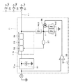
図2は、コントロールユニットCUの内部構成の一例を示す。上述したように、コントロールユニットCUは、高圧入力電源回路11および低圧入力電源回路12を含む構成とされる。高圧入力電源回路11は、AC入力をDC出力に変換するAC−DCコンバータ11aと、電圧V10を45V〜48Vの範囲のDC電圧に降圧するDC−DCコンバータ11bとを含む構成とされる。AC−DCコンバータ11aおよびDC−DCコンバータ11bの方式については、公知のものを適用できる。なお、高圧入力電源回路11にDC電圧のみが供給されるときは、AC−DCコンバータ11aがなくてもよい。
"Internal configuration of control unit"
FIG. 2 shows an example of the internal configuration of the control unit CU. As described above, the control unit CU includes the high-voltage
DC−DCコンバータ11bの入力段および出力段のそれぞれに、電圧センサと、電子スイッチと、電流センサとが接続されている。図2および後述する図5では、電圧センサを四角で、電子スイッチを丸で、電流センサを斜線が付された丸で、それぞれ簡略化して示している。DC−DCコンバータ11bの入力段には、電圧センサ11cと、電子スイッチ11dと、電流センサ11eとが接続されている。DC−DCコンバータ11bの出力段には、電流センサ11fと、電子スイッチ11gと、電圧センサ11hとが接続されている。各センサによって得られるセンサ情報が後述するCPU(Central Processing Unit)13に供給される。各電子スイッチのオン/オフがCPU13によって制御される。
A voltage sensor, an electronic switch, and a current sensor are connected to each of the input stage and the output stage of the DC-
低圧入力電源回路12は、電圧V11を45V〜48Vの範囲のDC電圧に昇圧するDC−DCコンバータ12aを含む構成とされる。低圧入力電源回路12の入力段および出力段のそれぞれに、電圧センサと、電子スイッチと、電流センサとが接続されている。DC−DCコンバータ12aの入力段には、電圧センサ12bと、電子スイッチ12cと、電流センサ12dとが接続されている。DC−DCコンバータ12aの出力段には、電流センサ12eと、電子スイッチ12fと、電圧センサ12gとが接続されている。各センサによって得られるセンサ情報が後述するCPU13に供給される。各スイッチのオン/オフがCPU13よって制御される。
The low-voltage input
なお、図において、センサから延びる矢印が、センサ情報がCPU13に供給されることを示している。電子スイッチに対する矢印は、電子スイッチに対してCPU13による制御がなされることを示している。
In the figure, an arrow extending from the sensor indicates that sensor information is supplied to the
高圧入力電源回路11の出力電圧がダイオードを介して出力される。低圧入力電源回路12の出力電圧がダイオードを介して出力される。高圧入力電源回路11の出力電圧および低圧入力電源回路12の出力電圧が合成され、合成された電圧V12が電力ラインL1を介してバッテリユニットBUに出力される。バッテリユニットBUから供給された電圧V13が、電力ラインL2を介してコントロールユニットCUに供給される。次に、コントロールユニットCUに供給された電圧V13が、電力ラインL3を介して外部機器に供給される。なお、図において、外部機器に供給される電圧を電圧V14として示している。
The output voltage of the high voltage input
電力ラインL3がバッテリユニットBUと接続されてもよい。このような構成により、例えば、バッテリユニットBUaから出力された電力が、電力ラインL2を介してコントロールユニットCUに供給される。供給された電力が電力ラインL3を介してバッテリユニットBUbに供給され、バッテリユニットBUbを充電することができる。なお、図示は省略しているが、電力ラインL2を介してコントロールユニットCUに供給された電力が、電力ラインL1に供給されるようにしてもよい。 The power line L3 may be connected to the battery unit BU. With such a configuration, for example, the power output from the battery unit BUa is supplied to the control unit CU via the power line L2. The supplied power is supplied to the battery unit BUb through the power line L3, and the battery unit BUb can be charged. Although illustration is omitted, the power supplied to the control unit CU via the power line L2 may be supplied to the power line L1.
コントロールユニットCUは、CPU13を含む構成とされる。CPU13は、コントロールユニットCUの各部を制御する。例えば、高圧入力電源回路11および低圧入力電源回路12における電子スイッチをオン/オフする。さらに、CPU13は、各バッテリユニットBUに制御信号を供給する。CPU13は、例えば、バッテリユニットBUの電源をオンさせる制御信号や、充電または放電を指示する制御信号を、バッテリユニットBUに供給する。CPU13は、バッテリユニットBU毎に異なる内容の制御信号を出力することができる。
The control unit CU includes a
CPU13は、バス14を介してメモリ15、D/A(Digital to Analog)変換部16、A/D(Analog to Digital)変換部17および温度センサ18と接続されている。バス14は、例えば、I2Cバスで構成される。メモリ15は、EEPROM(Electrically Erasable and Programmable Read Only Memory)などの不揮発性メモリにより構成される。D/A変換部16は、各種の処理で使用されるデジタル信号をアナログ信号に変換する。
The
CPU13には、電圧センサや電流センサにより測定されたセンサ情報が入力される。センサ情報は、A/D変換部17によってデジタル信号に変換された後に、CPU13に入力される。温度センサ18は、環境温度を測定する。例えば、コントロールユニットCU内部の温度や、コントロールユニットCUの周囲の温度を測定する。
Sensor information measured by a voltage sensor or a current sensor is input to the
CPU13が通信機能を有していてもよい。例えば、CPU13とパーソナルコンピュータ(PC)19との間で通信のやり取りがなされてもよい。パーソナルコンピュータに限らず、インターネットなどのネットワークに接続された機器とCPU13との間で通信がなされるようにしてもよい。
The
「コントロールユニットの電源系統」
図3は、コントロールユニットCUの、主に電源系統に関する構成の一例を示す。高圧入力電源回路11の出力段には、逆流防止用のダイオード20が接続されている。低圧入力電源回路12の出力段には、逆流防止用のダイオード21が接続されている。ダイオード20およびダイオード21により、高圧入力電源回路11および低圧入力電源回路12がOR接続される。高圧入力電源回路11および低圧入力電源回路12の出力が合成されてバッテリユニットBUに供給される。実際には、高圧入力電源回路11および低圧入力電源回路12の出力のうち、電圧が高い一方の出力がバッテリユニットBUに供給されるものの、負荷となるバッテリユニットBUの電力消費量に応じて、両方から電力が供給される状況にもなる。
"Power supply system of control unit"
FIG. 3 shows an example of the configuration of the control unit CU mainly related to the power supply system. A
コントロールユニットCUには、ユーザによって操作可能なメインスイッチSW1が設けられている。メインスイッチSW1がオンされることでCPU13に電力が供給され、コントロールユニットCUが起動する。CPU13に、例えば、コントロールユニットCUに内蔵されるバッテリ22から電力が供給される。バッテリ22は、リチウムイオンバッテリなどの充電可能なバッテリである。バッテリ22からのDC電圧がDC−DCコンバータ23によって、CPU13が動作する電圧に変換される。変換された電圧がCPU13の電源電圧として供給される。このように、コントロールユニットCUの起動時には、バッテリ22が使用される。バッテリ22に対する制御は、例えば、CPU13によってなされる。
The control unit CU is provided with a main switch SW1 that can be operated by the user. When the main switch SW1 is turned on, power is supplied to the
高圧入力電源回路11や低圧入力電源回路12、あるいはバッテリユニットBUから供給される電力によってバッテリ22を充電することができる。バッテリユニットBUから供給された電力がチャージャー回路24に供給される。チャージャー回路24は、DC−DCコンバータを含む構成とされる。バッテリユニットBUから供給された電圧V13がチャージャー回路24によって所定のレベルのDC電圧に変換される。変換されたDC電圧がバッテリ22に供給される。供給されたDC電圧によってバッテリ22が充電される。
The
なお、高圧入力電源回路11や低圧入力電源回路12、あるいはバッテリユニットBUから供給される電圧V13によってCPU13が動作するようにしてもよい。バッテリユニットBUから供給された電圧V13がDC−DCコンバータ25によって所定のレベルの電圧に変換される。変換された電圧が、電源電圧としてCPU13に供給され、CPU13が動作する。
Note that the
コントロールユニットCUが起動した後に、V10およびV11の少なくとも一方が入力されると電圧V12が生成される。電圧V12が、電力ラインL1を介してバッテリユニットBUに供給される。このとき、CPU13は、信号ラインSLを使用してバッテリユニットBUと通信を行う。この通信によって、CPU13は、バッテリユニットBUに対して起動および放電を指示する制御信号を出力する。そして、CPU13は、スイッチSW2をオンする。スイッチSW2は、例えば、FET(Field Effect Transistor)から構成される。IGBT(Insulated Gate Bipolar Transistor)によって構成されてもよい。スイッチSW2がオンされることで、バッテリユニットBUからコントロールユニットCUに電圧V13が供給される。
When at least one of V10 and V11 is input after the control unit CU is activated, a voltage V12 is generated. The voltage V12 is supplied to the battery unit BU via the power line L1. At this time, the
スイッチSW2の出力側には、逆流防止用のダイオード26が接続されている。ダイオード26を接続することにより、太陽電池や風力発電などから供給される不安定な電力が、外部機器に直接供給されることを防止できる。そして、外部機器には、バッテリユニットBUから供給される安定した電力を供給できる。もちろん、安全のために、バッテリユニットBUの最終段にもダイオードを設けてもよい。
A
バッテリユニットBUから供給された電力を外部機器に供給するときは、CPU13は、スイッチSW3をオンする。スイッチSW3がオンされることで、電圧V13に基づく電圧V14が、電力ラインL3を介して外部機器に供給される。なお、電圧V14が他のバッテリユニットBUに供給され、他のバッテリユニットBUのバッテリBが電圧V14によって充電されてもよい。
When supplying the electric power supplied from the battery unit BU to the external device, the
CPU13は、電圧V13または電圧V14の電圧を取得する機能を有する。例えば、電力ラインL2または電力ラインL3に検出抵抗が接続され、検出抵抗の両端の電圧を測定することで、CPU13は、電圧V13または電圧V14の電圧値を取得する。そして、CPU13は、コントロールユニットCUに所定のバッテリユニットおよび所定の負荷が接続された際の電圧変動を監視する。
The
「高圧入力電源回路の構成例」
図4は、高圧入力電源回路の具体的な構成の一例を示す。図4に示すように、高圧入力電源回路11は、DC−DCコンバータ11bと、後述するフィードフォワード制御系とを備えている。図4では、電圧センサ11c、電子スイッチ11d、電流センサ11e、電流センサ11f、電子スイッチ11gおよび電圧センサ11hならびにダイオード20などの図示を省略している。
"Configuration example of high-voltage input power supply circuit"
FIG. 4 shows an example of a specific configuration of the high-voltage input power supply circuit. As shown in FIG. 4, the high-voltage input
低圧入力電源回路12は、DC−DCコンバータ12aが昇圧型のDC−DCコンバータとされること以外は、高圧入力電源回路11の構成とほぼ同様の構成を備えているため、図示および説明を省略する。
The low-voltage
DC−DCコンバータ11bは、例えば、スイッチング素子などを含む一次側回路32と、トランス33と、整流素子などを含む二次側回路34とから構成される。図4に例示するDC−DCコンバータ11bは、電流共振型のコンバータ(LLC共振コンバータ)である。
The DC-
フィードフォワード制御系は、オペアンプ35、トランジスタ36、抵抗Rc1、Rc2およびRc3を含み、フィードフォワード制御系の出力は、例えば、DC−DCコンバータ11bの一次側回路32のドライバに備えられた制御用端子に入力される。DC−DCコンバータ11bは、制御用端子に対する入力電圧が一定となるように、高圧入力電源回路11からの出力電圧を調整する。
The feedforward control system includes an
高圧入力電源回路11がフィードフォワード制御系を備えることにより、高圧入力電源回路11からの出力電圧の値が、あらかじめ設定された範囲内の電圧値となるように調整される。したがって、高圧入力電源回路11を備えるコントロールユニットCUは、例えば、太陽電池などからの入力電圧の変化に応じて出力電圧を変化させる電圧変換装置の機能を有している。
By providing the high-voltage input
図4に示すように、高圧入力電源回路11からは、コンデンサ31を含むAC−DCコンバータ11a、一次側回路32、トランス33、二次側回路34を介して出力電圧が取り出される。AC−DCコンバータ11aは、コントロールユニットCUの外部からの入力が交流電源であるときに配置される力率補正(Power Factor Correction)回路である。
As shown in FIG. 4, the output voltage is extracted from the high-voltage input
コントロールユニットCUからの出力は、電力ラインL1により、バッテリユニットBUに送出される。例えば、個々のバッテリユニットBUa、BUb、BUc、・・・は、逆流防止用のダイオードD1、D2、D3、・・・を介して、出力端子Te1、Te2、Te3、・・・にそれぞれ接続される。 The output from the control unit CU is sent to the battery unit BU through the power line L1. For example, the individual battery units BUa, BUb, BUc,... Are connected to the output terminals Te1, Te2, Te3,... Via the diodes D1, D2, D3,. The
以下、高圧入力電源回路11に備えられたフィードフォワード制御系について説明する。
Hereinafter, the feedforward control system provided in the high-voltage input
オペアンプ35の非反転入力端子に対しては、高圧入力電源回路11への入力電圧をkc倍(kc:数十〜百分の一程度)した電圧が入力される。一方、オペアンプ35の反転入力端子c1に対しては、あらかじめ定められた一定の電圧Vt0をkc倍した電圧が入力されている。オペアンプ35の反転入力端子c1に対する入力電圧(kc×Vt0)は、例えば、D/A変換部16から印加される。電圧Vt0の値は、例えば、D/A変換部16の内蔵メモリに保持され、必要に応じて、電圧Vt0の値を変更することが可能とされている。電圧Vt0の値が、バス14を介してCPU13に接続されたメモリ15に保持され、これをD/A変換部16に転送するようにしてもよい。
A voltage obtained by multiplying the input voltage to the high-voltage input
オペアンプ35の出力端子はトランジスタ36のベースに接続されており、トランジスタ36により、オペアンプ35の非反転入力端子に対する入力電圧と反転入力端子に対する入力電圧との差に応じた電圧−電流変換が行われる。
The output terminal of the
トランジスタ36のエミッタに接続された抵抗Rc2の抵抗値は、抵抗Rc2と並列に接続される抵抗Rc1の抵抗値に対して大とされている。
The resistance value of the resistor Rc2 connected to the emitter of the
例えば、高圧入力電源回路11に対する入力電圧が、あらかじめ定められた一定の電圧Vt0よりも十分に高い電圧であったとする。このとき、トランジスタ36はオンであり、抵抗Rc1および抵抗Rc2の合成抵抗の値が抵抗Rc1の抵抗値より小となるため、図4に示すf点の電位はグラウンド電位に近づく。
For example, the input voltage to the high voltage input
すると、フォトカプラ37を介して接続された、一次側回路32のドライバに備えられた制御用端子に対する入力電圧が低下する。制御用端子に対する入力電圧の低下を検出したDC−DCコンバータ11bは、制御用端子に対する入力電圧が一定となるように、高圧入力電源回路11からの出力電圧を引き上げる。
Then, the input voltage to the control terminal provided in the driver of the
逆に、例えば、コントロールユニットCUに接続された太陽電池の端子電圧が低下し、高圧入力電源回路11に対する入力電圧が、あらかじめ定められた一定の電圧Vt0に近づいたとする。
Conversely, for example, reduces the terminal voltage of the connected solar cell to the control unit CU, the input voltage to the high voltage input
高圧入力電源回路11に対する入力電圧が下がってくると、トランジスタ36の状態が、オンからオフの状態に近づく。トランジスタ36の状態がオンからオフの状態に近づくに伴い、抵抗Rc1および抵抗Rc2には電流が流れにくくなり、図4に示すf点の電位が上昇する。
When the input voltage to the high-voltage input
すると、一次側回路32のドライバに備えられた制御用端子に対する入力電圧が一定に保たれなくなるため、DC−DCコンバータ11bは、制御用端子に対する入力電圧が一定となるように、高圧入力電源回路11からの出力電圧を引き下げる。
Then, since the input voltage to the control terminal provided in the driver of the
すなわち、高圧入力電源回路11は、入力電圧があらかじめ定められた一定の電圧Vt0よりも十分に高い電圧である場合には、出力電圧を引き上げる。また、高圧入力電源回路11は、太陽電池の端子電圧が低下して、入力電圧があらかじめ定められた一定の電圧Vt0に近づくと、出力電圧を引き下げる。このように、高圧入力電源回路11を備えるコントロールユニットCUは、入力電圧の大きさに応じて出力電圧を動的に変化させる。
That is, the high voltage input
さらに、以下に説明するように、高圧入力電源回路11は、コントロールユニットCUの出力側で必要とされる電圧の変化に対しても出力電圧を動的に変化させる。
Further, as will be described below, the high-voltage input
例えば、太陽電池の発電中に、コントロールユニットCUに対して電気的に接続されるバッテリユニットBUの数が増加したとする。すなわち、太陽電池の発電中において、太陽電池からみた負荷が増加したとする。 For example, it is assumed that the number of battery units BU electrically connected to the control unit CU increases during power generation of the solar cell. That is, it is assumed that the load seen from the solar cell increases during the power generation of the solar cell.
この場合、コントロールユニットCUに対して新たにバッテリユニットBUが電気的に接続されることにより、コントロールユニットCUに接続されている太陽電池の端子電圧が下がることになる。すると、高圧入力電源回路11に対する入力電圧が低下するに伴い、トランジスタ36の状態が、オンからオフの状態に近づくこととなり、高圧入力電源回路11からの出力電圧が引き下げられる。
In this case, when the battery unit BU is newly electrically connected to the control unit CU, the terminal voltage of the solar cell connected to the control unit CU is lowered. Then, as the input voltage to the high voltage input
一方、例えば、太陽電池の発電中に、コントロールユニットCUに対して電気的に接続されたバッテリユニットBUの数が減少したとすると、太陽電池からみた負荷が減少するため、コントロールユニットCUに接続された太陽電池の端子電圧が上昇する。高圧入力電源回路11に対する入力電圧が、あらかじめ定められた一定の電圧Vt0よりも十分に高い電圧になると、一次側回路32のドライバに備えられた制御用端子に対する入力電圧が低下し、高圧入力電源回路11からの出力電圧が引き上げられる。
On the other hand, for example, if the number of battery units BU electrically connected to the control unit CU is reduced during power generation of the solar cell, the load seen from the solar cell is reduced, so that the battery is connected to the control unit CU. The terminal voltage of the solar cell increases. When the input voltage to the high-voltage
なお、抵抗Rc1、Rc2およびRc3の抵抗値は、高圧入力電源回路11からの出力電圧の値があらかじめ設定された範囲内の電圧値となるように適宜選択される。すなわち、抵抗Rc1およびRc2の抵抗値により、高圧入力電源回路11からの出力電圧の上限がきめられる。トランジスタ36は、高圧入力電源回路11に対する入力電圧が所定の値を超えているときに、高圧入力電源回路11からの出力電圧の値が、あらかじめ設定された上限の電圧値を超えないようにするために配置されている。
The resistance values of the resistors Rc1, Rc2, and Rc3 are appropriately selected so that the value of the output voltage from the high-voltage input
一方、高圧入力電源回路11からの出力電圧の下限は、後述するように、チャージャー回路41aにおけるフィードフォワード制御系のオペアンプの反転入力端子に対する入力電圧によってきめられる。
On the other hand, the lower limit of the output voltage from the high-voltage input
「バッテリユニットの内部構成」
図5は、バッテリユニットBUの内部構成の一例を示す。ここでは、バッテリユニットBUaを例にして説明する。特に断らない限り、バッテリユニットBUbおよびバッテリユニットBUcは、バッテリユニットBUaと同様の構成とされる。
“Battery unit internal configuration”
FIG. 5 shows an example of the internal configuration of the battery unit BU. Here, the battery unit BUa will be described as an example. Unless otherwise specified, the battery unit BUb and the battery unit BUc have the same configuration as the battery unit BUa.
バッテリユニットBUaは、チャージャー回路41aと、ディスチャージャー回路42aと、バッテリBaとを含む構成とされる。コントロールユニットCUからチャージャー回路41aに対して、電圧V12が供給される。バッテリユニットBUaからの出力である電圧V13が、ディスチャージャー回路42aを介してコントロールユニットCUに供給される。ディスチャージャー回路42aから外部機器に対して、直接、電圧V13が供給されるようにしてもよい。
The battery unit BUa includes a
チャージャー回路41aは、DC−DCコンバータ43aを備える。チャージャー回路41aに入力される電圧V12が、DC−DCコンバータ43aによって所定電圧に変換される。変換された所定電圧がバッテリBaに供給され、バッテリBaが充電される。所定電圧は、バッテリBaの種類等によって異なる。DC−DCコンバータ43aの入力段には、電圧センサ43bと、電子スイッチ43cと、電流センサ43dとが接続されている。DC−DCコンバータ43aの出力段には、電流センサ43eと、電子スイッチ43fと、電圧センサ43gとが接続されている。
The
ディスチャージャー回路42aは、DC−DCコンバータ44aを備える。バッテリBaからディスチャージャー回路42aに供給されるDC電圧が、DC−DCコンバータ44aによって電圧V13に変換される。変換された電圧V13がディスチャージャー回路42aから出力される。DC−DCコンバータ44aの入力段には、電圧センサ44bと、電子スイッチ44cと、電流センサ44dとが接続されている。DC−DCコンバータ44aの出力段には、電流センサ44eと、電子スイッチ44fと、電圧センサ44gとが接続されている。
The
バッテリユニットBUaは、CPU45を備える。CPU45は、バッテリユニットBUの各部を制御する。例えば、電子スイッチのオン/オフを制御する。過充電防止機能や過電流防止機能などの、バッテリBの安全を確保する処理をCPU45が行うようにしてもよい。CPU45は、バス46に接続されている。バス46は、例えば、I2Cバスである。
The battery unit BUa includes a
バス46には、メモリ47と、A/D変換部48と、温度センサ49とが接続されている。メモリ47は、例えば、EEPROMなどの書き換え可能な不揮発性メモリである。A/D変換部48は、例えば、電圧センサや電流センサによって得られるアナログのセンサ情報をデジタル情報に変換する。A/D変換部48によってデジタル信号へと変換されたセンサ情報がCPU45に供給される。温度センサ49は、バッテリユニットBU内の所定箇所の温度を測定する。温度センサ49は、例えば、CPU45が実装される基板の周囲の温度と、チャージャー回路41aおよびディスチャージャー回路42aの温度と、バッテリBaの温度とを測定する。
A
「バッテリユニットの電源系統」
図6は、バッテリユニットBUaの、主に電源系統に関する構成の一例を示す。バッテリユニットBUaには、メインスイッチは設けられていない。バッテリBaとCPU45との間には、スイッチSW5およびDC−DCコンバータ39が接続されている。バッテリBaとディスチャージャー回路42aとの間には、スイッチSW6が接続されている。チャージャー回路41aの入力段には、スイッチSW7が接続されている。ディスチャージャー回路42aの出力段には、スイッチSW8が接続されている。それぞれのスイッチSWは、例えば、FETにより構成される。
"Battery unit power system"
FIG. 6 shows an example of the configuration of the battery unit BUa mainly related to the power supply system. The battery unit BUa is not provided with a main switch. A switch SW5 and a DC-
バッテリユニットBUaは、例えば、コントロールユニットCUからの制御信号によって起動される。コントロールユニットCUから、所定の信号ラインを介して、例えば、ハイレベルの制御信号が常に供給されている。このため、バッテリユニットBUaのポートを所定の信号ラインに接続するだけでハイレベルの制御信号がスイッチSW5に供給され、スイッチSW5がオンされる。スイッチSW5がオンすることで、バッテリユニットBUaが起動する。スイッチSW5がオンすることで、バッテリBaからのDC電圧がDC−DCコンバータ39に供給される。DC−DCコンバータ39によって、CPU45を動作させる電源電圧が生成される。生成された電源電圧がCPU45に供給され、CPU45が動作する。
The battery unit BUa is activated by a control signal from the control unit CU, for example. For example, a high level control signal is always supplied from the control unit CU via a predetermined signal line. Therefore, only by connecting the port of the battery unit BUa to a predetermined signal line, a high-level control signal is supplied to the switch SW5, and the switch SW5 is turned on. When the switch SW5 is turned on, the battery unit BUa is activated. When the switch SW5 is turned on, the DC voltage from the battery Ba is supplied to the DC-
CPU45は、コントロールユニットCUの指示に応じた制御を実行する。コントロールユニットCUからCPU45に対して、例えば、充電指示の制御信号が供給される。充電指示に応じて、CPU45は、スイッチSW6およびスイッチSW8をオフした後にスイッチSW7をオンする。スイッチSW7がオンされることで、コントロールユニットCUから供給される電圧V12が、チャージャー回路41aに供給される。チャージャー回路41aによって電圧V12が所定電圧に変換され、変換された所定電圧によってバッテリBaが充電される。なお、バッテリBに対する充電方法は、バッテリBの種類に応じて適宜変更することができる。
CPU45 performs control according to the instruction | indication of control unit CU. For example, a control signal for charging instructions is supplied from the control unit CU to the
コントロールユニットCUからCPU45に対して、例えば、放電指示の制御信号が供給される。放電指示に応じて、CPU45は、スイッチSW7をオフし、スイッチSW6およびスイッチSW8をオンする。例えば、スイッチSW6をオンしてから、一定時間後にスイッチSW8をオンする。スイッチSW6がオンされることで、バッテリBaからのDC電圧がディスチャージャー回路42aに供給される。ディスチャージャー回路42aによって、バッテリBaからのDC電圧が電圧V13に変換される。変換された電圧V13が、スイッチSW8を介してコントロールユニットCUに供給される。なお、本例では省略しているが、他のバッテリユニットBUからの出力と衝突しないようにするため、スイッチSW8の後段にダイオードを追加するようにしてもよい。
For example, a discharge instruction control signal is supplied from the control unit CU to the
なお、コントロールユニットCUから各バッテリユニットBUに対して、予め充電または放電するタイミングが指示されていれば、バッテリユニットBUのCPU45は、指示されたタイミングに応じて充電または放電の動作を行うことができる。
If the control unit CU has previously instructed each battery unit BU to be charged or discharged, the
なお、CPU45の制御によって、ディスチャージャー回路42aのオン/オフを切り換えることができる(図中のCPU45からディスチャージャー回路42aに出ているON/OFF信号線)。例えば、スイッチSW6の出力側に、図示しないスイッチSW(説明の便宜を考慮して、スイッチSW10と称する)が設けられている。スイッチSW10は、ディスチャージャー回路42aを経由する第1の経路と、ディスチャージャー回路42aを経由しない第2の経路とを切り換えるスイッチである。
Incidentally, the control of the
ディスチャージャー回路42aをオンするときは、CPU45は、スイッチSW10を第1の経路に接続する。これにより、スイッチSW6からの出力がディスチャージャー回路42aを介してスイッチSW8に供給される。ディスチャージャー回路42aをオフするときは、CPU45は、スイッチSW10を第2の経路に接続する。これにより、スイッチSW6からの出力がディスチャージャー回路42aを介さずに直接、スイッチSW8に供給される。
When turning on the
「チャージャー回路の構成例」
図7は、バッテリユニットにおけるチャージャー回路の具体的な構成の一例を示す。図7に示すように、チャージャー回路41aは、DC−DCコンバータ43aと、後述するフィードフォワード制御系およびフィードバック制御系とを備えている。なお、図7では、電圧センサ43b、電子スイッチ43c、電流センサ43d、電流センサ43e、電子スイッチ43f、電圧センサ43gならびにスイッチSW7などの図示を省略している。
“Charger circuit configuration example”
FIG. 7 shows an example of a specific configuration of the charger circuit in the battery unit. As shown in FIG. 7, the
各バッテリユニットBUにおけるチャージャー回路も、図7に示すチャージャー回路41aの構成とほぼ同様の構成を備えている。
The charger circuit in each battery unit BU has substantially the same configuration as the configuration of the
DC−DCコンバータ43aは、例えば、トランジスタ51、コイル52、制御用IC(Integrated Circuit)53などから構成される。トランジスタ51は、制御用IC53により制御される。
The DC-
フィードフォワード制御系は、高圧入力電源回路11と同様に、オペアンプ55、トランジスタ56、抵抗Rb1、Rb2およびRb3を含む。フィードフォワード制御系の出力は、例えば、DC−DCコンバータ43aの制御用IC53に備えられた制御用端子に入力される。DC−DCコンバータ43a中の制御用IC53は、制御用端子に対する入力電圧が一定となるように、チャージャー回路41aからの出力電圧を調整する。
Similarly to the high-voltage input
すなわち、チャージャー回路41aに備えられたフィードフォワード制御系は、高圧入力電源回路11に備えられたフィードフォワード制御系と同様に作用する。
That is, the feedforward control system provided in the
チャージャー回路41aがフィードフォワード制御系を備えることにより、チャージャー回路41aからの出力電圧の値が、あらかじめ設定された範囲内の電圧値となるように調整される。チャージャー回路からの出力電圧の値が、あらかじめ設定された範囲内の電圧値に調整されることにより、コントロールユニットCUに電気的に接続された各バッテリBに対する充電電流が、高圧入力電源回路11からの入力電圧の変化に応じて調整される。したがって、チャージャー回路を備えるバッテリユニットBUは、各バッテリBに対する充電レートを変化させる充電装置の機能を有している。
When the
コントロールユニットCUに電気的に接続された各バッテリBに対する充電レートが変化させられることにより、各バッテリユニットBUのチャージャー回路に対する入力電圧の値(高圧入力電源回路11または低圧入力電源回路12からの出力電圧の値といってもよい。)が、あらかじめ設定された範囲内の電圧値となるように調整される。
By changing the charging rate for each battery B electrically connected to the control unit CU, the value of the input voltage to the charger circuit of each battery unit BU (the output from the high voltage
チャージャー回路41aへの入力は、例えば、上述したコントロールユニットCUの高圧入力電源回路11または低圧入力電源回路12からの出力である。したがって、例えば、図4に示す端子Te1、Te2、Te3、・・・のいずれかと、チャージャー回路41aの入力端子とが接続されている。
The input to the
図7に示すように、チャージャー回路41aからは、DC−DCコンバータ43a、電流センサ54、フィルタ55を介して出力電圧が取り出される。チャージャー回路41aの端子Tb1には、バッテリBaが接続される。すなわち、チャージャー回路41aからの出力は、バッテリBaに対する入力となる。
As shown in FIG. 7, the output voltage is taken out from the
後述するように、各チャージャー回路からの出力電圧の値は、各チャージャー回路に接続されるバッテリの種類に応じて、あらかじめ設定された範囲内の電圧値となるように調整されている。各チャージャー回路からの出力電圧の範囲は、抵抗Rb1、Rb2およびRb3の抵抗値が適宜選択されることにより調整される。 As will be described later, the value of the output voltage from each charger circuit is adjusted to be a voltage value within a preset range in accordance with the type of battery connected to each charger circuit. The range of the output voltage from each charger circuit is adjusted by appropriately selecting the resistance values of the resistors Rb1, Rb2, and Rb3.
このように、各チャージャー回路からの出力電圧の範囲が、チャージャー回路に接続されるバッテリの種類に応じて個別にきめられるため、バッテリユニットBUに備えられるバッテリBの種類は特に限定されない。各チャージャー回路内の抵抗Rb1、Rb2およびRb3の抵抗値を、接続されるバッテリBの種類に応じて適宜選択すればよいからである。 Thus, since the range of the output voltage from each charger circuit is determined individually according to the type of the battery connected to the charger circuit, the type of the battery B provided in the battery unit BU is not particularly limited. This is because the resistance values of the resistors Rb1, Rb2, and Rb3 in each charger circuit may be appropriately selected according to the type of the battery B to be connected.
なお、図7ではフィードフォワード制御系の出力が制御用IC53の制御用端子に入力される構成を例示したが、バッテリユニットBUのCPU45が、制御用IC53の制御用端子に入力を与えるようにしてもよい。例えば、バッテリユニットBUのCPU45が、信号ラインSLを介してバッテリユニットBUに対する入力電圧に関する情報をコントロールユニットCUのCPU13から取得するようにしてもよい。コントロールユニットCUのCPU13は、電圧センサ11hや電圧センサ12gなどの測定結果から、バッテリユニットBUに対する入力電圧に関する情報を取得することが可能である。
7 illustrates the configuration in which the output of the feedforward control system is input to the control terminal of the
以下、チャージャー回路41aに備えられたフィードフォワード制御系について説明する。
Hereinafter, the feedforward control system provided in the
オペアンプ55の非反転入力端子に対する入力は、チャージャー回路41aへの入力電圧をkb倍(kb:数十〜百分の一程度)した電圧とされる。一方、オペアンプ55の反転入力端子b1に対する入力は、高圧入力電源回路11または低圧入力電源回路12からの出力電圧の下限として設定しようとする電圧Vbをkb倍した電圧である。オペアンプ55の反転入力端子b1に対する入力電圧(kb×Vb)は、例えば、CPU45から印加される。
The input to the non-inverting input terminal of the
したがって、チャージャー回路41aに備えられたフィードフォワード制御系は、チャージャー回路41aに対する入力電圧が、あらかじめ定められた一定の電圧Vbよりも十分に高い電圧である場合に、チャージャー回路41aからの出力電圧を引き上げる。また、チャージャー回路41aに対する入力電圧が、あらかじめ定められた一定の電圧Vbに近づくと、フィードフォワード制御系は、チャージャー回路41aからの出力電圧を引き下げる。
Therefore, the feedforward control system provided in the
トランジスタ56は、図4に示すトランジスタ36と同様に、チャージャー回路41aに対する入力電圧が所定の値を超えているときに、チャージャー回路41aからの出力電圧の値が、あらかじめ設定された上限を超えないようにするために配置されている。なお、チャージャー回路41aからの出力電圧の値の範囲は、抵抗Rb1、Rb2およびRb3の抵抗値の組み合わせによってきまる。そのため、抵抗Rb1、Rb2およびRb3の抵抗値は、各チャージャー回路に接続されるバッテリBの種類に応じて調整される。
Similarly to the
また、チャージャー回路41aは、上述したように、フィードバック制御系をも備えている。フィードバック制御系は、例えば、電流センサ54、オペアンプ57およびトランジスタ58などから構成される。
The
バッテリBaに供給される電流量があらかじめ設定された規定値を超えると、フィードバック制御系により、チャージャー回路41aからの出力電圧が引き下げられ、バッテリBaに供給される電流量が制限される。フィードバック制御系による、バッテリBaに供給される電流量の制限の程度は、各チャージャー回路に接続されるバッテリBの定格にあわせてきめられる。
When the amount of current supplied to the battery Ba exceeds a preset specified value, the output voltage from the
フィードフォワード制御系またはフィードバック制御系により、チャージャー回路41aからの出力電圧が引き下げられると、バッテリBaに供給される電流量が制限されることになる。バッテリBaに供給される電流量が制限されると、結果として、チャージャー回路41aに接続されたバッテリBaに対する充電が減速される。
When the output voltage from the
次に、本開示の実施形態において実行されてもよい協調制御を説明する前に、MPPT制御と、電圧追従法による制御とを例にとり、それぞれの制御方式について説明する。 Next, before describing cooperative control that may be executed in the embodiment of the present disclosure, each control method will be described by taking MPPT control and control by a voltage tracking method as examples.
「MPPT制御」
まず、以下に、MPPT制御の概略について説明を行う。
"MPPT control"
First, an outline of MPPT control will be described below.
図8Aは、太陽電池の電圧−電流特性を示すグラフである。図8A中、縦軸は、太陽電池の端子電流を表し、横軸は、太陽電池の端子電圧を表している。図8A中、Iscは、光照射時において、太陽電池の端子間を短絡したときの出力電流を表し、Vocは、光照射時において、太陽電池の端子間を開放したときの出力電圧を表している。IscおよびVocは、それぞれ短絡電流および開放電圧と呼ばれる。 FIG. 8A is a graph showing voltage-current characteristics of a solar cell. In FIG. 8A, the vertical axis represents the terminal current of the solar cell, and the horizontal axis represents the terminal voltage of the solar cell. In FIG. 8A, Isc represents the output current when the terminals of the solar cells are short-circuited during light irradiation, and Voc represents the output voltage when the terminals of the solar cells are opened during light irradiation. Yes. Isc and Voc are called short circuit current and open circuit voltage, respectively.
図8Aに示すように、光照射時において、太陽電池の端子電流は、太陽電池の端子間を短絡したときが最大であり、このとき、太陽電池の端子電圧はほぼ0Vである。一方、光照射時において、太陽電池の端子電圧は、太陽電池の端子間を開放したときが最大であり、このとき、太陽電池の端子電流はほぼ0Aである。 As shown in FIG. 8A, during light irradiation, the terminal current of the solar cell is maximum when the terminals of the solar cell are short-circuited, and at this time, the terminal voltage of the solar cell is approximately 0V. On the other hand, at the time of light irradiation, the terminal voltage of the solar cell is maximum when the terminals of the solar cell are opened, and at this time, the terminal current of the solar cell is approximately 0A.
いま、太陽電池の電圧−電流特性を示すグラフが、図8Aに示す曲線C1で表されるとする。ここで、太陽電池に対して負荷を接続したとすると、接続される負荷の必要としている消費電力により、太陽電池から取りだされる電圧と電流がきまる。このときの太陽電池の端子電圧および端子電流の組により表される、曲線C1上の点を、太陽電池の動作点という。なお、図8Aは、動作点の位置を模式的に示したものであり、実際の動作点の位置を示すものではない。本開示の他の図における動作点に関しても、同様とする。 Now, suppose that the graph which shows the voltage-current characteristic of a solar cell is represented by the curve C1 shown to FIG. Here, if a load is connected to the solar cell, the voltage and current taken from the solar cell are determined by the power consumption required by the connected load. A point on the curve C1 represented by a set of terminal voltage and terminal current of the solar cell at this time is referred to as an operating point of the solar cell. FIG. 8A schematically shows the position of the operating point, and does not show the actual position of the operating point. The same applies to operating points in other figures of the present disclosure.
太陽電池の電圧−電流特性を表す曲線上において動作点を変化させると、端子電圧と端子電流との積、すなわち発電電力が最大となる端子電圧Vaおよび端子電流Iaの組が見つかる。太陽電池により得られる電力が最大となる端子電圧Vaおよび端子電流Iaの組により表される点は、太陽電池の最適動作点と呼ばれる。 When the operating point is changed on the curve representing the voltage-current characteristics of the solar cell, a product of the terminal voltage and the terminal current, that is, a set of the terminal voltage Va and the terminal current Ia that maximizes the generated power is found. The point represented by the set of the terminal voltage Va and the terminal current Ia at which the electric power obtained by the solar battery is maximized is called the optimum operating point of the solar battery.
太陽電池の電圧−電流特性を示すグラフが図8Aに示す曲線C1で表されるとき、太陽電池から得られる最大の電力は、最適動作点を与えるVaとIaとの積により求められる。すなわち、太陽電池の電圧−電流特性を示すグラフが図8Aに示す曲線C1で表されるとき、太陽電池から得られる最大の電力は、図8Aにおいて網掛けで示された領域の面積(Va×Ia)により表される。なお、(Va×Ia)を(Voc×Isc)で割った量がフィルファクタである。 When the graph showing the voltage-current characteristics of the solar cell is represented by the curve C1 shown in FIG. 8A, the maximum power obtained from the solar cell is obtained by the product of Va and Ia giving the optimum operating point. That is, when the graph showing the voltage-current characteristics of the solar cell is represented by the curve C1 shown in FIG. 8A, the maximum power obtained from the solar cell is the area of the region (Va × Ia). An amount obtained by dividing (Va × Ia) by (Voc × Isc) is a fill factor.
最適動作点は、太陽電池に接続される負荷の必要としている電力により変化し、最適動作点を表す点PAは、太陽電池に接続される負荷の必要としている電力の変化にしたがって曲線C1上を動く。負荷の必要としている電力量が少ない場合、負荷への電流の供給は、最適動作点における端子電流よりも少ない電流で事足りる。そのため、このときの太陽電池の端子電圧の値は、最適動作点における電圧値よりも高い値になる。一方、負荷の必要としている電力量が、最適動作点で供給できる電力量よりも大きい場合には、この時点の照度で提供できる電力を超えているため、太陽電池の端子電圧が0まで低下していくものと考えられる。 The optimum operating point changes depending on the power required by the load connected to the solar cell, and the point P A representing the optimum operating point is on the curve C1 according to the change in the power required by the load connected to the solar cell. Move. When the amount of power required by the load is small, it is sufficient to supply current to the load with less current than the terminal current at the optimum operating point. Therefore, the value of the terminal voltage of the solar cell at this time is higher than the voltage value at the optimum operating point. On the other hand, when the amount of power required by the load is larger than the amount of power that can be supplied at the optimum operating point, the power that can be provided by the illuminance at this point is exceeded, so the terminal voltage of the solar cell decreases to zero. It is thought that it will go.
図8Aに示す曲線C2およびC3は、例えば、太陽電池に対する照度が変化した場合における、太陽電池の電圧−電流特性を示している。例えば、図8Aに示す曲線C2は、太陽電池に対する照度が増加した場合における電圧−電流特性に対応し、図8Aに示す曲線C3は、太陽電池に対する照度が減少した場合における電圧−電流特性に対応する。 Curves C2 and C3 shown in FIG. 8A show the voltage-current characteristics of the solar cell when the illuminance on the solar cell changes, for example. For example, the curve C2 shown in FIG. 8A corresponds to the voltage-current characteristic when the illuminance on the solar cell increases, and the curve C3 shown in FIG. 8A corresponds to the voltage-current characteristic when the illuminance on the solar cell decreases. To do.
例えば、太陽電池に対する照度が増加し、太陽電池の電圧−電流特性を表す曲線が、曲線C1から曲線C2に変化したとすると、最適動作点も太陽電池に対する照度の増加に伴って変化する。なお、このとき、最適動作点は、曲線C1上の点から曲線C2上の点にうつる。 For example, if the illuminance on the solar cell increases and the curve representing the voltage-current characteristics of the solar cell changes from the curve C1 to the curve C2, the optimum operating point also changes with the increase in illuminance on the solar cell. At this time, the optimum operating point changes from a point on the curve C1 to a point on the curve C2.
MPPT制御とは、太陽電池の電圧−電流特性を表す曲線の変化に対して最適動作点を求め、太陽電池から得られる電力が最大となるように、太陽電池の端子電圧(または端子電流)を制御することにほかならない。 With MPPT control, the optimum operating point is obtained with respect to the change in the curve representing the voltage-current characteristics of the solar cell, and the terminal voltage (or terminal current) of the solar cell is set so that the power obtained from the solar cell becomes maximum. There is nothing but control.
図8Bは、ある曲線により太陽電池の電圧−電流特性が表される場合における、太陽電池の端子電圧と太陽電池の発電電力との関係を表したグラフ(P−V曲線)である。 FIG. 8B is a graph (PV curve) showing the relationship between the terminal voltage of the solar cell and the generated power of the solar cell when the voltage-current characteristic of the solar cell is expressed by a certain curve.
図8Bに示すように、最大動作点を与える端子電圧において、太陽電池の発電電力が最大値Pmaxをとるものとすると、最大動作点を与える端子電圧は、山登り法と呼ばれる手法により求めることができる。以下に説明する一連の手順は、一般的には、太陽電池と、電力系統との間に接続されるパワーコンディショナー(power conditioner)のCPUなどにより実行される。 As shown in FIG. 8B, assuming that the generated power of the solar cell takes the maximum value Pmax at the terminal voltage giving the maximum operating point, the terminal voltage giving the maximum operating point can be obtained by a technique called a hill-climbing method. . A series of procedures described below is generally executed by a CPU of a power conditioner connected between a solar cell and a power system.
例えば、まず、太陽電池から入力される電圧の初期値をV0として、このときの発電電力P0が計算される。次に、V1=V0+ε(ここではε>0とする。)として、太陽電池から入力される電圧がεだけ増加させられる。次に、太陽電池から入力される電圧をV1として、このときの発電電力P1が計算される。次に、得られたP0とP1とが比較され、P1>P0である場合には、V2=V1+εとして、太陽電池から入力される電圧がεだけ増加させられる。次に、太陽電池から入力される電圧をV2として、このときの発電電力P2が計算される。次に、得られたP1とP2とが比較され、P2>P1である場合には、V3=V2+εとして、太陽電池から入力される電圧がεだけ増加させられる。次に、太陽電池から入力される電圧をV3として、このときの発電電力P3が計算される。 For example, first, the initial value of the voltage input from the solar cell is set as V 0 , and the generated power P 0 at this time is calculated. Next, as V 1 = V 0 + ε (here, ε> 0), the voltage input from the solar cell is increased by ε. Then, the voltage inputted from the solar cell is V 1, the generated power P 1 at this time is calculated. Next, the obtained P 0 and P 1 are compared, and when P 1 > P 0 , the voltage input from the solar cell is increased by ε as V 2 = V 1 + ε. Next, the generated power P 2 at this time is calculated with the voltage input from the solar cell as V 2 . Next, the obtained P 1 and P 2 are compared, and when P 2 > P 1 , the voltage input from the solar cell is increased by ε as V 3 = V 2 + ε. Next, assuming that the voltage input from the solar cell is V 3 , the generated power P 3 at this time is calculated.
ここで、P3<P2であったとすると、最大動作点を与える端子電圧は、V2とV3との間にある。このように、εの大きさを調節することにより、任意の精度で最大動作点を与える端子電圧を求めることができる。上述した手順に、二分法(bisection method algorithm)を適用してもよい。なお、太陽電池の光照射面に部分的に影ができたときなど、P−V曲線が2以上のピークを有していると単純な山登り法では対応できないため、制御プログラムに工夫が必要である。 Here, assuming that P 3 <P 2 , the terminal voltage giving the maximum operating point is between V 2 and V 3 . In this way, by adjusting the magnitude of ε, the terminal voltage that gives the maximum operating point can be obtained with an arbitrary accuracy. A bisection method algorithm may be applied to the above-described procedure. It should be noted that if the PV curve has two or more peaks, such as when there is a partial shadow on the light irradiation surface of the solar cell, the simple hill-climbing method cannot be used, and thus the control program must be devised. is there.
MPPT制御によれば、太陽電池からみた負荷が常に最適になるように端子電圧が調整されるため、それぞれの気象条件下で、太陽電池から最大の電力を取り出すことができる。その一方で、最大動作点を与える端子電圧の計算にアナログ/デジタル変換(A/D変換)が必要とされるほか、計算に乗算が含まれるために、制御に時間を要してしまう。そのため、MPPT制御では、空が急に曇りだして太陽電池に対する照度が急激に変化したときなど、太陽電池に対する照度の急激な変化に対応できないときがある。 According to the MPPT control, the terminal voltage is adjusted so that the load viewed from the solar cell is always optimal, and thus the maximum electric power can be extracted from the solar cell under each weather condition. On the other hand, analog / digital conversion (A / D conversion) is required for the calculation of the terminal voltage that gives the maximum operating point, and since the calculation includes multiplication, control takes time. Therefore, in the MPPT control, there are cases where it is not possible to cope with a sudden change in the illuminance on the solar cell, such as when the sky suddenly becomes cloudy and the illuminance on the solar cell changes abruptly.
「電圧追従法による制御」
ここで、図8Aに示す曲線C1〜C3を比較すると、太陽電池に対する照度の変化(電圧−電流特性を表す曲線の変化といってもよい。)に対して、開放電圧Vocの変化は、短絡電流Iscの変化と比較して小さい。また、いずれの太陽電池もよく似た電圧−電流特性を示し、最大動作点を与える端子電圧は、結晶シリコン太陽電池の場合、開放電圧のおよそ80%の付近にあることが知られている。したがって、太陽電池の端子電圧として適当な電圧値を設定し、太陽電池の端子電圧が、その設定された電圧値となるようにコンバータの出力電流を調整すれば、太陽電池から効率よく電力を取り出せると予想される。このような電流制限による制御は、電圧追従法と呼ばれる。
"Control by voltage tracking method"
Here, when the curves C1 to C3 shown in FIG. 8A are compared, the change in the open voltage Voc is short-circuited with respect to the change in illuminance with respect to the solar cell (which may be referred to as a change in the curve representing the voltage-current characteristics). Small compared to the change in current Isc. In addition, it is known that the terminal voltage giving the maximum operating point is in the vicinity of about 80% of the open-circuit voltage in the case of a crystalline silicon solar cell, in which all the solar cells show similar voltage-current characteristics. Therefore, if an appropriate voltage value is set as the terminal voltage of the solar cell and the output current of the converter is adjusted so that the terminal voltage of the solar cell becomes the set voltage value, power can be efficiently extracted from the solar cell. It is expected to be. Such control by current limitation is called a voltage tracking method.
以下に、電圧追従法による制御の概略を説明する。前提として、太陽電池とパワーコンディショナーとの間にスイッチング素子が配置され、太陽電池とスイッチング素子との間に電圧測定手段が配置されているものとする。また、太陽電池は、光照射がされた状態にあるものとする。 Hereinafter, an outline of control by the voltage tracking method will be described. As a premise, it is assumed that a switching element is disposed between the solar cell and the power conditioner, and a voltage measuring unit is disposed between the solar cell and the switching element. In addition, the solar cell is in a state where light is irradiated.
まず、スイッチング素子がオフとされ、スイッチング素子のオフから所定の時間が経過した時に、電圧測定手段により太陽電池の端子電圧が測定される。スイッチング素子のオフから太陽電池の端子電圧の測定までに所定の時間の経過を待つのは、太陽電池の端子電圧が安定するのを待つためである。このときの端子電圧は、開放電圧Vocである。 First, the switching element is turned off, and when a predetermined time has elapsed since the switching element was turned off, the terminal voltage of the solar cell is measured by the voltage measuring means. The reason for waiting for the elapse of a predetermined time from the turning-off of the switching element to the measurement of the terminal voltage of the solar cell is to wait for the terminal voltage of the solar cell to stabilize. The terminal voltage at this time is the open circuit voltage Voc.
次に、測定により得られた開放電圧Vocの例えば80%の電圧値が、目標電圧値として計算され、目標電圧値がメモリなどに一時的に保持される。次に、スイッチング素子がオンとされ、パワーコンディショナー内のコンバータへの通電が開始される。このとき、太陽電池の端子電圧が、目標電圧値となるように、コンバータの出力電流が調整される。上述した一連の手順が、任意の時間間隔で実行される。 Next, for example, a voltage value of 80% of the open circuit voltage Voc obtained by the measurement is calculated as a target voltage value, and the target voltage value is temporarily held in a memory or the like. Next, the switching element is turned on, and energization to the converter in the power conditioner is started. At this time, the output current of the converter is adjusted so that the terminal voltage of the solar cell becomes the target voltage value. The series of procedures described above are executed at arbitrary time intervals.
電圧追従法による制御は、MPPT制御と比較して、太陽電池により得られる電力の損失が大きいが、簡単な回路で実現でき、低コストであるため、コンバータを備えるパワーコンディショナーを、安価なものとできる。 Compared with MPPT control, the voltage tracking method has a large loss of power obtained by solar cells, but it can be realized with a simple circuit and is low in cost. Therefore, a power conditioner equipped with a converter is inexpensive. it can.
図9Aは、太陽電池の電圧−電流特性を表す曲線の変化に対する動作点の変化を説明するための図である。図9A中、縦軸は、太陽電池の端子電流を表し、横軸は、太陽電池の端子電圧を表している。また、図9A中の白丸は、MPPT制御を行ったときの動作点を表し、図9A中の黒丸は、電圧追従法による制御を行ったときの動作点を表している。 FIG. 9A is a diagram for explaining the change of the operating point with respect to the change of the curve representing the voltage-current characteristic of the solar cell. In FIG. 9A, the vertical axis represents the terminal current of the solar cell, and the horizontal axis represents the terminal voltage of the solar cell. Further, white circles in FIG. 9A represent operating points when MPPT control is performed, and black circles in FIG. 9A represent operating points when control by the voltage tracking method is performed.
いま、太陽電池の電圧−電流特性を表す曲線が、曲線C5であったとする。次に、太陽電池に対する照度の変化に伴い、太陽電池の電圧−電流特性を表す曲線が、曲線C5からC8に順に変化したとすると、それぞれの制御方式による動作点も太陽電池の電圧−電流特性を表す曲線の変化に伴って変化する。なお、太陽電池への照度の変化に対する開放電圧Vocの変化が小さいため、図9A中においては、電圧追従法による制御を行ったときの目標電圧値をほぼ一定の値Vsとみなしている。 Now, it is assumed that the curve representing the voltage-current characteristics of the solar cell is the curve C5. Next, assuming that the curve representing the voltage-current characteristic of the solar cell changes in order from the curve C5 to C8 as the illuminance changes with respect to the solar cell, the operating point by each control method is also the voltage-current characteristic of the solar cell. It changes with the change of the curve that represents. In addition, since the change of the open circuit voltage Voc with respect to the change of the illumination intensity to a solar cell is small, in FIG. 9A, the target voltage value when performing control by the voltage tracking method is regarded as a substantially constant value Vs.
図9Aからわかるように、太陽電池の電圧−電流特性を表す曲線が曲線C6である場合には、MPPT制御の動作点と電圧追従法による制御の動作点との間の乖離の度合いは小さい。そのため、太陽電池の電圧−電流特性を表す曲線が曲線C6である場合には、いずれの制御の場合においても、太陽電池により得られる発電電力に大きな違いはないと考えられる。 As can be seen from FIG. 9A, when the curve representing the voltage-current characteristic of the solar cell is the curve C6, the degree of divergence between the MPPT control operating point and the voltage tracking method operating point is small. Therefore, when the curve representing the voltage-current characteristic of the solar cell is the curve C6, it is considered that there is no significant difference in the generated power obtained by the solar cell in any control.
一方、太陽電池の電圧−電流特性を表す曲線が曲線C8である場合には、MPPT制御の動作点と電圧追従法による制御の動作点との間の乖離の度合いが大きい。例えば、図9Aに示すように、MPPT制御を適用したときの端子電圧と電圧追従法による制御を適用したときの端子電圧との差△V6および△V8を比較すると、△V6<△V8となっている。そのため、太陽電池の電圧−電流特性を表す曲線が曲線C8である場合には、MPPT制御を適用したときに太陽電池から得られる発電電力と電圧追従法による制御を適用したときに太陽電池から得られる発電電力との差は大きい。 On the other hand, when the curve representing the voltage-current characteristics of the solar cell is the curve C8, the degree of divergence between the operating point of MPPT control and the operating point of control by the voltage tracking method is large. For example, as shown in FIG. 9A, when the differences ΔV6 and ΔV8 between the terminal voltage when the MPPT control is applied and the terminal voltage when the control by the voltage tracking method is applied, ΔV6 < ΔV8 is obtained. ing. Therefore, when the curve representing the voltage-current characteristic of the solar cell is the curve C8, the generated power obtained from the solar cell when the MPPT control is applied and the control obtained by the voltage tracking method are obtained from the solar cell. The difference with the generated power is large.
「コントロールユニットおよびバッテリユニットの協調制御」
次に、コントロールユニットおよびバッテリユニットの協調制御の概略を説明する。以下、コントロールユニットおよびバッテリユニットの協調(連動)による制御を、協調制御と適宜称する。
"Coordinated control of control unit and battery unit"
Next, an outline of cooperative control of the control unit and the battery unit will be described. Hereinafter, control by cooperation (interlocking) of the control unit and the battery unit is appropriately referred to as cooperative control.
図9Bは、コントロールユニットおよび複数のバッテリユニットにより協調制御を行う制御システムの構成例を示すブロック図である。 FIG. 9B is a block diagram illustrating a configuration example of a control system that performs cooperative control using a control unit and a plurality of battery units.
図9Bに示すように、例えば、コントロールユニットCUには、チャージャー回路およびバッテリの組を備える1または複数のバッテリユニットBUが接続される。図9Bに示すように、1または複数のバッテリユニットBUは、電力ラインL1に対して並列に接続されている。なお、図9BではコントロールユニットCUが1つの場合を例示したが、制御システムがコントロールユニットCUを複数備える場合も同様に、1または複数のコントロールユニットCUは、電力ラインL1に対して並列に接続される。 As shown in FIG. 9B, for example, one or a plurality of battery units BU including a charger circuit and a battery set are connected to the control unit CU. As shown in FIG. 9B, one or more battery units BU are connected in parallel to the power line L1. 9B illustrates the case where there is one control unit CU. Similarly, when the control system includes a plurality of control units CU, one or more control units CU are connected in parallel to the power line L1. The
一般的には、太陽電池から得られた電力により1台のバッテリの充電を行おうとする場合、太陽電池とバッテリとの間に介在されたパワーコンディショナーにより、上述したMPPT制御または電圧追従法による制御が実行される。該1台のバッテリには、複数のバッテリが内包されて一体として動作する物も含まれるが、該1台のバッテリは、複数のバッテリとはいえ、単一の種類からなることが一般的である。言い換えれば、上述したMPPT制御または電圧追従法による制御は、太陽電池と、1台のバッテリとの間に接続されるパワーコンディショナーの単体で実行されることが想定されている。そして、充電中における、充電の対象となるバッテリの台数、構成(並列、直列等の接続の態様)には変化がなく、充電中における、充電の対象となるバッテリの台数、構成は、一般に固定されている。 In general, when one battery is charged with electric power obtained from a solar cell, the above-described MPPT control or voltage tracking method is controlled by a power conditioner interposed between the solar cell and the battery. Is executed. The single battery includes a plurality of batteries that operate as a single unit, but the single battery is generally composed of a single type although it is a plurality of batteries. is there. In other words, it is assumed that the above-described MPPT control or control by the voltage tracking method is executed by a single power conditioner connected between the solar cell and one battery. There is no change in the number and configuration of batteries to be charged during charging (a mode of connection such as parallel and series), and the number and configuration of batteries to be charged during charging are generally fixed. Has been.
一方、協調制御においては、コントロールユニットCUおよび複数のバッテリユニットBUa、BUb、BUc、・・・のそれぞれが、コントロールユニットCUの出力電圧と、複数個のバッテリユニットBUの必要とする電圧とのバランスがとれるように自律的に制御を行う。上述したように、バッテリユニットBUa、BUb、BUc、・・・に内包されるバッテリBは、いずれの種類でもよい。すなわち、本開示によるコントロールユニットCUは、複数種のバッテリBに対する協調制御を行うことが可能とされる。 On the other hand, in cooperative control, each of the control unit CU and the plurality of battery units BUa, BUb, BUc,... Balances the output voltage of the control unit CU and the voltage required by the plurality of battery units BU. Control autonomously so that it can be removed. As described above, the battery B included in the battery units BUa, BUb, BUc,... That is, the control unit CU according to the present disclosure can perform cooperative control on a plurality of types of batteries B.
さらに、図9Bに示す構成例では、個々のバッテリユニットBUの着脱も自在であり、太陽電池の発電中に、コントロールユニットCUに接続されるバッテリユニットBUの数も変化しうる。図9Bに示す構成例では、太陽電池の発電中において、太陽電池からみた負荷も変化しうるが、協調制御によれば、太陽電池に対する照度の変化のみならず、太陽電池の発電中における、太陽電池からみた負荷の変化にも対応が可能である。これは、従来の構成にはなかった大きな特徴の一つである。 Furthermore, in the configuration example shown in FIG. 9B, the individual battery units BU can be attached and detached freely, and the number of battery units BU connected to the control unit CU can be changed during the power generation of the solar cell. In the configuration example shown in FIG. 9B, the load seen from the solar cell can also change during the power generation of the solar cell. However, according to the cooperative control, not only the illuminance change to the solar cell but also the solar cell during the power generation of the solar cell. It is possible to cope with changes in the load as seen from the battery. This is one of the major features not found in the conventional configuration.
上述したコントロールユニットCUとバッテリユニットBUとを接続することにより、コントロールユニットCUからの供給能力に応じて充電レートを動的に変化させる制御システムを構築することが可能となる。以下、協調制御の一例についての説明を行う。なお、以下の説明では、初期の状態において、コントロールユニットCUに対して1のバッテリユニットBUaが接続された制御システムを例にとるが、コントロールユニットCUに対して複数のバッテリユニットBUが接続されている場合も同様である。 By connecting the control unit CU and the battery unit BU described above, it is possible to construct a control system that dynamically changes the charge rate according to the supply capability from the control unit CU. Hereinafter, an example of cooperative control will be described. In the following description, a control system in which one battery unit BUa is connected to the control unit CU in the initial state is taken as an example, but a plurality of battery units BU are connected to the control unit CU. The same applies to the case where there is.
例えば、コントロールユニットCUの入力側に太陽電池が、出力側にバッテリユニットBUaが接続されているとする。また、例えば、太陽電池の出力電圧の上限が100Vであるものとし、太陽電池の出力電圧の下限を75Vに抑えたいとする。すなわち、Vt0=75Vと設定されており、オペアンプ35の反転入力端子に対する入力電圧が、(kc・75)Vであるとする。
For example, it is assumed that a solar cell is connected to the input side of the control unit CU and a battery unit BUa is connected to the output side. Further, for example, it is assumed that the upper limit of the output voltage of the solar cell is 100V, and the lower limit of the output voltage of the solar cell is desired to be 75V. That is, it is assumed that Vt 0 = 75V, and the input voltage to the inverting input terminal of the
また、コントロールユニットCUからの出力電圧の上限および下限が、例えば、48Vおよび45Vにそれぞれ設定されているものとする。すなわち、Vb=45Vと設定されており、オペアンプ55の反転入力端子に対する入力電圧が、(kb×45)Vであるとする。なお、コントロールユニットCUからの出力電圧の上限である48Vという値は、高圧入力電源回路11内の抵抗Rc1およびRc2を適宜選択することにより調整されている。言い換えれば、コントロールユニットCUからの出力の目標電圧値が、48Vに設定されているものとする。
In addition, it is assumed that the upper limit and the lower limit of the output voltage from the control unit CU are set to 48 V and 45 V, for example. That is, Vb = 45V is set, and the input voltage to the inverting input terminal of the
さらに、バッテリユニットBUaのチャージャー回路41aからの出力電圧の上限および下限が、例えば、42Vおよび28Vにそれぞれ設定されているものとする。したがって、チャージャー回路41a内の抵抗Rb1、Rb2およびRb3は、チャージャー回路41aからの出力電圧の上限および下限がそれぞれ42Vおよび28Vとなるように選択されている。
Furthermore, it is assumed that the upper limit and the lower limit of the output voltage from the
なお、チャージャー回路41aへの入力電圧が上限であるときが、バッテリBaに対する充電レート100%である状態に対応し、入力電圧が下限であるときが、バッテリBaに対する充電レート0%である状態に対応する。すなわち、チャージャー回路41aへの入力電圧が48Vであるときが、バッテリBaに対する充電レートが100%である状態に対応し、チャージャー回路41aへの入力電圧が45Vであるときが、バッテリBaに対する充電レートが0%である状態に対応する。入力電圧が45V〜48Vの範囲で変動することに応じて、充電レートが0〜100%の範囲で設定される。
When the input voltage to the
なお、協調制御とは別に、バッテリへの充電レート制御を平行して行うようにしてもよい。すなわち、充電初期では定電流充電が行われるため、チャージャー回路41aからの出力をフィードバック調整して充電電流を一定以下に保てるように充電電圧を調整し、最終段階では、充電電圧を一定以下に保つようにする。ここで、調整される充電電圧は、上記協調制御で調整された電圧以下とされる。これにより、コントロールユニットCUから供給される電力内で充電処理がなされる。
In addition to the cooperative control, the battery charge rate control may be performed in parallel. That is, since constant current charging is performed in the initial stage of charging, the output voltage from the
まず、太陽電池に対する照度が変化した場合における、協調制御を行ったときの動作点の変化について説明を行う。 First, the change of the operating point when cooperative control is performed when the illuminance on the solar cell changes will be described.
図10Aは、太陽電池に対する照度が減少した場合における、協調制御を行ったときの動作点の変化を説明するための図である。図10A中、縦軸は、太陽電池の端子電流を表し、横軸は、太陽電池の端子電圧を表している。また、図10A中の白丸は、MPPT制御を行ったときの動作点を表し、図10A中の網掛けがされた丸は、協調制御を行ったときの動作点を表している。図10Aに示す曲線C5〜C8は、太陽電池に対する照度が変化した場合における、太陽電池の電圧−電流特性を示している。 FIG. 10A is a diagram for explaining a change in operating point when cooperative control is performed when the illuminance on the solar cell decreases. In FIG. 10A, the vertical axis represents the terminal current of the solar cell, and the horizontal axis represents the terminal voltage of the solar cell. Also, white circles in FIG. 10A represent operating points when MPPT control is performed, and shaded circles in FIG. 10A represent operating points when cooperative control is performed. Curves C5 to C8 shown in FIG. 10A show the voltage-current characteristics of the solar cell when the illuminance on the solar cell changes.
いま、バッテリBaの必要としている電力が100w(ワット)であるものとし、太陽電池の電圧−電流特性が、曲線C5(最も晴れた状態)により表されるとする。このときの太陽電池の動作点は、例えば、曲線C5上のa点により表され、太陽電池から高圧入力電源回路11およびチャージャー回路41aを介してバッテリBaに供給される電力(供給量)が、バッテリBaの必要としている電力(需要量)を上回っているとする。
Now, it is assumed that the electric power required by the battery Ba is 100 w (watts), and the voltage-current characteristic of the solar cell is represented by a curve C5 (the clearest state). The operating point of the solar cell at this time is represented by point a on the curve C5, for example, and the power (supply amount) supplied from the solar cell to the battery Ba via the high-voltage input
太陽電池からバッテリBaに供給される電力が、バッテリBaの必要としている電力を上回っている場合、コントロールユニットCUからのバッテリユニットBUaに対する出力電圧(電圧V12)は、上限の48Vとなる。すなわち、バッテリユニットBUaへの入力電圧が上限の48Vであるため、バッテリユニットBUaのチャージャー回路41aからの出力電圧が上限の42Vとされ、バッテリBaに対する充電が、充電レート100%で行われる。なお、余剰分の電力は、例えば、熱などとして捨てられる。なお、バッテリへのチャージを100%で行うよう説明したが、バッテリへのチャージは100%に限定されず、充電レートは、バッテリの特性に応じて適宜調整が可能である。
When the electric power supplied from the solar cell to the battery Ba exceeds the electric power required by the battery Ba, the output voltage (voltage V12) from the control unit CU to the battery unit BUa is the upper limit of 48V. That is, since the input voltage to the battery unit BUa is the upper limit of 48V, the output voltage from the
この状態から空が曇りだすと、太陽電池の電圧−電流特性を表す曲線は、曲線C5から曲線C6へと変化する。空が曇りだすことにより、太陽電池の端子電圧が徐々に低下し、コントロールユニットCUからのバッテリユニットBUaに対する出力電圧も徐々に低下する。したがって、太陽電池の電圧−電流特性を表す曲線が、曲線C5から曲線C6へと変化することに伴い、太陽電池の動作点は、例えば、曲線C6上のb点にうつる。 When the sky becomes cloudy from this state, the curve representing the voltage-current characteristics of the solar cell changes from the curve C5 to the curve C6. As the sky becomes cloudy, the terminal voltage of the solar cell gradually decreases, and the output voltage from the control unit CU to the battery unit BUa also gradually decreases. Accordingly, as the curve representing the voltage-current characteristic of the solar cell changes from the curve C5 to the curve C6, the operating point of the solar cell moves to the point b on the curve C6, for example.
この状態からさらに空が曇りだすと、太陽電池の電圧−電流特性を表す曲線が曲線C6から曲線C7へと変化し、太陽電池の端子電圧が徐々に低下することに伴って、コントロールユニットCUからのバッテリユニットBUaに対する出力電圧も低下する。コントロールユニットCUからのバッテリユニットBUaに対する出力電圧がある程度低下すると、制御システムは、バッテリBaに対して100%の電力を供給できなくなってくる。 When the sky further becomes cloudy from this state, the curve representing the voltage-current characteristic of the solar cell changes from the curve C6 to the curve C7, and the terminal voltage of the solar cell gradually decreases, so that from the control unit CU. The output voltage to the battery unit BUa also decreases. When the output voltage from the control unit CU to the battery unit BUa decreases to some extent, the control system cannot supply 100% of power to the battery Ba.
ここで、太陽電池の端子電圧が、100Vから、下限であるVt0=75Vに近づいてくると、コントロールユニットCUの高圧入力電源回路11は、バッテリユニットBUaに対する出力電圧を、48VからVb=45Vに向けて引き下げはじめる。
Here, when the terminal voltage of the solar cell approaches the lower limit of Vt 0 = 75V from 100V, the high voltage input
コントロールユニットCUからのバッテリユニットBUaに対する出力電圧が引き下げられると、バッテリユニットBUaへの入力電圧が低下するため、バッテリユニットBUaのチャージャー回路41aは、バッテリBaに対する出力電圧を引き下げはじめる。チャージャー回路41aからの出力電圧が引き下げられると、バッテリBaに供給される充電電流が減少されることとなり、チャージャー回路41aに接続されたバッテリBaに対する充電が減速される。すなわち、バッテリBaに対する充電レートが引き下げられる。
When the output voltage from the control unit CU to the battery unit BUa is lowered, the input voltage to the battery unit BUa is lowered. Therefore, the
バッテリBaに対する充電レートが引き下げられると、消費電力が低下することになるため、太陽電池からみた負荷が小さくなる。すると、太陽電池からみた負荷の減少分だけ太陽電池の端子電圧が上昇(回復)する。 When the charging rate for the battery Ba is lowered, the power consumption is reduced, so that the load viewed from the solar cell is reduced. Then, the terminal voltage of the solar cell is increased (recovered) by the decrease in the load as viewed from the solar cell.
太陽電池の端子電圧が上昇すると、コントロールユニットCUからのバッテリユニットBUaに対する出力電圧の引き下げの度合いが減少し、バッテリユニットBUaへの入力電圧が上昇する。バッテリユニットBUaへの入力電圧が上昇することにより、バッテリユニットBUaのチャージャー回路41aは、チャージャー回路41aからの出力電圧を引き上げ、バッテリBaに対する充電レートを引き上げる。
When the terminal voltage of the solar cell increases, the degree of reduction of the output voltage from the control unit CU to the battery unit BUa decreases, and the input voltage to the battery unit BUa increases. When the input voltage to the battery unit BUa increases, the
バッテリBaに対する充電レートが引き上げられると、太陽電池からみた負荷が大きくなり、太陽電池からみた負荷の増加分だけ太陽電池の端子電圧が低下する。太陽電池の端子電圧が低下すると、コントロールユニットCUの高圧入力電源回路11は、バッテリユニットBUaに対する出力電圧を引き下げる。
When the charging rate for the battery Ba is increased, the load viewed from the solar cell increases, and the terminal voltage of the solar cell decreases by the increase in the load viewed from the solar cell. When the terminal voltage of the solar cell decreases, the high voltage input
以後、コントロールユニットCUからのバッテリユニットBUaに対する出力電圧が、ある値に収束して電力の需要量と供給量との間のバランスのとれるまで、上述した充電レートの調整が自動的に繰り返される。 Thereafter, the adjustment of the charging rate described above is automatically repeated until the output voltage from the control unit CU to the battery unit BUa converges to a certain value and the balance between the demand amount and the supply amount of power is achieved.
協調制御は、MPPT制御とは異なり、ソフトウェアによる制御ではない。そのため、協調制御には、最大動作点を与える端子電圧の計算が不要である。また、協調制御による充電レートの調整においては、CPUによる計算が介在しない。そのため、協調制御は、MPPT制御と比較して消費電力が小さく、上述した充電レートの調整も、数ナノ秒〜数百ナノ秒程度と短時間で実行される。 Unlike MPPT control, cooperative control is not software control. Therefore, the coordinate control does not require calculation of the terminal voltage that gives the maximum operating point. In addition, the calculation by the CPU is not involved in the adjustment of the charging rate by cooperative control. For this reason, cooperative control consumes less power than MPPT control, and the above-described adjustment of the charging rate is also performed in a short time of about several nanoseconds to several hundred nanoseconds.
また、高圧入力電源回路11およびチャージャー回路41aは、自身に対する入力電圧の大きさを検知して出力電圧を調整するだけなので、アナログ/デジタル変換も不要であり、コントロールユニットCUとバッテリユニットBUaとの間の通信も不要である。したがって、協調制御は、複雑な回路を必要とせず、協調制御を実現するための回路は、小さなものとなる。
Further, since the high voltage input
ここで、曲線C5上の点aにいたときはコントロールユニットCUが100wの電力を供給できていたと仮定し、コントロールユニットCUからのバッテリユニットBUaに対する出力電圧がある値に収束したとする。すなわち、太陽電池の動作点が、例えば、曲線C7上のc点にうつったとする。このとき、バッテリBaに対して供給される電力は100wを下回ることとなるが、図10Aに示すように、電圧Vt0の値の選び方によっては、MPPT制御行った場合と比較しても遜色のない電力をバッテリBaに対して供給することができる。 Here, it is assumed that the control unit CU can supply 100 w of power when the point a on the curve C5 is reached, and the output voltage from the control unit CU to the battery unit BUa converges to a certain value. That is, it is assumed that the operating point of the solar cell is moved to a point c on the curve C7, for example. At this time, the electric power supplied to the battery Ba is less than 100 w. However, as shown in FIG. 10A, depending on how to select the value of the voltage Vt 0 , the power is inferior even when compared with the MPPT control. Power can be supplied to the battery Ba.
さらに空が曇りだすと、太陽電池の電圧−電流特性を表す曲線は、曲線C7から曲線C8へと変化し、太陽電池の動作点は、例えば、曲線C8上のd点にうつる。 When the sky becomes cloudy, the curve representing the voltage-current characteristic of the solar cell changes from the curve C7 to the curve C8, and the operating point of the solar cell moves to the point d on the curve C8, for example.
図10Aに示すように、協調制御のもとでは、電力の需要量と供給量との間のバランスが調整されるので、太陽電池の端子電圧が電圧Vt0を下回ることはない。すなわち、協調制御のもとでは、太陽電池に対する照度が極端に低下した場合であっても、太陽電池の端子電圧が電圧Vt0を下回ることはない。 As shown in FIG. 10A, Under cooperative control, the balance between the demand and the supply amount of electric power is adjusted, the terminal voltage of the solar cell does not fall below the voltage Vt 0. That, under the cooperation control, even if the illuminance on the solar cell drops extremely, the terminal voltage of the solar cell does not fall below the voltage Vt 0.
太陽電池に対する照度が極端に低下した場合、太陽電池の端子電圧が、電圧Vt0に近い値となり、バッテリBaに対して供給される電流量は、ごくわずかなものとなる。したがって、太陽電池に対する照度が極端に低下した場合には、バッテリBaの充電に時間を要することとなるが、制御システムにおける電力の需要量と供給量との間のバランスがとれているため、制御システムがダウンすることはない。 When the illuminance on the solar cell is extremely reduced, the terminal voltage of the solar cell becomes a value close to the voltage Vt 0 , and the amount of current supplied to the battery Ba becomes very small. Therefore, when the illuminance on the solar cell is extremely reduced, it takes time to charge the battery Ba, but since the balance between the demand amount and the supply amount of power in the control system is balanced, The system never goes down.
上述したように、協調制御による充電レートの調整は、非常に短時間で実行されるため、協調制御によれば、急に空が曇りだして太陽電池に対する照度が急激に減少した場合であっても、制御システムのダウンを回避することができる。 As described above, the adjustment of the charging rate by the cooperative control is executed in a very short time. Therefore, according to the cooperative control, the sky suddenly becomes cloudy and the illuminance on the solar cell rapidly decreases. Also, it is possible to avoid the control system being down.
次に、太陽電池からみた負荷が変化した場合における、協調制御を行ったときの動作点の変化について説明を行う。 Next, the change of the operating point when cooperative control is performed when the load seen from the solar cell is changed will be described.
図10Bは、太陽電池からみた負荷が増加した場合における、協調制御を行ったときの動作点の変化を説明するための図である。図10B中、縦軸は、太陽電池の端子電流を表し、横軸は、太陽電池の端子電圧を表している。また、図10B中の網掛けがされた丸は、協調制御を行ったときの動作点を表している。 FIG. 10B is a diagram for explaining a change in the operating point when cooperative control is performed when the load as viewed from the solar cell is increased. In FIG. 10B, the vertical axis represents the terminal current of the solar cell, and the horizontal axis represents the terminal voltage of the solar cell. Also, the shaded circles in FIG. 10B represent operating points when cooperative control is performed.
いま、太陽電池に対する照度の変化がないものとし、太陽電池の電圧−電流特性が、図10Bに示す曲線C0により表されるとする。 Assume that there is no change in illuminance on the solar cell, and the voltage-current characteristic of the solar cell is represented by a curve C0 shown in FIG. 10B.
制御システムの起動の直後においては、制御システム内部の電力消費がほぼないと考えられるため、太陽電池の端子電圧は、開放電圧にほぼ等しいと考えてよい。したがって、制御システムの起動の直後における太陽電池の動作点は、例えば、曲線C0上のe点にあるものと考えてよい。なお、このときのコントロールユニットCUからのバッテリユニットBUaに対する出力電圧は、上限である48Vと考えてよい。 Immediately after the start of the control system, it is considered that there is almost no power consumption inside the control system. Therefore, the operating point of the solar cell immediately after the activation of the control system may be considered to be at point e on the curve C0, for example. Note that the output voltage from the control unit CU to the battery unit BUa at this time may be considered to be an upper limit of 48V.
バッテリユニットBUaに接続されたバッテリBaに対する電力の供給が開始されると、太陽電池の動作点は、例えば、曲線C0上のg点にうつる。なお、本例の説明においては、バッテリBaの必要としている電力が100wであるため、図10Bに網掛けで示す領域S1の面積は、100wに等しい。 When the supply of electric power to the battery Ba connected to the battery unit BUa is started, the operating point of the solar cell moves to the point g on the curve C0, for example. In the description of this example, since the electric power required by the battery Ba is 100 w, the area of the region S1 indicated by hatching in FIG. 10B is equal to 100 w.
太陽電池の動作点が曲線C0上のg点にあるときの制御システムの状態は、太陽電池から高圧入力電源回路11およびチャージャー回路41aを介してバッテリBaに供給される電力が、バッテリBaの必要としている電力を上回っている状態である。したがって、太陽電池の動作点が曲線C0上のg点にあるときの太陽電池の端子電圧、コントロールユニットCUからの出力電圧およびバッテリBaに供給される電圧は、それぞれ100V、48Vおよび42Vである。
The state of the control system when the operating point of the solar cell is at the point g on the curve C0 is that the power supplied from the solar cell to the battery Ba via the high-voltage input
ここで、バッテリユニットBUaと同様の構成を備えるバッテリユニットBUbが、コントロールユニットCUに対して新たに接続されたとする。バッテリユニットBUaに接続されているバッテリBaと同様に、バッテリユニットBUbに接続されているバッテリBbが、充電のために100wの電力を必要とするものとすると、消費電力が増加し、太陽電池からみた負荷が急激に大きくなる。 Here, it is assumed that the battery unit BUb having the same configuration as the battery unit BUa is newly connected to the control unit CU. As with the battery Ba connected to the battery unit BUa, if the battery Bb connected to the battery unit BUb requires 100 w of power for charging, the power consumption increases and The observed load increases rapidly.
合計で200wの電力を2つのバッテリに供給するためには、例えば、バッテリユニットBUaのチャージャー回路41aおよびバッテリユニットBUbのチャージャー回路41bからの出力電圧を維持させたまま、出力電流の合計を2倍にしなければならない。
In order to supply a total of 200 w of power to two batteries, for example, the output current from the
ところが、発電装置が太陽電池である場合、チャージャー回路41aおよび41bからの出力電流の増加に伴って太陽電池の端子電圧も低下してしまうため、太陽電池の動作点がg点にあるときと比較して、出力電流の合計を2倍より大きくする必要がある。そうすると、図10Bに示すように、太陽電池の動作点が、例えば、曲線C0上のh点になければならないこととなり、太陽電池の端子電圧が極端に低下してしまう。太陽電池の端子電圧が極端に低下すると、制御システムがダウンするおそれがある。
However, when the power generation device is a solar cell, the terminal voltage of the solar cell also decreases as the output current from the
協調制御では、バッテリユニットBUbが新たに接続されたことにより、太陽電池の端子電圧が低下すると、制御システムにおける電力の需要量と供給量との間のバランスの調整がなされる。具体的には、バッテリBaおよびバッテリBbに供給される電力が合計で例えば150wとなるように、2つのバッテリに対する充電レートが自動的に引き下げられる。 In the cooperative control, when the battery unit BUb is newly connected and the terminal voltage of the solar cell decreases, the balance between the demand amount and the supply amount of power in the control system is adjusted. Specifically, the charging rates for the two batteries are automatically reduced so that the total power supplied to the battery Ba and the battery Bb is, for example, 150 w.
すなわち、バッテリユニットBUbが新たに接続されたことにより、太陽電池の端子電圧が低下すると、コントロールユニットCUからのバッテリユニットBUaおよびBUbに対する出力電圧も低下する。太陽電池の端子電圧が、100Vから、下限であるVt0=75Vに近づいてくると、コントロールユニットCUの高圧入力電源回路11は、バッテリユニットBUaおよびBUbに対する出力電圧を、48VからVb=45Vに向けて引き下げはじめる。
That is, when the battery unit BUb is newly connected and the terminal voltage of the solar cell decreases, the output voltage from the control unit CU to the battery units BUa and BUb also decreases. When the terminal voltage of the solar cell approaches the lower limit Vt 0 = 75V from 100V, the high voltage input
コントロールユニットCUからのバッテリユニットBUaおよびBUbに対する出力電圧が引き下げられると、バッテリユニットBUaおよびBUbへの入力電圧が低下する。
すると、バッテリユニットBUaのチャージャー回路41aおよびバッテリユニットBUbのチャージャー回路41bは、バッテリBaおよびBbに対する出力電圧をそれぞれ引き下げはじめる。チャージャー回路からの出力電圧が引き下げられると、チャージャー回路に接続されたバッテリに対する充電が減速される。すなわち、それぞれのバッテリに対する充電レートが引き下げられることになる。
When the output voltage from the control unit CU to the battery units BUa and BUb is lowered, the input voltage to the battery units BUa and BUb is lowered.
Then, the
それぞれのバッテリに対する充電レートが引き下げられると、全体として消費電力が低下することになるため、太陽電池からみた負荷が小さくなり、太陽電池からみた負荷の減少分だけ太陽電池の端子電圧が上昇(回復)する。 When the charging rate for each battery is lowered, the power consumption decreases as a whole, so the load seen from the solar cell decreases, and the terminal voltage of the solar cell rises (recovers) by the decrease in the load seen from the solar cell. )
以後、太陽電池に対する照度が急激に減少した場合と同様にして、コントロールユニットCUからのバッテリユニットBUaおよびBUbに対する出力電圧が、ある値に収束して電力の需要量と供給量との間のバランスのとれるまで、充電レートの調整が行われる。 Thereafter, the output voltage from the control unit CU to the battery units BUa and BUb converges to a certain value in the same manner as when the illuminance with respect to the solar cell rapidly decreases, and the balance between the demand amount and the supply amount of power. The charging rate is adjusted until it is removed.
なお、実際に収束する電圧値がいくつになるかは状況によって異なる。そのため、実際に収束する電圧値ははっきりとはわからないが、太陽電池の端子電圧が下限であるVt0=75Vになると充電がなされなくなるため、下限であるVt0の値よりは若干高い電圧で収束するものと推定される。また、個々のバッテリユニットは連動制御されていないため、個々のバッテリユニットが同じ構成であっても、使用される素子のばらつきにより充電レートは異なっているものと推測される。ただし、結果として全体を協調制御できることに変わりはない。 Note that how many voltage values actually converge depends on the situation. Therefore, although the voltage value that actually converges is not clearly understood, charging is not performed when the terminal voltage of the solar cell reaches the lower limit Vt 0 = 75 V, so the voltage converges at a voltage slightly higher than the lower limit Vt 0 value. Presumed to be. In addition, since the individual battery units are not linked and controlled, it is assumed that the charge rates are different due to variations in the elements used even if the individual battery units have the same configuration. However, as a result, the entire system can be cooperatively controlled.
協調制御による充電レートの調整が非常に短時間で実行されるため、バッテリユニットBUbが新たに接続されると、太陽電池の動作点は、曲線C0上のg点からi点へとうつる。なお、図10Bにおいては、説明の都合上、曲線C0上に太陽電池の動作点の一例としてh点を図示したが、協調制御のもとでは、太陽電池の動作点が実際にh点にうつるわけではない。 Since adjustment of the charging rate by cooperative control is executed in a very short time, when the battery unit BUb is newly connected, the operating point of the solar cell moves from the point g on the curve C0 to the point i. In FIG. 10B, for convenience of explanation, the h point is illustrated on the curve C0 as an example of the operating point of the solar cell. However, under the cooperative control, the operating point of the solar cell actually shifts to the h point. Do not mean.
このように、協調制御では、太陽電池からみた負荷の増加に対して、個々のバッテリユニットBUのチャージャー回路が、自身に対する入力電圧の大きさを検知して、個々のバッテリユニットBUのチャージャー回路が、自身の吸いこむ電流量を自動的に抑制する。協調制御によれば、コントロールユニットCUに対して接続されるバッテリユニットBUの数が増加して太陽電池からみた負荷が急激に増加した場合であっても、制御システムのダウンを回避することができる。 As described above, in the cooperative control, the charger circuit of each battery unit BU detects the magnitude of the input voltage to itself with respect to the increase in the load as viewed from the solar cell, and the charger circuit of each battery unit BU , Automatically suppresses the amount of current it absorbs. According to the cooperative control, even when the number of battery units BU connected to the control unit CU increases and the load viewed from the solar cell increases rapidly, it is possible to avoid the control system from going down. .
次に、太陽電池に対する照度と太陽電池からみた負荷との両方が変化した場合における、協調制御を行ったときの動作点の変化について説明を行う。 Next, the change of the operating point when cooperative control is performed when both the illuminance on the solar cell and the load viewed from the solar cell are changed will be described.
図11は、太陽電池に対する照度と太陽電池からみた負荷との両方が変化した場合における、協調制御を行ったときの動作点の変化を説明するための図である。図11中、縦軸は、太陽電池の端子電流を表し、横軸は、太陽電池の端子電圧を表している。また、図11中の網掛けがされた丸は、協調制御を行ったときの動作点を表している。図11に示す曲線C5〜C8は、太陽電池に対する照度が変化した場合における、太陽電池の電圧−電流特性を示している。 FIG. 11 is a diagram for explaining a change in the operating point when cooperative control is performed when both the illuminance on the solar cell and the load viewed from the solar cell change. In FIG. 11, the vertical axis represents the terminal current of the solar cell, and the horizontal axis represents the terminal voltage of the solar cell. Also, the shaded circles in FIG. 11 represent operating points when cooperative control is performed. Curves C5 to C8 shown in FIG. 11 show the voltage-current characteristics of the solar cell when the illuminance on the solar cell changes.
まず、コントロールユニットCUに対して、充電のために100wの電力を必要とするバッテリBaを備えたバッテリユニットBUaが接続されているものとする。また、このときの太陽電池の電圧−電流特性が、曲線C7により表され、太陽電池の動作点が、曲線C7上のp点により表されるとする。 First, it is assumed that a battery unit BUa including a battery Ba that requires 100 w of power for charging is connected to the control unit CU. Moreover, the voltage-current characteristic of the solar cell at this time is represented by a curve C7, and the operating point of the solar cell is represented by a point p on the curve C7.
図11に示すように、p点における太陽電池の端子電圧が、太陽電池の出力電圧の下限としてあらかじめ設定された電圧Vt0にかなり近づいているとする。太陽電池の端子電圧が電圧Vt0にかなり近づいていることは、制御システムにおいて、協調制御による充電レートの調整が実行され、充電レートが非常に抑えられていることを意味する。すなわち、太陽電池の動作点が図11に示すp点により表される状態では、チャージャー回路41aを介してバッテリBaに供給される電力が、太陽電池から高圧入力電源回路11に供給される電力を大幅に上回っていることを示している。したがって、太陽電池の動作点が図11に示すp点により表される状態においては、充電レートの調整が大きくなされ、バッテリBaを充電するチャージャー回路41aに対しては、100wよりもかなり小なる電力が供給されている。
As shown in FIG. 11, it is assumed that the terminal voltage of the solar cell at the point p is very close to the voltage Vt 0 set in advance as the lower limit of the output voltage of the solar cell. The fact that the terminal voltage of the solar cell is very close to the voltage Vt 0 means that the charge rate is adjusted by cooperative control in the control system, and the charge rate is extremely suppressed. That is, in the state where the operating point of the solar cell is represented by the point p shown in FIG. 11, the power supplied to the battery Ba via the
次に、太陽電池に対する照度が増加し、太陽電池の電圧−電流特性を表す曲線が、曲線C7から曲線C6へと変化したとする。また、バッテリユニットBUaと同様の構成を備えるバッテリユニットBUbが、コントロールユニットCUに対して新たに接続されたとする。このとき、太陽電池の動作点は、例えば、曲線C7上のp点から、曲線C6上のq点にうつる。 Next, it is assumed that the illuminance with respect to the solar cell increases and the curve representing the voltage-current characteristic of the solar cell changes from the curve C7 to the curve C6. Further, it is assumed that a battery unit BUb having the same configuration as the battery unit BUa is newly connected to the control unit CU. At this time, the operating point of the solar cell moves from the point p on the curve C7 to the point q on the curve C6, for example.
コントロールユニットCUに対して2つのバッテリユニットが接続されたことにより、チャージャー回路41a、41bがバッテリBa、Bbにフルで充電する際の消費電力は200wとなるが、太陽電池に対する照度が十分でない場合、協調制御が継続され、消費電力が、200w未満(例えば150wなど)に調整される。
When two battery units are connected to the control unit CU, the power consumption when the
次に、空が晴れあがるなどして、太陽電池の電圧−電流特性を表す曲線が、曲線C6から曲線C5へと変化したとする。このとき、太陽電池に対する照度の増加に伴って太陽電池の発電電力が増加してくると、太陽電池からの出力電流が増加する。 Next, it is assumed that the curve representing the voltage-current characteristics of the solar cell changes from the curve C6 to the curve C5 due to clearing of the sky. At this time, if the power generated by the solar cell increases with the increase in illuminance on the solar cell, the output current from the solar cell increases.
太陽電池に対する照度が十分に増加し、太陽電池の発電電力がさらに増加すると、あるところで太陽電池の端子電圧が電圧Vt0と比較して十分大きい値となる。太陽電池から高圧入力電源回路11ならびにチャージャー回路41aおよび41bを介して2つのバッテリに供給される電力が、2つのバッテリを充電するのに必要としている電力を上回ると、協調制御による充電レートの調整が緩和されるか、自動的に解除される。
When the illuminance on the solar cell is sufficiently increased and the generated power of the solar cell is further increased, the terminal voltage of the solar cell becomes a value sufficiently higher than the voltage Vt 0 at a certain point. When the power supplied from the solar cell to the two batteries via the high-voltage input
このとき、太陽電池の動作点は、例えば、曲線C5上のr点で表され、個々のバッテリBaおよびBbに対する充電は、100%の充電レートで行われる。 At this time, the operating point of the solar cell is represented by, for example, point r on the curve C5, and charging of the individual batteries Ba and Bb is performed at a charging rate of 100%.
次に、太陽電池に対する照度が減少し、太陽電池の電圧−電流特性を表す曲線が、曲線C5から曲線C6へと変化したとする。 Next, it is assumed that the illuminance with respect to the solar cell decreases and the curve representing the voltage-current characteristic of the solar cell changes from the curve C5 to the curve C6.
すると、太陽電池の端子電圧が低下し、太陽電池の端子電圧があらかじめ設定された電圧Vt0に近づくと、協調制御による充電レートの調整が再び実行される。このときの太陽電池の動作点は、曲線C6上のq点で表される。 Then, when the terminal voltage of the solar cell decreases and the terminal voltage of the solar cell approaches the preset voltage Vt 0 , the adjustment of the charge rate by cooperative control is executed again. The operating point of the solar cell at this time is represented by q point on the curve C6.
次に、太陽電池に対する照度がさらに減少し、太陽電池の電圧−電流特性を表す曲線が、曲線C6から曲線C8へと変化したとする。 Next, it is assumed that the illuminance with respect to the solar cell further decreases, and the curve representing the voltage-current characteristics of the solar cell changes from the curve C6 to the curve C8.
すると、太陽電池の端子電圧が電圧Vt0を下回らないように充電レートが調整されるため、太陽電池からの端子電流が減少し、太陽電池の動作点が、曲線C6上のq点から、曲線C8上のs点にうつる。 Then, since the charging rate is adjusted so that the terminal voltage of the solar cell does not fall below the voltage Vt 0 , the terminal current from the solar cell is reduced, and the operating point of the solar cell is changed from the point q on the curve C6 to the curve. Move to point s on C8.
協調制御では、個々のバッテリユニットBUに対する入力電圧があらかじめ定められた電圧Vt0を下回らないように、コントロールユニットCUと個々のバッテリユニットBUとの間で電力の需要量と供給量との間のバランスが調整される。したがって、協調制御によれば、個々のバッテリユニットBUからみた入力側の供給能力に応じて、個々のバッテリBに対する充電レートをリアルタイムで変化させることができる。このように、協調制御によれば、太陽電池に対する照度の変化のみならず、太陽電池からみた負荷の変化に対しても対応が可能である。 In coordinated control, so as not to fall below the voltage Vt 0 the input voltage to the individual battery unit BU predetermined, between the supply amount and the demand of electric power between the control unit CU and the individual battery units BU The balance is adjusted. Therefore, according to the cooperative control, the charging rate for each battery B can be changed in real time according to the supply capability on the input side as viewed from each battery unit BU. Thus, according to the cooperative control, it is possible to cope with not only the change in illuminance on the solar cell but also the change in the load as viewed from the solar cell.
上述したように、本開示は、商用電源を必要としない。したがって、電源装置や電力網が整備されていない地域においても、本開示は有効である。 As described above, the present disclosure does not require a commercial power source. Therefore, the present disclosure is effective even in an area where a power supply device and a power network are not established.
「負荷判断処理と放電制御処理」
ところで、複数のバッテリユニットのバッテリの出力電圧が異なる場合に、複数のバッテリユニットを並列接続して動作させることを想定する。動作が開始されると、一般に、最も高い出力電圧のバッテリが放電することになり、特定のバッテリのみが消耗する。さらに、出力元のバッテリを切り替えた場合に、出力電圧が変動する。この出力電圧の変動が、出力電圧の供給を受ける負荷(外部機器)に対するノイズとなり、負荷に悪影響を与えるおそれがある。切り替わった出力電圧が小さく、負荷の消費電力が大きければ、電圧がドロップしてしまうこともある。
"Load judgment processing and discharge control processing"
By the way, when the output voltage of the battery of a some battery unit differs, it assumes operating a some battery unit in parallel. When the operation is started, the battery having the highest output voltage is generally discharged, and only a specific battery is consumed. Furthermore, the output voltage fluctuates when the output source battery is switched. This fluctuation of the output voltage becomes noise for the load (external device) that receives the supply of the output voltage, which may adversely affect the load. If the switched output voltage is small and the power consumption of the load is large, the voltage may drop.
このような問題に対応するために、バッテリユニット間で連携した処理を行うことで出力電圧を調整するようにしてもよい。しかしながら、本開示において例示したような、システムに対してバッテリユニットが自由に接続または離脱できるような場合は、バッテリユニット間で連携した処理を行うことは実際上、困難である。そこで、本開示では、上述したように、DC−DCコンバータを使用して、出力電圧を所定電圧(例えば、48V)に揃えている。 In order to cope with such a problem, the output voltage may be adjusted by performing processing in cooperation between the battery units. However, in the case where the battery unit can be freely connected to or disconnected from the system as exemplified in the present disclosure, it is practically difficult to perform processing in cooperation between the battery units. Therefore, in the present disclosure, as described above, the output voltage is adjusted to a predetermined voltage (for example, 48 V) using the DC-DC converter.
DC−DCコンバータを使用した場合でも、各バッテリユニットの出力電圧が完全に一致しない場合がある。例えば、特定のバッテリユニットの出力電圧が他のバッテリユニットの出力電圧より0.01V程度高いだけで、特定のバッテリユニットのみから放電することも生じ得る。もちろん、負荷に対して電力を供給する過程で出力電圧の差異が吸収され、複数のバッテリユニットが正常に動作することもあるが、いずれの場合でもどのバッテリユニットがどれだけ放電しているかを把握して、放電量を制御することができない。 Even when a DC-DC converter is used, the output voltages of the battery units may not completely match. For example, the discharge may occur only from a specific battery unit when the output voltage of a specific battery unit is only about 0.01 V higher than the output voltage of another battery unit. Of course, the difference in output voltage is absorbed in the process of supplying power to the load, and multiple battery units may operate normally. In any case, know how much battery units are discharged and how much. Thus, the amount of discharge cannot be controlled.
本開示において例示するシステムでは、複数のバッテリユニットを使用している。複数のバッテリユニット毎のバッテリの状況は異なる。例えば、バッテリの使用履歴、温度、残容量などは、バッテリ毎で異なる。このため、あるバッテリユニットのバッテリは新品なので放電量を大きくしたいとか、あるバッテリユニットのバッテリは劣化が進んでいるから放電量を小さくしたいといった要望がある。しかしながら、上述したように、バッテリ毎の放電量を制御することができないため、このような要望に対応することができないという問題があった。さらに、負荷の消費電力がわからないため、負荷との関係でバッテリユニットを全て使用すべきなのか、それとも一部のバッテリユニットだけを使用すればよいのかを判別することができなかった。 In the system exemplified in the present disclosure, a plurality of battery units are used. The battery status for each of the plurality of battery units is different. For example, battery usage history, temperature, remaining capacity, and the like are different for each battery. For this reason, since the battery of a certain battery unit is new, there is a demand to increase the amount of discharge or to decrease the amount of discharge because the battery of a certain battery unit is progressively deteriorated. However, as described above, the amount of discharge for each battery cannot be controlled, and thus there is a problem that such a request cannot be met. Furthermore, since the power consumption of the load is unknown, it has not been possible to determine whether all battery units should be used in relation to the load or only some battery units should be used.
そこで、本開示では、例えば、負荷判断処理および放電制御処理を行うことで、これらの要望にも対応できるようにしている。以下、負荷判断処理および放電制御処理について説明する。なお、放電量は、例えば、あるバッテリユニットが放電する電力量である。放電量が、バッテリユニットが放電する期間(放電期間)で定義されてもよい。放電量が、バッテリユニット毎の分配率で定義されてもよい。 Therefore, in the present disclosure, for example, by performing a load determination process and a discharge control process, it is possible to respond to these requests. Hereinafter, the load determination process and the discharge control process will be described. The amount of discharge is, for example, the amount of power that a certain battery unit discharges. The discharge amount may be defined by a period (discharge period) in which the battery unit is discharged. The discharge amount may be defined by a distribution rate for each battery unit.
図12は、負荷判断処理の流れの一例を示すフローチャートである。負荷判断処理は、コントロールユニットCUによって行われる。 FIG. 12 is a flowchart illustrating an example of the flow of the load determination process. The load determination process is performed by the control unit CU.
処理が開始される。ステップS1の処理では、コントロールユニットCUによって各バッテリの状況を取得する処理がなされる。例えば、コントロールユニットCUのCPU13は、各バッテリユニットBUのCPU45に対して、それぞれのバッテリユニットBUが有するバッテリBの状況を要求する要求信号を送出する。要求信号は、例えば、共通の信号ラインSLを介して送信される。要求信号は、バッテリユニットBU毎の識別子がヘッダに記述されて送信されてもよいし、識別子を記述せずに全てのバッテリユニットBUに同報送信されるようにしてもよい。
Processing begins. In the process of step S1, the process of acquiring the status of each battery is performed by the control unit CU. For example, the
要求信号に応じて、各バッテリユニットBUのCPU45は、自身が有するバッテリBの状況を示す応答信号をコントロールユニットCUに送出する。バッテリの状況とは、バッテリの残容量や、充放電回数や使用時間の累計などのバッテリの使用履歴や、バッテリの温度などを示すデータである。応答信号が各バッテリユニットBUからコントロールユニットCUに供給される。コントロールユニットCUは、応答信号に基づいて、バッテリユニットBUaのバッテリBa、バッテリユニットBUbのバッテリBbおよびバッテリユニットBUcのバッテリBcのそれぞれの状況を取得できる。なお、各バッテリユニットBUからの応答信号が衝突しないようにするため、応答信号が所定の間隔をもってそれぞれ伝送される。次に、処理がステップS2に進む。
In response to the request signal, the
ステップS2では、バッテリBの残容量に応じた順位付けがなされる。例えば、残容量が多い順に、1番目、2番目、3番目・・・というような順位付けが各バッテリユニットBUに対してなされる。ここでは、バッテリユニットBUbに対して1番目の順位が付与され、バッテリユニットBUaに対して2番目の順位が付与され、バッテリユニットBUcに対して3番目の順位が付与されたものとする。そして、処理がステップS3に進む。 In step S2, ranking is performed according to the remaining capacity of the battery B. For example, the order of first, second, third,... Is assigned to each battery unit BU in descending order of remaining capacity. Here, it is assumed that the first order is assigned to the battery unit BUb, the second order is assigned to the battery unit BUa, and the third order is assigned to the battery unit BUc. Then, the process proceeds to step S3.
ステップS3およびステップS4では、ステップS2で決定した順位を補正する補正処理が行われる。ステップS3では、バッテリの使用歴による補正処理が行われる。例えば、順位が1番目のバッテリユニットBUaのバッテリBaと、順位が2番目のバッテリユニットBUbのバッテリBbの残容量の差が所定範囲内であり、残容量の差が少ないとする。このようなとき、バッテリBaの使用歴がバッテリBbより長い場合は、1番目と2番目の順位を入れ替える。もちろん、補正処理を行った場合でも順位が変わらない場合もある。 In step S3 and step S4, a correction process for correcting the order determined in step S2 is performed. In step S3, correction processing based on battery usage history is performed. For example, it is assumed that the difference in remaining capacity between the battery Ba of the battery unit BUa with the first rank and the battery Bb of the battery unit BUb with the second rank is within a predetermined range, and the difference in the remaining capacity is small. In such a case, when the usage history of the battery Ba is longer than that of the battery Bb, the first and second orders are switched. Of course, the order may not change even when correction processing is performed.
ステップS4では、バッテリユニットBU内の温度に応じた補正処理が行われる。例えば、バッテリユニットBUの温度が高いバッテリユニットBUが下位の順位になるように補正処理が行われる。ステップS2、ステップS3およびステップS4の処理は、実行されなくてもよい。少なくとも一の処理が実行されるようにしてもよい。さらに、バッテリの状況を規定するパラメータによって他の補正処理が追加されてもよい。例えば、放電可能電力量による補正処理が行われてもよい。放電可能電力量が小さい、言い換えれば、あまり放電電流を流せないバッテリを有するバッテリユニットの順位が、下位になる補正処理が行われてもよい。そして、処理がステップS5に進む。 In step S4, correction processing according to the temperature in the battery unit BU is performed. For example, the correction process is performed so that the battery unit BU having a high temperature of the battery unit BU is in the lower order. The process of step S2, step S3, and step S4 does not need to be performed. At least one process may be executed. Furthermore, other correction processes may be added depending on parameters that define the battery status. For example, correction processing based on the dischargeable electric energy may be performed. A correction process may be performed in which the battery unit having a battery with a small amount of electric power that can be discharged, in other words, a battery that does not allow a discharge current to flow in a lower order. Then, the process proceeds to step S5.
ステップS5では、1番目の順位が付与されたバッテリユニットBUbが選択される。そして、処理がステップS6に進み、コントロールユニットCUからバッテリユニットBUbに対する放電指示がなされる。放電指示の処理の内容は上述しているので、重複した説明を省略する。なお、ステップS6の処理が行われる際には、例えば、コントロールユニットCUの電力ラインL4に負荷が接続されており、負荷が起動しているものとする。このとき、負荷が必要とする電力(負荷の消費電力)がどの程度のものかは不明である。そして、処理がステップS7に進む。 In step S5, the battery unit BUb to which the first rank is assigned is selected. Then, the process proceeds to step S6, and a discharge instruction is issued from the control unit CU to the battery unit BUb. Since the contents of the discharge instruction process have been described above, a duplicate description will be omitted. In addition, when the process of step S6 is performed, for example, it is assumed that a load is connected to the power line L4 of the control unit CU and the load is activated. At this time, it is unclear how much power the load needs (power consumption of the load). Then, the process proceeds to step S7.
ステップS7では、負荷が必要とする電力を、バッテリユニットBUbが供給できるか否かが判定される。この処理は、例えば、コントロールユニットCUのCPU13が電力ラインL2に供給されている電圧V13の電圧変動を監視することで行われる。負荷側における電圧の変動を監視するようにしてもよい。ここで、電力ラインL2には、電圧V13の一例として、バッテリユニットBUbからのDC電圧48Vが供給されている。若し、負荷の消費電力が大きい(負荷が重い場合)は、電圧V13が大きく降下する。場合にはよっては、電圧V13がドロップする。例えば、閾値を設け、電圧V13が閾値以下になった場合は、負荷が必要とする電力をバッテリユニットBUbが供給できないと判断する。若し、電圧V13が降下しない、または、電圧V13の変動が所定範囲内である場合は、負荷が必要とする電力をバッテリユニットBUbが供給できると判断され、バッテリユニットBUbの放電処理が停止される。そして、処理がステップS8に進む。
In step S7, it is determined whether or not the battery unit BUb can supply the power required by the load. This process is performed by, for example, monitoring the voltage fluctuation of the voltage V13 supplied to the power line L2 by the
ステップS8では、ステップS7の処理が全てのバッテリユニットBUに対して行われたか否かが判断される。行われていない場合は、処理がステップS5に戻る。ステップS5では、2番目のバッテリユニットBUaが選択される。そして、ステップS6およびステップS7において、バッテリユニットBUaに対する放電指示と、負荷が必要とする電力を供給できるか否かの判定が行われる。判定後にバッテリユニットBUaの放電処理が停止され、処理がステップS8に進む。 In step S8, it is determined whether or not the process of step S7 has been performed for all battery units BU. If not, the process returns to step S5. In step S5, the second battery unit BUa is selected. In step S6 and step S7, a discharge instruction for the battery unit BUa and a determination as to whether or not the power required by the load can be supplied are performed. After the determination, the discharging process of the battery unit BUa is stopped, and the process proceeds to step S8.
ステップS8では、ステップS7の処理が全てのバッテリユニットBUに対して行われたか否かが判断される。行われていない場合は、処理がステップS5に戻る。ステップS5では、3番目のバッテリユニットBUcが選択される。そして、ステップS6およびステップS7において、バッテリユニットBUcに対する放電指示と、負荷が必要とする電力を供給できるか否かの判定が行われる。判定後にバッテリユニットBUcの放電処理が停止され、処理がステップS8に進む。 In step S8, it is determined whether or not the process of step S7 has been performed for all battery units BU. If not, the process returns to step S5. In step S5, the third battery unit BUc is selected. In step S6 and step S7, a discharge instruction for the battery unit BUc and a determination as to whether or not the power required by the load can be supplied are performed. After the determination, the discharging process of the battery unit BUc is stopped, and the process proceeds to step S8.
ステップS8では、全てのバッテリユニットBUに対する処理が終了したか否かが判断される。バッテリユニットBUa、バッテリユニットBUbおよびバッテリユニットBUcに対してステップS7の処理が終了したことから、処理がステップS9に進む。ステップS9では、個々のバッテリユニットBUが、負荷が必要とする電力を出力できるか否かが判断される。全てのバッテリユニットBUが、負荷が必要とする電力を供給できない場合には、処理が処理Aに進む。なお、処理Aの詳細については後述する。少なくとも一のバッテリユニットBUが、負荷が必要とする電力を供給できると判定された場合は、処理が終了する。 In step S8, it is determined whether or not the processing for all battery units BU has been completed. Since the process of step S7 is completed for the battery unit BUa, the battery unit BUb, and the battery unit BUc, the process proceeds to step S9. In step S9, it is determined whether or not each battery unit BU can output the power required by the load. If all the battery units BU cannot supply the power required by the load, the process proceeds to process A. Details of the process A will be described later. If it is determined that at least one battery unit BU can supply the power required by the load, the process ends.
ここでは、ステップS7における判定において、例えば、バッテリユニットBUa、バッテリユニットBUbおよびバッテリユニットBUcのそれぞれが、負荷が必要とする電力を供給できると判定されたものとする。すなわち、バッテリユニットBUa、バッテリユニットBUbおよびバッテリユニットBUcは、それぞれ単独で負荷に対応することができる。しかしながら、バッテリユニットBUa、バッテリユニットBUbおよびバッテリユニットBUcがそれぞれ有するバッテリの状況は異なるため、後述する放電制御処理では、1台のみで放電させるのではなく、3台のバッテリユニットで放電処理を分担させる。 Here, in the determination in step S7, for example, it is determined that each of the battery unit BUa, the battery unit BUb, and the battery unit BUc can supply the power required by the load. That is, the battery unit BUa, the battery unit BUb, and the battery unit BUc can each independently handle a load. However, since the battery states of the battery unit BUa, the battery unit BUb, and the battery unit BUc are different, in the discharge control process described later, the discharge process is shared by three battery units instead of discharging only by one unit. Let
なお、ステップS7の処理で、負荷が必要とする電力を供給できないと判断されたバッテリユニットは、後述する放電制御処理では使用されない。例えば、バッテリユニットBUcが、ステップS7の処理において、負荷が必要とする電力を供給できないと判定されたとする。この場合は、後述する放電制御処理では、バッテリユニットBUcは使用されずに、2台のバッテリユニット(バッテリユニットBUaおよびバッテリユニットBUb)で分担して出力する処理が行われる。 Note that the battery unit determined in step S7 to be unable to supply the power required by the load is not used in the discharge control process described later. For example, it is assumed that it is determined that the battery unit BUc cannot supply the power required by the load in the process of step S7. In this case, in the discharge control process to be described later, the battery unit BUc is not used, and the process of sharing and outputting by the two battery units (battery unit BUa and battery unit BUb) is performed.
上述した処理では、全てのバッテリユニットに対してステップS7の判定処理を行ったが、以下のように適宜、変更できる。例えば、電力ラインL2に流れる電流が略一定値であれば、電圧との関係で各バッテリユニットBUの出力(電力)が略同じになる。このような場合には、全てのバッテリユニットに対してステップS7の判定処理を行うのではなく、一のバッテリユニットのみにステップS7の判定処理を行うようにしてもよい。 In the above-described process, the determination process of step S7 is performed for all the battery units. However, the determination process can be appropriately changed as follows. For example, if the current flowing through the power line L2 is a substantially constant value, the output (power) of each battery unit BU is substantially the same in relation to the voltage. In such a case, the determination process of step S7 may not be performed for all battery units, but the determination process of step S7 may be performed for only one battery unit.
以下のように変形することも可能である。例えば、ステップS1において各バッテリユニットBUの出力を取得する。このとき、全てのバッテリユニットの出力が略同じ場合は、いずれか一のバッテリユニットのみに対して処理を行うようにしてもよい。さらに、処理を効率化するために、出力が小さいバッテリユニットからステップS7の判定処理などを行うようにしてもよい。最も出力が小さいバッテリユニットが負荷に対応できれば、他のバッテリユニットも全て負荷に対応できることになり、ステップS7の処理を一部、省略できる。全てのバッテリユニットに対してステップS7の処理を行う場合には、ステップS1〜ステップS3の処理が省略されてもよい。 The following modifications are also possible. For example, the output of each battery unit BU is acquired in step S1. At this time, when the outputs of all the battery units are substantially the same, the process may be performed only on any one of the battery units. Furthermore, in order to improve the efficiency of the process, the determination process in step S7 may be performed from a battery unit with a small output. If the battery unit with the smallest output can cope with the load, all the other battery units can also cope with the load, and a part of the processing of step S7 can be omitted. When performing the process of step S7 with respect to all the battery units, the process of step S1-step S3 may be abbreviate | omitted.
負荷判断処理が処理Aに進む場合について、図13のフローチャートを参照して説明する。処理Aが行われることは、負荷が重い等という理由で、接続されているバッテリユニット中の1台のバッテリユニットでは、負荷に対応できないことを意味する。このため、複数のバッテリユニットBUを使用して負荷に対応する。ステップS11では、複数(例えば、2台)のバッテリユニットBUが選択される。そして、処理がステップS12に進む。ステップS12では、2台のバッテリユニットBUに対する放電指示がなされ、2台のバッテリユニットBUが放電処理を行う。そして、処理がステップS13に進む。ステップS13では、2台のバッテリユニットBUを使用したときに、負荷が必要とする電力を供給できるか否かが判定される。そして、処理がステップS14に進む。 A case where the load determination process proceeds to process A will be described with reference to the flowchart of FIG. The process A being performed means that one battery unit among the connected battery units cannot cope with the load because the load is heavy. For this reason, it respond | corresponds to load using several battery unit BU. In step S11, a plurality of (for example, two) battery units BU are selected. Then, the process proceeds to step S12. In step S12, a discharge instruction is given to the two battery units BU, and the two battery units BU perform a discharge process. Then, the process proceeds to step S13. In step S13, it is determined whether or not the power required by the load can be supplied when two battery units BU are used. Then, the process proceeds to step S14.
ステップS14では、全ての組合せを確認したか否かが判断される。ここでは、3台のバッテリユニット(バッテリユニットBUa、バッテリユニットBUb、バッテリユニットBUc)を使用していることか、3通りの組み合わせが存在する。全ての組み合せについてステップS13の処理が行われていなければ、処理がステップS11に戻る。そして、ステップS11において、他の組合せになるようにして2台のバッテリユニットBUが選択される。全ての組み合せについてステップS13の処理が行われていれば、処理がステップS15に進む。 In step S14, it is determined whether or not all combinations have been confirmed. Here, three battery units (battery unit BUa, battery unit BUb, battery unit BUc) are used, or there are three combinations. If the process of step S13 is not performed for all combinations, the process returns to step S11. In step S11, two battery units BU are selected so as to have other combinations. If the process of step S13 is performed for all combinations, the process proceeds to step S15.
ステップS15において、全ての組合せにおいて、負荷が必要とする電力を供給できない場合は、再び処理Aが行われる。すなわち、3台のバッテリユニットBUを使用して放電処理がなされる。3台のバッテリユニットBUを使用しても、負荷が必要とする電力を供給できない場合には、全てのバッテリユニットBUを使用しても負荷が必要とする電力を供給できない。このような場合は、例えば、エラー表示や警告音が放音される。ステップS15において、少なくとも一のバッテリユニットの組合せにおいて供給量が十分と判断された場合は、処理が終了する。 In step S15, if the power required by the load cannot be supplied in all combinations, the process A is performed again. That is, the discharge process is performed using three battery units BU. If the power required by the load cannot be supplied even if three battery units BU are used, the power required by the load cannot be supplied even if all the battery units BU are used. In such a case, for example, an error display or a warning sound is emitted. If it is determined in step S15 that the supply amount is sufficient for the combination of at least one battery unit, the process ends.
消費電力が不明な負荷が接続された場合でも、上述した処理によって、何台のバッテリユニットBUを放電させれば、負荷が必要とする電力を供給できるかを判断できる。負荷の消費電力を厳密に判断するなどの複雑な処理を要しない。 Even when a load whose power consumption is unknown is connected, it is possible to determine how many battery units BU can be discharged by the above-described processing to supply power required by the load. There is no need for complicated processing such as strict judgment of load power consumption.
次に、コントロールユニットCUが行う放電制御処理について説明する。図14は、放電制御処理の流れの一例を示すフローチャートである。放電制御処理が開始され、ステップS21の処理が行われる。ステップS21では、コントロールユニットCUが各バッテリユニットBUのバッテリBの状況を取得する。この処理は、図12におけるステップS1の処理と略同様のであるので重複した説明を省略する。なお、図12におけるステップS1の処理で取得したバッテリB毎の状況をコントロールユニットCUのメモリ15に保持しておくようにしてもよい。そして、処理がステップS22に進む。
Next, the discharge control process performed by the control unit CU will be described. FIG. 14 is a flowchart illustrating an example of the flow of the discharge control process. The discharge control process is started, and the process of step S21 is performed. In step S21, the control unit CU acquires the status of the battery B of each battery unit BU. This process is substantially the same as the process of step S1 in FIG. Note that the situation for each battery B acquired in the process of step S1 in FIG. 12 may be held in the
ステップS22では、コントロールユニットCUのCPU13が、コントロールユニットCUに接続されているバッテリユニットBU毎の放電量を決定する処理を行う。CPU13は、例えば、バッテリユニットBUa、バッテリユニットBUbおよびバッテリユニットBUcが放電する割合(以下、適宜、放電分配率と称する)を決定する。単純なモデルでは、この割合は1/3に決定されるが、本開示では、バッテリBの状況に応じて放電分配率が決定される。
In step S22, the
例えば、残容量が多いバッテリを有するバッテリユニットBUや、バッテリに対する充放電回数が少ないバッテリユニットBUや、温度が低いバッテリユニットBUや、放電可能電力量が大きいバッテリユニットBUからの放電量が多くなるように、放電分配率が決定される。バッテリBの状況を規定するパラメータのうち、どのパラメータを優先させるかは、適宜変更できる。それぞれのパラメータに対して重み付けをしてもよい。図12のステップS2のように、バッテリユニットBU毎に順位を付し、順位の高いバッテリユニットBUが放電する割合が高くなるように放電分配率が決定されるようにしてもよい。 For example, the amount of discharge from a battery unit BU having a battery with a large remaining capacity, a battery unit BU with a small number of times of charging / discharging the battery, a battery unit BU having a low temperature, and a battery unit BU having a large amount of dischargeable power increases. As described above, the discharge distribution ratio is determined. Of the parameters defining the state of the battery B, which parameter is prioritized can be changed as appropriate. Each parameter may be weighted. As shown in step S2 of FIG. 12, a rank may be assigned to each battery unit BU, and the discharge distribution ratio may be determined so that the rate at which the battery unit BU having a higher rank is discharged becomes higher.
バッテリBの状況に応じて、各バッテリユニットに対する放電分配率が決定される。例えば、バッテリユニットBUcの1の割合に対して、バッテリユニットBUaが2に、バッテリユニットBUbが3の割合になるように放電分配率が決定される。放電分配率は、例えば、コントロールユニットCUによって自動的に決定されてもよく、ユーザが決定するようにしてもよい。そして、処理がステップS23に進む。 Depending on the status of the battery B, the discharge distribution ratio for each battery unit is determined. For example, the discharge distribution ratio is determined so that the battery unit BUa has a ratio of 2 and the battery unit BUb has a ratio of 3 with respect to the ratio of 1 of the battery unit BUc. The discharge distribution ratio may be automatically determined by the control unit CU, for example, or may be determined by the user. Then, the process proceeds to step S23.
ステップS23では、コントロールユニットCUから各バッテリユニットBUに対して放電のタイミングを指示する指示信号が送出される。指示信号のヘッダにはバッテリユニット毎のIDが記述される。指示信号の指示内容(コマンドデータ)の部分には、同期信号を受信したタイミングを基準にして、放電を開始するタイミングと放電を終了するタイミングとが規定される。指示信号が共通の信号ラインSLを介して伝送される。 In step S23, an instruction signal for instructing the discharge timing is sent from the control unit CU to each battery unit BU. An ID for each battery unit is described in the header of the instruction signal. In the instruction content (command data) portion of the instruction signal, the timing for starting the discharge and the timing for ending the discharge are defined with reference to the timing at which the synchronization signal is received. The instruction signal is transmitted through a common signal line SL.
各バッテリユニットBUは、信号ラインSL上を伝送される指示信号を取り込み、ヘッダを解析することで自分宛ての指示信号が否かを判断する。自分宛ての指示信号であれば、指示信号に規定されたタイミングで放電を行う。以上のバッテリユニットBU側の処理は、例えば、CPU45によって行われる。各バッテリユニットBUのCPU45には、例えば、RTC(Real Time Clock)が接続されており、RTCから供給される時間情報を使用して、CPU45がタイミングを判別できるようにされている。このように、予め放電するタイミングをバッテリユニット毎に設定している。これにより、タイミング毎にコントロールユニットCUからバッテリユニットBUに対して放電指示の制御信号を送出する必要がなくなり、処理を迅速化できる。そして、処理がステップS24に進む。
Each battery unit BU takes in an instruction signal transmitted on the signal line SL and analyzes the header to determine whether there is an instruction signal addressed to itself. If it is an instruction signal addressed to itself, discharging is performed at a timing specified in the instruction signal. The above processing on the battery unit BU side is performed by the
ステップS24では、コントロールユニットCUから各バッテリユニットBUに対して同期信号が送信される。同期信号は、例えば、共通の信号ラインSLを介して、バッテリユニットBUa、バッテリユニットBUbおよびバッテリユニットBUcに対して同報送信される。そして、処理がステップS25に進む。ステップS25では、同期信号に応じて、各バッテリユニットBUが所定のタイミングで放電を開始する。もちろん、同期信号を共通の信号ラインSLとは別のラインで伝送してもよい。 In step S24, a synchronization signal is transmitted from the control unit CU to each battery unit BU. For example, the synchronization signal is broadcasted to the battery unit BUa, the battery unit BUb, and the battery unit BUc via the common signal line SL. Then, the process proceeds to step S25. In step S25, each battery unit BU starts discharging at a predetermined timing in accordance with the synchronization signal. Of course, the synchronization signal may be transmitted on a line different from the common signal line SL.
図15Aは、3台で分担する場合の各バッテリユニットBUの放電状況の一例と、2台で分担する場合の各バッテリユニットBUの放電状況の一例を示す。図15AのバッテリユニットBUの出力(図における高さ)は電圧のレベルを示す。各バッテリユニットBUの出力電圧は、例えば、48Vに揃うように設定されているため、電圧のレベルを示す高さは略同じである。図15Bは、それぞれの場合における電力を示す。なお、図15では、それぞれの場合の放電状況を連続的に図示しているが、処理が連続的して行われる必要はない。 FIG. 15A shows an example of the discharge state of each battery unit BU when sharing by three units, and an example of the discharge state of each battery unit BU when sharing by two units. The output (height in the figure) of the battery unit BU in FIG. 15A indicates the voltage level. Since the output voltage of each battery unit BU is set to, for example, 48V, the heights indicating the voltage levels are substantially the same. FIG. 15B shows the power in each case. In addition, in FIG. 15, although the discharge condition in each case is illustrated continuously, it is not necessary to perform processing continuously.
始めに、1台分のバッテリユニットの出力を3台のバッテリユニットで分担する例について説明する。t0のタイミングで、同期信号(sync)が供給されることに応じて、例えば、バッテリユニットBUaが放電処理を開始する。バッテリユニットBUa1台の出力で、負荷が必要とする電力を供給できることは、上述した負荷判断処理で確認されている。 First, an example in which the output of one battery unit is shared by three battery units will be described. In response to the supply of the synchronization signal (sync) at the timing t0, for example, the battery unit BUa starts the discharge process. It has been confirmed in the load determination process described above that the power required by the load can be supplied by the output of one battery unit BUa.
放電処理によってバッテリBaから放電がなされ、バッテリユニットBUaから電圧が出力される。バッテリユニットBUaにおける放電処理の詳細は上述してあるので、重複した説明を省略する。バッテリユニットBUaは、t1のタイミングで放電処理を停止する。t0およびt1は、上述した指示信号の指示内容(コマンドデータ)に規定されている。バッテリユニットBUaは、t1aで示す放電期間の間、放電処理を行う。 The battery Ba is discharged by the discharging process, and a voltage is output from the battery unit BUa. Since the details of the discharge process in the battery unit BUa have been described above, redundant description is omitted. The battery unit BUa stops the discharge process at the timing t1. t0 and t1 are defined in the instruction content (command data) of the instruction signal described above. The battery unit BUa performs a discharge process during the discharge period indicated by t1a.
t1のタイミングでバッテリユニットBUbが放電処理を開始する。バッテリユニットBUb1台の出力で、負荷が必要とする電力を供給できることは、上述した負荷判断処理で確認されている。放電処理によってバッテリBbから放電がなされ、バッテリユニットBUbから電圧が出力される。バッテリユニットBUbは、t2のタイミングで放電処理を停止する。t1およびt2は、上述した指示信号の指示内容(コマンドデータ)に規定されている。バッテリユニットBUbは、t1bで示す放電期間の間、放電処理を行う。 The battery unit BUb starts the discharge process at the timing t1. It has been confirmed in the load determination process described above that the power required by the load can be supplied by the output of one battery unit BUb. The battery Bb is discharged by the discharging process, and a voltage is output from the battery unit BUb. The battery unit BUb stops the discharge process at the timing t2. t1 and t2 are defined in the instruction content (command data) of the instruction signal described above. The battery unit BUb performs a discharge process during the discharge period indicated by t1b.
t2のタイミングでバッテリユニットBUcが放電処理を開始する。バッテリユニットBUc1台の出力で、負荷が必要とする電力を供給できることは、上述した負荷判断処理で確認されている。放電処理によってバッテリBcから放電がなされ、バッテリユニットBUcから電圧が出力される。バッテリユニットBUcは、t3のタイミングで放電処理を停止する。t2およびt3は、上述した指示信号の指示内容(コマンドデータ)に規定されている。バッテリユニットBUcは、t1cで示す放電期間の間、放電処理を行う。 The battery unit BUc starts the discharge process at the timing t2. It has been confirmed in the load determination process described above that the power required by the load can be supplied by the output of one battery unit BUc. The battery Bc is discharged by the discharging process, and a voltage is output from the battery unit BUc. The battery unit BUc stops the discharge process at the timing t3. t2 and t3 are defined in the instruction content (command data) of the instruction signal described above. The battery unit BUc performs a discharge process during the discharge period indicated by t1c.
t1aとt1bとt1cとの比が、略2:3:1に設定される。このようにして、放電期間を適切に設定することで、上述した放電分配率を実現することができる。このとき、図15Bに示すように、負荷に供給される電力は略1台分のバッテリユニットの出力である。t3のタイミングで、次に同期信号がコントロールユニットCUから供給され、上述した各バッテリユニットBUによる放電処理が繰り返される。 The ratio of t1a, t1b, and t1c is set to approximately 2: 3: 1. In this way, the above-described discharge distribution ratio can be realized by appropriately setting the discharge period. At this time, as shown in FIG. 15B, the electric power supplied to the load is the output of approximately one battery unit. Next, at the timing of t3, a synchronization signal is supplied from the control unit CU, and the above-described discharge process by each battery unit BU is repeated.
次に、この2台分のバッテリユニットの出力を3台のバッテリユニットで分担する例について説明する。ここでは、上述した負荷判断処理の処理Aにおいて、例えば、バッテリユニットBUaとバッテリユニットBUbとの組合せおよびバッテリユニットBUbとバッテリユニットBUcとの組合せたときに、負荷が必要とする電力を供給できると判定されたものとする。なお、順位および放電分配率は、出力を3台で分担するときの順位および放電分配率と同じに設定されたものとする。 Next, an example in which the outputs of the two battery units are shared by the three battery units will be described. Here, in the process A of the load determination process described above, for example, when the combination of the battery unit BUa and the battery unit BUb and the combination of the battery unit BUb and the battery unit BUc can be supplied with the power required by the load. Assume that it has been determined. It is assumed that the rank and the discharge distribution ratio are set to be the same as the rank and the discharge distribution ratio when the output is shared by three units.
図15Aに示すように、バッテリユニットBUaは、t10のタイミングにおける最初の同期信号に応じて、放電処理を開始する。そして、t11のタイミングで放電処理を終了する。すなわち、バッテリユニットBUaは、t10からt11までの期間を放電期間t2aとして放電する。バッテリユニットBUbは、t10のタイミングにおける最初の同期信号に応じて、放電処理を開始する。この放電処理は継続される。t10のタイミングで供給される同期信号から、t12のタイミングで供給される次の同期信号までの期間でみれば、バッテリユニットBUbは、t10からt12までの期間を放電期間t2bとして放電する。バッテリユニットBUcは、t11のタイミングで放電処理を開始する。そして、t12のタイミングで放電処理を終了する。すなわち、バッテリユニットBUcは、t11からt12までの期間を放電期間t2cとして放電する。 As shown in FIG. 15A, the battery unit BUa starts the discharge process in response to the first synchronization signal at the timing t10. Then, the discharge process ends at the timing of t11. That is, the battery unit BUa is discharged with a period from t10 to t11 as a discharge period t2a. The battery unit BUb starts the discharge process in response to the first synchronization signal at the timing t10. This discharge process is continued. In the period from the synchronization signal supplied at the timing t10 to the next synchronization signal supplied at the timing t12, the battery unit BUb discharges during the period from t10 to t12 as the discharge period t2b. The battery unit BUc starts the discharge process at the timing t11. Then, the discharge process ends at the timing of t12. That is, the battery unit BUc is discharged with a period from t11 to t12 as a discharge period t2c.
t2cとt2aとの比が略1:2に設定される。これにより、t2aとt2bとt2cとの比が略2:3:1に設定される。このように、複数のバッテリユニットで放電を分担するときでも、バッテリの状況に応じて放電分配率が決定でき、放電分配率に応じた放電処理を行うことができる。 The ratio between t2c and t2a is set to approximately 1: 2. Thereby, the ratio of t2a, t2b, and t2c is set to approximately 2: 3: 1. Thus, even when the discharge is shared by a plurality of battery units, the discharge distribution ratio can be determined according to the state of the battery, and the discharge process according to the discharge distribution ratio can be performed.
負荷が必要とする電力を、2台のバッテリユニットBUの出力で分担している。このため、図15Bに示すように、電力は例えば、略2倍になる。なお、電力が略2倍にならない場合でも、図14で説明した負荷判断処理で、負荷が必要とする電力を供給できることが確認されているため問題は生じない。 The electric power required by the load is shared by the outputs of the two battery units BU. For this reason, as shown in FIG. 15B, the power is approximately doubled, for example. Even when the power does not approximately double, there is no problem because the load determination process described in FIG. 14 confirms that the power required by the load can be supplied.
このように、負荷に対する出力を複数のバッテリユニットで分担できる。さらに、バッテリユニットが有するバッテリの状況に応じて、バッテリユニットに対する放電制御を行うことができる。 Thus, the output with respect to the load can be shared by the plurality of battery units. Furthermore, discharge control for the battery unit can be performed in accordance with the battery status of the battery unit.
なお、出力するバッテリユニットが切り替わる際に、処理の遅延などにより出力が瞬間的に0または著しく低下する可能性がある。このため、放電期間が重なるように設定されることが好ましい。図15において、例えば、t1のタイミングにおいて、放電期間t1aとt1bとが重複するように、放電期間が設定される。 When the battery unit to be output is switched, there is a possibility that the output is instantaneously or significantly reduced due to processing delay or the like. For this reason, it is preferable to set it so that a discharge period may overlap. In FIG. 15, for example, at the timing of t1, the discharge period is set so that the discharge periods t1a and t1b overlap.
放電期間が重複するように設定する処理は、例えば、CPU13によって行われる。CPU13は、例えば、バッテリユニットBUaが放電処理を停止するタイミングをt1より時間的にやや後にし、バッテリユニットBUbが放電処理を開始するタイミングをt1より時間的にやや前にする。なお、各バッテリユニットBUにおけるCPU45が、指示された放電開始タイミングよりやや前に放電処理を開始し、指示された放電終了タイミングよりやや後に放電処理を停止する制御を行うようにしてもよい。
The process for setting the discharge periods to overlap is performed by the
なお、1台のバッテリユニットの出力で負荷に対応できる場合でも、1台のバッテリユニットの出力が負荷の消費電力に対して余裕がない場合は、2台のバッテリユニットで分担して出力するようにしてもよい。さらに、例えば、所定のバッテリユニットが離脱された場合や、負荷が必要とする電力が変動した場合に、バッテリユニット毎の放電分配率などが動的に変更されるようにしてもよい。 Even if the output of one battery unit can handle the load, if the output of one battery unit is not sufficient for the power consumption of the load, the two battery units will share the output. It may be. Furthermore, for example, when a predetermined battery unit is removed or when the power required by the load fluctuates, the discharge distribution ratio for each battery unit may be dynamically changed.
以上のように、負荷の消費電力などが不明である場合にも、負荷が必要とする電力を分担して出力するバッテリユニットを判別できる。判別されたバッテリユニットの中で、それぞれのバッテリユニットが有するバッテリの状況に応じて放電期間などを変更できる。これにより、例えば、あるバッテリユニットを多く使用したいや、あるバッテリユニットの使用は最小限に抑えたいなどの要望に対応することができる。 As described above, even when the power consumption of the load is unknown, the battery unit that shares and outputs the power required by the load can be determined. Among the determined battery units, the discharge period and the like can be changed according to the state of the battery of each battery unit. Thereby, for example, it is possible to meet demands such as wanting to use many battery units or minimizing the use of certain battery units.
<2.変形例>
以上、本開示の一実施形態について説明したが、本開示は、上述した実施形態に限定されることはなく、種々の変形が可能である。実施形態における構成、数値、材料などは全て一例であり、例示した構成等に限定されることはない。例示した構成等は、技術的矛盾が生じない範囲において、適宜、変更することができる。
<2. Modification>
Although one embodiment of the present disclosure has been described above, the present disclosure is not limited to the above-described embodiment, and various modifications can be made. The configurations, numerical values, materials, and the like in the embodiments are all examples, and are not limited to the illustrated configurations. The illustrated configuration and the like can be changed as appropriate as long as no technical contradiction occurs.
例えば、各バッテリユニットにおけるDC−DCコンバータの出力側に可変抵抗器を接続してもよい。可変抵抗器の抵抗値を適宜、変更する。可変抵抗器の抵抗値が大きくすることでDC−DCコンバータからの出力電圧(例えば、48V)が低下する。これにより、48Vを出力し続けている他のDC−DCコンバータからの出力電圧が外部機器に供給される。すなわち、可変抵抗器の抵抗値を変化させることで、所望のバッテリユニットのみを出力させる制御を実現できる。 For example, a variable resistor may be connected to the output side of the DC-DC converter in each battery unit. The resistance value of the variable resistor is changed as appropriate. As the resistance value of the variable resistor is increased, the output voltage (for example, 48V) from the DC-DC converter is lowered. Thereby, the output voltage from the other DC-DC converter that continues to output 48 V is supplied to the external device. That is, by changing the resistance value of the variable resistor, it is possible to realize control for outputting only a desired battery unit.
制御システムにおけるコントロールユニットおよびバッテリユニットが携帯可能とされてもよい。上述した制御システムが、例えば、自動車や家屋などに適用されてもよい。 The control unit and the battery unit in the control system may be portable. The control system described above may be applied to, for example, automobiles and houses.
なお、本開示は、以下の構成をとることもできる。
(1)
負荷が必要とする電力を分担して供給する複数のバッテリユニットを判別する判別部と、
前記複数のバッテリユニットがそれぞれ有するバッテリの状況に応じて、前記複数のバッテリユニットに対する放電制御を行う制御部と
を備える制御装置。
(2)
前記制御部は、
前記複数のバッテリユニット毎の放電量を決定することで前記放電制御を行う(1)に記載の制御装置。
(3)
前記制御部は、
基準信号に対する放電期間を設定することで前記バッテリユニット毎の放電量を決定する(2)に記載の制御装置。
(4)
所定のバッテリユニットが放電処理を行う放電期間と、他のバッテリユニットが放電処理を行う放電期間とが重複する(3)に記載の制御装置。
(5)
前記バッテリの状況は、バッテリの残容量、バッテリの使用履歴およびバッテリの温度の少なくとも一つである(1)乃至(4)のいずれか1に記載の制御装置。
(6)
前記判別部は、
前記バッテリユニットを前記負荷に対して順次、接続していき、該接続されたバッテリユニットから供給される電圧を監視することで、前記複数のバッテリユニットを判別する(1)乃至(5)のいずれか1に記載の制御装置。
(7)
負荷が必要とする電力を分担して供給する複数のバッテリユニットを判別し、
前記複数のバッテリユニットがそれぞれ有するバッテリの状況に応じて、前記複数のバッテリユニットに対する放電制御を行う
制御装置における制御方法。
(8)
複数のバッテリユニットと、
前記複数のバッテリユニットと接続される制御装置と
を備え、
前記制御装置は、
前記複数のバッテリユニットの中から、負荷が必要とする電力を分担して供給する複数のバッテリユニットを判別する判別部と、
該複数のバッテリユニットがそれぞれ有するバッテリの状況に応じて、該複数のバッテリユニットに対する放電制御を行う制御部と
を備える制御システム。
In addition, this indication can also take the following structures.
(1)
A discriminator for discriminating a plurality of battery units that share and supply power required by a load;
A control device comprising: a control unit that performs discharge control on the plurality of battery units in accordance with a state of a battery included in each of the plurality of battery units.
(2)
The controller is
The control device according to (1), wherein the discharge control is performed by determining a discharge amount for each of the plurality of battery units.
(3)
The controller is
The control device according to (2), wherein a discharge amount for each of the battery units is determined by setting a discharge period with respect to a reference signal.
(4)
The control device according to (3), wherein a discharge period in which a predetermined battery unit performs a discharge process overlaps with a discharge period in which another battery unit performs a discharge process.
(5)
The control apparatus according to any one of (1) to (4), wherein the state of the battery is at least one of a remaining battery capacity, a battery usage history, and a battery temperature.
(6)
The discrimination unit
The battery units are sequentially connected to the load, and the voltage supplied from the connected battery units is monitored to determine the plurality of battery units (1) to (5) Or the control device according to
(7)
Identify multiple battery units that share and supply the power required by the load,
The control method in a control apparatus which performs discharge control with respect to these battery units according to the condition of the battery which each of these battery units has.
(8)
A plurality of battery units;
A control device connected to the plurality of battery units,
The control device includes:
A determining unit that determines a plurality of battery units that share and supply power required by a load from the plurality of battery units;
A control system comprising: a control unit that performs discharge control on the plurality of battery units in accordance with the state of the battery that each of the plurality of battery units has.
1・・・・制御システム
11・・・・高圧入力電源回路
12・・・・低圧入力電源回路
13・・・(コントロールユニットの)CPU
45・・・(バッテリユニットの)CPU
41a・・・チャージャー回路
44a・・・DC−DC
Ba・・・・バッテリ
CU・・・・コントロールユニット
1 ...
45 ... CPU (of battery unit)
41a ...
Ba ... Battery CU ... Control unit
Claims (6)
負荷が必要とする電力を分担して供給する複数の前記バッテリユニットを判別する判別部と、
前記複数のバッテリユニットがそれぞれ有するバッテリの状況に応じて優先順位を設定し、前記優先順位に従って個々の前記バッテリユニットが負荷に対して電力を供給可能であるか否かを、当該バッテリユニットから供給される電圧の変動が一定範囲であるか否かに基づいて判断し、前記負荷に対する電力を供給可能な前記バッテリユニットが複数、存在する場合に、当該電力を供給可能な複数の前記バッテリユニットの中で放電量を再設定する制御部と
を備える制御装置。 A voltage conversion in which a first voltage that varies according to a change in state is supplied from the power generation unit, a second voltage is generated according to the first voltage, and the second voltage is output to the battery unit. And
A discriminator for discriminating a plurality of the battery units that share and supply the power required by the load;
Prioritize according to the condition of the battery with the plurality of battery units respectively, whether the individual of the battery unit is capable of supplying electric power to a load in accordance with the priority order, supplied from the battery unit change of the voltage is determined based on whether a predetermined range that is, the power to the load the battery unit capable of supplying a plurality, if present, of a plurality of the battery units capable of supplying the power And a control unit for resetting the discharge amount .
基準信号に対する放電期間を設定することで前記バッテリユニット毎の放電量を決定する請求項1に記載の制御装置。 The controller is
Control device according to claim 1 for determining the discharge amount of each of the battery unit by setting the discharge period with respect to the reference signal.
負荷が必要とする電力を分担して供給する複数の前記バッテリユニットを判別する判別し、
前記複数のバッテリユニットがそれぞれ有するバッテリの状況に応じて優先順位を設定し、前記優先順位に従って個々の前記バッテリユニットが負荷に対して電力を供給可能であるか否かを、当該バッテリユニットから供給される電圧の変動が一定範囲であるか否かに基づいて判断し、前記負荷に対する電力を供給可能な前記バッテリユニットが複数、存在する場合に、当該電力を供給可能な複数の前記バッテリユニットの中で放電量を再設定する
制御装置における制御方法。 A first voltage that varies according to a change in state is supplied from the power generation unit, generates a second voltage according to the first voltage, outputs the second voltage to the battery unit,
Determining to determine the plurality of battery units that share and supply the power required by the load,
Prioritize according to the condition of the battery with the plurality of battery units respectively, whether the individual of the battery unit is capable of supplying electric power to a load in accordance with the priority order, supplied from the battery unit change of the voltage is determined based on whether a predetermined range that is, the power to the load the battery unit capable of supplying a plurality, if present, of a plurality of the battery units capable of supplying the power The control method in the control apparatus which resets the discharge amount in the inside .
前記バッテリユニットが着脱自在とされる制御装置と
を備え、
前記制御装置は、
状態の変化に応じて変動する第1の電圧が発電部から供給され、該第1の電圧に応じた第2の電圧を生成し、該第2の電圧をバッテリユニットに対して出力する電圧変換部と、
負荷が必要とする電力を分担して供給する複数の前記バッテリユニットを判別する判別部と、
前記複数のバッテリユニットがそれぞれ有するバッテリの状況に応じて優先順位を設定し、前記優先順位に従って個々の前記バッテリユニットが負荷に対して電力を供給可能であるか否かを、当該バッテリユニットから供給される電圧の変動が一定範囲であるか否かに基づいて判断し、前記負荷に対する電力を供給可能な前記バッテリユニットが複数、存在する場合に、当該電力を供給可能な複数の前記バッテリユニットの中で放電量を再設定する制御部とを備える
制御システム。 A plurality of battery units;
A control device that allows the battery unit to be detachable;
The control device includes:
A voltage conversion in which a first voltage that varies according to a change in state is supplied from the power generation unit, a second voltage is generated according to the first voltage, and the second voltage is output to the battery unit. And
A discriminator for discriminating a plurality of the battery units that share and supply the power required by the load;
Prioritize according to the condition of the battery with the plurality of battery units respectively, whether the individual of the battery unit is capable of supplying electric power to a load in accordance with the priority order, supplied from the battery unit change of the voltage is determined based on whether a predetermined range that is, the power to the load the battery unit capable of supplying a plurality, if present, of a plurality of the battery units capable of supplying the power And a control unit for resetting the discharge amount .
Priority Applications (3)
| Application Number | Priority Date | Filing Date | Title |
|---|---|---|---|
| JP2011243964A JP5998454B2 (en) | 2011-11-07 | 2011-11-07 | Control device, control method, and control system |
| CN201210428073.1A CN103094952B (en) | 2011-11-07 | 2012-10-31 | Control device, control method and control system |
| US13/665,442 US9929570B2 (en) | 2011-11-07 | 2012-10-31 | Control apparatus to control discharge from battery units |
Applications Claiming Priority (1)
| Application Number | Priority Date | Filing Date | Title |
|---|---|---|---|
| JP2011243964A JP5998454B2 (en) | 2011-11-07 | 2011-11-07 | Control device, control method, and control system |
Publications (3)
| Publication Number | Publication Date |
|---|---|
| JP2013102572A JP2013102572A (en) | 2013-05-23 |
| JP2013102572A5 JP2013102572A5 (en) | 2014-10-30 |
| JP5998454B2 true JP5998454B2 (en) | 2016-09-28 |
Family
ID=48207234
Family Applications (1)
| Application Number | Title | Priority Date | Filing Date |
|---|---|---|---|
| JP2011243964A Expired - Fee Related JP5998454B2 (en) | 2011-11-07 | 2011-11-07 | Control device, control method, and control system |
Country Status (3)
| Country | Link |
|---|---|
| US (1) | US9929570B2 (en) |
| JP (1) | JP5998454B2 (en) |
| CN (1) | CN103094952B (en) |
Families Citing this family (13)
| Publication number | Priority date | Publication date | Assignee | Title |
|---|---|---|---|---|
| KR101698771B1 (en) * | 2013-01-16 | 2017-01-23 | 삼성에스디아이 주식회사 | temperature controlling system of battery and controlling method thereof |
| US9252666B2 (en) * | 2013-01-30 | 2016-02-02 | Tdk Corporation | Charging device |
| CN104333052B (en) * | 2013-07-22 | 2017-06-16 | 光宝电子(广州)有限公司 | Battery module, battery module power supply management method and its device |
| FR3016702B1 (en) * | 2014-01-17 | 2017-08-04 | Blue Solutions | METHOD AND SYSTEM FOR MANAGING A PLURALITY OF ENERGY STORAGE ASSEMBLY |
| JP6020480B2 (en) * | 2014-02-04 | 2016-11-02 | コニカミノルタ株式会社 | Power control apparatus and image forming apparatus |
| JP6199771B2 (en) | 2014-02-26 | 2017-09-20 | 株式会社日立製作所 | Storage system control method |
| WO2017056502A1 (en) * | 2015-09-29 | 2017-04-06 | 京セラ株式会社 | Power source device, distributed power source system, and control method thereof |
| CN105337369A (en) * | 2015-12-01 | 2016-02-17 | 重庆远视科技有限公司 | Automatic optometric head printing base and mobile intelligent terminal charging management method based on same |
| KR102582542B1 (en) * | 2015-12-16 | 2023-09-25 | 삼성메디슨 주식회사 | Ultrasound probe and charging method thereof |
| WO2017129259A1 (en) * | 2016-01-29 | 2017-08-03 | Toyota Motor Europe Nv/Sa | Control device and method for discharging a rechargeable battery |
| CN108983947A (en) * | 2018-06-28 | 2018-12-11 | 联想(北京)有限公司 | Control method and electronic equipment |
| JP7003863B2 (en) | 2018-07-20 | 2022-02-04 | トヨタ自動車株式会社 | Vehicle controls, control methods and control programs |
| KR102398573B1 (en) * | 2019-01-14 | 2022-05-13 | 주식회사 엘지에너지솔루션 | Diagnosis appratus |
Family Cites Families (59)
| Publication number | Priority date | Publication date | Assignee | Title |
|---|---|---|---|---|
| JPS63310103A (en) * | 1987-06-12 | 1988-12-19 | Kawasaki Heavy Ind Ltd | Method for imparting grade of magnetic field intensity by using superconductivity |
| US4849681A (en) * | 1987-07-07 | 1989-07-18 | U.S. Philips Corporation | Battery-powered device |
| JP3291402B2 (en) * | 1994-10-20 | 2002-06-10 | 三洋電機株式会社 | Rechargeable battery charging method |
| JP3253829B2 (en) * | 1995-08-08 | 2002-02-04 | シャープ株式会社 | Charging device and design method thereof |
| JPH09294340A (en) * | 1996-02-29 | 1997-11-11 | Kyocera Corp | Solar generator |
| US5714867A (en) * | 1996-08-19 | 1998-02-03 | The United States Of America As Represented By The Secretary Of The Army | Termination at preset voltage level |
| US5666040A (en) * | 1996-08-27 | 1997-09-09 | Bourbeau; Frank | Networked battery monitor and control system and charging method |
| US5998968A (en) * | 1997-01-07 | 1999-12-07 | Ion Control Solutions, Llc | Method and apparatus for rapidly charging and reconditioning a battery |
| US6175211B1 (en) * | 1999-04-15 | 2001-01-16 | Black & Decker Inc. | Battery pack with identification device |
| JP2000116014A (en) * | 1998-10-06 | 2000-04-21 | Hitachi Ltd | Power storing device |
| US6252373B1 (en) * | 1999-04-26 | 2001-06-26 | Ion Control Solutions | Apparatus for rapidly charging and reconditioning a battery |
| JP2001169468A (en) * | 1999-12-07 | 2001-06-22 | Nec Niigata Ltd | Information processing device |
| US6236214B1 (en) * | 1999-12-23 | 2001-05-22 | Ericsson Inc. | Method and apparatus for determining the remaining operation time of a mobile communication unit |
| JP3897582B2 (en) * | 2000-12-12 | 2007-03-28 | キヤノン株式会社 | Vacuum processing method, vacuum processing apparatus, semiconductor device manufacturing method, and semiconductor device |
| JP2003235178A (en) * | 2002-02-05 | 2003-08-22 | Yamaha Corp | Battery output controller |
| US7123155B2 (en) * | 2002-04-05 | 2006-10-17 | Hewlett-Packard Development Company, L.P. | Operational mode-based battery monitoring for a battery-powered electronic device |
| JP3882703B2 (en) * | 2002-07-22 | 2007-02-21 | 日産自動車株式会社 | Power storage system |
| JP2004147477A (en) * | 2002-10-28 | 2004-05-20 | Komatsu Ltd | Power supply device for motor |
| US7514820B2 (en) * | 2004-02-04 | 2009-04-07 | General Atomics | Capacitor pulse forming network with multiple pulse inductors |
| JP2006034047A (en) | 2004-07-20 | 2006-02-02 | Oki Power Tech Co Ltd | Power supply unit |
| JP4254693B2 (en) * | 2004-11-08 | 2009-04-15 | トヨタ自動車株式会社 | Driving device and automobile equipped with the same |
| JP4905300B2 (en) * | 2006-09-28 | 2012-03-28 | トヨタ自動車株式会社 | Power supply system, vehicle equipped with the same, control method for power supply system, and computer-readable recording medium recording a program for causing a computer to execute the control method |
| JP4542536B2 (en) * | 2006-11-06 | 2010-09-15 | 株式会社日立製作所 | Power control device |
| EP2091101A4 (en) * | 2006-11-06 | 2018-01-24 | NEC Corporation | Unit battery for battery pack, battery control system, and battery control method |
| JP2008136278A (en) * | 2006-11-27 | 2008-06-12 | Matsushita Electric Works Ltd | Charger |
| JP4179383B2 (en) * | 2007-02-13 | 2008-11-12 | トヨタ自動車株式会社 | Driving force generation system, vehicle including the same, and control method thereof |
| US8143851B2 (en) * | 2008-02-15 | 2012-03-27 | Apple Inc. | Power source having a parallel cell topology |
| JP4469000B2 (en) * | 2008-04-18 | 2010-05-26 | トヨタ自動車株式会社 | Power supply system, vehicle equipped with the same, and control method of power supply system |
| US9007024B2 (en) * | 2008-05-28 | 2015-04-14 | American Reliance, Inc. | DC power control to maximize battery charging time |
| KR101133478B1 (en) * | 2008-06-06 | 2012-04-10 | 메이덴샤 코포레이션 | Capacitor's remaining lifetime diagnosing device, and electric power compensating device having the remaining lifetime diagnosing device |
| CN102186710B (en) * | 2008-10-14 | 2013-11-20 | 丰田自动车株式会社 | Hybrid vehicle control device and control method |
| JP4569696B2 (en) * | 2008-10-15 | 2010-10-27 | トヨタ自動車株式会社 | Electric vehicle and control method thereof |
| JP4572979B2 (en) * | 2008-10-21 | 2010-11-04 | トヨタ自動車株式会社 | Power supply system, vehicle equipped with the same, and control method of power supply system |
| JP4811446B2 (en) * | 2008-10-21 | 2011-11-09 | トヨタ自動車株式会社 | Power supply system, vehicle equipped with the same, and control method of power supply system |
| JP5320988B2 (en) * | 2008-11-07 | 2013-10-23 | トヨタ自動車株式会社 | Power supply system and power balance control method thereof |
| CN102196937B (en) * | 2008-11-21 | 2013-09-18 | 丰田自动车株式会社 | Control apparatus and control method for vehicle |
| JP5295801B2 (en) * | 2009-01-29 | 2013-09-18 | 日本電信電話株式会社 | DC power supply system and discharge method |
| EP2403103B1 (en) * | 2009-02-25 | 2017-03-22 | Toyota Jidosha Kabushiki Kaisha | Control apparatus and method for vehicle |
| WO2010100736A1 (en) * | 2009-03-05 | 2010-09-10 | トヨタ自動車株式会社 | Charge/discharge control system for hybrid vehicle, and control method therefor |
| JP5738519B2 (en) * | 2009-03-27 | 2015-06-24 | 伊藤忠商事株式会社 | Battery control device, vehicle, and battery control method |
| EP2431215A4 (en) * | 2009-05-14 | 2016-11-02 | Toyota Motor Co Ltd | Electric car and method for controlling the same |
| US8594873B2 (en) * | 2009-06-02 | 2013-11-26 | Toyota Jidosha Kabushiki Kaisha | Power supply system for electric powered vehicle and control method thereof |
| US8442727B2 (en) * | 2009-06-05 | 2013-05-14 | Toyota Jidosha Kabushiki Kaisha | Electric vehicle and method for setting total allowable discharge electric energy in the electric vehicle |
| EP2441632B1 (en) * | 2009-06-10 | 2016-04-06 | Toyota Jidosha Kabushiki Kaisha | Power supply system for electric vehicle and method for controlling same |
| US8405001B2 (en) * | 2009-07-13 | 2013-03-26 | Illinois Tool Works Inc | Hybrid welding systems and devices |
| KR101156342B1 (en) * | 2009-08-03 | 2012-06-13 | 삼성에스디아이 주식회사 | Battery id setting system and driving method thereof |
| JP2011061990A (en) * | 2009-09-10 | 2011-03-24 | Ricoh Co Ltd | Charge and discharge control device, and charge control method |
| JP5276570B2 (en) * | 2009-11-06 | 2013-08-28 | パナソニック株式会社 | Power supply |
| KR101677613B1 (en) * | 2009-10-29 | 2016-11-18 | 엘지전자 주식회사 | Battery controlling apparatus and method thereof |
| US8866444B2 (en) * | 2010-06-08 | 2014-10-21 | Tesla Motors, Inc. | Methodology for charging batteries safely |
| US8957636B2 (en) * | 2010-06-09 | 2015-02-17 | Toyota Jidosha Kabushiki Kaisha | Vehicle battery-pack equalization system and vehicle battery-pack equalization method |
| WO2012032776A1 (en) * | 2010-09-10 | 2012-03-15 | パナソニック株式会社 | Power control device, power control method, and power supply system |
| EP2629109B1 (en) * | 2010-10-14 | 2022-06-29 | Toyota Jidosha Kabushiki Kaisha | Electrical storage device |
| CN102725936A (en) * | 2010-11-25 | 2012-10-10 | 松下电器产业株式会社 | Charging control circuit, battery driven apparatus, charging apparatus, and charging method |
| JP5786330B2 (en) * | 2010-12-24 | 2015-09-30 | ソニー株式会社 | Discharge control device and discharge control method |
| WO2013145658A1 (en) * | 2012-03-26 | 2013-10-03 | パナソニック株式会社 | Charging/discharging control apparatus, power storage system, and charging/discharging control method |
| JP2013211974A (en) * | 2012-03-30 | 2013-10-10 | Renesas Electronics Corp | Semiconductor device for battery control, and battery pack |
| JP2014017982A (en) * | 2012-07-09 | 2014-01-30 | Toshiba Corp | Charge/discharge power distribution method and battery controller |
| JP6157880B2 (en) * | 2013-03-04 | 2017-07-05 | 株式会社東芝 | Secondary battery system having a plurality of batteries and charge / discharge power distribution method |
-
2011
- 2011-11-07 JP JP2011243964A patent/JP5998454B2/en not_active Expired - Fee Related
-
2012
- 2012-10-31 CN CN201210428073.1A patent/CN103094952B/en not_active Expired - Fee Related
- 2012-10-31 US US13/665,442 patent/US9929570B2/en active Active
Also Published As
| Publication number | Publication date |
|---|---|
| US20130113437A1 (en) | 2013-05-09 |
| CN103094952A (en) | 2013-05-08 |
| US9929570B2 (en) | 2018-03-27 |
| JP2013102572A (en) | 2013-05-23 |
| CN103094952B (en) | 2016-12-21 |
Similar Documents
| Publication | Publication Date | Title |
|---|---|---|
| JP5998454B2 (en) | Control device, control method, and control system | |
| JP5884414B2 (en) | Control system | |
| JP5786655B2 (en) | Control system, control device, and control method | |
| CN108141037B (en) | Method and apparatus for controlling energy flow between different energy storage devices | |
| JP2013102574A (en) | Charge controlling method and discharge controlling method, charging apparatus controller and discharging apparatus controller, and charge controlling program and discharge controlling program | |
| JP6945949B2 (en) | Storage battery system control device and control method | |
| JP2013102573A (en) | Charge/discharge controlling apparatus and charge/discharge controlling system | |
| US9337682B2 (en) | Charging control device, solar power generation system and charging control method | |
| US20150069950A1 (en) | Control system | |
| JP2010148242A (en) | Power conversion device, method for controlling charge and discharge of power conversion device, program for controlling power conversion device, and recording medium recorded with program for controlling power conversion device | |
| JP5887841B2 (en) | Control system | |
| JP5983026B2 (en) | Control system | |
| JP6040569B2 (en) | Control system | |
| JP6458891B1 (en) | Power storage system and power storage device | |
| JP5794115B2 (en) | POWER SUPPLY DEVICE, POWER CONTROL SYSTEM, AND ELECTRIC DEVICE STARTUP METHOD | |
| JP2013099207A (en) | Control apparatus and control method | |
| JP5978596B2 (en) | Control apparatus and control method | |
| US20230114812A1 (en) | Electric power converter, control method for electric power converter, electric power system, control method for electric power system, and computer readable recording medium | |
| JP7203325B2 (en) | power system | |
| JP2003189502A (en) | Battery power storage and control method thereof | |
| KR102318754B1 (en) | Optimal control Method of DC-DC Converter |
Legal Events
| Date | Code | Title | Description |
|---|---|---|---|
| A521 | Request for written amendment filed |
Free format text: JAPANESE INTERMEDIATE CODE: A523 Effective date: 20140911 |
|
| A621 | Written request for application examination |
Free format text: JAPANESE INTERMEDIATE CODE: A621 Effective date: 20140911 |
|
| A977 | Report on retrieval |
Free format text: JAPANESE INTERMEDIATE CODE: A971007 Effective date: 20150514 |
|
| A131 | Notification of reasons for refusal |
Free format text: JAPANESE INTERMEDIATE CODE: A131 Effective date: 20150526 |
|
| A521 | Request for written amendment filed |
Free format text: JAPANESE INTERMEDIATE CODE: A523 Effective date: 20150715 |
|
| A131 | Notification of reasons for refusal |
Free format text: JAPANESE INTERMEDIATE CODE: A131 Effective date: 20160126 |
|
| A521 | Request for written amendment filed |
Free format text: JAPANESE INTERMEDIATE CODE: A523 Effective date: 20160314 |
|
| TRDD | Decision of grant or rejection written | ||
| A01 | Written decision to grant a patent or to grant a registration (utility model) |
Free format text: JAPANESE INTERMEDIATE CODE: A01 Effective date: 20160802 |
|
| A61 | First payment of annual fees (during grant procedure) |
Free format text: JAPANESE INTERMEDIATE CODE: A61 Effective date: 20160815 |
|
| R151 | Written notification of patent or utility model registration |
Ref document number: 5998454 Country of ref document: JP Free format text: JAPANESE INTERMEDIATE CODE: R151 |
|
| R250 | Receipt of annual fees |
Free format text: JAPANESE INTERMEDIATE CODE: R250 |
|
| R250 | Receipt of annual fees |
Free format text: JAPANESE INTERMEDIATE CODE: R250 |
|
| LAPS | Cancellation because of no payment of annual fees |