JP2014088721A - Cut-off wall member for irrigation channel repair, and cofferdam method for irrigation channel repair - Google Patents
Cut-off wall member for irrigation channel repair, and cofferdam method for irrigation channel repair Download PDFInfo
- Publication number
- JP2014088721A JP2014088721A JP2012239836A JP2012239836A JP2014088721A JP 2014088721 A JP2014088721 A JP 2014088721A JP 2012239836 A JP2012239836 A JP 2012239836A JP 2012239836 A JP2012239836 A JP 2012239836A JP 2014088721 A JP2014088721 A JP 2014088721A
- Authority
- JP
- Japan
- Prior art keywords
- hull
- dam plate
- water
- movable
- channel
- Prior art date
- Legal status (The legal status is an assumption and is not a legal conclusion. Google has not performed a legal analysis and makes no representation as to the accuracy of the status listed.)
- Granted
Links
- 230000002262 irrigation Effects 0.000 title claims abstract description 26
- 238000003973 irrigation Methods 0.000 title claims abstract description 26
- 230000008439 repair process Effects 0.000 title claims abstract description 26
- 238000000034 method Methods 0.000 title claims description 10
- XLYOFNOQVPJJNP-UHFFFAOYSA-N water Substances O XLYOFNOQVPJJNP-UHFFFAOYSA-N 0.000 claims abstract description 46
- 230000000903 blocking effect Effects 0.000 claims description 17
- 238000009434 installation Methods 0.000 abstract description 3
- 238000002347 injection Methods 0.000 abstract 1
- 239000007924 injection Substances 0.000 abstract 1
- IHQKEDIOMGYHEB-UHFFFAOYSA-M sodium dimethylarsinate Chemical class [Na+].C[As](C)([O-])=O IHQKEDIOMGYHEB-UHFFFAOYSA-M 0.000 abstract 1
- 239000000243 solution Substances 0.000 abstract 1
- 229910000831 Steel Inorganic materials 0.000 description 9
- 239000010959 steel Substances 0.000 description 9
- 238000010276 construction Methods 0.000 description 6
- 230000004888 barrier function Effects 0.000 description 2
- 239000004576 sand Substances 0.000 description 2
- 230000032683 aging Effects 0.000 description 1
- 239000003621 irrigation water Substances 0.000 description 1
- 239000000463 material Substances 0.000 description 1
- 238000007789 sealing Methods 0.000 description 1
- 230000011218 segmentation Effects 0.000 description 1
- 238000000926 separation method Methods 0.000 description 1
- 239000002689 soil Substances 0.000 description 1
Images


Landscapes
- Bulkheads Adapted To Foundation Construction (AREA)
Abstract
Description
本発明は、土底の用水路擁壁の補修工事を行う際に仮締切に使用する用水路補修用止水壁及び用水路補修用仮締切工法に関するものである。 [Technical Field] The present invention relates to a waterway repair water stop wall used for temporary closing when a soil irrigation wall retaining wall is repaired, and a temporary closing method for irrigation channel repair.
矢板鋼板を両岸に打ち込んで擁壁とし、矢板鋼板の上端に笠木コンクリートを打設して形成した構造の用水路は、灌漑用水路として使用されている。これらの用水路は特に経年変化によって矢板鋼板部分が腐食して補修が必要となる。 An irrigation canal with a structure in which sheet pile steel plates are driven into both banks to form retaining walls and caps concrete is cast on the upper end of the sheet pile steel plate is used as an irrigation canal. These irrigation channels need to be repaired because the sheet pile steel plate portion corrodes due to aging.
灌漑用水路の擁壁補修は、農作物の灌漑を考慮すると、補修すべき水路を全面的に止水して行うことができない場合がある。その対策として補修区間を区切って順次補修を行うために、所定区間を止水し、止水区間に別にバイパス水路を構築したり、バイパス管を配置すると、そのための隣接用地が必要となる。 In consideration of irrigation of crops, it may not be possible to repair the retaining wall of the irrigation channel with the water channel to be repaired completely stopped. As a countermeasure, in order to divide repair sections and perform repairs in sequence, if a predetermined section is stopped and a bypass channel is constructed in the stop section or a bypass pipe is arranged, an adjacent site for that purpose is required.
このため水路内において用水路の水流を阻害することなく補修すべき擁壁範囲を区切って、当該範囲を止水壁で囲繞し、止水壁内を排水して補修工事を行なわなければならない。止水壁の例としては、土嚢を積み上げて止水壁を構築することが知られているが、作業能率が悪い。 For this reason, it is necessary to divide the retaining wall area to be repaired without impeding the water flow in the irrigation channel, surround the area with a water blocking wall, drain the water blocking wall, and perform repair work. As an example of the water blocking wall, it is known to build a water blocking wall by building up sandbags, but the work efficiency is poor.
作業性を考慮して特許文献1(特開平11−36318号公報)には、矢板鋼板で仮締切用の止水壁を構築する手法が開示されている。また特許文献2(特開2002−30669号公報)にはボックス型の仮締切用枠体を使用し、前記枠体を連続させると共に枠体内に土砂を投入して止水壁とすることが開示されている。 In consideration of workability, Patent Document 1 (Japanese Patent Laid-Open No. 11-36318) discloses a method of constructing a water stop wall for temporary closing with a sheet pile steel plate. Patent Document 2 (Japanese Patent Laid-Open No. 2002-30669) discloses that a box-type temporary closing frame is used, the frame is continuous, and earth and sand are introduced into the frame to form a water blocking wall. Has been.
矢板鋼板を打設して止水壁を構築するには、矢板鋼板の打ち込み引抜に作業機械を必要とし、且つ灌漑用水路のような小規模水路では、必ずしも効率的な締切工法とはいえない。 In order to construct a water stop wall by placing sheet pile steel plates, a work machine is required for driving and drawing the sheet pile steel plates, and it is not always an efficient deadline method for small scale waterways such as irrigation canals.
また仮締切用枠体を使用して止水壁を構築したとしても、締切に使用する土砂がそのまま用水路内に残ると、水路床が浅くなってしまうので浚渫作業が必要となる。 Moreover, even if the water blocking wall is constructed using the temporary closing frame, if the earth and sand used for the closing remains in the water channel, the water channel floor becomes shallow, and dredging work is required.
そこで本発明は、新規な止水壁部材及び当該止水壁部材を使用した仮締切工法を提案したものである。 Therefore, the present invention proposes a novel water blocking wall member and a temporary closing method using the water blocking wall member.
本発明(請求項1)に係る用水路補修用止水壁部材は、舷側に適宜間隔で杭装着筒部を縦設した適宜長さの細長船体の船底全長に、底堰板部を下方へ突設し、前記底堰板部の下縁と対応する下縁を備えると共に、前記細長船体の船首及び船尾にそれぞれ水密に枢結し、先縁にシール板を突設した可動堰板部を設けてなることを特徴とするものである。 The water blocking wall member for irrigation repair according to the present invention (Claim 1) projects the bottom weir plate part downward to the full length of the bottom of an elongated hull with an appropriately long pile mounting cylinder part at appropriate intervals on the dredging side. Provided with a lower edge corresponding to the lower edge of the bottom dam plate portion, and a movable dam plate portion pivotally connected to the bow and stern of the elongate hull respectively, and having a seal plate protruding from the leading edge. It is characterized by.
また本発明(請求項3)に係る用水路補修用仮締切工法は、前記用水路補修用止水壁部材を使用するもので、補修対象用水路に細長船体を浮かべて補修対象擁壁に対向して添わせ、当該位置で杭装着筒部を通して水路底に杭打ちを行って、細長船体単体又は所定間隔で複数船体縦列させて水路内に錨止し、単体船体の船首及び船尾、或いは縦列船体全体の船首及び船尾の可動堰板部の先端シール材を擁壁に当接させ、縦列船体間の可動堰板部を重ね合わせて補修対象擁壁を水路内において区切り、当該状態で船体に重量を付加して喫水を深くし、底堰板部及び可動堰板部の下端を水路底に所定深さまで食い込ませた後、当該区切範囲の水を排出してなることを特徴とするものである。 Further, the temporary closing method for repairing a irrigation channel according to the present invention (Claim 3) uses the water barrier member for repairing the irrigation channel, and attaches an elongated hull to the repair target channel and faces the repair target retaining wall. Stake out to the bottom of the channel through the pile mounting cylinder at that position, and slender the hull itself or multiple hulls at predetermined intervals and anchored in the water channel, the bow and stern of the single hull, or the entire hull The tip seal material of the movable dam plate at the bow and stern is brought into contact with the retaining wall, the movable dam plates between the cascaded hulls are overlapped, and the retaining wall to be repaired is divided in the waterway, and weight is added to the hull in this state. Then, the draft is deepened, the lower end of the bottom dam plate portion and the movable dam plate portion are made to bite into the bottom of the water channel to a predetermined depth, and then the water in the separation range is discharged.
従って止水壁部材は用水路に浮かべて移動させて所定位置に錨止し、船体に土嚢を投入し、或いは注水して沈下させて底堰板部及び可動堰板部の下端を水路床に食い込ませることで、底堰板部及び可動堰板部と共に船体自体が止水壁を構成することになり、仮締切を実現し、仮締切された範囲で露出した矢板鋼板の擁壁を適宜な工法で補修するもので、当該箇所の擁壁補修を終えると、船体を浮上させて、次の補修区間に移動して仮締切をなすものである。 Therefore, the water blocking wall member floats on the irrigation channel and is anchored at a predetermined position, and a sandbag is poured into the hull, or water is poured and submerged, so that the lower end of the bottom dam plate portion and the movable dam plate portion bite into the water channel floor. As a result, the hull itself forms a water stop wall together with the bottom dam plate part and the movable dam plate part, realizing a temporary cutoff, and an appropriate construction method for the retaining wall of the sheet pile steel plate exposed in the temporarily closed range After repairing the retaining wall at that location, the hull is lifted and moved to the next repair section to make a temporary deadline.
また請求項2記載に係る用水路補修用止水壁部材は、特に底堰板部を、船底に設けた装着板部と前記装着板部に着脱可能に設けた底堰板体で構成し、可動堰板部を、船首及び船尾に設けた可動装着板部と先縁にシール板を突設した可動堰板体で構成したもので、底堰板体及び可動堰板体の装着位置の選択や高さの相違するものを選択的に装着することで、用水路の水流深さに対応できる。
Further, the water blocking wall member for repairing a water channel according to
本発明は上記のとおりで、細長船体自体をそのまま喫水を深く下げることで仮締切の止水壁として使用するもので、止水壁構築部材の設置作業及び解体作業並びに次補修区間への部材の移動運搬作業を容易に行うことができ、補修工事の作業能率を著しく高めるものである。 The present invention is as described above, and the elongated hull itself is used as a water stop wall for a temporary cutoff by lowering the draft as it is. Installation work and dismantling work of the water stop wall construction member and the member for the next repair section Mobile transportation work can be performed easily, and the work efficiency of repair work is remarkably increased.
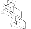
次に本発明の実施形態について説明する。実施形態に示した用水路補修用止水壁部材は、細長船体1に、杭装着筒部2と、底堰板部3と、可動堰板部4を設けたものである。
Next, an embodiment of the present invention will be described. The waterway repair water blocking wall member shown in the embodiment is obtained by providing a
細長船体1は、細幅で全長5〜20m程度の鋼船で、杭装着筒部2は、細長船体1の舷側に適宜間隔で縦設したものである。
The
底堰板部3は、細長船体1の船底全長で下方へ突設したもので、船底に設けた装着板部31と、前記装着板部31に着脱可能に設けた底堰板体32で構成したものである。尚底堰板体32は高さの相違するものを複数用意しておき、補修対象の用水路01の水量(水位)に対応して選択的に使用する。
The bottom
可動堰板部4は、前記細長船体1の船首及び船尾に、用水路01の擁壁02の補修作業を行うことができる空間を確保できるに十分な長さ(前後長)を備えて、基部を回動可能に設けたもので、可動装着板部41と可動堰板体42で構成してなる。可動装着板部41は、細長船体1の船首及び船尾に水密に枢結して回動可能としたものである。
The movable dam plate portion 4 has a length (front / rear length) sufficient to secure a space in the bow and stern of the
可動堰板体42は、前記可動装着板部41に着脱可能に設けたもので、先縁にゴム質体で形成したシール板43を突設し、装着時に船体底堰板部3の前後端部を覆う小シール板44を付設してなるものである。尚可動堰板体42は、前記底堰板体32と同様には高さの相違するものを複数用意しておき、底堰板体32と対応して選択的に装着するものである。また前記のシール板43及び小シール板44は、後述する底堰板体32及び可動堰板体42の下縁が水路底03に食い込む深さ分を、下縁から間隔を空けて設けておく。
The movable
次に前記用水路補修用止水壁部材を使用して用水路補修用仮締切を行う本発明工法について説明する。 Next, the construction method of the present invention in which a temporary closing for repairing a water channel is performed using the water blocking wall member for repairing the water channel will be described.
実施形態として示す用水路補修用仮締切工法は、細長船体1を二艘使用する例を示すが、本発明工法は一艘でもまた多数艘でも使用できるものである。
The temporary closing method for irrigation canal repair shown as an embodiment shows an example in which two
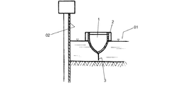
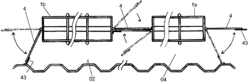
使用する細長船体1a,1bには、予め用水路01の水位に合わせて所定の底堰板体32及び可動堰板体42を装着しておく。この細長船体1a,1bを縦列して用水路01に浮かべ、補修対象の擁壁02と補修工事の空間が確保できる分の距離をとって対向して添わせる(図3)。
A predetermined bottom
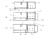
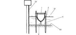
次に当該位置で杭装着筒部2を通して杭5を水路底03に打ち込み、細長船体1a,1bを所定間隔で複数船体縦列させて用水路01内で錨止する(図4)。更に可動堰板部4を回動して所定位置とするもので、具体的には先方細長船体1aの船首の可動堰板部4と、後方細長船体1bの船尾の可動堰板部4は、それぞれ擁壁02に先端のシール板43が当接するようにし、前後細長船体1a,1bの間の可動堰板部4は、互いに重ね合わせて細長船体1a,1bと各可動堰板部4で、補修対象擁壁02を用水路01内において区切るように配置する(図7)。
Next, the
そして前記の区切られた作業空間04となる範囲の用水05をポンプで汲み上げて、細長船体1a,1b内に注水する(図5)。細長船体1a,1bは、その注水量に応じて沈下するので、注水された細長船体1a,1bの重みで底堰板体32及び可動堰板体42の下縁が水路底03に食い込むまで注水する。
And the
細長船体1a,1bが所定位置(底堰板体32及び可動堰板体42で作業空間04が他の部分から遮断される位置)まで沈下したら、作業空間04となる範囲の用水05の全てを用水路01の水流側に排出する(図6)。そうすると作業空間04は、細長船体1a,1b、底堰板体32及び可動堰板体42が止水壁となって仮締切が実現し、露出した矢板鋼板の擁壁02の補修作業が可能となる。
When the
当該区間の擁壁02の補修作業が終了すると、細長船体1a,1bの船体内の用水05を作業空間04に排出し、更に作業空間04を満水にすると、細長船体1a,1bが浮上し、底堰板体32及び可動堰板体42が水路底03から引き抜かれる。更に杭5を引き抜いて細長船体1a,1bの移動を可能として、次の補修工事区間に移動させ、補修工事を続行するものである。
When the repair work of the
このように用水路01に浮かべた細長船体1自体を止水壁として仮締切を実現して、順次用水路の補修工事を行うようにしたものである。
In this way, the temporary hull is realized by using the
尚前記実施形態は、底堰板部3及び可動堰板部4を、装着板部31と底堰板体32並びに可動装着板部41と可動堰板体42で構成し、複数の底堰板体32並びに可動堰板体42から用水路01の水位に合わせて選択装着する例を示したが、底堰板体32並びに可動堰板体42を上下位置調整自在に装着するようにしても良いし、また所定範囲の水位で使用するように着脱構造の底堰板体32並びに可動堰板体42を採用しなくとも良い。
In the embodiment, the bottom
1(1a,1b) 細長船体
2 杭装着筒部
3 底堰板部
31 装着板部
32 底堰板体
4 可動堰板部
41 可動装着板部
42 可動堰板体
43 シール板
44 小シール板
5 杭
01 用水路
02 擁壁
03 水路底
04 作業空間
05 用水
DESCRIPTION OF SYMBOLS 1 (1a, 1b)
Claims (3)
Priority Applications (1)
| Application Number | Priority Date | Filing Date | Title |
|---|---|---|---|
| JP2012239836A JP5956908B2 (en) | 2012-10-31 | 2012-10-31 | Reservoir wall member for irrigation channel repair and temporary closing method for irrigation channel repair |
Applications Claiming Priority (1)
| Application Number | Priority Date | Filing Date | Title |
|---|---|---|---|
| JP2012239836A JP5956908B2 (en) | 2012-10-31 | 2012-10-31 | Reservoir wall member for irrigation channel repair and temporary closing method for irrigation channel repair |
Publications (2)
| Publication Number | Publication Date |
|---|---|
| JP2014088721A true JP2014088721A (en) | 2014-05-15 |
| JP5956908B2 JP5956908B2 (en) | 2016-07-27 |
Family
ID=50790820
Family Applications (1)
| Application Number | Title | Priority Date | Filing Date |
|---|---|---|---|
| JP2012239836A Expired - Fee Related JP5956908B2 (en) | 2012-10-31 | 2012-10-31 | Reservoir wall member for irrigation channel repair and temporary closing method for irrigation channel repair |
Country Status (1)
| Country | Link |
|---|---|
| JP (1) | JP5956908B2 (en) |
Cited By (5)
| Publication number | Priority date | Publication date | Assignee | Title |
|---|---|---|---|---|
| CN108040821A (en) * | 2017-11-06 | 2018-05-18 | 深圳市晟祥知识产权有限公司 | A kind of floating-board type Autoamtic controlled irrigation rig |
| CN110284511A (en) * | 2019-06-21 | 2019-09-27 | 河海大学 | The cofferdam open cutting construction method of the more storehouse rollers of overlength lake Tunnel |
| CN110453706A (en) * | 2019-09-18 | 2019-11-15 | 河南省水利勘测设计研究有限公司 | Underwater canopy cofferdam for channel side slopes reparation |
| CN114277818A (en) * | 2021-12-21 | 2022-04-05 | 中交三公局第三工程有限公司 | Rectangular steel sheet pile cofferdam structure of deepwater bearing platform and construction method thereof |
| CN114753389A (en) * | 2022-03-28 | 2022-07-15 | 南水北调(山东)机电维修有限责任公司 | Self-sinking combined steel cofferdam special for canal lining repair under deepwater condition |
Citations (4)
| Publication number | Priority date | Publication date | Assignee | Title |
|---|---|---|---|---|
| JPS5217320B1 (en) * | 1971-03-15 | 1977-05-14 | ||
| JPS61286417A (en) * | 1985-06-12 | 1986-12-17 | Nippon Kokan Kk <Nkk> | Cofferdam structure |
| JPH06257163A (en) * | 1993-03-04 | 1994-09-13 | Ishikawajima Harima Heavy Ind Co Ltd | Drought barge for shallow water foundation work |
| JP2003129454A (en) * | 2001-10-30 | 2003-05-08 | Ishikawajima Harima Heavy Ind Co Ltd | Floating gate |
-
2012
- 2012-10-31 JP JP2012239836A patent/JP5956908B2/en not_active Expired - Fee Related
Patent Citations (4)
| Publication number | Priority date | Publication date | Assignee | Title |
|---|---|---|---|---|
| JPS5217320B1 (en) * | 1971-03-15 | 1977-05-14 | ||
| JPS61286417A (en) * | 1985-06-12 | 1986-12-17 | Nippon Kokan Kk <Nkk> | Cofferdam structure |
| JPH06257163A (en) * | 1993-03-04 | 1994-09-13 | Ishikawajima Harima Heavy Ind Co Ltd | Drought barge for shallow water foundation work |
| JP2003129454A (en) * | 2001-10-30 | 2003-05-08 | Ishikawajima Harima Heavy Ind Co Ltd | Floating gate |
Cited By (9)
| Publication number | Priority date | Publication date | Assignee | Title |
|---|---|---|---|---|
| CN108040821A (en) * | 2017-11-06 | 2018-05-18 | 深圳市晟祥知识产权有限公司 | A kind of floating-board type Autoamtic controlled irrigation rig |
| CN108040821B (en) * | 2017-11-06 | 2020-07-07 | 李德良 | Floating plate type automatic control irrigation device |
| CN110284511A (en) * | 2019-06-21 | 2019-09-27 | 河海大学 | The cofferdam open cutting construction method of the more storehouse rollers of overlength lake Tunnel |
| CN110453706A (en) * | 2019-09-18 | 2019-11-15 | 河南省水利勘测设计研究有限公司 | Underwater canopy cofferdam for channel side slopes reparation |
| CN110453706B (en) * | 2019-09-18 | 2024-06-04 | 河南省水利勘测设计研究有限公司 | Underwater awning type cofferdam for repairing side slope of channel |
| CN114277818A (en) * | 2021-12-21 | 2022-04-05 | 中交三公局第三工程有限公司 | Rectangular steel sheet pile cofferdam structure of deepwater bearing platform and construction method thereof |
| CN114277818B (en) * | 2021-12-21 | 2023-10-17 | 中交三公局第三工程有限公司 | Rectangular steel sheet pile cofferdam structure of deepwater bearing platform and construction method thereof |
| CN114753389A (en) * | 2022-03-28 | 2022-07-15 | 南水北调(山东)机电维修有限责任公司 | Self-sinking combined steel cofferdam special for canal lining repair under deepwater condition |
| CN114753389B (en) * | 2022-03-28 | 2023-11-28 | 南水北调(山东)机电维修有限责任公司 | Self-sinking type combined steel cofferdam special for repairing canal lining under deepwater condition |
Also Published As
| Publication number | Publication date |
|---|---|
| JP5956908B2 (en) | 2016-07-27 |
Similar Documents
| Publication | Publication Date | Title |
|---|---|---|
| JP5956908B2 (en) | Reservoir wall member for irrigation channel repair and temporary closing method for irrigation channel repair | |
| CN107002376B (en) | Floating gate or island and method for manufacturing same | |
| US20190145072A1 (en) | Sea wall structures, sea walls and methods of manufacture and assembly of the same | |
| CN113931135A (en) | Column cage stone pile supporting cage type flashboard for blocking breach and burst and rapid emergency rescue method | |
| CN201915414U (en) | Spliced steel box coefferdam | |
| JP6501547B2 (en) | Existing bank body repair structure and repair method of existing bank body | |
| CN105887760B (en) | A kind of ecotypic damaged shore protection repairs structure | |
| JP6104138B2 (en) | Rehabilitation of river structures | |
| JP6915844B2 (en) | Work space formation for wall surface repair and work space formation method for wall surface repair | |
| CN212335895U (en) | An improved prefabricated mountain river bank protection structure | |
| CN212200477U (en) | River-blocking weir gate anti-impact sinking well group and connecting structure comprising same | |
| JP2015031093A (en) | Waterproof wall for revetment repair and method for repairing revetment | |
| CN211080123U (en) | Ecological bank slope protection device in river lake | |
| CN116145623A (en) | A construction method for a combined structure of a diversion open channel and a navigable building | |
| JP7212660B2 (en) | Coastal structures that reduce sedimentation and erosion caused by coastal sand transport | |
| Swatek Jr | Cellular cofferdam design and practice | |
| CN109281286B (en) | Construction method of energy dissipation diversion channel in mountainous area | |
| JP5306885B2 (en) | Construction method for underwater structures | |
| CN212129043U (en) | Novel mixed dyke of double sheet pile type | |
| CN114150612A (en) | Construction method suitable for digging small river channel | |
| CN119465867B (en) | Permeable concrete filling structure for river bottom pit and construction method thereof | |
| CN221118571U (en) | Rigid joint for underground diaphragm wall | |
| NZ714385A (en) | Erosion prevention arrangement | |
| JP6322560B2 (en) | Renewal method of existing revetment or quay and revetment or quay structure | |
| CN220284708U (en) | Assembled river levee module |
Legal Events
| Date | Code | Title | Description |
|---|---|---|---|
| A621 | Written request for application examination |
Free format text: JAPANESE INTERMEDIATE CODE: A621 Effective date: 20150918 |
|
| TRDD | Decision of grant or rejection written | ||
| A977 | Report on retrieval |
Free format text: JAPANESE INTERMEDIATE CODE: A971007 Effective date: 20160525 |
|
| A01 | Written decision to grant a patent or to grant a registration (utility model) |
Free format text: JAPANESE INTERMEDIATE CODE: A01 Effective date: 20160531 |
|
| A61 | First payment of annual fees (during grant procedure) |
Free format text: JAPANESE INTERMEDIATE CODE: A61 Effective date: 20160617 |
|
| R150 | Certificate of patent or registration of utility model |
Ref document number: 5956908 Country of ref document: JP Free format text: JAPANESE INTERMEDIATE CODE: R150 |
|
| R250 | Receipt of annual fees |
Free format text: JAPANESE INTERMEDIATE CODE: R250 |
|
| LAPS | Cancellation because of no payment of annual fees |