JP2014040749A - Method for raising building, and building structure - Google Patents
Method for raising building, and building structure Download PDFInfo
- Publication number
- JP2014040749A JP2014040749A JP2012184378A JP2012184378A JP2014040749A JP 2014040749 A JP2014040749 A JP 2014040749A JP 2012184378 A JP2012184378 A JP 2012184378A JP 2012184378 A JP2012184378 A JP 2012184378A JP 2014040749 A JP2014040749 A JP 2014040749A
- Authority
- JP
- Japan
- Prior art keywords
- lifting
- column
- building
- beam member
- raising
- Prior art date
- Legal status (The legal status is an assumption and is not a legal conclusion. Google has not performed a legal analysis and makes no representation as to the accuracy of the status listed.)
- Granted
Links
- 238000000034 method Methods 0.000 title claims abstract description 21
- 230000035515 penetration Effects 0.000 claims abstract description 31
- 230000000149 penetrating effect Effects 0.000 claims abstract description 20
- 229910000831 Steel Inorganic materials 0.000 claims description 27
- 239000010959 steel Substances 0.000 claims description 27
- 238000009434 installation Methods 0.000 claims description 11
- 230000005484 gravity Effects 0.000 claims description 8
- 239000004567 concrete Substances 0.000 description 12
- 230000003014 reinforcing effect Effects 0.000 description 4
- 230000007547 defect Effects 0.000 description 3
- 239000000463 material Substances 0.000 description 3
- 238000010276 construction Methods 0.000 description 2
- 238000003780 insertion Methods 0.000 description 2
- 230000037431 insertion Effects 0.000 description 2
- 239000011150 reinforced concrete Substances 0.000 description 2
- 238000003466 welding Methods 0.000 description 2
- 230000015572 biosynthetic process Effects 0.000 description 1
- 230000006835 compression Effects 0.000 description 1
- 238000007906 compression Methods 0.000 description 1
- 230000007423 decrease Effects 0.000 description 1
- 230000006866 deterioration Effects 0.000 description 1
- 239000000945 filler Substances 0.000 description 1
- 238000012423 maintenance Methods 0.000 description 1
- 230000002093 peripheral effect Effects 0.000 description 1
- 238000003825 pressing Methods 0.000 description 1
- 239000002689 soil Substances 0.000 description 1
Images
Landscapes
- Working Measures On Existing Buildindgs (AREA)
- Foundations (AREA)
Abstract
Description
本発明は、基礎部の上に柱を設置してある建物において、例えば不同沈下等の地盤沈下に伴って揚重装置で該当する柱を上昇させ、前記基礎部と前記柱との間に生じた隙間に、前記柱の軸力を支持させる支持部材を設置する建物嵩上げ方法、及び、その建物嵩上げ方法に使用する建物構造に関する。 The present invention, in a building in which a pillar is installed on a foundation, raises the corresponding pillar with a lifting device in association with ground subsidence such as non-uniform subsidence, and occurs between the foundation and the pillar. The present invention relates to a building raising method in which a support member for supporting the axial force of the pillar is installed in the gap, and a building structure used for the building raising method.
従来、この種の建物嵩上げ技術としては、鉄骨構造の建物を例に挙げて説明すると、まず、建物の建設時に、全ての柱(H形鋼)を対象として、下端部からジャッキ装置(揚重装置の一例)設置高さ相当分の離間距離をあけた位置の両側面に、それぞれ横方向に張り出す状態に揚重用梁部材(H形鋼)を溶接によって固着しておく。
次に、建設後の建物荷重によって地盤沈下が生じると、両揚重用梁部材の下方の地盤上にそれぞれジャッキ装置をセットし、それらのジャッキ装置の揚重力を揚重用梁部材に作用させ、揚重用梁部材を介して柱を上昇させる。続いて、フィラープレート等の支持部材を、基礎部と柱との間に挟んだ後、ジャッキ装置の揚重力を開放して基礎部に対して支持部材を介して柱を固定することで建物の嵩上げを行う(例えば、特許文献1、特に図1参照)方法があった。
Conventionally, as an example of this type of building raising technique, a steel structure building will be described as an example. First, at the time of construction of a building, all columns (H-shaped steel) are targeted at a jack device (lifting). An example of an apparatus) A beam member for lifting (H-shaped steel) is fixed by welding on both side surfaces at positions spaced apart by a distance corresponding to the installation height so as to project laterally.
Next, when ground subsidence occurs due to the building load after construction, jack devices are set on the ground below the lifting beam members, and the lifting gravity of these jack devices is applied to the lifting beam members. The column is raised through the heavy beam member. Subsequently, after sandwiching a support member such as a filler plate between the foundation part and the pillar, the lifting force of the jack device is released and the pillar is fixed to the foundation part via the support member. There has been a method of raising the height (for example, see
上述した従来の建物嵩上げ技術によれば、前記揚重用梁部材を、全ての柱の両側面に固着しておく必要があるから、その手間と、材料コストとが嵩む問題点がある。
また、揚重用梁部材は、嵩上げ操作を実施しない時でも、柱の両側面に固着されたままになっているので、柱周りの空間は揚重用梁部材によって占用され、自由に使用できる床面積が少なくなる問題点もある。
According to the above-described conventional building raising technique, it is necessary to fix the lifting beam members on both side surfaces of all the pillars. Therefore, there is a problem that the labor and the material cost increase.
In addition, since the lifting beam member remains fixed to both sides of the column even when the lifting operation is not performed, the space around the column is occupied by the lifting beam member and can be used freely. There is also a problem that decreases.
従って、本発明の目的は、上記問題点を解消し、嵩上げを行わない通常時には床面積を広く使用でき、且つ、手間を掛けずに経済的に建物嵩上げを実施できる建物嵩上げ技術を提供するところにある。 Accordingly, an object of the present invention is to provide a building raising technique that can solve the above-mentioned problems, can use a wide floor area during normal times without raising the floor, and can economically carry out the building raising without taking time and effort. It is in.
本発明の第1の特徴構成は、基礎部の上に柱を設置してある建物において、例えば不同沈下等の地盤沈下に伴って揚重装置で該当する柱を上昇させ、前記基礎部と前記柱との間に生じた隙間に、前記柱の軸力を支持させる支持部材を設置する建物嵩上げ方法であって、前記揚重装置の揚重力を前記柱に伝達する揚重用梁部材が横方向に貫通自在な梁貫通部を、前記柱に形成しておき、前記梁貫通部に前記揚重用梁部材を貫通させて、前記揚重用梁部材に前記揚重装置の揚重力を作用させ、前記揚重用梁部材を介して前記柱を上昇させるところにある。 In a first characteristic configuration of the present invention, in a building in which a column is installed on a foundation, for example, the corresponding column is lifted by a lifting device along with ground subsidence such as non-uniform subsidence, A building raising method in which a support member for supporting the axial force of the column is installed in a gap generated between the column and a lifting beam member for transmitting the lifting gravity of the lifting device to the column in a lateral direction A beam penetrating portion that is freely penetrable to the column, the lifting beam member is allowed to pass through the beam penetrating portion, and the lifting force of the lifting device is applied to the lifting beam member, The column is raised through the lifting beam member.
本発明の第1の特徴構成によれば、建物の嵩上げ作業を実施する時には、柱の梁貫通部に貫通させた揚重用梁部材を使用して建物の嵩上げ作業を実施できると共に、嵩上げ作業を実施しない時には、柱の梁貫通部から揚重用梁部材を撤去して、柱周りを広く使用することができる。 According to the first characteristic configuration of the present invention, when carrying out the raising work of the building, the lifting work of the building can be carried out using the lifting beam member penetrated through the beam penetration portion of the column, and the raising work is performed. When not implemented, the beam member for lifting can be removed from the beam penetration portion of the column, and the periphery of the column can be widely used.
また、揚重用梁部材は、どの柱にも貫通させて使用できるから、従来のように、全ての柱に揚重用梁部材を予め固着しておく必要が無くなり、固着手間を掛けずに、且つ、材料コストの削減を図ることができる。 In addition, since the lifting beam member can be used by penetrating any column, it is not necessary to previously fix the lifting beam member to all the columns as in the prior art. The material cost can be reduced.
以上の結果、嵩上げを行わない通常時には床面積を広く使用でき、且つ、手間を掛けずに経済的に建物嵩上げを実施できる。
また、柱の外周部を、化粧パネルで覆うような場合、柱の梁貫通孔の軸芯上に位置する化粧パネル部分に、同様の梁貫通孔を形成しておけば、化粧パネルを取り外したり壊さずに嵩上げ作業を実施することができ、柱周りの良好な意匠性を確保できる。特に、化粧パネルの梁貫通孔に、着脱自在な蓋部材を設けておけば、通常時の美観性を向上させることができる。
As a result of the above, the floor area can be widely used in the normal time when the building is not raised, and the building can be raised more economically without trouble.
Also, when the outer periphery of the column is covered with a decorative panel, if the same beam through hole is formed in the decorative panel part located on the axis of the beam through hole of the column, the decorative panel can be removed. The raising work can be carried out without breaking, and a good design around the column can be secured. In particular, if a detachable lid member is provided in the beam through hole of the decorative panel, the aesthetics at normal times can be improved.
本発明の第2の特徴構成は、前記柱は、H形鋼で構成し、前記梁貫通部は、前記柱のウェブに形成するところにある。 According to a second characteristic configuration of the present invention, the column is formed of an H-shaped steel, and the beam penetration portion is formed in a web of the column.
本発明の第2の特徴構成によれば、梁貫通部の形成に伴う断面欠損の影響を、より少なくすることができる。
即ち、H形鋼のフランジに梁貫通部を設けるのに比較して、断面欠損に伴う断面性能(断面二次モーメントや断面係数等)の低下をより少なくすることができ、強度の低下を最小限に抑えることができる。
According to the second characteristic configuration of the present invention, it is possible to further reduce the influence of the cross-sectional defect accompanying the formation of the beam penetration portion.
In other words, compared to the H-shaped steel flange with a beam penetration, the reduction in cross-sectional performance (cross-sectional secondary moment, section modulus, etc.) due to cross-sectional defects can be reduced and the reduction in strength is minimized. To the limit.
本発明の第3の特徴構成は、前記揚重用梁部材からの揚重力を面で支持する面支持部を、前記梁貫通部に前記揚重用梁部材を挿入する前に、前記柱に取り付けておくところにある。 According to a third feature of the present invention, a surface support portion that supports lifting gravity from the lifting beam member by a surface is attached to the column before the lifting beam member is inserted into the beam penetration portion. There is a place to leave.
本発明の第3の特徴構成によれば、揚重用梁部材からの揚重力を、面支持部を介して柱に無理なく伝達することができる。その結果、揚重に伴う支圧力が梁貫通部の上縁のウェブに直接作用することによる圧縮座屈を防止できる。また、揚重装置の駆動に伴って、柱から作用する反力も、前記面支持部を介して揚重用梁部材に面で作用するから、揚重用梁部材の一点に応力集中が起こるのを緩和でき、円滑に嵩上げ作業を進行させることができる。 According to the third characteristic configuration of the present invention, the lifting gravity from the lifting beam member can be transmitted to the column without difficulty through the surface support portion. As a result, it is possible to prevent compression buckling due to the support pressure accompanying lifting directly acting on the web at the upper edge of the beam penetration portion. In addition, the reaction force acting from the column with the driving of the lifting device also acts on the lifting beam member via the surface support portion, so that stress concentration at one point of the lifting beam member is mitigated. It is possible to carry out the raising work smoothly.
本発明の第4の特徴構成は、前記揚重装置による前記揚重用梁部材を介した前記柱の上昇操作状態において、前記梁貫通部と前記揚重用梁部材との相対姿勢の維持を図る姿勢維持手段を、前記梁貫通部と前記揚重用梁部材との間、又は、何れか一方に設けるところにある。 A fourth characteristic configuration of the present invention is an attitude for maintaining a relative attitude between the beam penetrating portion and the lifting beam member in a lifting operation state of the column via the lifting beam member by the lifting device. The maintaining means is provided between the beam penetrating portion and the beam member for lifting or any one of them.
本発明の第4の特徴構成によれば、梁貫通部に挿入した揚重用梁部材の両端側を、それぞれ揚重装置によって揚重する際に、バランスが多少くずれても、姿勢維持手段によって梁貫通部での揚重用梁部材が傾斜したりズレたりするのを防止でき、安定した状態で嵩上げ作業を実施することができる。 According to the fourth characteristic configuration of the present invention, even when both ends of the lifting beam member inserted into the beam penetrating portion are lifted by the lifting device, the beam is maintained by the posture maintaining means even if the balance is slightly lost. It is possible to prevent the lifting beam member in the penetrating portion from being inclined or shifted, and the lifting work can be performed in a stable state.
本発明の第5の特徴構成は、請求項1〜4の何れか一項に記載の建物嵩上げ方法に使用する建物構造であって、前記柱に、前記揚重用梁部材を横方向に貫通自在な梁貫通部が設けてあり、前記梁貫通部に貫通させた前記揚重用梁部材の両端部の下方側に位置する建物部に、前記揚重装置を設置自在な揚重装置設置予定部がそれぞれ設けてあるところにある。 5th characteristic structure of this invention is a building structure used for the building raising method as described in any one of Claims 1-4, Comprising: The said beam member for lifting can be penetrated in the horizontal direction in the said pillar. There is a lifting device installation scheduled portion where the lifting device can be freely installed in a building portion located below both ends of the lifting beam member penetrated through the beam penetration portion. It is in the place where each is provided.
本発明の第5の特徴構成によれば、地盤沈下が生じた場合、梁貫通部に揚重用梁部材を貫通させて、建物部の揚重装置設置予定部上にそれぞれ揚重装置を設置し、揚重用梁部材を揚重するだけで、簡単に柱を上昇させることができ、上昇した柱と基礎部との間に支持部材を設置して揚重解除すれば、支持部材の高さ分の建物の嵩上げを簡単に行うことができる。
また、嵩上げ作業を実施しない時には、柱の梁貫通部から揚重用梁部材を撤去して、柱周りを広く使用することができる。
また、揚重用梁部材は、どの柱にも貫通させて使用できるから、従来のように、全ての柱に揚重用梁部材を予め固着しておく必要が無くなり、固着手間を掛けずに、且つ、材料コストの削減を図ることができる。
以上の結果、嵩上げを行わない通常時には床面積を広く使用でき、且つ、手間を掛けずに経済的に建物嵩上げを実施できる。
また、柱の外周部を、化粧パネルで覆うような場合、柱の梁貫通孔の軸芯上に位置する化粧パネル部分に、同様の梁貫通孔を形成しておけば、化粧パネルを取り外したり壊さずに嵩上げ作業を実施することができ、柱周りの良好な意匠性を確保できる。特に、化粧パネルの梁貫通孔に、着脱自在な蓋部材を設けておけば、通常時の美観性を向上させることができる。
According to the fifth characteristic configuration of the present invention, when ground subsidence occurs, the lifting beam is installed on the lifting device installation planned portion of the building by passing the lifting beam member through the beam penetration portion. By simply lifting the beam member for lifting, the column can be lifted up easily. If a support member is installed between the raised column and the foundation and lift is released, the height of the support member can be increased. The building can be easily raised.
Further, when the lifting work is not performed, the lifting beam member can be removed from the beam penetration portion of the column, and the periphery of the column can be widely used.
In addition, since the lifting beam member can be used by penetrating any column, it is not necessary to previously fix the lifting beam member to all the columns as in the prior art. The material cost can be reduced.
As a result of the above, the floor area can be widely used in the normal time when the building is not raised, and the building can be raised more economically without trouble.
Also, when the outer periphery of the column is covered with a decorative panel, if the same beam through hole is formed in the decorative panel part located on the axis of the beam through hole of the column, the decorative panel can be removed. The raising work can be carried out without breaking, and a good design around the column can be secured. In particular, if a detachable lid member is provided in the beam through hole of the decorative panel, the aesthetics at normal times can be improved.
以下に本発明の実施の形態を図面に基づいて説明する。 Embodiments of the present invention will be described below with reference to the drawings.
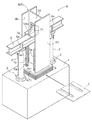
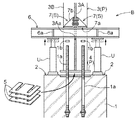
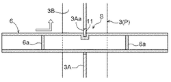
図1は、嵩上げの対象となる鉄骨造の建物Bの要部を示すもので、この建物Bは、基礎コンクリート(基礎部の一例)1の上に立設された柱Pと、図には示さないが、間隔をあけて隣接する柱Pにわたって設置された梁とを備えて構成されている。 FIG. 1 shows a main part of a steel building B to be raised, and this building B is composed of a pillar P standing on a foundation concrete (an example of a foundation) 1 and a figure. Although not shown, it is configured to include a beam installed across an adjacent column P with a space therebetween.
基礎コンクリート1には、複数のアンカーボルト1aが埋設してあり、このアンカーボルト1aと固定ナット1bとで、柱Pの下端部が基礎コンクリート1上に固定されている。
また、基礎コンクリート1における柱Pの立設位置の両側方には、基礎コンクリート1に反力を確保して柱Pを揚重自在なジャッキ装置(揚重装置の一例)Uの設置予定部(揚重装置設置予定部の一例)2がそれぞれ確保されている。
A plurality of
In addition, on both sides of the standing position of the pillar P in the
柱Pは、H形鋼からなる柱本体3の下端部に、矩形形状のベースプレート4を一体に備えて構成してある。
ベースプレート4には、上述の各アンカーボルト1aを挿通自在な挿通部4aがそれぞれ形成されており、この挿通部4aにアンカーボルト1aが貫通する状態に柱Pは配置され、貫通したアンカーボルト1aに固定ナット1bを螺合させて締め付けることで、基礎コンクリート1に柱Pが固定してある。
尚、地盤の不同沈下が発生した場合、該当する部分の柱Pは沈下前の高さに戻すために嵩上げが実施されるが、その嵩上げに伴って、後述する支持高さ調整用支持板(支持部材の一例)5が、基礎コンクリート1とベースプレート4との間に介在される。
The column P is configured by integrally including a
The
In addition, when uneven subsidence of the ground occurs, the column P of the corresponding portion is raised to return to the height before the subsidence, but with the raising, a support height adjustment support plate (described later) An example of a support member 5) is interposed between the
柱本体3は、ウェブ3Aと、一対のフランジ3Bとを備えて構成してある。
平面視において柱本体3のウェブ3Aの表裏面が対向する方向に、上述のジャッキ装置Uの設置予定部2が設けられている。
The column
In the plan view, the above-described jack device U installation planned
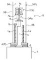
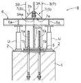
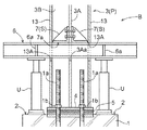
ウェブ3Aには、図2、図3に示すように、柱本体3より小断面のH形鋼で構成された揚重用梁部材6をそれの長手方向に沿って貫通自在な梁貫通部3Aaが形成してある。
As shown in FIGS. 2 and 3, the
この梁貫通部3Aaは、揚重用梁部材6の横断面形状に対応させた矩形形状に設定してあり、高さ位置は、前記設置予定部2上に設置されたジャッキ装置Uの収縮状態での高さ寸法より若干上に位置するように設定してある。梁貫通部3Aaに揚重用梁部材6を挿入して、ジャッキ装置Uで揚重用梁部材6を持ち上げることで、柱Pを持ち上げることができる。
尚、梁貫通部3Aaの設置高さに関しては、柱Pの反曲点、又は、その近傍に設けておけば、断面欠損による断面性能の低下を最小限に抑えることができる。
This beam penetration part 3Aa is set to a rectangular shape corresponding to the cross-sectional shape of the
In addition, regarding the installation height of the beam penetration part 3Aa, if it is provided at the inflection point of the column P or in the vicinity thereof, the deterioration of the cross-sectional performance due to the cross-sectional defect can be minimized.
また、ウェブ3Aにおける梁貫通部3Aaの直上には、図3に示すように、ウェブ3Aを表裏から挟持する一対のアングル部材(面支持部の一例)7を着脱自在なアングル取付部8が設けられている。本実施形態においては、アングル取付部8は、複数のボルト貫通孔で構成されている。
建物Bの通常の状態においては、アングル取付部8には、アングル部材7は取り付けてなくてもよい。
In addition, as shown in FIG. 3, a pair of angle members (an example of a surface support portion) 7 for holding the
In the normal state of the building B, the
また、柱Pを嵩上げ操作する際には、アングル部材7を、横断面形状が「L」字形状となる姿勢で、且つ、アングルの下面部7aが、梁貫通部3Aaの上縁部と同じ高さとなるように、予め、アングル取付部8に取り付けておく。
このようにアングル部材7をアングル取付部8に取り付けることで、前記梁貫通部3Aaに挿通させた揚重用梁部材6をジャッキ装置Uで持ち上げる際、アングル部材7の下面部7aの広い範囲で揚重用梁部材6の上面を受け止めることができると共に、揚重用梁部材6の姿勢を、水平に近い状態に保ち易くなる(図4〜6参照)。
よって、柱Pの嵩上げ操作に伴って、梁貫通部3Aaと揚重用梁部材6との相対姿勢の維持を、アングル部材7によって図ることができる。
アングル部材7は、当該発明に係る面支持部の一例であると同時に、姿勢維持手段Sの一例でもある。
Further, when raising the column P, the
By attaching the
Accordingly, the
The
因みに、前記アングル部材7と、揚重用梁部材6には、それぞれ大きな外力が作用する部分には補強リブ7b,6aが設けてある(図1参照)。具体的には、アングル部材7の場合は、長手方向の中央部に縦壁状の補強リブ7bが設けてあり、揚重用梁部材6の場合は、ジャッキ装置Uの揚重力を受ける部分に、補強リブ6aが設けてある。
Incidentally, the
建物Bの多数の柱Pの内、不同沈下によって沈下が発生した柱Pに対しては、嵩上げが実施され、もとの高さに戻す作業が実施される。
建物嵩上げ方法の手順について、次に説明する。
Of the large number of pillars P of the building B, the pillars P that have undergone subsidence due to non-uniform subsidence are raised and restored to their original height.
Next, the procedure of the building raising method will be described.
[1]該当する柱Pのアングル取付部8に、ウェブ3Aを挟持する状態に一対のアングル部材7を取り付ける(図3参照)。
[2]梁貫通部3Aaに、揚重用梁部材6を挿通する。揚重用梁部材6の長手方向中央部が柱本体3のウェブ3Aの位置に合うようにセットする(図4参照)。
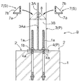
[3]揚重用梁部材6の両端部の下方に位置する両設置予定部2にジャッキ装置Uをそれぞれ設置する(図4参照)。
[4]基礎コンクリート1のアンカーボルト1aから固定ナット1bを取り外す。
[5]両ジャッキ装置Uによる揚重を行う(図5参照)。
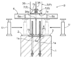
[6]揚重によって基礎コンクリート1とベースプレート4との間にできた隙間に、所定高さ分の支持高さ調整用支持板5を挿入する(図5参照)。
[7]ジャッキ装置Uによる揚重を解除し、支持高さ調整用支持板5の上にベースプレート4を載置させた状態で、アンカーボルト1aに固定ナット1bを取り付けて、柱Pを基礎コンクリート1に固定する(図6参照)。
[8]ジャッキ装置U、揚重用梁部材6、アングル部材7等の揚重アイテムを撤去する。
[1] A pair of
[2] The
[3] The jack devices U are respectively installed on the two scheduled
[4] Remove the fixing
[5] Lifting is performed by both jack apparatuses U (see FIG. 5).
[6] A support height adjusting
[7] Lifting by the jack unit U is released, and the
[8] Lifting items such as the jack device U, the
本実施形態で説明した建物嵩上げ技術によれば、建物の嵩上げを行わない通常時には、柱Pの周りを占用することがないから、柱周りを広く使用できながら、建物の嵩上げ作業を実施する時だけ、該当する柱Pに上述の揚重アイテムをセットして、簡単且つ効率的に嵩上げ作業を実施することができる。
また、揚重アイテムは、どの柱Pにも使用できるから、兼用化によって固定費用を低減でき、経済的に建物嵩上げを実施できる。
しかも、梁貫通部3Aaは、柱Pのウェブ3Aに設けてあるから、構造が簡単で加工性に富んでおり、安価に提供できることに加えて、フランジ3Bに設けるのに比べて強度の低下を抑制することができる。
更には、面支持部や姿勢維持手段となるアングル部材7を設けてあることで、嵩上げ作業を、無理なく安定した状態で進めることができる。
According to the building raising technique described in the present embodiment, when the building is not raised normally, the surroundings of the pillar P are not occupied, so when the building raising work is performed while the pillars can be widely used. Only the above-mentioned lifting item can be set on the corresponding pillar P, and the raising work can be carried out easily and efficiently.
In addition, since the lifting item can be used for any pillar P, it is possible to reduce the fixing cost by sharing the use of the lifting item and economically raise the building.
Moreover, since the beam penetration portion 3Aa is provided in the
Furthermore, since the
〔別実施形態〕
以下に他の実施の形態を説明する。
[Another embodiment]
Other embodiments will be described below.
〈1〉 当該発明技術の対象となる建物は、先の実施形態で説明した鉄骨構造に限るものではなく、例えば、鉄筋コンクリート造や、鉄骨鉄筋コンクリート造や、木造等であってもよい。また、建物用途は、様々なものが該当し、例えば、倉庫や、体育館や、商業施設や、橋梁等であってもよい。従って、柱Pや基礎部1の構成は、先の実施形態で説明したものに限定されるものではない。
例えば、建物が鉄骨構造の場合、柱Pは、H形鋼に限るものではなく、例えば、I形鋼やC形鋼や角形鋼管や鋼管や他の形鋼等の単独、又は、組合せで構成してあってもよい。
また、基礎部1は、先の実施形態で説明した独立フーチングの基礎コンクリートに限るものではなく、例えば、基礎梁や、土間であってもよく、要するに、柱Pの荷重を受けて地盤に伝達する構成であればよく、それらを含めて基礎部1という。
<1> The building that is the subject of the present invention is not limited to the steel structure described in the previous embodiment, and may be, for example, a reinforced concrete structure, a steel reinforced concrete structure, a wooden structure, or the like. In addition, various buildings are applicable, and may be, for example, a warehouse, a gymnasium, a commercial facility, a bridge, or the like. Therefore, the structure of the pillar P and the
For example, when the building has a steel structure, the column P is not limited to the H-shaped steel, and is composed of, for example, an I-shaped steel, a C-shaped steel, a square steel pipe, a steel pipe, and other shaped steels alone or in combination. It may be.
The
〈2〉 前記揚重用梁部材6は、先の実施形態で説明したH形鋼に限るものではなく、例えば、I形鋼やC形鋼や角形鋼管や鋼管や他の形鋼等で構成してあってもよい。
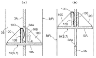
また、前記面支持部7は、先の実施形態で説明したアングル部材に限るものではなく、例えば、溝形鋼や角形鋼管等で構成してあってもよい。また、図7に示すように、ウェブ3Aにおける梁貫通部3Aaの上縁部に嵌合できるように形成された面支持部材10で構成してあってもよい。
面支持部材10は、揚重用梁部材6の上面と当接自在な長方形の平板部10Aと、平板部10Aの長手方向の中間部に隙間kをあけて立設された一対の縦板部10Bと、平板部10Aと縦板部10Bとにわたって設けられた一対の補強リブ10Cと、一対の縦板部10B間に嵌入するウェブ3Aと、一方の縦板部10Bとの間で、双方に押圧力を作用させて抜け止めを図る板バネ部材10Dとを設けて構成してある。
この面支持部材10は、前記板バネ部材10Dを、一方の縦板部10Bに係合させた状態で、梁貫通部3Aaに位置させて、前記隙間kに、ウェブ3Aの梁貫通部3Aaの上縁部が嵌入するように上昇させると、前記板バネ部材10Dの弾性復元力の作用で、梁貫通部3Aaの上縁部に抜け止め状態で設置することができる。先のアングル部材に比べて、着脱作業の効率化を図ることができる。尚、面支持部材10は、本発明に係る「面支持部」の機能と「姿勢維持手段」の機能とを併せもっている。
<2> The
Moreover, the said
The surface support member 10 includes a rectangular
The surface support member 10 is positioned in the beam penetration portion 3Aa in a state where the
〈3〉 前記面支持部7や、前記姿勢維持手段Sは、先の実施形態で説明したように、揚重用梁部材6とは別体で構成してあるものに限るものではなく、揚重用梁部材6と一体的に設けてあってもよい。
<3> The
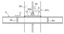
〈4〉 前記姿勢維持手段Sは、先の実施形態で説明したアングル部材7や面支持部材10に限るものではなく、例えば、図8、図9に示すように、揚重用梁部材6の中央部上面に、柱Pのウェブ3Aに外嵌する状態で一体に形成された凹部11を備えて構成してあってもよい。図8の実施形態は、凹部11を形成するのに、一対の山形鋼12を、隙間をあけて揚重用梁部材6に溶接等で固着してある。図9の実施形態は、揚重用梁部材6の上面部の中央部を溝状に窪ませて、凹部11を構成してある。
<4> The posture maintaining means S is not limited to the
〈5〉 前記揚重装置Uは、先の実施形態で説明したように揚重用梁部材6を押し上げるように構成された装置に限るものではなく、例えば、揚重用梁部材6を引き上げるように構成された装置であってもよい。
<5> The lifting device U is not limited to a device configured to push up the
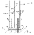
〈6〉 柱Pの外周部に、図10に示すような、化粧板13を配置して囲う場合には、柱Pの梁貫通部3Aaの同一軸芯上に位置する化粧板部分にも、揚重用梁部材6を挿通操作自在な梁貫通部13Aを設けておけば、嵩上げ作業時に、化粧板13を取り去らずに揚重用梁部材6を挿通させて設置でき、効率的に嵩上げ作業を実施できる。
また、梁貫通部13Aに、図11に示すように、開閉操作自在な蓋部材13Bを設けておけば、嵩上げ作業を行わない時の柱P周りの美観性の向上を図ることができる。
<6> When the
In addition, if the
尚、上述のように、図面との対照を便利にするために符号を記したが、該記入により本発明は添付図面の構成に限定されるものではない。また、本発明の要旨を逸脱しない範囲において、種々なる態様で実施し得ることは勿論である。 In addition, as mentioned above, although the code | symbol was written in order to make contrast with drawing convenient, this invention is not limited to the structure of an accompanying drawing by this entry. In addition, it goes without saying that the present invention can be carried out in various modes without departing from the gist of the present invention.
1 基礎コンクリート(基礎部の一例)
2 設置予定部(揚重装置設置予定部の一例)
3A ウェブ
3Aa 梁貫通部
5 支持高さ調整用支持板(支持部材の一例)
6 揚重用梁部材
7 アングル部材(面支持部の一例)
B 建物
P 柱
S 姿勢維持手段
U ジャッキ装置(揚重装置の一例)
1 foundation concrete (example of foundation part)
2 Installation planned part (an example of a lifting equipment installation planned part)
3A Web 3Aa
6 Beam member for lifting 7 Angle member (example of surface support part)
B Building P Column S Posture maintenance means U Jacking device (an example of a lifting device)
Claims (5)
前記揚重装置の揚重力を前記柱に伝達する揚重用梁部材が横方向に貫通自在な梁貫通部を、前記柱に形成しておき、
前記梁貫通部に前記揚重用梁部材を貫通させて、前記揚重用梁部材に前記揚重装置の揚重力を作用させ、前記揚重用梁部材を介して前記柱を上昇させる建物嵩上げ方法。 In a building where a column is installed on the foundation, the column is lifted by a lifting device as the ground sinks, and the axial force of the column is applied to the gap generated between the foundation and the column. A building raising method for installing a supporting member to be supported,
A beam penetrating portion in which a lifting beam member that transmits lifting gravity of the lifting device to the column can be penetrated in a lateral direction is formed in the column,
A building raising method in which the beam member for lifting is passed through the beam penetrating part, the lifting gravity of the lifting device is applied to the beam member for lifting, and the column is raised via the beam member for lifting.
前記梁貫通部は、前記柱のウェブに形成する請求項1に記載の建物嵩上げ方法。 The column is made of H-section steel,
The method of raising a building according to claim 1, wherein the beam penetration portion is formed on a web of the pillar.
前記柱に、前記揚重用梁部材を横方向に貫通自在な梁貫通部が設けてあり、前記梁貫通部に貫通させた前記揚重用梁部材の両端部の下方側に位置する建物部に、前記揚重装置を設置自在な揚重装置設置予定部がそれぞれ設けてある建物構造。 A building structure used in the building raising method according to any one of claims 1 to 4,
In the pillar, a beam penetrating portion that is capable of penetrating the lifting beam member in a lateral direction is provided, and a building portion that is positioned below both ends of the lifting beam member that is penetrated through the beam penetrating portion, A building structure in which a lifting device installation planned section where the lifting device can be freely installed is provided.
Priority Applications (1)
| Application Number | Priority Date | Filing Date | Title |
|---|---|---|---|
| JP2012184378A JP6057059B2 (en) | 2012-08-23 | 2012-08-23 | Building raising method and building structure |
Applications Claiming Priority (1)
| Application Number | Priority Date | Filing Date | Title |
|---|---|---|---|
| JP2012184378A JP6057059B2 (en) | 2012-08-23 | 2012-08-23 | Building raising method and building structure |
Publications (2)
| Publication Number | Publication Date |
|---|---|
| JP2014040749A true JP2014040749A (en) | 2014-03-06 |
| JP6057059B2 JP6057059B2 (en) | 2017-01-11 |
Family
ID=50393193
Family Applications (1)
| Application Number | Title | Priority Date | Filing Date |
|---|---|---|---|
| JP2012184378A Active JP6057059B2 (en) | 2012-08-23 | 2012-08-23 | Building raising method and building structure |
Country Status (1)
| Country | Link |
|---|---|
| JP (1) | JP6057059B2 (en) |
Cited By (6)
| Publication number | Priority date | Publication date | Assignee | Title |
|---|---|---|---|---|
| JP2018040210A (en) * | 2016-09-09 | 2018-03-15 | 株式会社フジタ | Building support structure and method of correcting uneven settlement of buildings |
| JP2019039221A (en) * | 2017-08-25 | 2019-03-14 | 株式会社竹中工務店 | Jack up method |
| CN111335671A (en) * | 2020-03-31 | 2020-06-26 | 南京地下空间高技术产业研究院有限公司 | Deviation rectifying reinforcing mechanism based on house inclination |
| JP2021004549A (en) * | 2020-10-12 | 2021-01-14 | 株式会社フジタ | Support structure of building and correction method of uneven settlement of building |
| KR102300810B1 (en) * | 2020-12-24 | 2021-09-09 | 정명훈 | Apparatus for Lifting Structure and Method for Lifting Structure Using the Apparatus |
| JP2022174561A (en) * | 2021-05-11 | 2022-11-24 | 株式会社竹中工務店 | Column base structure and building |
Families Citing this family (1)
| Publication number | Priority date | Publication date | Assignee | Title |
|---|---|---|---|---|
| CN111608175B (en) * | 2020-06-12 | 2021-07-16 | 湖南城市学院 | A kind of reinforcement pile for building bridge |
Citations (7)
| Publication number | Priority date | Publication date | Assignee | Title |
|---|---|---|---|---|
| JPH02252831A (en) * | 1989-03-28 | 1990-10-11 | Taisei Corp | Pre-fabricated cruciform beam construction method |
| JPH0340403U (en) * | 1989-08-31 | 1991-04-18 | ||
| JPH08189054A (en) * | 1995-01-09 | 1996-07-23 | Shimizu Corp | Structure for differential settlement |
| JPH08232284A (en) * | 1995-02-28 | 1996-09-10 | Seko Komuten:Kk | Method for restoring unevenly settled building and lift member for use in restoration |
| JPH09184301A (en) * | 1995-12-19 | 1997-07-15 | Kazuhiko Kasai | Dimensional matching for bolt joint between beam and pillar in steel framework structure |
| JPH1060936A (en) * | 1996-08-13 | 1998-03-03 | Nikken Sekkei Ltd | Building raising method |
| JPH10195892A (en) * | 1997-01-08 | 1998-07-28 | Hitachi Ltd | Restoration support gantry repair method and apparatus |
-
2012
- 2012-08-23 JP JP2012184378A patent/JP6057059B2/en active Active
Patent Citations (7)
| Publication number | Priority date | Publication date | Assignee | Title |
|---|---|---|---|---|
| JPH02252831A (en) * | 1989-03-28 | 1990-10-11 | Taisei Corp | Pre-fabricated cruciform beam construction method |
| JPH0340403U (en) * | 1989-08-31 | 1991-04-18 | ||
| JPH08189054A (en) * | 1995-01-09 | 1996-07-23 | Shimizu Corp | Structure for differential settlement |
| JPH08232284A (en) * | 1995-02-28 | 1996-09-10 | Seko Komuten:Kk | Method for restoring unevenly settled building and lift member for use in restoration |
| JPH09184301A (en) * | 1995-12-19 | 1997-07-15 | Kazuhiko Kasai | Dimensional matching for bolt joint between beam and pillar in steel framework structure |
| JPH1060936A (en) * | 1996-08-13 | 1998-03-03 | Nikken Sekkei Ltd | Building raising method |
| JPH10195892A (en) * | 1997-01-08 | 1998-07-28 | Hitachi Ltd | Restoration support gantry repair method and apparatus |
Cited By (9)
| Publication number | Priority date | Publication date | Assignee | Title |
|---|---|---|---|---|
| JP2018040210A (en) * | 2016-09-09 | 2018-03-15 | 株式会社フジタ | Building support structure and method of correcting uneven settlement of buildings |
| JP2019039221A (en) * | 2017-08-25 | 2019-03-14 | 株式会社竹中工務店 | Jack up method |
| CN111335671A (en) * | 2020-03-31 | 2020-06-26 | 南京地下空间高技术产业研究院有限公司 | Deviation rectifying reinforcing mechanism based on house inclination |
| CN111335671B (en) * | 2020-03-31 | 2021-08-10 | 南京地下空间高技术产业研究院有限公司 | Deviation rectifying reinforcing mechanism based on house inclination |
| JP2021004549A (en) * | 2020-10-12 | 2021-01-14 | 株式会社フジタ | Support structure of building and correction method of uneven settlement of building |
| JP6991295B2 (en) | 2020-10-12 | 2022-01-12 | 株式会社フジタ | How to fix building support structure and uneven settlement of buildings |
| KR102300810B1 (en) * | 2020-12-24 | 2021-09-09 | 정명훈 | Apparatus for Lifting Structure and Method for Lifting Structure Using the Apparatus |
| JP2022174561A (en) * | 2021-05-11 | 2022-11-24 | 株式会社竹中工務店 | Column base structure and building |
| JP7621177B2 (en) | 2021-05-11 | 2025-01-24 | 株式会社竹中工務店 | Column base structures and buildings |
Also Published As
| Publication number | Publication date |
|---|---|
| JP6057059B2 (en) | 2017-01-11 |
Similar Documents
| Publication | Publication Date | Title |
|---|---|---|
| JP6057059B2 (en) | Building raising method and building structure | |
| US8336267B2 (en) | Construction frame shear lug | |
| US20040231256A1 (en) | Unit building | |
| JP6111922B2 (en) | Column base reinforcement method and apparatus | |
| JP2013044093A (en) | Connection device | |
| JP5221191B2 (en) | Building basic structure and construction method | |
| JP6831714B2 (en) | Tower crane foundation and tower crane | |
| JP5998858B2 (en) | Seismic isolation method for existing buildings | |
| JP2013092006A (en) | New/old building integrated building-movement method | |
| JP6320242B2 (en) | How to install temporary pillars | |
| JP5581632B2 (en) | Structure slide structure, structure slide method, structure construction method | |
| JP2005272116A (en) | Tower crane support device and construction method thereof | |
| JP2018003559A (en) | Column-beam frame repairing method and repaired column-beam frame | |
| JP4654075B2 (en) | Tower crane foundation receiving beam structure | |
| KR20110046079A (en) | Seismic device of the structure and construction method | |
| JP4899210B2 (en) | Sliding bearing and its mounting method and seismic isolation structure | |
| JP2005015159A (en) | Climbing method of climbing crane | |
| JP2016138639A (en) | Seismic isolator exchange structure and seismic isolator exchange method | |
| JP2012167462A (en) | Joint member, joint structure using the same, and steel-frame building | |
| JP5491070B2 (en) | Seismic reinforcement members and earthquake-resistant buildings | |
| JP2003278407A (en) | Temporary restraint jig for seismic isolation device and restraint method | |
| JP2006090078A (en) | Base-isolated building and construction method for the same | |
| JP4249104B2 (en) | Beam reinforcement structure and beam reinforcement method | |
| JP5107014B2 (en) | Seismic isolation material mounting structure | |
| JP2013249708A (en) | Base isolation method for existing building |
Legal Events
| Date | Code | Title | Description |
|---|---|---|---|
| A621 | Written request for application examination |
Free format text: JAPANESE INTERMEDIATE CODE: A621 Effective date: 20150625 |
|
| A977 | Report on retrieval |
Free format text: JAPANESE INTERMEDIATE CODE: A971007 Effective date: 20160422 |
|
| A131 | Notification of reasons for refusal |
Free format text: JAPANESE INTERMEDIATE CODE: A131 Effective date: 20160426 |
|
| A521 | Written amendment |
Free format text: JAPANESE INTERMEDIATE CODE: A523 Effective date: 20160624 |
|
| TRDD | Decision of grant or rejection written | ||
| A01 | Written decision to grant a patent or to grant a registration (utility model) |
Free format text: JAPANESE INTERMEDIATE CODE: A01 Effective date: 20161108 |
|
| A61 | First payment of annual fees (during grant procedure) |
Free format text: JAPANESE INTERMEDIATE CODE: A61 Effective date: 20161122 |
|
| R150 | Certificate of patent or registration of utility model |
Ref document number: 6057059 Country of ref document: JP Free format text: JAPANESE INTERMEDIATE CODE: R150 |