JP2014019938A - Plating device - Google Patents

Plating device Download PDF

Info

Publication number
JP2014019938A
JP2014019938A JP2012162437A JP2012162437A JP2014019938A JP 2014019938 A JP2014019938 A JP 2014019938A JP 2012162437 A JP2012162437 A JP 2012162437A JP 2012162437 A JP2012162437 A JP 2012162437A JP 2014019938 A JP2014019938 A JP 2014019938A
Authority
JP
Japan
Prior art keywords
belt
plating
drive roller
unit
processing unit
Prior art date
Legal status (The legal status is an assumption and is not a legal conclusion. Google has not performed a legal analysis and makes no representation as to the accuracy of the status listed.)
Pending
Application number
JP2012162437A
Other languages
Japanese (ja)
Inventor
Takeshi Demura
剛 出村
Hiroshi Nakajima
弘 中島
Current Assignee (The listed assignees may be inaccurate. Google has not performed a legal analysis and makes no representation or warranty as to the accuracy of the list.)
IDEYA KK
Original Assignee
IDEYA KK
Priority date (The priority date is an assumption and is not a legal conclusion. Google has not performed a legal analysis and makes no representation as to the accuracy of the date listed.)
Filing date
Publication date
Application filed by IDEYA KK filed Critical IDEYA KK
Priority to JP2012162437A priority Critical patent/JP2014019938A/en
Publication of JP2014019938A publication Critical patent/JP2014019938A/en
Pending legal-status Critical Current

Links

Images

Abstract

PROBLEM TO BE SOLVED: To provide a plating device capable of increasing plating treatment efficiency without increasing an occupancy area.SOLUTION: In the plating device 10, a belt-like member 21 is subjected to plating treatment at a plating treatment part 17. In the plating device, a degreasing treatment part 13 of performing treatment to the belt-like member 21 before plating treatment; a first water-washing treatment part 14; a chemical polishing treatment part 15; a second water-washing treatment part 16; a hot water treatment part 18 of performing treatment to the belt-like member 21 after plating treatment; and a drying treatment part are arranged in series. A fifth driving roller part 55 and a sixth driving roller part 56 part provided at the plating treatment part 17 and also carrying the belt-like member 21 spirally to a height direction in a posture at which the surface and back surface of the belt-like member 21 is made into a direction along a vertical direction; and a plating tank 57 provided at the plating treatment part 17 and also performing plating treatment to the belt-like member 21 at a part to which the belt-like member 21 is lineally carried in a part to which the belt-like member 21 is spirally carried.

Description

本発明は、電子部品を形成するフープ材等の帯状部材をめっき処理するめっき装置に関する。   The present invention relates to a plating apparatus for plating a strip-shaped member such as a hoop material that forms an electronic component.

従来、トランジスタ、IC、スイッチ等の電子部品、コネクタ、表面処理が必要な鋼板材料等を大量生産するには、フープ材と呼ばれる帯状部材にめっき処理を施すようにしている。このような帯状部材にめっき処理を行うめっき装置の一例が、特許文献1に記載されている。この特許文献1に記載されためっき装置は、供給リール及び巻取りリールを有している。また、供給リールから巻取りリールに至る帯状部材の搬送経路が設けられており、搬送経路には脱脂処理部、水洗い処理部、化研処理部、めっき処理部、中和処理部、湯洗い処理部、乾燥部等の複数の処理部が、相互に平行に配置されている。また、複数の処理部同士の間には、垂直方向の軸線を中心として回転可能な駆動ローラがそれぞれ設けられている。   Conventionally, in order to mass-produce electronic parts such as transistors, ICs and switches, connectors, and steel plate materials that require surface treatment, a strip member called a hoop material is plated. An example of a plating apparatus that performs plating on such a belt-shaped member is described in Patent Document 1. The plating apparatus described in Patent Document 1 has a supply reel and a take-up reel. In addition, a transport path for the belt-shaped member from the supply reel to the take-up reel is provided. The transport path includes a degreasing section, a water washing section, a chemical treatment section, a plating section, a neutralization section, and a hot water washing process. A plurality of processing units such as a drying unit and a drying unit are arranged in parallel to each other. In addition, drive rollers that are rotatable about a vertical axis are provided between the plurality of processing units.

そして、特許文献1に記載されためっき装置においては、供給リールから繰り出された帯状部材が、駆動ローラに巻き掛けられて搬送方向が反転される。すなわち、帯状部材は、水平方向の平面内で蛇行しながら搬送される過程で、帯状部材が駆動ローラ同士の間で直線状に搬送されるときに、複数の処理部により順次処理が行われて、帯状部材に各処理が施される。この特許文献1に記載されためっき装置によれば、帯状部材が蛇行して搬送されるため、装置全体の専有面積(スペース)を狭くすることができるとされている。   And in the plating apparatus described in patent document 1, the strip | belt-shaped member drawn | fed out from the supply reel is wound around a drive roller, and a conveyance direction is reversed. That is, the belt-like member is conveyed in a meandering manner in a horizontal plane, and when the belt-like member is conveyed linearly between the drive rollers, the processing is sequentially performed by a plurality of processing units. Each treatment is applied to the belt-like member. According to the plating apparatus described in Patent Document 1, since the belt-shaped member is meandered and conveyed, the exclusive area (space) of the entire apparatus can be reduced.

一方、めっき対象物が線材の場合には、特許文献2に記載されるように、めっき槽内に配置された巻回ドラムと、めっき槽の上方に配置された給電ドラムとの間に螺旋状に線材を巻き掛けて、線材を給電ドラムと巻回ドラムとの間を上下方向に移動させながら、めっき処理を行うようにしためっき装置が使用されている。しかしながら、帯状部材をめっき処理する場合には、めっき槽内に配置された巻回ドラムに帯状部材を巻き掛けると、巻回ドラムに接触する帯状部材の内面にはめっき処理を施すことができない。   On the other hand, when the plating object is a wire, as described in Patent Document 2, a spiral shape is formed between a winding drum disposed in the plating tank and a power supply drum disposed above the plating tank. A plating apparatus is used in which a wire is wound around and the plating is performed while moving the wire in the vertical direction between the power supply drum and the winding drum. However, when the strip member is plated, if the strip member is wound around the winding drum disposed in the plating tank, the inner surface of the strip member in contact with the winding drum cannot be plated.

特許第3103753号公報Japanese Patent No. 3103753 特開平5−132797号公報JP-A-5-1332797

上述のように、めっき対象物が帯状部材の場合には、帯状部材を搬送駆動するためのローラやドラムを、めっき槽内に配置することができないので、帯状部材を水平方向に配置させる必要がある。帯状部材を水平方向に搬送移動させながらめっき処理する場合には、めっき装置の専有面積を大きくしなければならない。特に、帯状部材に対するめっき処理効率を高めるために、帯状部材の搬送速度を速くするには、めっき槽等の処理槽の面積を大きくしなければならず、めっき装置の大型化が避けられない。   As described above, when the object to be plated is a belt-like member, the rollers and drums for conveying and driving the belt-like member cannot be placed in the plating tank, so the belt-like member needs to be placed in the horizontal direction. is there. When plating is performed while the belt-shaped member is conveyed and moved in the horizontal direction, the area occupied by the plating apparatus must be increased. In particular, in order to increase the plating processing efficiency for the band-shaped member, in order to increase the transport speed of the band-shaped member, the area of the processing tank such as a plating tank must be increased, and an increase in the size of the plating apparatus is inevitable.

本発明の目的は、専有面積を大きくすることなく、帯状部材に対するめっき処理効率を高めることができるめっき装置を提供することにある。   An object of the present invention is to provide a plating apparatus capable of increasing the plating treatment efficiency for a strip-shaped member without increasing the exclusive area.

本発明は、帯状部材を長手方向に搬送し、めっき処理部で前記帯状部材にめっき処理を施すめっき装置であって、前記帯状部材にめっき処理を施す前に、前記帯状部材に予め定められた処理を施す前処理部と、前記帯状部材にめっき処理を施した後に、前記帯状部材に予め定められた処理を施す後処理部と、前記めっき処理部に間隔をおいて設けられ、かつ、前記帯状部材の表裏面が垂直方向に沿った方向となる姿勢で、前記帯状部材を高さ方向に螺旋状に搬送する搬送機構と、前記めっき処理部に設けられ、かつ、前記帯状部材が螺旋状に搬送されるときの一部分で直線状に搬送される箇所で、かつ、異なる高さで前記帯状部材にめっき処理を複数回施すめっき槽とを有することを特徴とする。   The present invention is a plating apparatus that conveys a belt-like member in the longitudinal direction and performs plating treatment on the belt-like member in a plating treatment section, and is previously set on the belt-like member before plating the belt-like member. A pre-processing unit for performing a treatment, a post-processing unit for performing a predetermined process on the band-shaped member after performing a plating process on the band-shaped member, and a plating processing unit provided at intervals, and The belt-like member is provided in the plating processing section, and the belt-like member is spirally provided in a posture in which the front and back surfaces of the belt-like member are in a direction along the vertical direction. And a plating tank for performing plating treatment on the strip-like member a plurality of times at different heights at a portion where the belt-like member is conveyed linearly.

本発明によれば、帯状部材の表裏面が垂直方向に沿った方向となる姿勢で、帯状部材を高さ方向に螺旋状に搬送するとともに、帯状部材が螺旋状に搬送されるときの一部分で直線状に搬送される。このため、帯状部材が直線状に搬送されるときに高さ方向の異なる箇所で、帯状部材に複数回めっき処理を施すことができる。したがって、めっき装置の専有面積が大きくなることなく、めっき処理効率を高めることができる。   According to the present invention, the belt-shaped member is conveyed in a spiral shape in the height direction in a posture in which the front and back surfaces of the belt-shaped member are in a direction along the vertical direction, and at a part when the belt-shaped member is conveyed spirally. It is conveyed in a straight line. For this reason, when a strip | belt-shaped member is conveyed linearly, in a location where a height direction differs, a strip | belt-shaped member can be plated several times. Therefore, the plating processing efficiency can be increased without increasing the exclusive area of the plating apparatus.

本発明によれば、帯状部材は、高さが異なる複数の駆動ローラに交互に巻き掛けられるため、単位面積当たりにおける帯状部材のめっき処理長を、長くすることができる。   According to the present invention, since the belt-like member is alternately wound around a plurality of driving rollers having different heights, the plating treatment length of the belt-like member per unit area can be increased.

本発明によれば、めっき槽は、第1搬送機構と第2搬送機構との間に設けられているため、水平方向の平面内において、第1駆動機構と第2駆動機構との間の空間を利用することができ、装置全体の専有面積の拡大を一層抑制できる。   According to the present invention, since the plating tank is provided between the first transport mechanism and the second transport mechanism, the space between the first drive mechanism and the second drive mechanism in the horizontal plane. And the expansion of the exclusive area of the entire apparatus can be further suppressed.

本発明におけるめっき装置の全体構成を示す平面図である。It is a top view which shows the whole structure of the plating apparatus in this invention. 本発明のめっき装置において、駆動ローラ部の一例を示す側面図である。In the plating apparatus of this invention, it is a side view which shows an example of a drive roller part. 本発明のめっき装置において、駆動ローラ部に対する帯状部材の巻き掛け状態の一例を示す模式図である。In the plating apparatus of this invention, it is a schematic diagram which shows an example of the winding state of the strip | belt-shaped member with respect to a drive roller part. 本発明のめっき装置に用いられる処理槽の一例を示す斜視図である。It is a perspective view which shows an example of the processing tank used for the plating apparatus of this invention. 本発明のめっき装置に用いられる処理槽の他の例を示す斜視図である。It is a perspective view which shows the other example of the processing tank used for the plating apparatus of this invention. 本発明のめっき装置において、駆動ローラ部の他の例を示す側面図である。In the plating apparatus of this invention, it is a side view which shows the other example of a drive roller part. 本発明のめっき装置において、駆動ローラ部に対する帯状部材の巻き掛け状態の他の例を示す模式図である。In the plating apparatus of this invention, it is a schematic diagram which shows the other example of the winding state of the strip | belt-shaped member with respect to a drive roller part. 本発明のめっき装置において、駆動ローラ部に対する帯状部材の巻き掛け状態の更に他の例を示す模式図である。In the plating apparatus of this invention, it is a schematic diagram which shows the further another example of the winding state of the strip | belt-shaped member with respect to a drive roller part.

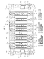
以下、本発明の一実施の形態について、図面を用いて詳細に説明する。図1に示す本発明のめっき装置10は、鋼材、鋼板等を組み合わせて形成された装置本体11を有している。装置本体11は平面形状が略長方形に構成されており、装置本体11は、相互に平行な長辺11b,11c及び相互に平行な短辺11d,11eを有している。装置本体11の上には、供給部12、脱脂処理部13、第1水洗い処理部14、化学研磨処理部15、第2水洗い処理部16、めっき処理部17、湯洗い処理部18、乾燥処理部19、巻取り部20が、帯状部材21の搬送方向(移送方向)に沿って直列に配置されている。本実施形態において、帯状部材21の搬送方向とは、主として水平方向の平面内における搬送方向、または水平方向に沿った搬送方向を意味する。   Hereinafter, an embodiment of the present invention will be described in detail with reference to the drawings. A plating apparatus 10 of the present invention shown in FIG. 1 has an apparatus main body 11 formed by combining steel materials, steel plates and the like. The apparatus main body 11 has a substantially rectangular planar shape, and the apparatus main body 11 has long sides 11b and 11c parallel to each other and short sides 11d and 11e parallel to each other. On the apparatus main body 11, a supply unit 12, a degreasing unit 13, a first water washing unit 14, a chemical polishing unit 15, a second water washing unit 16, a plating unit 17, a hot water washing unit 18, and a drying process. The part 19 and the winding part 20 are arranged in series along the transport direction (transfer direction) of the band-shaped member 21. In the present embodiment, the conveyance direction of the belt-like member 21 mainly means a conveyance direction in a horizontal plane or a conveyance direction along the horizontal direction.

帯状部材21は、金属材料、例えば、ニッケル合金、銅合金、鉄系合金、ステンレス、チタン等の薄板により構成されている。対象となる部品がトランジスタであるときは、帯状部材21には、プレス加工やエッチング加工によって、トランジスタの端子に相当するリード部(図示せず)が予め形成される。また、帯状部材21には、トランジスタ(図示せず)が搭載される。また、対象となる部品によっては、表面に何も加工が施されていないフラットな帯状部材21が用いられる。さらに、対象となる部品には、トランジスタの他、IC、スイッチ等の電子部品、コネクタ、機能材料等も含まれる。なお、以下の説明では、便宜上、帯状部材21の対象となる部品がトランジスタである場合を例として説明する。   The belt-like member 21 is made of a metal material, for example, a thin plate such as a nickel alloy, a copper alloy, an iron-based alloy, stainless steel, or titanium. When the target component is a transistor, lead portions (not shown) corresponding to the terminals of the transistor are formed in advance on the band-like member 21 by pressing or etching. Further, a transistor (not shown) is mounted on the belt-like member 21. Further, depending on the target component, a flat belt-like member 21 whose surface is not subjected to any processing is used. Furthermore, the target components include electronic components such as ICs and switches, connectors, functional materials and the like in addition to transistors. In the following description, for the sake of convenience, the case where the component that is the target of the belt-like member 21 is a transistor will be described as an example.

めっき装置10は、帯状部材21の金属部分、そのうちの主としてリード部に、めっき処理部17によってハンダ、例えば、錫合金、銅めっき、ニッケルめっき、銀めっき、金めっき等を処理する装置である。以下、各機構及び各処理部の構成を説明する。   The plating apparatus 10 is an apparatus for processing solder, for example, tin alloy, copper plating, nickel plating, silver plating, gold plating, or the like, on the metal portion of the band-shaped member 21, mainly the lead portion, by the plating processing portion 17. Hereinafter, the configuration of each mechanism and each processing unit will be described.

供給部12は、装置本体11における一方の短辺11dに沿って設けられている。供給部12は、供給リール22を有しており、供給リール22は電動モータ23により回転される構成となっている。供給リール22の回転軸23aは、水平方向の軸線を中心として回転可能である。帯状部材21は、めっき処理が施される前に供給リール22に巻き付けられている。また、供給部12は、一対のガイドローラ24を有している。一対のガイドローラ24は、水平方向の軸線を中心として回転可能であり、一対のガイドローラ24は可動台25により支持されている。可動台25は、ガイドレール26に沿って水平方向に移動可能に構成されている。また、供給部12は、方向変換ローラ27を有している。方向変換ローラ27は、水平方向の平面内で帯状部材21の搬送方向を変換する機構である。さらに、方向変換ローラ27は、垂直方向の軸線を中心として回転可能に構成されている。一対のガイドローラ24は、帯状部材21の搬送方向において供給リール22よりも下流に配置され、方向変換ローラ27は、帯状部材21の搬送方向において一対のガイドローラ24よりも下流に配置されている。   The supply unit 12 is provided along one short side 11 d of the apparatus main body 11. The supply unit 12 includes a supply reel 22, and the supply reel 22 is configured to be rotated by an electric motor 23. The rotation shaft 23a of the supply reel 22 is rotatable around a horizontal axis. The band-shaped member 21 is wound around the supply reel 22 before the plating process is performed. Further, the supply unit 12 has a pair of guide rollers 24. The pair of guide rollers 24 is rotatable about a horizontal axis, and the pair of guide rollers 24 are supported by a movable base 25. The movable table 25 is configured to be movable in the horizontal direction along the guide rail 26. The supply unit 12 includes a direction changing roller 27. The direction conversion roller 27 is a mechanism that changes the conveyance direction of the belt-like member 21 within a horizontal plane. Further, the direction changing roller 27 is configured to be rotatable about a vertical axis. The pair of guide rollers 24 is disposed downstream of the supply reel 22 in the conveying direction of the band-shaped member 21, and the direction changing roller 27 is disposed downstream of the pair of guide rollers 24 in the conveying direction of the band-shaped member 21. .

脱脂処理部13は、帯状部材21の搬送方向で供給部12よりも下流に設けられている。また、脱脂処理部13は、装置本体11上において、供給部12よりも短辺11dから離れた箇所に設けられている。脱脂処理部13は、第1搬送機構としての第1駆動ローラ部28、及び第2搬送機構としての第2駆動ローラ部29を有している。第1駆動ローラ部28と第2駆動ローラ部29とは、短辺11dに沿った方向で所定間隔をおいて配置されている。第1駆動ローラ部28は、長辺11b側に設けられ、第2駆動ローラ部29は長辺11c側に設けられている。第1駆動ローラ部28は、図2に示すように、垂直な軸線Aを中心として回転可能な回転軸30と、回転軸30に対して軸線Aに沿った方向で異なる高さに取り付けられた3個の駆動ローラ31,32,33と、回転軸30を回転させる電動モータ34とを有する。駆動ローラ31,32,33は同軸に配置されており、かつ、一体回転する。駆動ローラ32は駆動ローラ31の下に配置され、駆動ローラ33は、駆動ローラ32の下に配置されている。   The degreasing unit 13 is provided downstream of the supply unit 12 in the conveyance direction of the band-shaped member 21. Further, the degreasing unit 13 is provided on the apparatus main body 11 at a location farther from the short side 11 d than the supply unit 12. The degreasing unit 13 includes a first drive roller unit 28 as a first transport mechanism and a second drive roller unit 29 as a second transport mechanism. The first drive roller portion 28 and the second drive roller portion 29 are arranged at a predetermined interval in the direction along the short side 11d. The first drive roller portion 28 is provided on the long side 11b side, and the second drive roller portion 29 is provided on the long side 11c side. As shown in FIG. 2, the first drive roller unit 28 is attached to a rotary shaft 30 that can rotate around a vertical axis A and different heights in the direction along the axis A with respect to the rotary shaft 30. Three drive rollers 31, 32, and 33 and an electric motor 34 that rotates the rotary shaft 30 are provided. The drive rollers 31, 32, and 33 are arranged coaxially and rotate integrally. The driving roller 32 is disposed under the driving roller 31, and the driving roller 33 is disposed under the driving roller 32.

回転軸30は、2つの軸受35により回転可能に支持されており、2つの軸受35はブラケット11aを介して装置本体11に取り付けられている。第2駆動ローラ部29は、垂直な軸線Bを中心として回転可能な回転軸37と、回転軸37に対して軸線Bに沿った方向で異なる高さに取り付けられた2個の駆動ローラ38,39と、回転軸37を回転させる電動モータ40とを有する。駆動ローラ38,39は同軸に配置されており、かつ、一体回転する。駆動ローラ39は駆動ローラ38の下に配置されている。回転軸37は、2つの軸受41により回転可能に支持されており、2つの軸受41はブラケット11aを介して装置本体11に取り付けられている。   The rotating shaft 30 is rotatably supported by two bearings 35, and the two bearings 35 are attached to the apparatus main body 11 via a bracket 11a. The second drive roller unit 29 includes a rotation shaft 37 that can rotate around a vertical axis B, and two drive rollers 38 that are attached to the rotation shaft 37 at different heights in the direction along the axis B. 39 and an electric motor 40 that rotates the rotating shaft 37. The drive rollers 38 and 39 are arranged coaxially and rotate integrally. The drive roller 39 is disposed below the drive roller 38. The rotating shaft 37 is rotatably supported by two bearings 41, and the two bearings 41 are attached to the apparatus main body 11 via a bracket 11a.

このように、脱脂処理部13に帯状部材21を搬入する箇所、および脱脂処理部13から帯状部材21を搬出する箇所に配置される第1搬送機構としての第1駆動ローラ部28は、上下方向に隣り合って配置される3個の駆動ローラ31,32,33を有する。また、脱脂処理部13の戻し側(反転側)に配置される第2搬送機構としての第2駆動ローラ部29は、第1駆動ローラ部28よりも1個少ない2個の駆動ローラ38,39を有する。そして、第1駆動ローラ部28の最上段の駆動ローラ31は搬入側となっており、戻し側の第2駆動ローラ部29の下側の駆動ローラ39の上下方向の高さ位置は、駆動ローラ32と駆動ローラ33との中間位置となっている。また、第2駆動ローラ部29の上側の駆動ローラ38の上下方向の高さ位置は、駆動ローラ32と駆動ローラ31との中間位置となっている。このように、2個の駆動ローラ38,39、及び3個の駆動ローラ31,32,33は、全て異なる高さに配置されている。   Thus, the 1st drive roller part 28 as a 1st conveyance mechanism arrange | positioned in the location which carries in the strip | belt-shaped member 21 in the degreasing process part 13, and the location which carries out the strip | belt-shaped member 21 from the degreasing process part 13 is an up-down direction. Have three drive rollers 31, 32, 33 arranged adjacent to each other. Further, the second drive roller unit 29 as the second transport mechanism disposed on the return side (reverse side) of the degreasing unit 13 has two drive rollers 38 and 39 that are one less than the first drive roller unit 28. Have The uppermost drive roller 31 of the first drive roller section 28 is on the carry-in side, and the vertical position of the drive roller 39 below the return-side second drive roller section 29 is the drive roller. 32 and the drive roller 33 are in an intermediate position. Further, the vertical position of the driving roller 38 on the upper side of the second driving roller portion 29 is an intermediate position between the driving roller 32 and the driving roller 31. Thus, the two drive rollers 38, 39 and the three drive rollers 31, 32, 33 are all arranged at different heights.

そして、帯状部材21は、第1駆動ローラ部28及び第2駆動ローラ部29に対して、図3に示す状態で駆動ローラ31,32,33,38,39に巻き掛けられている。図3においては、便宜上、第1駆動ローラ部28を構成する駆動ローラ31,32,33同士の高さ方向の間隔を空け、第2駆動ローラ部29を構成する駆動ローラ38,39同士の高さ方向の間隔を空けて示してある。そして、帯状部材21は、第1駆動ローラ部28の最下段の駆動ローラ33に巻き掛けられて搬送方向が約90度変換され、その帯状部材21は駆動ローラ39に巻き掛けられている。さらに、帯状部材21は、駆動ローラ39により搬送方向が約180度変換され、駆動ローラ32に巻き掛けられている。また、帯状部材21は、駆動ローラ32に巻き掛けられて搬送方向が約180度変換され、駆動ローラ38に巻き掛けられている。さらに、帯状部材21は、駆動ローラ38に巻き掛けられて搬送方向が約180度変換され、駆動ローラ31に巻き掛けられている。さらにまた、帯状部材21は、駆動ローラ31により搬送方向が約90度変換される。このように、帯状部材21は、駆動ローラ31,32,33,38,39に巻き掛けられて、第1駆動ローラ部28と第2駆動ローラ部29との間を2往復する。また、帯状部材21は、駆動ローラ同士の間において、短辺11dと平行な方向に沿って直線状に搬送される。   The belt-like member 21 is wound around the driving rollers 31, 32, 33, 38, and 39 in the state shown in FIG. 3 with respect to the first driving roller portion 28 and the second driving roller portion 29. In FIG. 3, for the sake of convenience, the driving rollers 31, 32, and 33 constituting the first driving roller portion 28 are spaced apart in the height direction, and the driving rollers 38 and 39 constituting the second driving roller portion 29 are spaced apart from each other. It is shown with an interval in the vertical direction. Then, the belt-like member 21 is wound around the lowermost drive roller 33 of the first drive roller portion 28 to change the transport direction by about 90 degrees, and the belt-like member 21 is wound around the drive roller 39. Further, the belt-like member 21 is wound around the driving roller 32 after the conveyance direction is changed by about 180 degrees by the driving roller 39. Further, the belt-like member 21 is wound around the driving roller 32, the conveyance direction is changed by about 180 degrees, and is wound around the driving roller 38. Further, the belt-like member 21 is wound around the drive roller 38 and the conveyance direction is changed by about 180 degrees, and is wound around the drive roller 31. Furthermore, the transport direction of the belt-like member 21 is changed by about 90 degrees by the driving roller 31. As described above, the belt-like member 21 is wound around the drive rollers 31, 32, 33, 38, and 39 and reciprocates between the first drive roller portion 28 and the second drive roller portion 29. Further, the belt-like member 21 is conveyed linearly along the direction parallel to the short side 11d between the drive rollers.

また、脱脂処理部13は、2つの脱脂槽42を有している。2つの脱脂槽42は、短辺11dに沿った方向で、第1駆動ローラ部28と第2駆動ローラ部29との間に配置されている。2つの脱脂槽42は、短辺11dと平行な方向に沿って長手形状に構成されており、2つの脱脂槽42は、水平方向の平面内で、相互に平行に配置されている。2つの脱脂槽42は、脱脂液が供給及び排出されるようになっている。脱脂液は、例えば苛性ソーダを主成分とするものが用いられる。   In addition, the degreasing unit 13 has two degreasing tanks 42. The two degreasing tanks 42 are disposed between the first drive roller unit 28 and the second drive roller unit 29 in the direction along the short side 11d. The two degreasing tanks 42 are formed in a longitudinal shape along a direction parallel to the short side 11d, and the two degreasing tanks 42 are arranged in parallel to each other in a horizontal plane. In the two degreasing tanks 42, the degreasing liquid is supplied and discharged. As the degreasing liquid, for example, a liquid mainly composed of caustic soda is used.

さらに、各脱脂槽42の長手方向の両端には、図4のようにガイドシール部材43,44がそれぞれ取り付けられている。ガイドシール部材43,44は配置位置が異なり、ガイドシール部材44はガイドシール部材43よりも下に設けられている。また、ガイドシール部材43には、帯状部材21が通るスリット43aが設けられており、ガイドシール部材44には、帯状部材21が通るスリット44aが設けられている。ガイドシール部材43,44は、帯状部材21が脱脂槽42内へ出入りすることをガイドし、かつ、脱脂槽42内の脱脂液が外部に漏れることを防止する要素である。   Further, guide seal members 43 and 44 are attached to both ends in the longitudinal direction of each degreasing tank 42 as shown in FIG. The guide seal members 43 and 44 are arranged at different positions, and the guide seal member 44 is provided below the guide seal member 43. Further, the guide seal member 43 is provided with a slit 43a through which the belt-like member 21 passes, and the guide seal member 44 is provided with a slit 44a through which the belt-like member 21 passes. The guide seal members 43 and 44 are elements that guide the strip member 21 to enter and exit the degreasing tank 42 and prevent the degreasing liquid in the degreasing tank 42 from leaking to the outside.

第1水洗い処理部14は、帯状部材21の搬送方向で脱脂処理部13よりも下流に配置されている。また、第1水洗い処理部14は、長辺11bに沿った方向で短辺11dに対して、脱脂処理部13よりも離れた位置に設けられている。そして、第1水洗い処理部14は2個の駆動ローラ部45,46を有している。2個の駆動ローラ部45,46は、短辺11dに沿った方向に所定間隔をおいて配置されている。駆動ローラ部45は長辺11b側に配置され、駆動ローラ部46は長辺11c側に配置されている。   The first water washing processing unit 14 is disposed downstream of the degreasing processing unit 13 in the conveying direction of the belt-like member 21. Moreover, the 1st washing process part 14 is provided in the position away from the degreasing process part 13 with respect to the short side 11d in the direction along the long side 11b. And the 1st washing process part 14 has the two drive roller parts 45 and 46. As shown in FIG. The two drive roller portions 45 and 46 are arranged at a predetermined interval in the direction along the short side 11d. The driving roller unit 45 is disposed on the long side 11b side, and the driving roller unit 46 is disposed on the long side 11c side.

駆動ローラ部45は、垂直な軸線を中心として回転可能な駆動ローラ45aと、駆動ローラ45aを回転させる電動モータ(図示せず)とを有している。また、駆動ローラ部46は、垂直な軸線を中心として回転可能な駆動ローラ46aと、駆動ローラ46aを回転させる電動モータ(図示せず)とを有している。そして、駆動ローラ31、駆動ローラ45a、駆動ローラ46aは同じ高さに設けられている。そして、駆動ローラ31により方向変換された帯状部材21は、駆動ローラ45aに巻き掛けられて搬送方向が約90度変換され、駆動ローラ46aに巻き掛けられている。   The drive roller unit 45 includes a drive roller 45a that can rotate around a vertical axis, and an electric motor (not shown) that rotates the drive roller 45a. The drive roller unit 46 includes a drive roller 46a that can rotate about a vertical axis, and an electric motor (not shown) that rotates the drive roller 46a. The driving roller 31, the driving roller 45a, and the driving roller 46a are provided at the same height. The belt-like member 21 whose direction has been changed by the driving roller 31 is wound around the driving roller 45a, the conveyance direction is changed by about 90 degrees, and is wound around the driving roller 46a.

第1水洗い処理部14は水洗い槽47を有しており、水洗い槽47は、短辺11dに沿った方向で、駆動ローラ部45と駆動ローラ部46との間に設けられている。水洗い槽47は、水平方向の平面内で短辺11dに沿った長手形状を有している。また、水洗い槽47には、純水が供給及び排出されるようになっている。さらに、図5のように、水洗い槽47における長手方向の両端に、ガイドシール部材43が1個づつ設けられている。帯状部材21は、駆動ローラ45aから駆動ローラ46aに至る直線状の搬送経路で、ガイドシール部材43のスリット43aを通り、水洗い槽47内に出入りするように取り回されている。さらにまた、駆動ローラ46aで搬送方向が約90度変換された帯状部材21は、化学研磨処理部15へ搬送されるように構成されている。   The first water washing processing unit 14 includes a water washing tank 47, and the water washing tank 47 is provided between the driving roller unit 45 and the driving roller unit 46 in a direction along the short side 11d. The washing tank 47 has a longitudinal shape along the short side 11d in a horizontal plane. Further, pure water is supplied to and discharged from the washing tank 47. Further, as shown in FIG. 5, one guide seal member 43 is provided at each end of the washing tank 47 in the longitudinal direction. The belt-like member 21 is routed so as to go in and out of the washing tank 47 through a slit 43a of the guide seal member 43 through a linear conveyance path from the drive roller 45a to the drive roller 46a. Furthermore, the belt-like member 21 whose conveyance direction is changed by about 90 degrees by the drive roller 46 a is configured to be conveyed to the chemical polishing processing unit 15.

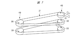
化学研磨処理部15は、帯状部材21の搬送方向で第1水洗い処理部14よりも下流に配置されている。また、化学研磨処理部15は、長辺11bに沿った方向で、短辺11dに対して第1水洗い処理部14よりも離れた位置に設けられている。化学研磨処理部15は、第3駆動ローラ部48及び第4駆動ローラ部49を有している。第3駆動ローラ部48は、図6のように、脱脂処理部13に設けた第1駆動ローラ部28と同じ構成を有している。また、第4駆動ローラ部49は、脱脂処理部13に設けた第2駆動ローラ部29と同じ構成を有している。   The chemical polishing processing unit 15 is disposed downstream of the first water washing processing unit 14 in the conveyance direction of the band-shaped member 21. In addition, the chemical polishing processing unit 15 is provided in a direction along the long side 11b at a position farther from the first water washing processing unit 14 with respect to the short side 11d. The chemical polishing processing unit 15 includes a third drive roller unit 48 and a fourth drive roller unit 49. The 3rd drive roller part 48 has the same structure as the 1st drive roller part 28 provided in the degreasing process part 13, as shown in FIG. Further, the fourth drive roller unit 49 has the same configuration as the second drive roller unit 29 provided in the degreasing processing unit 13.

帯状部材21は、第3駆動ローラ部48の駆動ローラ、及び第4駆動ローラ部49の駆動ローラに対して、図7のように巻き掛けられている。図7には、便宜上、駆動ローラ同士の間に高さ方向の隙間を空けて示してある。第1水洗い処理部14の駆動ローラ46aにより搬送方向が変換された帯状部材21は、第3駆動ローラ部48のうち、最上段に配置された駆動ローラ31に巻き掛けられて、搬送方向が約90度変換されて、第4駆動ローラ部49のうち、上側に位置する駆動ローラ38に巻き掛けられている。以下、帯状部材21は、駆動ローラ32、駆動ローラ39、駆動ローラ33に交互に巻き掛けられて、第3駆動ローラ部48と第4駆動ローラ部49との間を2往復する。帯状部材21は、第3駆動ローラ部48の駆動ローラと、第4駆動ローラ部49の駆動ローラとの間において、短辺11dと平行に直線状に搬送される。   The belt-like member 21 is wound around the drive roller of the third drive roller unit 48 and the drive roller of the fourth drive roller unit 49 as shown in FIG. For the sake of convenience, FIG. 7 shows a gap in the height direction between the drive rollers. The belt-like member 21 whose transport direction has been converted by the drive roller 46a of the first washing processing section 14 is wound around the drive roller 31 arranged at the top of the third drive roller section 48, and the transport direction is about It is converted by 90 degrees and is wound around the drive roller 38 located on the upper side of the fourth drive roller portion 49. Hereinafter, the belt-like member 21 is alternately wound around the driving roller 32, the driving roller 39, and the driving roller 33, and reciprocates between the third driving roller portion 48 and the fourth driving roller portion 49 twice. The belt-like member 21 is conveyed linearly in parallel with the short side 11d between the drive roller of the third drive roller unit 48 and the drive roller of the fourth drive roller unit 49.

また、化学研磨処理部15は、2つの化学研磨槽50を有している。2つの化学研磨槽50は、短辺11dに沿った方向で第3駆動ローラ部48と第4駆動ローラ部49との間に配置されている。2つの化学研磨槽50は、短辺11dと平行な長手形状を有している。2つの化学研磨槽50は、相互に平行に配置されている。さらに、2つの化学研磨槽50には、例えば、硫酸及び酸化剤を主成分とする研磨液が収容されている。さらに、化学研磨槽50は、図4のように長手方向の両端にガイドシール部材43,44がそれぞれ設けられている点は、脱脂槽42と同じである。帯状部材21は、第3駆動ローラ部48の駆動ローラと第4駆動ローラ部49の駆動ローラとの間を直線状に搬送されるときに、ガイドシール部材43のスリット43a及びガイドシール部材44のスリット44aを通り、化学研磨槽50内に出入りするように取り回されている。   The chemical polishing processing unit 15 includes two chemical polishing tanks 50. The two chemical polishing tanks 50 are disposed between the third drive roller unit 48 and the fourth drive roller unit 49 in the direction along the short side 11d. The two chemical polishing tanks 50 have a longitudinal shape parallel to the short side 11d. The two chemical polishing tanks 50 are arranged in parallel to each other. Further, the two chemical polishing tanks 50 contain, for example, a polishing liquid mainly composed of sulfuric acid and an oxidizing agent. Furthermore, the chemical polishing tank 50 is the same as the degreasing tank 42 in that guide seal members 43 and 44 are provided at both ends in the longitudinal direction as shown in FIG. When the belt-like member 21 is linearly conveyed between the drive roller of the third drive roller unit 48 and the drive roller of the fourth drive roller unit 49, the slit 43a of the guide seal member 43 and the guide seal member 44 It is routed through the slit 44a so as to enter and exit the chemical polishing tank 50.

第2水洗い処理部16は、帯状部材21の搬送方向で化学研磨処理部15よりも下流に配置されている。第2水洗い処理部16は、長辺11bに沿った方向で、短辺11dに対して化学研磨処理部15よりも離れた位置に設けられている。第2水洗い処理部16は駆動ローラ部51,52を有している。駆動ローラ部51,52は、短辺11dに沿った方向に所定間隔をおいて配置されている。駆動ローラ部51は長辺11c側に配置され、駆動ローラ部52は長辺11b側に配置されている。駆動ローラ部51は、垂直方向の軸線を中心として回転可能な駆動ローラ51aと、駆動ローラ51aを回転させる電動モータ(図示せず)とを有している。駆動ローラ部52は、垂直方向の軸線を中心として回転可能な駆動ローラ52aと、駆動ローラ52aを回転させる電動モータ(図示せず)とを有している。そして、第3駆動ローラ部48の駆動ローラ33により方向変換された帯状部材21は、駆動ローラ51aを経由して駆動ローラ52aに巻き掛けられている。第3駆動ローラ部48の駆動ローラ33、駆動ローラ51a,52aは同じ高さに設けられている。   The second water washing processing unit 16 is disposed downstream of the chemical polishing processing unit 15 in the conveying direction of the belt-like member 21. The 2nd water washing process part 16 is provided in the position along the long side 11b in the position away from the chemical polishing process part 15 with respect to the short side 11d. The second water washing processing unit 16 has driving roller portions 51 and 52. The drive roller portions 51 and 52 are arranged at a predetermined interval in the direction along the short side 11d. The driving roller unit 51 is disposed on the long side 11c side, and the driving roller unit 52 is disposed on the long side 11b side. The drive roller unit 51 includes a drive roller 51a that can rotate around a vertical axis, and an electric motor (not shown) that rotates the drive roller 51a. The drive roller unit 52 includes a drive roller 52a that can rotate around a vertical axis, and an electric motor (not shown) that rotates the drive roller 52a. The belt-like member 21 whose direction is changed by the drive roller 33 of the third drive roller portion 48 is wound around the drive roller 52a via the drive roller 51a. The drive roller 33 and the drive rollers 51a and 52a of the third drive roller unit 48 are provided at the same height.

また、第2水洗い処理部16は水洗い槽16aを有しており、水洗い槽16aは、短辺11dに沿った方向で駆動ローラ部51と駆動ローラ部52との間に設けられている。水洗い槽16aは、図5のように水洗い槽47と同様に構成されている。帯状部材21は,駆動ローラ51aから駆動ローラ52aに巻き掛けられている。帯状部材21は、駆動ローラ51aと駆動ローラ52aとの間で直線状に搬送される途中で、ガイドシール部材43のスリット43aを通り水洗い槽16aに出入りするように取り回されている。   Moreover, the 2nd water washing process part 16 has the water washing tank 16a, and the water washing tank 16a is provided between the drive roller part 51 and the drive roller part 52 in the direction along the short side 11d. The washing tank 16a is configured in the same manner as the washing tank 47 as shown in FIG. The belt-like member 21 is wound around the drive roller 52a from the drive roller 51a. The belt-like member 21 is routed so as to pass through the slit 43a of the guide seal member 43 into and out of the washing tank 16a while being conveyed linearly between the drive roller 51a and the drive roller 52a.

めっき処理部17は、帯状部材21の搬送方向で、第2水洗い処理部16の下流に配置されている。めっき処理部17は、長辺11bに沿った方向で、短辺11eに対して第2水洗い処理部16よりも近い位置に配置されている。めっき処理部17は第1処理部53及び第2処理部54を有する。第1処理部53は、長辺11bに沿った方向で、第2水洗い処理部16と第2処理部54との間に配置されている。第1処理部は、第5駆動ローラ部55及び第6駆動ローラ部56を有している。第5駆動ローラ部55の構成は、図2のように第1駆動ローラ部28の構成と同じである。また、第6駆動ローラ部56の構成は、第2駆動ローラ部29の構成と同じである。   The plating processing unit 17 is disposed downstream of the second water washing processing unit 16 in the conveying direction of the band-shaped member 21. The plating process part 17 is arrange | positioned in the direction along the long side 11b in the position nearer than the 2nd washing process part 16 with respect to the short side 11e. The plating processing unit 17 includes a first processing unit 53 and a second processing unit 54. The 1st process part 53 is arrange | positioned between the 2nd washing process part 16 and the 2nd process part 54 in the direction along the long side 11b. The first processing unit includes a fifth drive roller unit 55 and a sixth drive roller unit 56. The configuration of the fifth drive roller unit 55 is the same as the configuration of the first drive roller unit 28 as shown in FIG. Further, the configuration of the sixth drive roller unit 56 is the same as the configuration of the second drive roller unit 29.

帯状部材21は、第5駆動ローラ部55及び第6駆動ローラ部56において、各駆動ローラに対して図3のように巻き掛けられている。駆動ローラ52aにより方向変換された帯状部材21は、駆動ローラ33により方向変換されて駆動ローラ39に巻き掛けられ、さらに帯状部材21は駆動ローラ39により方向変換されて、駆動ローラ32に巻き掛けられている。さらに、帯状部材21は、駆動ローラ32により方向変換されて駆動ローラ38に巻き掛けられ、駆動ローラ38で方向変換された帯状部材21は、駆動ローラ31に巻き掛けられている。そして、第5駆動ローラ部55の最上段の駆動ローラ31により方向変換された帯状部材21は、第2処理部54へ搬送される。なお、第5駆動ローラ部55の駆動ローラ31,32,33及び第6駆動ローラ部56の駆動ローラ38,39は、電源(図示せず)のマイナス端子(陰極)に接続されている。   The belt-like member 21 is wound around each drive roller in the fifth drive roller portion 55 and the sixth drive roller portion 56 as shown in FIG. The band-shaped member 21 whose direction has been changed by the driving roller 52 a is changed in direction by the driving roller 33 and wound around the driving roller 39, and the direction of the band-shaped member 21 is changed by the driving roller 39 and wound around the driving roller 32. ing. Further, the belt-like member 21 is changed in direction by the driving roller 32 and wound around the driving roller 38, and the band-like member 21 whose direction is changed by the driving roller 38 is wound around the driving roller 31. Then, the belt-like member 21 whose direction has been changed by the uppermost drive roller 31 of the fifth drive roller unit 55 is conveyed to the second processing unit 54. The drive rollers 31, 32, 33 of the fifth drive roller unit 55 and the drive rollers 38, 39 of the sixth drive roller unit 56 are connected to a negative terminal (cathode) of a power source (not shown).

さらに、第1処理部53は、2つのめっき槽57を有している。2つのめっき槽57は、短辺11eに沿った方向で第5駆動ローラ部55と第6駆動ローラ部56との間に配置されている。2つのめっき槽57は、短辺11eと平行な長手形状を有している。2つのめっき槽57は、相互に平行に配置されている。さらに、2つのめっき槽57内にはめっき液が収容されており、かつ、アノードバスケット(図示せず)が設けられている。アノードバスケットは、電源のプラス端子(陽極)に接続されている。さらに、めっき槽57は、図4のように長手方向の両端に、ガイドシール部材43,44がそれぞれ設けられている点は、脱脂槽42と同じである。第5駆動ローラ部55の駆動ローラと、第6駆動ローラ部56の駆動ローラとの間を直線状に搬送される帯状部材21は、ガイドシール部材43のスリット43a及びガイドシール部材44のスリット44aを通り、2つのめっき槽57に交互に出入りするようになっている。   Further, the first processing unit 53 has two plating tanks 57. The two plating tanks 57 are disposed between the fifth drive roller portion 55 and the sixth drive roller portion 56 in the direction along the short side 11e. The two plating tanks 57 have a longitudinal shape parallel to the short side 11e. The two plating tanks 57 are arranged in parallel to each other. Furthermore, the plating solution is accommodated in the two plating tanks 57, and an anode basket (not shown) is provided. The anode basket is connected to the positive terminal (anode) of the power source. Further, the plating tank 57 is the same as the degreasing tank 42 in that guide seal members 43 and 44 are provided at both ends in the longitudinal direction as shown in FIG. The belt-like member 21 conveyed linearly between the drive roller of the fifth drive roller portion 55 and the drive roller of the sixth drive roller portion 56 is a slit 43a of the guide seal member 43 and a slit 44a of the guide seal member 44. Through the two plating tanks 57 alternately.

一方、第2処理部54は、第7駆動ローラ部58及び第8駆動ローラ部59を有している。第7駆動ローラ部58は長辺11b側に配置され、第8駆動ローラ部59は長辺11c側に配置されている。第7駆動ローラ部58は、図2のように第1駆動ローラ部28と同じ構成を有する。また、第8駆動ローラ部59は、第2駆動ローラ部29同じ構成を有する。第7駆動ローラ部58の駆動ローラ及び第8駆動ローラ部59の駆動ローラに対する帯状部材21の巻き掛け状態は、図8のようになっている。図8には、便宜上、各駆動ローラ同士の間には高さ方向の隙間を空けて示してある。   On the other hand, the second processing unit 54 includes a seventh drive roller unit 58 and an eighth drive roller unit 59. The seventh drive roller portion 58 is disposed on the long side 11b side, and the eighth drive roller portion 59 is disposed on the long side 11c side. The seventh drive roller unit 58 has the same configuration as the first drive roller unit 28 as shown in FIG. Further, the eighth drive roller unit 59 has the same configuration as the second drive roller unit 29. FIG. 8 shows a state in which the belt-like member 21 is wound around the driving roller of the seventh driving roller portion 58 and the driving roller of the eighth driving roller portion 59. For the sake of convenience, FIG. 8 shows a gap in the height direction between the drive rollers.

第5駆動ローラ部55の駆動ローラ31から搬送された帯状部材21は、第7駆動ローラ部58における最上段の駆動ローラ31により搬送方向が変換され、第8駆動ローラ部59の駆動ローラ38に巻き掛けられている。以下、帯状部材21は、駆動ローラ32、駆動ローラ39、駆動ローラ33に順次巻き掛けられて搬送方向が変換され、帯状部材21は、湯洗い処理部18へ搬送される。   The belt-like member 21 conveyed from the drive roller 31 of the fifth drive roller unit 55 is changed in the conveyance direction by the uppermost drive roller 31 in the seventh drive roller unit 58 and is transferred to the drive roller 38 of the eighth drive roller unit 59. It is wrapped around. Hereinafter, the belt-like member 21 is wound around the driving roller 32, the driving roller 39, and the driving roller 33 in order to change the conveyance direction, and the belt-like member 21 is conveyed to the hot water washing processing unit 18.

また、第2処理部54には2つのめっき槽60が配置されている。2つのめっき槽60は、短辺11eに沿った方向で第7駆動ローラ部58と第8駆動ローラ部59との間に相互に平行に配置されている。2つのめっき槽60は、図4のように2つのめっき槽57と同じ構成を有している。2つのめっき槽60は短辺11eと平行な方向に沿って長尺形状に構成されている。そして、帯状部材21は、第7駆動ローラ部58の駆動ローラと、第8駆動ローラ部59の駆動ローラとの間を直線状に搬送されるときに、ガイドシール部材43のスリット43a及びガイドシール部材44のスリット44aを通り、2つのめっき槽60に交互に出入りするように取り回されている。   Two plating tanks 60 are disposed in the second processing unit 54. The two plating tanks 60 are disposed parallel to each other between the seventh drive roller portion 58 and the eighth drive roller portion 59 in the direction along the short side 11e. The two plating tanks 60 have the same configuration as the two plating tanks 57 as shown in FIG. The two plating tanks 60 are formed in a long shape along a direction parallel to the short side 11e. When the belt-like member 21 is linearly conveyed between the drive roller of the seventh drive roller unit 58 and the drive roller of the eighth drive roller unit 59, the slit 43a and the guide seal of the guide seal member 43 are used. It passes around the slits 44a of the member 44 so as to alternately enter and exit the two plating tanks 60.

湯洗い処理部18は、長辺11bに沿った方向で、短辺11eとめっき処理部17との間に配置されている。湯洗い処理部18は、3個の駆動ローラ部61,62,63を有している。駆動ローラ部61,63は、長辺11b側に並んで配置されている。駆動ローラ部62は、長辺11c側に配置されている。   The hot water treatment unit 18 is disposed between the short side 11e and the plating unit 17 in a direction along the long side 11b. The hot water washing processing unit 18 includes three drive roller units 61, 62, and 63. The drive roller portions 61 and 63 are arranged side by side on the long side 11b side. The drive roller unit 62 is disposed on the long side 11c side.

駆動ローラ部61は、垂直な軸線を中心として回転可能な駆動ローラ61aと、駆動ローラ61aを回転させる電動モータ(図示せず)とを有している。駆動ローラ部62は、垂直な軸線を中心として回転可能な駆動ローラ62aと、駆動ローラ62aを回転させる電動モータ(図示せず)とを有している。駆動ローラ部63は、垂直な軸線を中心として回転可能な駆動ローラ63aと、駆動ローラ63aを回転させる電動モータ(図示せず)とを有している。駆動ローラ61a,62a,63aは、第7駆動ローラ部58の駆動ローラ33と同じ高さに設けられている。   The drive roller unit 61 includes a drive roller 61a that can rotate around a vertical axis, and an electric motor (not shown) that rotates the drive roller 61a. The drive roller unit 62 includes a drive roller 62a that can rotate around a vertical axis, and an electric motor (not shown) that rotates the drive roller 62a. The drive roller unit 63 includes a drive roller 63a that can rotate around a vertical axis, and an electric motor (not shown) that rotates the drive roller 63a. The drive rollers 61a, 62a, 63a are provided at the same height as the drive roller 33 of the seventh drive roller portion 58.

そして、帯状部材21は、第7駆動ローラ部58の駆動ローラ33を経由して、湯洗い処理部18へ搬送される。すると、その帯状部材21は、駆動ローラ61aにより搬送方向が約90度変換されて、駆動ローラ62aに巻き掛けられている。帯状部材21は、駆動ローラ62aにより搬送方向が約180度変換されて、駆動ローラ63aに巻き掛けられている。   Then, the belt-like member 21 is conveyed to the hot water washing processing unit 18 via the driving roller 33 of the seventh driving roller unit 58. Then, the belt-like member 21 is wound around the drive roller 62a after the conveyance direction is changed by about 90 degrees by the drive roller 61a. The belt-like member 21 is wound around the drive roller 63a after the conveyance direction is changed by about 180 degrees by the drive roller 62a.

湯洗い処理部18は、2個の湯洗い槽64を有している。各湯洗い槽64は、駆動ローラから駆動ローラへ向けて帯状部材21が搬送される経路に、長手方向に沿って直線状に設けられている。すなわち、2個の湯洗い槽64は短辺11eと平行に配置されている。2個の湯洗い槽64における長手方向の両端には、図5のようにガイドシール部材43がそれぞれ取り付けられている。そして、帯状部材21は、駆動ローラ61aから駆動ローラ62aに向けて直線状に搬送される場合、駆動ローラ62aから駆動ローラ63aに向けて直線状に搬送される場合のいずれにおいても、スリット43aを通過して湯洗い槽64に出入りするように取り回されている。なお、湯洗い処理部18の駆動ローラ63aで方向変換された帯状部材21は、乾燥処理部19へ搬送される。   The hot water treatment unit 18 has two hot water washing tanks 64. Each hot water bath 64 is provided in a straight line along the longitudinal direction in a path along which the belt-like member 21 is conveyed from the drive roller toward the drive roller. That is, the two hot water baths 64 are arranged in parallel with the short side 11e. Guide seal members 43 are attached to both ends in the longitudinal direction of the two hot water baths 64 as shown in FIG. The belt-like member 21 is provided with the slit 43a in both cases where it is conveyed linearly from the driving roller 61a toward the driving roller 62a and when it is conveyed linearly from the driving roller 62a toward the driving roller 63a. It is routed to pass through and enter the hot water bath 64. The belt-like member 21 whose direction has been changed by the driving roller 63 a of the hot water washing processing unit 18 is conveyed to the drying processing unit 19.

乾燥処理部19は、長辺11bに沿った方向で短辺11eと湯洗い処理部18との間に設けられている。乾燥処理部19は、第9駆動ローラ部65及び第10駆動ローラ部66を備えている。第9駆動ローラ部65は、長辺11b側に配置され、第10駆動ローラ部66は長辺11c側に配置されている。つまり、第9駆動ローラ部65及び第10駆動ローラ部66は、短辺11e方向に所定間隔をおいて配置されている。第9駆動ローラ部65は、図2のように第1駆動ローラ部28と同じ構成を有している。また、第10駆動ローラ部66は、第2駆動ローラ部29と同じ構成を有している。   The drying processing unit 19 is provided between the short side 11e and the hot water washing processing unit 18 in the direction along the long side 11b. The drying processing unit 19 includes a ninth driving roller unit 65 and a tenth driving roller unit 66. The ninth drive roller unit 65 is disposed on the long side 11b side, and the tenth drive roller unit 66 is disposed on the long side 11c side. That is, the ninth drive roller portion 65 and the tenth drive roller portion 66 are arranged at a predetermined interval in the direction of the short side 11e. The ninth drive roller unit 65 has the same configuration as the first drive roller unit 28 as shown in FIG. Further, the tenth driving roller portion 66 has the same configuration as the second driving roller portion 29.

そして、駆動ローラ63aにより方向変換された帯状部材21は、図3のように第9駆動ローラ部65の駆動ローラ33に巻き掛けられており、以下、第10駆動ローラ部66の駆動ローラと第9駆動ローラ部65の駆動ローラとに交互に巻き掛けられている。すなわち、帯状部材21は、駆動ローラ33により方向変換されて駆動ローラ39に巻き掛けられている。さらに、帯状部材21は、駆動ローラ39により方向変換されて、駆動ローラ32に巻き掛けられている。さらに、帯状部材21は、駆動ローラ32により方向変換されて駆動ローラ38に巻き掛けられている。駆動ローラ38で方向変換された帯状部材21は、駆動ローラ31に巻き掛けられている。そして、帯状部材21は、第9駆動ローラ部65の最上段の駆動ローラ31により方向変換されて、巻取り部20へ搬送される。   The belt-like member 21 whose direction is changed by the drive roller 63a is wound around the drive roller 33 of the ninth drive roller portion 65 as shown in FIG. It is alternately wound around the drive roller of the 9 drive roller portion 65. That is, the belt-like member 21 is changed in direction by the drive roller 33 and is wound around the drive roller 39. Further, the belt-like member 21 has its direction changed by the driving roller 39 and is wound around the driving roller 32. Further, the belt-like member 21 is changed in direction by the driving roller 32 and is wound around the driving roller 38. The belt-like member 21 whose direction has been changed by the driving roller 38 is wound around the driving roller 31. The direction of the belt-like member 21 is changed by the uppermost drive roller 31 of the ninth drive roller unit 65, and the belt-like member 21 is conveyed to the winding unit 20.

また、乾燥処理部19は2つの乾燥機67を有している。2つの乾燥機67は、短辺11eに沿った方向で、第9駆動ローラ部65と第10駆動ローラ部66との間に配置されている。2つの乾燥機67は、共に短辺11eと平行な長尺形状に構成されている。乾燥機67には、送風機等によって空気に強制対流を生じさせるもの、または、ヒータの熱によって温められた温風を帯状部材21に吹き付けるもの等が含まれる。   Further, the drying processing unit 19 has two dryers 67. The two dryers 67 are disposed between the ninth drive roller unit 65 and the tenth drive roller unit 66 in the direction along the short side 11e. The two dryers 67 are both configured in a long shape parallel to the short side 11e. The dryer 67 includes one that causes forced convection in the air by a blower or the like, or one that blows warm air heated by the heat of the heater onto the belt-like member 21.

一方、巻取り部20は短辺11eに沿って設けられている。巻取り部20は方向変換ローラ69を有している。方向変換ローラ69は、帯状部材21の搬送方向を変換する機構である。さらに、方向変換ローラ69は、垂直方向の軸線を中心として回転可能に構成されている。巻取り部20は、一対のガイドローラ70を有している。一対のガイドローラ70は、水平方向の軸線を中心として回転可能であり、一対のガイドローラ70は可動台71により支持されている。可動台71は、ガイドレール72に沿って水平方向に移動可能に構成されている。   On the other hand, the winding part 20 is provided along the short side 11e. The winding unit 20 has a direction changing roller 69. The direction conversion roller 69 is a mechanism that changes the conveyance direction of the belt-like member 21. Further, the direction changing roller 69 is configured to be rotatable about a vertical axis. The winding unit 20 has a pair of guide rollers 70. The pair of guide rollers 70 are rotatable about a horizontal axis, and the pair of guide rollers 70 are supported by a movable base 71. The movable table 71 is configured to be movable in the horizontal direction along the guide rail 72.

巻取り部20は巻取りリール73を有しており、巻取りリール73は電動モータ74により回転される構成となっている。巻取りリール73の回転軸75は、水平方向の軸線を中心として回転可能である。電動モータ74のトルクを回転軸75に伝達する経路には、減速機(図示せず)が設けられている。一対のガイドローラ70は、帯状部材21の搬送方向で方向変換ローラ69よりも下流に配置され、巻取りリール73は、帯状部材21の搬送方向において一対のガイドローラ70よりも下流に配置されている。つまり、一対のガイドローラ70は、短辺11eに沿った方向で方向変換ローラ69と巻取りリール73との間に設けられている。上記のように、めっき装置10は、水平方向の平面内において、供給部12、脱脂処理部13、第1水洗い処理部14、化学研磨処理部15、第2水洗い処理部16、めっき処理部17、湯洗い処理部18、乾燥処理部19、巻取り部20が相互に平行に配置されている。   The winding unit 20 includes a winding reel 73, and the winding reel 73 is configured to be rotated by an electric motor 74. The rotation shaft 75 of the take-up reel 73 is rotatable around a horizontal axis. A speed reducer (not shown) is provided in a path for transmitting the torque of the electric motor 74 to the rotary shaft 75. The pair of guide rollers 70 are disposed downstream of the direction changing roller 69 in the transport direction of the belt-shaped member 21, and the take-up reel 73 is disposed downstream of the pair of guide rollers 70 in the transport direction of the belt-shaped member 21. Yes. That is, the pair of guide rollers 70 is provided between the direction changing roller 69 and the take-up reel 73 in the direction along the short side 11e. As described above, the plating apparatus 10 includes the supply unit 12, the degreasing unit 13, the first washing unit 14, the chemical polishing unit 15, the second washing unit 16, and the plating unit 17 in a horizontal plane. The hot water washing processing unit 18, the drying processing unit 19, and the winding unit 20 are arranged in parallel to each other.

図1に示すめっき装置10により、帯状部材21にめっき処理を施す工程を説明する。帯状部材21は、搬送方向の先端が巻取りリール73に巻かれた状態で各電動モータが所定方向に回転して長さ方向に搬送され、最終的に巻取りリール73に巻かれている。すると、供給リール22から繰り出された帯状部材21は、一対のガイドローラ24により、表裏面が略水平面に沿った状態のまま搬送される。一対のガイドローラ24によってガイドされた帯状部材21は、方向変換ローラ27に巻き掛けられて案内される。一対のガイドローラ24は、水平方向の軸線を中心として回転する一方、方向変換ローラ27は、垂直方向の軸線を中心として回転する。このため、帯状部材21は、一対のガイドローラ24を離れてから、方向変換ローラ27に接触するまでの間に、厚さ方向に約90度捻られる。すなわち、帯状部材21は、表裏面が略垂直方向に沿った状態で搬送される。これ以後、帯状部材21は、巻取り部20へ搬送されるまでの間、常時、表裏面が略垂直方向に沿った状態に保持されて搬送される。そして、帯状部材21は方向変換ローラ27により、搬送方向が約90度変換されて、脱脂処理部13へ搬送される。   A process of performing a plating process on the belt-like member 21 by the plating apparatus 10 shown in FIG. 1 will be described. The belt-like member 21 is wound around the take-up reel 73 as the electric motor rotates in a predetermined direction with the leading end in the carrying direction wound around the take-up reel 73 and is conveyed in the length direction. Then, the belt-like member 21 fed out from the supply reel 22 is conveyed by the pair of guide rollers 24 while the front and back surfaces are substantially along the horizontal plane. The belt-like member 21 guided by the pair of guide rollers 24 is wound around the direction changing roller 27 and guided. The pair of guide rollers 24 rotate about the horizontal axis, while the direction changing roller 27 rotates about the vertical axis. For this reason, the band-shaped member 21 is twisted by about 90 degrees in the thickness direction after it leaves the pair of guide rollers 24 until it comes into contact with the direction changing roller 27. That is, the belt-like member 21 is conveyed in a state where the front and back surfaces are substantially along the vertical direction. Thereafter, the belt-like member 21 is always conveyed while being held in a state in which the front and back surfaces are substantially along the vertical direction until it is conveyed to the winding unit 20. Then, the belt-shaped member 21 is transported to the degreasing unit 13 after the transport direction is changed by about 90 degrees by the direction conversion roller 27.

脱脂処理部13へ搬送された帯状部材21は、図3のように第1駆動ローラ部28のうち最下段の駆動ローラ33に巻き掛けられている。帯状部材21は、次いで駆動ローラ39、駆動ローラ32、駆動ローラ38の順に巻き掛けられることで、帯状部材21は搬送方向が変換される。すなわち、帯状部材21は、第1駆動ローラ部28と第2駆動ローラ部29との間を2往復する。ここで、第1駆動ローラ部28を構成する3個の駆動ローラ31,32,33は、配置高さが異なる。また、第2駆動ローラ部29を構成する2個の駆動ローラ38,39は、配置高さが異なる。このため、帯状部材21は、第1駆動ローラ部28と第2駆動ローラ部29との間を、螺旋状に2往復する過程で部分的に接触することがない。そして、帯状部材21は、第1駆動ローラ部28と第2駆動ローラ部29との間を直線状に搬送される途中で、脱脂槽42を通過する。すなわち、帯状部材21は、ガイドシール部材43,44のスリット43a,44aを経由して2つの脱脂槽42の内部に別々に出入りし、帯状部材21に対する脱脂処理が行われる。帯状部材21は脱脂処理が終了すると、第1駆動ローラ部28の最上段の駆動ローラ31により搬送方向が変換されて、第1水洗い処理部14へ搬送される。   The belt-like member 21 conveyed to the degreasing unit 13 is wound around the lowermost drive roller 33 of the first drive roller unit 28 as shown in FIG. Next, the belt-like member 21 is wound around the drive roller 39, the drive roller 32, and the drive roller 38 in this order, so that the conveyance direction of the belt-like member 21 is changed. That is, the belt-like member 21 reciprocates between the first drive roller portion 28 and the second drive roller portion 29 twice. Here, the three drive rollers 31, 32, and 33 constituting the first drive roller portion 28 have different arrangement heights. Further, the two drive rollers 38 and 39 constituting the second drive roller unit 29 have different arrangement heights. For this reason, the belt-like member 21 does not partially contact between the first drive roller portion 28 and the second drive roller portion 29 in the process of reciprocating twice in a spiral manner. The belt-like member 21 passes through the degreasing tank 42 while being conveyed linearly between the first drive roller portion 28 and the second drive roller portion 29. That is, the strip-shaped member 21 enters and exits the two degreasing tanks 42 via the slits 43a and 44a of the guide seal members 43 and 44, and the strip-shaped member 21 is degreased. When the degreasing process is finished, the belt-like member 21 is transported to the first water washing processing unit 14 by changing the transport direction by the uppermost drive roller 31 of the first drive roller unit 28.

第1水洗い処理部14へ搬送された帯状部材21は、駆動ローラ45aに巻き掛けられて搬送方向が変換され、駆動ローラ46aに巻き掛けられている。帯状部材21は、駆動ローラ45aを離れてから駆動ローラ46aに巻き掛かるまでの間、直線状に搬送される。このとき、帯状部材21は、ガイドシール部材43のスリット43aを経由して水洗い槽47に入る。帯状部材21は水洗いされた後、水洗い槽47の外部に出る。帯状部材21は、水洗い槽47から出ると、駆動ローラ46aにより搬送方向が約90度変換され、化学研磨処理部15へ搬送される。   The belt-like member 21 conveyed to the first water washing processing unit 14 is wound around the driving roller 45a, the conveying direction is changed, and is wound around the driving roller 46a. The belt-like member 21 is conveyed linearly from the time when it leaves the driving roller 45a until it is wound around the driving roller 46a. At this time, the belt-shaped member 21 enters the washing tank 47 through the slit 43 a of the guide seal member 43. After the belt-like member 21 is washed with water, it goes out of the washing tank 47. When the belt-like member 21 comes out of the washing tank 47, the conveyance direction is changed by about 90 degrees by the driving roller 46 a and is conveyed to the chemical polishing processing unit 15.

化学研磨処理部15へ搬送された帯状部材21は、図7のように第3駆動ローラ部48の最上段の駆動ローラ31に巻き掛けられて、搬送方向が約90度変換される。帯状部材21は、駆動ローラ38、駆動ローラ32、駆動ローラ39、駆動ローラ33に順次巻き掛けられることで、搬送方向及び高さが変換される。すなわち、帯状部材21は第3駆動ローラ部48と第4駆動ローラ部49との間を2往復し、全体として螺旋状に搬送される。   The belt-like member 21 conveyed to the chemical polishing processing unit 15 is wound around the uppermost drive roller 31 of the third drive roller unit 48 as shown in FIG. 7, and the conveyance direction is changed by about 90 degrees. The belt-like member 21 is sequentially wound around the driving roller 38, the driving roller 32, the driving roller 39, and the driving roller 33, so that the conveying direction and the height are changed. That is, the belt-like member 21 reciprocates twice between the third drive roller portion 48 and the fourth drive roller portion 49, and is conveyed spirally as a whole.

そして、帯状部材21は、第3駆動ローラ部48と第4駆動ローラ部49との間を直線状に搬送される途中で、2つの化学研磨槽50を交互に2回づつ通過する。すなわち、帯状部材21は、ガイドシール部材43,44のスリット43a,44aを経由して化学研磨槽50に出入りし、帯状部材21の表裏面が研磨される。帯状部材21は研磨処理が終了すると、第4駆動ローラ部49の最下段の駆動ローラ33により搬送方向が変換されて、第2水洗い処理部16へ搬送される。   The belt-like member 21 passes through the two chemical polishing tanks 50 alternately twice while being conveyed linearly between the third drive roller portion 48 and the fourth drive roller portion 49. That is, the strip member 21 enters and exits the chemical polishing tank 50 through the slits 43a and 44a of the guide seal members 43 and 44, and the front and back surfaces of the strip member 21 are polished. When the polishing process of the belt-like member 21 is completed, the transport direction is changed by the lowermost drive roller 33 of the fourth drive roller unit 49, and the belt-shaped member 21 is transported to the second water washing processing unit 16.

第2水洗い処理部16へ搬送された帯状部材21は、駆動ローラ51aから駆動ローラ52aへ直線状に搬送される途中で、水洗い槽16a内を通ることで水洗いされる。帯状部材21は、水洗い槽16aで水洗いされた後、駆動ローラ52aで搬送方向が変換されて、めっき処理部17の第1処理部53へ搬送される。   The belt-like member 21 conveyed to the second water washing processing unit 16 is washed with water by passing through the water washing tank 16a while being linearly conveyed from the driving roller 51a to the driving roller 52a. The belt-like member 21 is washed with water in the washing tank 16 a, then the conveyance direction is changed by the driving roller 52 a, and conveyed to the first processing unit 53 of the plating processing unit 17.

第1処理部53へ搬送された帯状部材21は、図3のように最下段の駆動ローラ33に巻き掛けられて方向変換される。ついで、帯状部材21は、駆動ローラ39、駆動ローラ32、駆動ローラ38、駆動ローラ31に交互に巻き掛けられることで、方向変換が繰り返される。つまり、帯状部材21は、第5駆動ローラ部55と第6駆動ローラ部56との間を2往復する。また、帯状部材21は、全体として螺旋状に搬送されながら徐々に上方へ移動する。そして、帯状部材21は、駆動ローラ同士の間を直線状に搬送されるとき、2つのめっき槽57を交互に通過する。   The belt-like member 21 transported to the first processing unit 53 is wound around the lowermost drive roller 33 as shown in FIG. Next, the belt-like member 21 is alternately wound around the driving roller 39, the driving roller 32, the driving roller 38, and the driving roller 31, whereby the direction change is repeated. That is, the belt-like member 21 reciprocates between the fifth drive roller portion 55 and the sixth drive roller portion 56 twice. Moreover, the strip | belt-shaped member 21 moves upwards gradually, being conveyed helically as a whole. And the strip | belt-shaped member 21 passes the two plating tanks 57 alternately, when conveyed between drive rollers linearly.

めっき槽57内に設けられたアノードバスケットはプラス端子に接続され、各駆動ローラはマイナス端子に接続されているので、帯状部材21がめっき槽57を通過する際に、アノードバスケットの錫合金は、めっき液中にイオンとなって入り込む。めっき液中の金属イオンは、帯状部材21の表面に金属原子として析出し、帯状部材21の表裏面にめっき層が形成される。帯状部材21に形成されるめっき層の厚さは、電源から供給される電力の電流値、帯状部材21の搬送速度により決定される。帯状部材21の搬送速度は、各電動モータの回転速度を制御することで調整できる。   Since the anode basket provided in the plating tank 57 is connected to the plus terminal and each drive roller is connected to the minus terminal, when the strip member 21 passes through the plating tank 57, the tin alloy of the anode basket is It enters into the plating solution as ions. Metal ions in the plating solution are deposited as metal atoms on the surface of the band-shaped member 21, and a plating layer is formed on the front and back surfaces of the band-shaped member 21. The thickness of the plating layer formed on the belt-like member 21 is determined by the current value of power supplied from the power source and the conveyance speed of the belt-like member 21. The conveyance speed of the belt-like member 21 can be adjusted by controlling the rotation speed of each electric motor.

第1処理部53でめっき層が形成された帯状部材21は、駆動ローラ31を経由して第2処理部54へ搬送され、図8のように第7駆動ローラ部58の最上段の駆動ローラ31へ巻掛けられる。そして、帯状部材21は、第7駆動ローラ部58と第8駆動ローラ部59との間を2往復する。つまり、帯状部材21は、駆動ローラ31、駆動ローラ38、駆動ローラ32、駆動ローラ39、駆動ローラ33に交互に巻き掛けられることで、方向変換が繰り返される。   The belt-like member 21 on which the plating layer is formed by the first processing unit 53 is conveyed to the second processing unit 54 via the driving roller 31 and is the uppermost driving roller of the seventh driving roller unit 58 as shown in FIG. 31 is wound around. The belt-like member 21 reciprocates between the seventh drive roller portion 58 and the eighth drive roller portion 59 twice. In other words, the belt-like member 21 is alternately wound around the driving roller 31, the driving roller 38, the driving roller 32, the driving roller 39, and the driving roller 33, so that the direction change is repeated.

このようにして、帯状部材21は、第5駆動ローラ部55と第6駆動ローラ部56との間を2往復する。また、帯状部材21は、全体として螺旋状に搬送されながら徐々に下方へ移動する。第2処理部54において、帯状部材21が駆動ローラ同士の間を直線状に搬送される途中でめっき槽60に出入りし、めっき槽57と同様の原理で帯状部材21の表裏面にめっき処理が施される。すなわち、帯状部材21は、異なる高さを搬送される途中でめっき処理が複数回施される。   In this way, the belt-like member 21 reciprocates between the fifth drive roller portion 55 and the sixth drive roller portion 56 twice. Moreover, the strip | belt-shaped member 21 moves below gradually, being conveyed helically as a whole. In the second processing unit 54, the strip member 21 enters and leaves the plating tank 60 while being linearly conveyed between the drive rollers, and plating treatment is performed on the front and back surfaces of the strip member 21 on the same principle as the plating tank 57. Applied. That is, the belt-like member 21 is subjected to the plating process a plurality of times while being conveyed at different heights.

そして、めっき処理が行われた帯状部材21は、第2処理部54の最下段の駆動ローラ33により方向変換され、湯洗い処理部18へ搬送される。湯洗い処理部18に搬送された帯状部材21は、駆動ローラ61aから駆動ローラ62aへ直線状に搬送されるときに、湯洗い槽64内で湯洗いされる。また、駆動ローラ62aにより搬送方向が変換された帯状部材21は、駆動ローラ62aから駆動ローラ63aへ直線状に搬送されるときに、湯洗い槽64内で再度湯洗いされる。   Then, the strip-shaped member 21 that has been subjected to the plating process is changed in direction by the lowermost drive roller 33 of the second processing unit 54 and conveyed to the hot water washing processing unit 18. The belt-like member 21 conveyed to the hot water washing processing unit 18 is washed with hot water in the hot water washing tank 64 when being conveyed linearly from the driving roller 61a to the driving roller 62a. Further, the belt-like member 21 whose conveyance direction has been changed by the drive roller 62a is again washed in the hot water bath 64 when being conveyed linearly from the drive roller 62a to the drive roller 63a.

湯洗い処理部18で湯洗いされた帯状部材21は、駆動ローラ63aにより乾燥処理部19へ搬送される。乾燥処理部19に搬送された帯状部材21は、第9駆動ローラ部65の最下段の駆動ローラ33に巻き掛けられる。帯状部材21は、さらに駆動ローラ39、駆動ローラ32、駆動ローラ38、駆動ローラ31により順次折り返され、第9駆動ローラ部65と、第10駆動ローラ部66との間を2往復する。このようにして、帯状部材21は、乾燥処理部19では全体として螺旋状に搬送される。また、帯状部材21は、徐々に上方に向けて搬送される。そして、駆動ローラ同士の間で直線状に搬送される箇所で、乾燥機67により乾燥される。その後、乾燥された帯状部材21は、第9駆動ローラ部65の最上段の駆動ローラ31により方向変換されて、巻取り部20へ搬送される。   The belt-like member 21 washed with hot water in the hot water treatment section 18 is conveyed to the drying processing section 19 by the drive roller 63a. The belt-like member 21 conveyed to the drying processing unit 19 is wound around the lowermost drive roller 33 of the ninth drive roller unit 65. Further, the belt-like member 21 is sequentially folded back by the driving roller 39, the driving roller 32, the driving roller 38, and the driving roller 31, and reciprocates twice between the ninth driving roller portion 65 and the tenth driving roller portion 66. In this way, the belt-like member 21 is conveyed spirally as a whole in the drying processing unit 19. Moreover, the strip | belt-shaped member 21 is conveyed toward upper direction gradually. And it dries with the dryer 67 in the location conveyed linearly between drive rollers. Thereafter, the direction of the dried belt-like member 21 is changed by the uppermost drive roller 31 of the ninth drive roller unit 65 and conveyed to the winding unit 20.

巻取り部20では、帯状部材21が方向変換ローラ69から一対のガイドローラ70に至る経路で、帯状部材21は厚さ方向に約90度捻られて、表裏面が水平面に沿った状態に姿勢が戻される。一対のガイドローラ70により搬送された帯状部材21は、巻取りリール73により巻き取られる。   In the winding unit 20, the belt-like member 21 is routed from the direction changing roller 69 to the pair of guide rollers 70, and the belt-like member 21 is twisted by about 90 degrees in the thickness direction so that the front and back surfaces are along the horizontal plane. Is returned. The belt-like member 21 conveyed by the pair of guide rollers 70 is taken up by the take-up reel 73.

このように、本実施形態のめっき装置10においては、各機構及び各処理部が、水平方向の平面内で相互に平行に配置されている。このため、水平方向の平面内におけるめっき装置10の専有面積が広くなることを抑制できる。また、めっき装置10では、帯状部材21が水平方向の平面内を全体として蛇行して搬送されるため、各処理部を長手方向に直線状に並べる場合に比べて、一方向における全長を短くすることができる。また、めっき装置10は、脱脂処理部13、化学研磨処理部15、めっき処理部17、乾燥処理部19のそれぞれにおいて、複数の駆動ローラが異なる高さに設けられており、帯状部材21は駆動ローラ同士の間を行き来することで、帯状部材21が高さ方向に螺旋状に搬送される。したがって、水平方向の平面内において、単位面積当たりにおける帯状部材21の搬送長さを長くすることができ、各種の処理効率を高くすること(向上すること)ができる。   Thus, in the plating apparatus 10 of this embodiment, each mechanism and each process part are arrange | positioned mutually parallel in the plane of a horizontal direction. For this reason, it can suppress that the exclusive area of the plating apparatus 10 in the plane of a horizontal direction becomes large. Moreover, in the plating apparatus 10, since the strip | belt-shaped member 21 meanders and is conveyed as a whole within the plane of a horizontal direction, compared with the case where each process part is put in a line in the longitudinal direction, the full length in one direction is shortened. be able to. In the plating apparatus 10, a plurality of driving rollers are provided at different heights in each of the degreasing processing unit 13, the chemical polishing processing unit 15, the plating processing unit 17, and the drying processing unit 19, and the belt-shaped member 21 is driven. By moving back and forth between the rollers, the belt-like member 21 is spirally conveyed in the height direction. Therefore, in the horizontal plane, the transport length of the band-shaped member 21 per unit area can be increased, and various processing efficiencies can be increased (improved).

例えば、比較例として、水平方向の平面内において、2個の駆動ローラ同士の間で帯状部材を反転させて搬送し、2個の駆動ローラ同士の間を1往復する間に処理槽を2回通過するめっき装置を想定する。処理槽の長さが1mであるとすれば、1往復する間に帯状部材に処理を施す工程が、見かけ上で2m存在することになる。また、帯状部材に所定の処理を施すために、処理槽内を一定時間(例えば10分)通過させる必要であるものとする。   For example, as a comparative example, in a horizontal plane, the belt-shaped member is reversed between two drive rollers and conveyed, and the treatment tank is moved twice while reciprocating between the two drive rollers. A passing plating apparatus is assumed. Assuming that the length of the treatment tank is 1 m, there appears to be 2 m of the step of treating the strip member during one reciprocation. Moreover, in order to perform a predetermined | prescribed process to a strip | belt-shaped member, it shall pass through the processing tank for a fixed time (for example, 10 minutes).

これに対して、本実施形態では、水平方向の平面内における5個の駆動ローラの設置面積は、比較例と同じであるが、5個の駆動ローラ同士の間を2往復する。このため、各処理槽の単独の長さは比較例と同じ1mであるとしても、2往復する間に帯状部材に処理を施す工程が、見かけ上で4m存在することになる。すなわち、本実施形態のめっき装置10は、比較例のめっき装置に比べて処理長が2倍である。   On the other hand, in the present embodiment, the installation area of the five drive rollers in the horizontal plane is the same as that of the comparative example, but reciprocates twice between the five drive rollers. For this reason, even if the single length of each processing tank is 1 m, which is the same as that in the comparative example, there appears to be 4 m of a step of processing the strip member during two reciprocations. That is, the processing length of the plating apparatus 10 of this embodiment is twice that of the plating apparatus of the comparative example.

また、本実施形態においては、各処理部における搬入側・搬出側の駆動ローラ部の駆動ローラ数を少なくとも3個とし、戻し側の駆動ローラ部の駆動ローラの数を少なくとも2個としている。つまり、めっき装置10は、搬入側・搬出側の駆動ローラ部の駆動ローラの数を、戻し側の駆動ローラ部の駆動ローラの数よりも1つ多い数にしている。   Further, in the present embodiment, the number of driving rollers of the loading side / unloading side driving roller unit in each processing unit is at least three, and the number of driving rollers of the return side driving roller unit is at least two. That is, the plating apparatus 10 sets the number of drive rollers of the carry-in side and carry-out side drive roller units to be one more than the number of drive rollers of the return side drive roller unit.

ここで、各処理部における搬入側の駆動ローラ部は、前工程から当該処理部へ帯状部材21を搬入する駆動ローラ部を意味する。また、各処理部における搬出側の駆動ローラ部は、当該処理部から、次工程へ向けて帯状部材21を搬出する駆動ローラ部を意味する。本実施形態の脱脂処理部13、化学研磨処理部15、めっき処理部17、乾燥処理部19においては、搬入側の駆動ローラ部が、搬出側の駆動ローラ部を兼ねている。さらに、戻し側の駆動ローラ部は、搬入側の駆動ローラ部を経て当該処理部へ搬入された帯状部材21を、搬出側の駆動ローラ部へ向けて折り返す役割を果たす。   Here, the carry-in drive roller unit in each processing unit means a drive roller unit that carries the belt-like member 21 into the processing unit from the previous step. The unloading-side drive roller section in each processing section means a driving roller section that unloads the belt-like member 21 from the processing section toward the next process. In the degreasing processing unit 13, the chemical polishing processing unit 15, the plating processing unit 17, and the drying processing unit 19 of this embodiment, the carry-in side drive roller unit also serves as the carry-out side drive roller unit. Further, the return-side drive roller portion plays a role of folding the belt-like member 21 carried into the processing portion via the carry-in side drive roller portion toward the carry-out side drive roller portion.

したがって、搬入側の駆動ローラ部を経由させて各処理部へ搬入された帯状部材21を処理してから次工程へ搬出するまでの間に、水平方向の平面内において各処理部内で帯状部材21が複雑に取り回される(交差する)ことなく、順次連続的に帯状部材21を円滑に搬送させながら処理することができる。すなわち、帯状部材21は、各処理部内で往復されるときに、往路と復路とが相互に平行となり、往路と復路とが交差することがない。   Accordingly, the belt-like member 21 in each processing unit in the horizontal plane is from the processing of the belt-like member 21 carried into each processing unit via the drive-side drive roller unit to the next process. Can be processed while smoothly transporting the belt-like member 21 sequentially and continuously without being complicatedly routed (intersecting). That is, when the belt-like member 21 is reciprocated in each processing unit, the forward path and the return path are parallel to each other, and the forward path and the return path do not intersect each other.

また、各処理部にそれぞれ設けた処理槽の処理長は、比較例のめっき装置の処理長の2倍であるため、本実施形態における帯状部材の搬送速度を、比較例における帯状部材の搬送速度の2倍とすれば、同じ処理時間内において、本実施形態は比較例に比べて、2倍の処理長を確保することができる。したがって、めっき装置10における帯状部材21への処理効率を高くすることができる。また、帯状部材21は、駆動ローラ同士の間で螺旋状に搬送されるときの一部分で直線状に搬送される箇所で、めっき処理が施される。このため、帯状部材21の表裏面は搬送速度が同じとなる。特に、めっき処理部17においては、帯状部材21の表裏面が共に周辺の部材、駆動ローラ等に接触していない箇所で、めっき処理を施すことができる。したがって、帯状部材21の表裏面に均一にめっき処理を施すことができ、製品品質が向上する。   In addition, since the treatment length of the treatment tank provided in each treatment unit is twice the treatment length of the plating apparatus of the comparative example, the conveyance speed of the belt-shaped member in this embodiment is set to the conveyance speed of the belt-shaped member in the comparative example. If it is set to 2 times, within the same processing time, this embodiment can ensure twice the processing length compared with a comparative example. Therefore, the processing efficiency to the strip-shaped member 21 in the plating apparatus 10 can be increased. In addition, the belt-like member 21 is subjected to a plating process at a portion where the belt-like member 21 is conveyed linearly in a part when being conveyed spirally between the drive rollers. For this reason, the conveyance speed is the same on the front and back surfaces of the belt-like member 21. In particular, in the plating unit 17, the plating process can be performed at a location where the front and back surfaces of the belt-like member 21 are not in contact with the peripheral members, the driving roller, and the like. Therefore, the front and back surfaces of the belt-like member 21 can be uniformly plated, and the product quality is improved.

さらに、めっき槽57は、水平方向の平面内で、第5駆動ローラ部55と第6駆動ローラ部56との間の空間を利用して配置されている。また、めっき槽60は、水平方向の平面内で、第7駆動ローラ部58と第8駆動ローラ部59との間の空間を利用して配置されている。したがって、水平方向の平面内において、めっき装置10全体の専有面積の拡大を抑制できる。   Further, the plating tank 57 is disposed in the horizontal plane by utilizing the space between the fifth drive roller portion 55 and the sixth drive roller portion 56. In addition, the plating tank 60 is disposed using a space between the seventh drive roller portion 58 and the eighth drive roller portion 59 in a horizontal plane. Therefore, the expansion of the exclusive area of the entire plating apparatus 10 can be suppressed in the horizontal plane.

ここで、本実施形態において説明した構成と、本発明の構成との対応関係を説明すると、脱脂処理部13、第1水洗い処理部14、化学研磨処理部15、第2水洗い処理部16が、本発明の「前処理部」に相当する。また、湯洗い処理部18、乾燥処理部19が、本発明の「後処理部」に相当する。さらに、第1駆動ローラ部28、第2駆動ローラ部29、第5駆動ローラ部55、第6駆動ローラ部56、第7駆動ローラ部58、第8駆動ローラ部59が、本発明の搬送機構に相当する。また、第1駆動ローラ部28、第5駆動ローラ部55、第7駆動ローラ部58が、本発明の第1搬送機構に相当し、第2駆動ローラ部29、第6駆動ローラ部56、第8駆動ローラ部59が、本発明の第2搬送機構に相当する。   Here, the correspondence between the configuration described in the present embodiment and the configuration of the present invention will be described. The degreasing processing unit 13, the first water washing processing unit 14, the chemical polishing processing unit 15, and the second water washing processing unit 16 are as follows. This corresponds to the “preprocessing unit” of the present invention. Further, the hot water washing processing unit 18 and the drying processing unit 19 correspond to the “post-processing unit” of the present invention. Further, the first drive roller section 28, the second drive roller section 29, the fifth drive roller section 55, the sixth drive roller section 56, the seventh drive roller section 58, and the eighth drive roller section 59 are the transport mechanism of the present invention. It corresponds to. The first drive roller unit 28, the fifth drive roller unit 55, and the seventh drive roller unit 58 correspond to the first transport mechanism of the present invention. The second drive roller unit 29, the sixth drive roller unit 56, the The 8-drive roller unit 59 corresponds to the second transport mechanism of the present invention.

本発明は上記実施の形態に限定されるものではなく、その要旨を逸脱しない範囲で種々変更可能であることは言うまでもない。例えば、各処理部に設ける駆動ローラの数は5個に限定されず、帯状部材が2往復を超える往復回数となるように設定することもできる。各処理工程には、駆動ローラを7個設けることができる。すると、帯状部材は、各処理工程で3往復することができ、見かけ上の処理長は比較例の3倍となり、帯状部材の搬送速度を3倍にすることができる。また、供給リール及び巻取りリールの回転軸の軸線、一対のガイドローラの軸線を、垂直にすることも可能である。さらに、各処理部の搬入側の駆動ローラ部で、最上段の駆動ローラまたは最下段のローラのいずれに巻き掛けるかは任意に変更可能である。さらに、脱脂槽42、化学研磨槽50、めっき槽57,60においては、異なる高さにガイドシール部材43,44が設けられており、帯状部材21が各処理槽を2回づつ通るように構成されているが、各処理槽を上下2段で別個に設けてもよい。   It goes without saying that the present invention is not limited to the above-described embodiment, and various modifications can be made without departing from the scope of the invention. For example, the number of driving rollers provided in each processing unit is not limited to five, and the belt-like member can be set to have a number of reciprocations exceeding two. Each processing step can be provided with seven drive rollers. Then, the strip member can reciprocate three times in each processing step, the apparent processing length is three times that of the comparative example, and the transport speed of the strip member can be tripled. Also, the axis of rotation of the supply reel and the take-up reel and the axis of the pair of guide rollers can be made vertical. Furthermore, it is possible to arbitrarily change whether the uppermost drive roller or the lowermost roller is wound around the carry-in drive roller unit of each processing unit. Further, in the degreasing tank 42, the chemical polishing tank 50, and the plating tanks 57 and 60, guide seal members 43 and 44 are provided at different heights, and the belt-like member 21 is configured to pass through each processing tank twice. However, each processing tank may be provided separately in two upper and lower stages.

さらに、複数の処理プロセスを行うために、装置本体11上に配置する処理部の配置順序、同じ処理部における処理の回数等は、図1の例には限定されることなく、適宜変更される。例えば、めっき処理を施す帯状部材21の材料、めっきの種類や機能、用途等によって同じ処理部における処理の回数は変わる。また、本発明のめっき処理部は、単一種類のめっきを施すことに限らず、下地として銅めっきやニッケルめっきを施し、その上に銀めっきや金めっきを施す構成も含む。すなわち、同じ処理部において、複数種類の処理を施すことも含む。より具体的に説明すると、本発明には、ステンレス製の帯状部材の表面にニッケルめっき(下地)を施し、その上に銀めっきを施す場合に、各処理部を、例えば、脱脂処理部(電解脱脂)、水洗い処理部、酸活性、水洗い処理部、めっき処理部(ニッケルストライクめっき)、水洗い処理部、めっき処理部(ニッケルめっき)、水洗い処理部、めっき処理部(銀ストライクめっき)、めっき処理部(銀めっき)、水洗い処理部、変色防止、湯洗い処理部、乾燥処理部の順序で配置することも含まれる。   Furthermore, in order to perform a plurality of processing processes, the arrangement order of the processing units arranged on the apparatus main body 11, the number of times of processing in the same processing unit, and the like are not limited to the example of FIG. . For example, the number of times of processing in the same processing unit varies depending on the material of the strip-shaped member 21 to be plated, the type and function of plating, usage, and the like. In addition, the plating processing section of the present invention is not limited to performing a single type of plating, but includes a configuration in which copper plating or nickel plating is applied as a base, and silver plating or gold plating is applied thereon. That is, the same processing unit includes a plurality of types of processing. More specifically, in the present invention, when nickel plating (base) is applied to the surface of a belt-shaped member made of stainless steel, and silver plating is applied thereon, each processing unit is, for example, a degreasing processing unit (electrolytic unit) Degreasing), water washing treatment part, acid activity, water washing treatment part, plating treatment part (nickel strike plating), water washing treatment part, plating treatment part (nickel plating), water washing treatment part, plating treatment part (silver strike plating), plating treatment Arrangement in the order of a part (silver plating), a water washing treatment part, a discoloration prevention, a hot water washing treatment part, and a drying treatment part is also included.

21 帯状部材
10 めっき装置
13 脱脂処理部
14 第1水洗い処理部
15 化学研磨処理部
16 第2水洗い処理部
17 めっき処理部
18 湯洗い処理部
19 乾燥処理部
55 第5駆動ローラ部
56 第6駆動ローラ部
57 めっき槽
21 Belt-shaped member 10 Plating apparatus 13 Degreasing treatment unit 14 First water washing treatment unit 15 Chemical polishing treatment unit 16 Second water washing treatment unit 17 Plating treatment unit 18 Hot water washing treatment unit 19 Drying treatment unit 55 Fifth drive roller unit 56 Sixth drive Roller part 57 Plating tank

Claims (3)

帯状部材を長手方向に搬送し、めっき処理部で前記帯状部材にめっき処理を施すめっき装置であって、
前記帯状部材にめっき処理を施す前に、前記帯状部材に予め定められた処理を施す前処理部と、
前記帯状部材にめっき処理を施した後に、前記帯状部材に予め定められた処理を施す後処理部と、
前記めっき処理部に間隔をおいて設けられ、かつ、前記帯状部材の表裏面が垂直方向に沿った方向となる姿勢で、前記帯状部材を高さ方向に螺旋状に搬送する搬送機構と、
前記めっき処理部に設けられ、かつ、前記帯状部材が螺旋状に搬送されるときの一部分で直線状に搬送される箇所で、かつ、異なる高さで前記帯状部材にめっき処理を複数回施すめっき槽とを有することを特徴とするめっき装置。
A plating apparatus that conveys a belt-shaped member in a longitudinal direction and performs a plating process on the belt-shaped member in a plating processing unit,
Before performing the plating process on the band-shaped member, a pretreatment unit that performs a predetermined process on the band-shaped member;
After performing a plating process on the strip member, a post-processing unit that performs a predetermined process on the strip member;
A transport mechanism that transports the belt-like member in a spiral shape in a height direction in a posture that is provided at an interval in the plating processing unit and the front and back surfaces of the belt-like member are in a direction along the vertical direction;
Plating that is provided in the plating processing section and is subjected to plating treatment a plurality of times at a portion where the belt-like member is conveyed in a straight line in a spiral shape and at different heights. A plating apparatus comprising a tank.
請求項1記載のめっき装置において、
前記搬送機構は、垂直方向の軸線を中心として回転し、かつ、高さが異なる複数の駆動ローラを同軸に配置した第1搬送機構と、垂直方向の軸線を中心として回転し、かつ、高さが異なる複数の駆動ローラを同軸に配置した第2搬送機構とを含み、
前記帯状部材は、前記第1搬送機構の前記駆動ローラと前記第2搬送機構の前記駆動ローラとに交互に巻き掛けられることにより、螺旋状に搬送されることを特徴とするめっき装置。
The plating apparatus according to claim 1,
The transport mechanism rotates about a vertical axis, and has a first transport mechanism in which a plurality of drive rollers having different heights are coaxially arranged, rotates about a vertical axis, and has a height. And a second transport mechanism in which a plurality of different drive rollers are arranged coaxially,
The plating apparatus, wherein the belt-like member is spirally wound by being alternately wound around the drive roller of the first transport mechanism and the drive roller of the second transport mechanism.
請求項2記載のめっき装置において、前記帯状部材は、前記第1搬送機構の前記駆動ローラと前記第2搬送機構の前記駆動ローラとの間に直線状に搬送される箇所が形成され、前記めっき槽は、前記第1搬送機構と前記第2搬送機構との間に設けられていることを特徴とするめっき装置。   3. The plating apparatus according to claim 2, wherein the belt-like member is formed with a portion that is linearly conveyed between the driving roller of the first conveying mechanism and the driving roller of the second conveying mechanism, and the plating is performed. The plating apparatus, wherein the tank is provided between the first transport mechanism and the second transport mechanism.
JP2012162437A 2012-07-23 2012-07-23 Plating device Pending JP2014019938A (en)

Priority Applications (1)

Application Number Priority Date Filing Date Title
JP2012162437A JP2014019938A (en) 2012-07-23 2012-07-23 Plating device

Applications Claiming Priority (1)

Application Number Priority Date Filing Date Title
JP2012162437A JP2014019938A (en) 2012-07-23 2012-07-23 Plating device

Publications (1)

Publication Number Publication Date
JP2014019938A true JP2014019938A (en) 2014-02-03

Family

ID=50195183

Family Applications (1)

Application Number Title Priority Date Filing Date
JP2012162437A Pending JP2014019938A (en) 2012-07-23 2012-07-23 Plating device

Country Status (1)

Country Link
JP (1) JP2014019938A (en)

Cited By (1)

* Cited by examiner, † Cited by third party
Publication number Priority date Publication date Assignee Title
CN105177691A (en) * 2015-10-08 2015-12-23 江苏宏联环保科技有限公司 Electroplating device with multifunctional matched equipment

Citations (2)

* Cited by examiner, † Cited by third party
Publication number Priority date Publication date Assignee Title
JPS57161089A (en) * 1981-03-30 1982-10-04 Furukawa Electric Co Ltd:The Continuously plating apparatus for wire
JP2000054191A (en) * 1998-06-04 2000-02-22 Heriosu:Kk Device for electroplating wire, method for electroplating wire, and production of electroplated wire

Patent Citations (2)

* Cited by examiner, † Cited by third party
Publication number Priority date Publication date Assignee Title
JPS57161089A (en) * 1981-03-30 1982-10-04 Furukawa Electric Co Ltd:The Continuously plating apparatus for wire
JP2000054191A (en) * 1998-06-04 2000-02-22 Heriosu:Kk Device for electroplating wire, method for electroplating wire, and production of electroplated wire

Cited By (1)

* Cited by examiner, † Cited by third party
Publication number Priority date Publication date Assignee Title
CN105177691A (en) * 2015-10-08 2015-12-23 江苏宏联环保科技有限公司 Electroplating device with multifunctional matched equipment

Similar Documents

Publication Publication Date Title
TWI558847B (en) Method and device of manufacturing solder plating wire
JP5535687B2 (en) Substrate cleaning method and substrate cleaning apparatus
US9725817B2 (en) System and method for electropolishing or electroplating conveyor belts
JP2014019938A (en) Plating device
CN106521611B (en) Electroplating device with automatic stripping and hanging system
CN104862755A (en) Production device of tinned wire
CN104818515A (en) Silver plating copper wire drying apparatus
JP3898989B2 (en) Plating equipment
JP2012214838A (en) Apparatus for treating surface of wire rod
JP2012067362A (en) Apparatus and method for plating
JP2012092398A (en) Surface treating apparatus for wire rod, and electroplating apparatus using the same
CN213624331U (en) Guide structure is used in processing of tin-plated wire
JP5667838B2 (en) Partial plating method and partial plating apparatus
JP7178749B2 (en) Circuit pattern continuous manufacturing equipment
JP2014080652A (en) Plating apparatus
US3399702A (en) Apparatus for treating wire and rods
JP7165006B2 (en) Plating equipment and plating method using it
JP6048357B2 (en) Chemical processing equipment
JP3103753B2 (en) Strip plating equipment
CN104818509A (en) Copper wire tin-plating apparatus
JP4307354B2 (en) Printed circuit board polishing equipment
JP2015108186A (en) Method and apparatus for plating terminal member, and terminal member
CN104726812A (en) Steel wire rod surface copper plating method
TWI298358B (en) Apparatus for plating strip material and method for transporting strip material
CN204714921U (en) A kind of copper wire tin-plating device

Legal Events

Date Code Title Description
A621 Written request for application examination

Free format text: JAPANESE INTERMEDIATE CODE: A621

Effective date: 20150713

A977 Report on retrieval

Free format text: JAPANESE INTERMEDIATE CODE: A971007

Effective date: 20160415

A131 Notification of reasons for refusal

Free format text: JAPANESE INTERMEDIATE CODE: A131

Effective date: 20160426

A02 Decision of refusal

Free format text: JAPANESE INTERMEDIATE CODE: A02

Effective date: 20161101