JP2014007973A - Soybean harvesting machine - Google Patents
Soybean harvesting machine Download PDFInfo
- Publication number
- JP2014007973A JP2014007973A JP2012145345A JP2012145345A JP2014007973A JP 2014007973 A JP2014007973 A JP 2014007973A JP 2012145345 A JP2012145345 A JP 2012145345A JP 2012145345 A JP2012145345 A JP 2012145345A JP 2014007973 A JP2014007973 A JP 2014007973A
- Authority
- JP
- Japan
- Prior art keywords
- conveyor
- green soybean
- green
- edamame
- soybean
- Prior art date
- Legal status (The legal status is an assumption and is not a legal conclusion. Google has not performed a legal analysis and makes no representation as to the accuracy of the status listed.)
- Granted
Links
Images


Landscapes
- Harvesting Machines For Specific Crops (AREA)
Abstract
Description
本発明は、枝豆収穫機に関するものである。 The present invention relates to a green soybean harvester.
一般に、収穫期における枝豆の収穫方法としては、大よそ以下の3通りがある。
(1)圃場内に植え付けられた状態の枝豆から収穫機で枝豆莢だけをもぎ取る。
(2)圃場内の枝豆を人力または収穫機で根ごと引き抜いて作業場や工場へ移送し、定置式脱莢機に掛ける。
(3)収穫機で枝豆の根から切り取りコンベア搬送し、機械後方の脱莢機でもぎ取る。
Generally, there are roughly the following three methods for harvesting green soybeans in the harvest season.
(1) Use a harvesting machine to remove only the green soybean beans from the green soybeans planted in the field.
(2) Pull out the green soybeans in the field with human power or a harvesting machine, transfer them to the workplace or factory, and hang them on a stationary dehuller.
(3) Cut from the roots of green soybeans using a harvesting machine and convey it with a conveyor.
収穫期の枝豆は高さが60〜70cmあり、地面より約40cmまでが莢の生える位置で、それ以上は5cm〜15cm位の大きさの複葉の枝葉で全体が大きく覆われている。このため、例えば上記(1)の方法では、収穫機で枝豆莢をもぎ取る時、枝豆莢と一緒に葉や枝が大量に混入するため、大量に混入した枝葉と枝豆莢とを後工程で選別ファンや人力を利用して選別していた。選別ファンによる選別では風力の調整が大変難しく、大量の枝葉を選別するべく風を強くすると枝豆莢も一緒に廃棄されて歩留まりが悪化し、風を弱くすると今度は多くの枝葉が枝豆莢と一緒に収容されてしまうという問題があった。後者の場合、工場等に移送後、人の手で選別し直す二度手間が発生した。一方、人力の利用による選別は、選別に時間が費やされ、収穫後の枝豆の鮮度が落ちるという問題があった。そして、枝豆の収穫作業は、鮮度維持のため夜明け前早朝からの作業であり、選別作業の効率の悪さは、農家が枝豆の栽培面積を拡大する上での大きな障害となっていた。 The green soybeans in the harvesting season are 60 to 70 cm in height, and are about 40 cm above the ground where the cocoon grows, and more than that, the whole is covered with a large number of leaves of 5 to 15 cm. For this reason, for example, in the method of (1) above, when a soybean harvester is torn off with a harvesting machine, a large amount of leaves and branches are mixed together with the green soybean meal. Sorting using fans and human power. It is very difficult to adjust the wind power by sorting with a sorting fan, and if the wind is strengthened to sort a large number of branches and leaves, the soybean pods are discarded together and the yield deteriorates. There was a problem of being housed. In the latter case, after transferring to a factory or the like, the labor of re-sorting by hand was generated twice. On the other hand, sorting using human power has a problem that time is spent for sorting and the freshness of green soybeans after harvesting is reduced. The green soybean harvesting work is an operation from early morning before dawn in order to maintain freshness, and the poor efficiency of the sorting work has been a major obstacle for farmers to expand the green soybean cultivation area.
枝豆収穫機に関しては、特開平5-103526号、特開2000−236725号、特開2000−201519号の各公報(特許文献1から特許文献3)に開示のものがある。しかしながら、いずれの公報に開示された枝豆収穫機においても、もぎ取り時に枝豆莢と一緒に葉や枝が大量に混入するという問題が避けられず、収穫率の低さや、選別作業の大変さといった諸問題が解決されないままであった。
Regarding green soybean harvesting machines, there are those disclosed in JP-A-5-103526, JP-A-2000-236725, and JP-A-2000-201519 (
そこで、本出願人は、先に、圃場に栽培された枝豆から枝豆莢をもぎ取る前に枝葉を除去し得る枝豆収穫機を提案した(特許文献4)。 Therefore, the present applicant has previously proposed a green soybean harvester that can remove green leaves before removing green soybean meal from green soybeans cultivated in the field (Patent Document 4).
本出願人が先に提案した枝豆収穫機においては、枝豆莢の収穫率の向上、もぎ取り後の選別作業の労力軽減を図れるという一定の効果を奏する。しかし、同収穫機は、圃場の枝豆から枝豆莢をもぎ取るもぎ取り装置が畝の高さの高低に追従するが、後方の搬送コンベアは固定式となっていることから、もぎ取り装置と搬送コンベアとの間のクリアランスが安定せず、このため、搬送コンベア上に排出された枝豆莢が搬送コンベアを前方に転がって前端から地面に落下する場合があり、収穫損失を生じる原因となっていた。また、枝豆莢と一緒に枝葉が混入し選別作業の妨げになっていた。特に枝豆莢より重い枝は収容コンテナ内に落下し、収穫効率の低下を招いていた。 In the green soybean harvester previously proposed by the present applicant, there is a certain effect that the harvesting rate of green soybean meal can be improved and the labor for sorting after the peeling can be reduced. However, in this harvester, the degreasing device that tears off the soybean beans from the green soybeans in the field follows the height of the straw, but the rear conveyor is a fixed type. The clearance between them is not stable, and for this reason, green soybean meal discharged on the conveyor may roll forward on the conveyor and fall from the front end to the ground, which causes a harvest loss. In addition, branch leaves mixed with edamame candy hindered the sorting operation. In particular, branches that are heavier than edamame fallen into the container, leading to a reduction in harvest efficiency.
本発明は上記課題に鑑みてなされたもので、圃場に栽培された枝豆から枝豆莢をもぎ取る枝豆収穫機において、もぎ取った枝豆莢の収穫損失を減らし、収穫率を高めた枝豆収穫機を提供することを目的とする。 The present invention has been made in view of the above-mentioned problems, and provides an edamame harvesting machine that reduces the harvest loss of edamame mushrooms and increases the harvesting rate in an edamame harvesting machine that removes edamame koji from edamame grown in a field. For the purpose.
上記課題を解決するために、本発明に係る枝豆収穫機は、
走行装置により走行しながら、圃場に栽培されている枝豆を収穫する収穫機において、
枝豆が植えられている地面に追従して昇降し、前記枝豆から枝豆莢をもぎ取るもぎ取り装置と、もぎ取られた枝豆莢を搬送する搬送コンベアと、枝豆莢を収容する収容コンテナを備え、
前記搬送コンベアは、もぎ取り装置の昇降動作に合わせて昇降するように走行装置または機体に支持されていることを最も主要な特徴とする。
In order to solve the above problems, the green soybean harvester according to the present invention is:
In a harvesting machine that harvests green soybeans cultivated in the field while traveling with a traveling device,
Follow the ground where the green soybeans are planted, elevate and tear off the green soybean beans from the green soybeans, a transport conveyor that conveys the green soybean balls, and a storage container that stores the green soybean beans,
The most important feature is that the conveyor is supported by a traveling device or a body so as to move up and down in accordance with the lifting operation of the demolition device.
本発明に係る枝豆収穫機によると、走行時に、枝豆が植えられた地面の高低に追従して昇降動作するもぎ取り装置に連動して搬送コンベアも昇降することにより、もぎ取り装置と搬送コンベアとの間のクリアランスが安定し、もぎ取り装置から排出された枝豆莢を搬送コンベアが安定的に受け取る。これにより、枝豆莢のとりこぼしが減少して、枝豆莢の収穫損失が減少し、収穫率が向上する。 According to the green soybean harvester according to the present invention, the traveling conveyor moves up and down in conjunction with the peeling apparatus that moves up and down following the height of the ground on which the green soybeans are planted. The clearance is stable, and the conveyor conveys stably the green soybean meal discharged from the demolition device. As a result, the stalks of edamame rice cake are reduced, the harvest loss of edamame rice cake is reduced, and the harvest rate is improved.
本発明に係る枝豆収穫機は、もぎ取り装置が支持部材を介して走行装置または機体に支持され、搬送コンベアが前記支持部材を介して走行装置または機体に支持されていることを第2の特徴とする。 A second feature of the green soybean harvester according to the present invention is that the degreasing device is supported by the traveling device or the body via the support member, and the conveyor is supported by the traveling device or the body via the support member. To do.
本発明に係る枝豆収穫機は、枝豆が植えられた地面に追従して転動する転動体を備え、もぎ取り装置を昇降させる高さ調整ローラを備えることを第3の特徴とする。 A third feature of the green soybean harvester according to the present invention is that the green soybean harvester includes a rolling element that rolls following the ground on which the green soybean is planted, and a height adjusting roller that raises and lowers the mowing device.
本発明に係る枝豆収穫機は、搬送コンベアが、もぎ取り装置の昇降動作に合わせて前端が昇降するとともに、前端の昇降動作に追従して後端がスライドするように走行装置または機体に支持されていることを第4の特徴とする。 In the green soybean harvester according to the present invention, the conveyor is supported by the traveling device or the machine body so that the front end moves up and down in accordance with the lifting operation of the degreasing device and the rear end slides following the lifting operation of the front end. This is a fourth feature.
本発明に係る枝豆収穫機は、搬送コンベアの後端部がガイド部またはリンク機構を介して走行装置または機体に支持されていることを第5の特徴とする。 A fifth feature of the green soybean harvester according to the present invention is that the rear end portion of the transport conveyor is supported by the traveling device or the machine body via the guide portion or the link mechanism.
本発明に係る枝豆収穫機は、搬送コンベアを搬送された枝豆莢と枝葉を選別する選別装置を備えることを第6の特徴とする。 A sixth feature of the green soybean harvester according to the present invention is that the green soybean harvester includes a sorting device that sorts green soybean meal and branches and leaves conveyed on the conveyor.
本発明に係る枝豆収穫機は、搬送コンベアの後端から収容コンテナに向けて落下する枝豆莢と枝葉を風で選別する風選ファンを備えることを第7の特徴とする。枝豆莢より軽い枝葉は風選ファンにより吸引されて収穫後の選別作業が軽減する。 A seventh feature of the green soybean harvester according to the present invention is that it includes a wind-selective fan that sorts green soybeans and leaves that fall from the rear end of the transport conveyor toward the container. Branches and leaves that are lighter than edamame are attracted by a wind-selection fan, reducing post-harvest sorting.
本発明に係る枝豆収穫機は、搬送コンベアの後端から収容コンテナに向けて落下する枝豆莢と枝葉を篩で選別する篩コンベアを備えることを第8の特徴とする。枝豆莢より重い枝葉は篩いコンベアで地面に排出されて収穫後の選別作業が軽減する。 The eighth feature of the green soybean harvester according to the present invention is that the green soybean harvester includes a sieve conveyor that sorts green soybean beans and leaves that fall from the rear end of the conveyor toward the container. Branches and leaves that are heavier than edamame bowl are discharged to the ground by a sieve conveyor, reducing post-harvest sorting.
本発明に係る枝豆収穫機は、搬送コンベアの後端から篩コンベアに向けて落下する枝豆莢と枝葉を予め中央に寄せるスクリューコンベアを備えることを第9の特徴とする。 A ninth feature of the green soybean harvester according to the present invention is that the green soybean harvester includes a screw conveyor that preliminarily brings the green soybean meal and the leaves falling toward the sieve conveyor from the rear end of the conveyor to the center.
本発明に係る枝豆収穫機は、搬送コンベアの後端から収容コンテナに向けて落下する枝豆莢と枝葉を予め均しておく均し装置を備えることを第10の特徴とする。 The tenth feature of the green soybean harvester according to the present invention is that it comprises a leveling device that pre-levels green soybean beans and leaves that fall from the rear end of the conveyor to the storage container.
本発明に係る枝豆収穫機は、走行装置に搭載された門型の機体の中を通るように搬送コンベアが配置され、搬送コンベアの上方に位置して機体の上に駆動装置が搭載されていることを第11の特徴とする。 In the green soybean harvester according to the present invention, a transport conveyor is disposed so as to pass through a gate-type airframe mounted on a traveling device, and a driving device is mounted on the airframe, positioned above the transport conveyor. This is the eleventh feature.
以上説明したように、本発明に係る枝豆収穫機によると、もぎ取り装置のもぎ取り動作時に、地面の高低に追従して昇降動作するもぎ取り装置に連動して、搬送コンベアも昇降動作することにより、もぎ取り装置と搬送コンベアの間のクリアランス、ひいてはもぎ取り装置から排出される枝豆莢の搬送コンベアまでの落下高さが安定し、搬送コンベア上に落下した枝豆莢が前端から落下する事態を防いで、枝豆莢のとりこぼしを減少させることができる。これにより、枝豆莢の収穫損失を減らし、枝豆莢の収穫効率を向上させることができるという優れた効果を奏する。 As described above, according to the green soybean harvester according to the present invention, the demolition device moves up and down in conjunction with the demolition device that moves up and down following the height of the ground during the demolition operation. The clearance between the machine and the conveyor, and the falling height of the green soybean cake discharged from the demolition device to the conveyor is stable, preventing the soybean beans falling on the conveyor from falling from the front end. Can reduce the amount of spillage. Thereby, there is an excellent effect that the harvest loss of green soybean cake can be reduced and the harvest efficiency of green soybean cake can be improved.
また、本発明に係る枝豆収穫機によると、更に選別装置で枝豆莢より軽い枝葉は風選ファンにより吸引され、枝豆莢より重い枝葉は篩いコンベアで地面に排出されて収穫後の選別作業も軽減することができるという優れた効果を奏する。 Further, according to the green soybean harvester according to the present invention, the leaves that are lighter than the green soybean cake are sucked by the wind selection fan by the sorting device, and the green leaves that are heavier than the green soybean cake are discharged to the ground by the sieve conveyor to reduce the sorting work after harvesting. There is an excellent effect of being able to.
次に本発明の実施形態を図面を参照して説明する。図1ないし図6において、符号100は枝豆収穫機を示している。
Next, embodiments of the present invention will be described with reference to the drawings. In FIG. 1 thru | or 6, the code |
圃場には、数条にわたり枝豆1が栽培されている。収穫時の枝豆1の高さは60〜70cmであり、図1に示すように収穫時の枝豆1は枝豆莢2と枝葉3を含んでいる。
In the field,
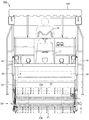
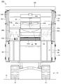
枝豆収穫機100は、図1ないし図3に示すように、走行装置10に、もぎ取り装置20と、搬送コンベア30と、選別装置40と、収容コンテナ50が搭載されている。
As shown in FIGS. 1 to 3, the
走行装置10は、エンジン11により油圧式トランスミッション(図示せず)を介して駆動される左右一対のクローラ12を下フレーム13に備え、左右のクローラ12,12を圃場の1条又は複数条の畝(畝には枝豆1が植え付けられている)に跨がらせて圃場内を畝に沿って走行するようになっている。より具体的には、畝間約1.2m(軌道間)、長さ50〜60mを走行しながら収穫作業する。走行装置10の上フレーム(機体)14の前部には、操縦席15と走行ハンドル16が設置され、走行ハンドル16の前方にはコントロールボックス17が設置されている。コントロールボックス17には、エンジン制御機器及び計器類が装備されている。また、操縦席15の近くには、もぎ取り装置20、搬送コンベア30、選別装置40等の駆動モータの操作レバー、もぎ取り装置20、収容コンテナ50等の作動用油圧シリンダの操作レバー等が設置されている。
The
操縦席15の背後に位置して、上フレーム14の上面には、前述のエンジン11が、枝豆収穫機100の装置全体の略重心位置に搭載されている。したがって、エンジン11は搬送コンベア30の直上に位置している。なお、操縦席15の上方には日差しを遮る天幕15Aが設けられている。
The
もぎ取り装置20は、畝上に植え付けられた枝豆1から枝豆莢2をもぎ取る装置で、枝豆1を掻き込む掻き込みブラシ21と、掻き込まれた枝豆1を後方に案内する案内ローラ22と、後方に案内された枝豆1から枝豆莢2をもぎ取るもぎ取りドラム23と、高さ設定可能で畝上を転動しながらもぎ取りドラム23のもぎ取り高さを一定に保つ高さ調整ローラ24を備えている。
The
掻き込みブラシ21は、もぎ取りカバー25に支持された左右の側板21a,21a間に回転軸21bが軸支され、回転軸21bの周囲に弾性変形可能な多数のブラシ部材21cが全幅にわたり取り付けられている。掻き込みブラシ21は、駆動モータ26により、多数のブラシ部材21cを図1の反時計回りに回転させ、畝上の枝豆1を後方の案内ローラ22へ向けて掻き込むようになっている。案内ローラ22は前後一対のローラ体22a,22aからなり、それぞれ前記側板21a,21a間に回転自在に軸支され、前記駆動モータ26により、チェーンを介して各ローラ体22a,22aを同期して図1の反時計回りに回転させ、掻き込まれた枝豆1を後方のもぎ取りドラム23内へ案内するようになっている。なお、符号21dは圃場上の枝豆1を掻き込みブラシ21側へ寄せるガイドを示している。
The scraping
もぎ取りドラム23は、もぎ取りカバー25の側板25a,25a間に回転軸23aが軸支され、回転軸23aの周囲に一定間隔で多数本のもぎ取り爪23bが全幅にわたり取り付けられている。もぎ取りドラム23は、駆動モータ27により、各もぎ取り爪23bを図1の時計回りに回転させ、案内ローラ22によってもぎ取りドラム23内へ案内された枝豆1から枝豆莢2を効率良くもぎ取るようになっている。各もぎ取り爪23bの先端部は、回転方向を向くように所定の角度屈曲され、もぎ取り効果を高めている。もぎ取りドラム23ともぎ取りカバー25の天板内面との間に、もぎ取られた枝豆莢2を効率よく後方の搬送コンベア30へ送るための送り空間28が設けられている。
In the tearing
もぎ取りカバー25は、走行装置10の左右の下フレーム13に支持軸29aを介して支持された支持部材29と、走行装置10の上フレーム14の前部に連結された油圧シリンダ18とにより浮上姿勢に支持されている。油圧シリンダ18の作動により、もぎ取り装置20全体が上下に位置調整可能とされている。もぎ取りカバー25の前部は、走行装置10の操縦席15付近に連結された油圧式の補助シリンダ19により浮上姿勢が補助されている。もぎ取り装置20の上下位置調整はフロート式とされ、左右の支持部材29の前端に前述の高さ調整ローラ24が連結支持されている。
The
高さ調整ローラ24は、図1および図4に示すように、左右の支持部材29の前端に垂直下向きのシリンダ24aが固定支持されている。また、同シリンダ24aはもぎ取りカバー25の側板25aに固定されている。各シリンダ24a内にはスライド軸24bが収納され、左右のスライド軸24bの下端軸受24c間に回転軸が回転自在に支持された長尺なローラ体24dが幅方向に配置されている。ローラ体24dは左右のスライド軸24b,24b間に延在し、もぎ取り装置20の高さ調整を安定化させている。各シリンダ24a内の上部には、スライド軸24bの上面に当接し、各シリンダ24aの下端から突出するスライド軸24bの突出量を設定するねじ式調整部材24eが配置されている。左右のねじ式調整部材24eは、図示しない歯車を介して水平軸24fと互いに連結されている。したがって、ハンドル操作により水平軸24fを介して左右のねじ式調整部材24eを同時に上下させ、左右のスライド軸24bの突出量を同じレベルに設定することができる。これにより、ハンドル操作により圃場の地面レベルからのもぎ取り装置20のもぎ取り高さを調整・変更できるようになっている。
As shown in FIGS. 1 and 4, the
搬送コンベア30は、もぎ取り装置20でもぎ取られた枝豆莢2と枝葉3を駆動モータ31により後方の選別装置40へ搬送するもので、その前端がもぎ取りカバー25内の下方であって、もぎ取りドラム23の近接位置に位置している。より具体的には、搬送コンベア30の前端の高さはもぎ取りドラム23の回転軸23aの高さと略同一レベルに設定され、また、搬送コンベア30の前端ともぎ取り爪23bの先端との間の水平方向クリアランスは0.5cm〜2cmに設定され、送り空間28における排出口における垂直方向クリアランスは25cm〜35cmに設定されている。
The
また、搬送コンベア30は、操縦席15の下部および上フレーム14上のエンジン11の直下を斜め上向きに通り、その後端が後方の収容コンテナ50よりも上方位置まで延在している。搬送コンベア30の地面に対する傾斜角度は25度〜35度に設定されている。搬送コンベア30は、桟付きベルトコンベアを主体とし、左右の側部フレーム32の後端の駆動ローラ33aおよび前端の従動ローラ33b間に搬送ベルト34が巻回されている。そして、駆動モータ31によりチェーンを介して駆動ローラ33aを図1の時計回りに回転させて、搬送ベルト34上に枝豆莢2と枝葉3を載せて後方の選別装置40へ搬送するようになっている。
Further, the
搬送コンベア30の前端部は、左右の支持部材29の前端部に軸受29bおよび連結軸29cを介して回動可能に連結されている。搬送コンベア30の後端部は、上フレーム14の左右の後部支柱14Aの内側面に取り付けられたガイド部35により搬送コンベア30の延在方向に沿ってスライド可能に支持されている。ガイド部35は、図1および図6に示すように、上フレーム14の各後部支柱14Aの内側面に搬送コンベア30の延在方向に沿って取り付けられた断面L字形のガイド片35Aのガイド面35a上を、搬送コンベア30の側部フレーム32の側面に回転自在に取付けられたガイドローラ35Bが接地し、転動することにより、搬送コンベア30の後端部をガイド部35に支持させると共に、もぎ取り装置20の動きとともに昇降する搬送コンベア30の前端部の動きにあわせて、搬送コンベア30をその延在方向に沿って後方または前方にスライドさせるようになっている。
The front end portion of the
選別装置40は、搬送ベルト34上を搬送された枝豆莢2と枝葉3を左右および前後に均等にならす均し装置41と、搬送ベルト34の後端から落下した枝豆莢2と枝葉3を幅方向中央に寄せるスクリューコンベア42と、寄せられた枝豆莢2と枝葉3を選別する篩コンベア43と、枝豆莢2と枝葉3を風選別する風選ファン44を備えている。
The sorting
均し装置41は、図1および図5に示すように、上フレーム14の左右の後部支柱14Aに取り付けられたブラケット41a間に回転軸41bが軸支され、回転軸41bの周囲に複数の爪41cが軸方向に疎に取り付けられている。そして、駆動モータ41dによって複数の爪41cを図1の時計回りに回転させ、搬送ベルト34上の枝豆莢2と枝葉3を均等に均すようになっている。各ブラケット41aは均し高さ調整ネジ41eを介して後部支柱14Aに取り付けられ、搬送ベルト34に合せて均し装置41の高さを調整できるようになっている。
As shown in FIGS. 1 and 5, the leveling
スクリューコンベア42は、図1および図5に示すように、収容コンテナ50のフレーム51の上面に設置された上カバー52の側板内面に駆動軸42aが軸支され、駆動軸42aの中央部を除く左右側部に、ねじれ方向が互いに逆向きとなるスクリュー羽根42b,42cが取付けられている。そして、駆動モータ42dによって駆動軸42aを回転駆動させ、回転するスクリュー羽根42b,42cによって、落下した枝豆莢2と枝葉3を中央部に寄せるようになっている。スクリューコンベア42は、篩コンベア43の幅に相当する分だけ中央部が開口しており、中央部から篩コンベア43上に枝豆莢2と枝葉3を落下させるようになっている。
As shown in FIGS. 1 and 5, the
篩コンベア43は、図1に示すように、上カバー52の内部でスクリューコンベア42と収容コンテナ50の上面開口部の間に位置し、上カバー52の側面内面の後部付近および前部付近に駆動軸43aおよび従動軸43bが軸支され、駆動軸43aおよび従動軸43bの各スプロケットに駆動チェーン43cが巻回されている(図1では理解しやすくするため上カバー52内部の篩コンベア43を実線で描いている)。駆動チェーン43cには一定間隔(5cm〜10cm)で複数のロッド棒43dが係止されている。そして、駆動モータ43eにより駆動チェーン43cを駆動させ、落下した枝豆莢2と枝葉3のうち、枝豆莢2は隣接するロッド棒43d,43d間の隙間から収容コンテナ50内に落下させ、枝葉3のみを篩コンベア43上に残し、これにより、篩コンベア43上に落下した枝豆莢2と枝葉3を選別するようになっている。
As shown in FIG. 1, the
風選ファン44は、収容コンテナ50の上カバー52の天面に設けられた吸引口52aの周囲にケーシング44aが設置され、ケーシング44a内にファン本体44bが配置されている。ケーシング44aの上面開口部には排出カバー45が設けられ、排出カバー45の側面に枝葉3の排出口45aが設けられている。そして、駆動モータ44cによってファン本体44bを回転させ、搬送コンベア30の後端からスクリューコンベア42、さらに篩コンベア43上に落下する枝豆莢2と枝葉3のうち、軽量な枝葉3を吸引して、排出カバー45の排出口45aから圃場の地面Gに排出するようになっている。また、篩コンベア43上に落下した枝葉3に吸引力を作用させ、篩コンベア43上を搬送される枝葉3を吸引し、同様に排出カバー45の排出口45aから排出するようになっている。これにより、枝豆莢2と枝葉3を風選別し、篩コンベア43による選別とあわせて、枝豆莢2と枝葉3の選別効率を高めている。なお、風選ファン44により分離されなかった枝葉3は、篩コンベア43上を後方へ搬送され、圃場の地面Gへ排出されるようになっている。
In the wind-
収容コンテナ50は、選別された枝豆莢2を収容するもので、左右の後部支柱14Aに連結された4点リンク式の平行アーム53,53と油圧シリンダ54によりフレーム51を介して支持されており、油圧シリンダ54の駆動により、下方の収容位置(図1の矢印L)から上方の排出位置(図1の矢印H)までの最適位置に設定することができる。収容コンテナ50の底板50aは、前後に2分割され、小型の油圧シリンダ55の駆動により、下方の収容位置では底板50aを閉口し、上方の排出位置では底板50aを開口することができる。
The
収容コンテナ50内の枝豆莢2は、上方の排出位置から底板50aを開口することにより、その直下の運搬車(図示せず)に移し替えられ、出荷工場に運ばれる。
The
次に、上記構成の枝豆収穫機100を用いて、圃場内に植え付けられている枝豆1の収穫方法について説明する。
Next, a method for harvesting
まず、畝を跨るように枝豆収穫機100を位置決めし、コントロールボックス17上の操作により、エンジン11を始動し、合わせて、もぎ取り装置20、搬送コンベア30、選別装置40を作動させる。作動状態からエンジン11の駆動力を左右のクローラ12に伝達し、低速走行させる。
First, the
枝豆収穫機100の走行中、先頭に位置する掻き込みブラシ21が回転しながら、畝上の枝豆1を後方に掻き込むと共に、掻き込まれた枝豆1を回転する案内ローラ22が後方のもぎ取りドラム23へ案内し、回転するもぎ取り爪23bが枝豆1から枝豆莢2をもぎ取る。もぎ取られた、枝葉3の混入した枝豆莢2はもぎ取りカバー25内の送り空間28内を後方の搬送コンベア30へ向けて送られる。
While the green
枝豆収穫機100の走行中、畝の地面Gの高低に追従して、支持部材29の支持軸29aを回動点として、もぎ取りドラム23が昇降する。すなわち、枝豆収穫機100の走行中、畝の地面Gの高さに高低があると、地面に追従して高さ調整ローラ24が昇降し、高さ調整ローラ24と一体なもぎ取りドラム23も連動して昇降する。これにより、枝豆収穫機100の走行中、畝の地面Gの高さに高低があっても、畝の地面Gからのもぎ取り高さが常に一定に保たれる。これにより、枝豆収穫機100の走行中、畝の地面G上に上下のうねりがあっても、常に畝上の枝豆1から枝豆莢2を確実にもぎ取ることができる。
While the green
また、搬送コンベア30の前端部が支持部材29の前端部に軸受29bおよび連結軸29cを介して連結されているので、高さ調整ローラ24の昇降に連動して搬送コンベア30の前端部も昇降する。これにより、畝の地面Gの高低に追従して、もぎ取りドラム23が昇降しても、搬送コンベア30の前端部が連動して昇降するから、もぎ取りドラム23と搬送コンベア30の前端部の間のクリアランスが安定し、もぎ取りドラム23から排出された枝豆莢2の落下高さが安定し、搬送コンベア30の前端部に落下した枝豆莢2が前方へ向けて転がり前端から落下することなく、確実に後方へ向けて搬送される。
Further, since the front end portion of the
搬送コンベア30の搬送ベルト34上を後方へ搬送される枝豆莢2および枝葉3は、搬送コンベア30の後端部付近に配置された均し装置41の回転する爪41cにより均等に均され、搬送コンベア30の後端からスクリューコンベア42の上に落下し、回転する左右のスクリュー羽根42b,42cにより開口する中央部に寄せられ、中央部から篩コンベア43上に落下させられる。
The
搬送コンベア30の後端から篩コンベア43上に落下する枝豆莢2と枝葉3のうち、軽量な大部分の枝葉3は、風選ファン44の駆動により上カバー52内の吸引口52aから排出カバー45内に吸引され、排出口45aから圃場の地面Gに排出される。篩コンベア43上に落下した枝豆莢2はロッド棒43d,43dの隙間から収容コンテナ50内に落下する。篩コンベア43上に落下した残りの枝葉3は、一部が風選ファン44により吸引され、排出カバー45の排出口45aから圃場の地面Gに排出され、吸引されずに篩コンベア43のロッド棒43dに引っ掛かった枝葉3は篩コンベア43上を後方へ搬送され、圃場の地面Gへ排出される。これにより、枝豆莢2と枝葉3は選別され、重量のある枝豆莢2は収容コンテナ50内にことごとく収容される。
Of the
収容コンテナ50内が選別された枝豆莢2で一杯になったら、収容コンテナ50を上方排出位置Hに持ち上げて、圃場に横付けあるいは後付けされた搬送車に対し、収容コンテナ50の底板50aを開口して内部の枝豆莢2を移し替え、次の収穫作業に移る。収容袋などに枝豆莢2を載せた搬送車は、出荷工場等に移動し、収穫された枝豆莢2は新鮮なうちに出荷される。
When the inside of the
枝豆収穫機100によれば、次の作用効果が得られる。
According to the
(1)走行時に、畝の地面Gの高低に追従して昇降するもぎ取りドラム23に連動して、搬送コンベア30の前端も昇降するから、もぎ取りドラム23から排出された枝豆莢2を搬送コンベア30が確実に受け取ることができる。これにより枝豆莢2の取りこぼしを減らし、枝豆莢2の収穫損失を減らし、収穫効率を向上させることができる。
(1) When traveling, the front end of the
(2)搬送コンベア30の後端部は、搬送コンベア30の前端の昇降動作に追従してガイド部35によりスライド可能とされているから、搬送コンベア30の前端の昇降動作を円滑な動きとすることができる。したがって、走行時に、畝の地面Gの高低に追従するもぎ取りドラム23の昇降動作も円滑な動きとすることができ、これによって、もぎ取りドラム23によるもぎ取り作業が安定する。
(2) Since the rear end portion of the
(3)エンジン11を搬送コンベア30の上方に配置したので、エンジン11からの排熱が搬送コンベア30上を搬送される新鮮な枝豆莢2に与える影響を極力減らすことができる。また、走行時にエンジン11に地面からの土埃が入ることを防ぎ、エンジン11の耐久性を向上させることができる。さらに、エンジン11が収穫機全体の略重心位置に搭載されているから、走行安定性が向上し、畝上の枝豆1のもぎ取り作業が安定する。これらの作用によっても、枝豆莢2の取りこぼしが低減する。
(3) Since the
(4)風選ファン44により、搬送コンベア30の後端から落下する枝葉3や篩コンベア43上に落下した枝葉3を効率よく吸引し、枝豆莢2と枝葉3を効率よく選別することができる。また、風選ファン44により吸引されなかった枝葉3を、篩コンベア43により枝豆莢2と確実に選別することができる。したがって、収容コンベア50内に落下する枝葉3が極力排除される。
(4) The branching leaf 3 falling from the rear end of the
(5)枝豆収穫機100を用いることにより、栽培規模の大きい圃場であっても、短時間で効率よく枝豆莢2の収穫作業が行える。また、収穫と同時に枝豆莢2と枝葉3の選別作業を精度良く行える。これにより、後行程での選別作業が大幅に減り、収穫作業者の大幅な労力軽減と省力化が図れる。また、新鮮なうちに枝豆莢2を出荷できる。
(5) By using the
(6)枝豆収穫機100を用いることにより、枝豆莢2の取りこぼしが極力減り、枝豆莢2の収穫率が上がり、歩留まりが大幅に改善された。
(6) By using the
本発明に係る枝豆収穫機は、前記実施形態で説明した枝豆収穫機100の構造に限定されない。もぎ取り装置20の前方に夾雑物除去装置をオプションとして備えてよい。枝豆1をもぎ取る前に、予め夾雑物(枝豆莢2の存在しない上部の枝葉部分)を除去することで、枝豆莢2と枝葉3の選別をよりやり易くする。また、回動点(連結軸29c)を中心とする搬送コンベア30の前端部の昇降に併せて搬送コンベア30の後端部側をスライドさせる機構は、搬送コンベア30の後端部を後部支柱14A等からスライド可能に支持するリンク機構であってもよい。
The green soybean harvester according to the present invention is not limited to the structure of the
搬送コンベアは、もぎ取り装置の昇降動作に合せて、前端が昇降する構造に限られない。もぎ取り装置の昇降動作に合せて、搬送コンベア全体が昇降する構造や昇降コンベアの前半部が昇降する構造であってもよい。 The conveyor is not limited to a structure in which the front end is raised and lowered in accordance with the raising and lowering operation of the demolition device. A structure in which the entire transport conveyor moves up and down or a structure in which the first half of the lifting conveyor moves up and down may be used in accordance with the lifting operation of the demolition device.
本発明に係る枝豆収穫機は、前記実施形態で説明した乗用型の枝豆収穫機に限定されない。本発明を小型の一畝用の歩行型収穫機などにも広く適用可能である。 The green soybean harvester according to the present invention is not limited to the riding-type green soybean harvester described in the above embodiment. The present invention can be widely applied to a small-sized walk-type harvester for a glance.
本発明は、枝豆収穫作業に用いる機械として、乗用型、歩行型のタイプの他、もぎ取りおよび選別を行う農作物の収穫作業機としても利用可能である。 INDUSTRIAL APPLICABILITY The present invention can be used as a harvesting machine for crops for picking and sorting as well as a riding type and a walking type as a machine used for green soybean harvesting.
1 枝豆
2 枝豆莢
3 枝葉
10 走行装置
11 エンジン
12 クローラ
13 下フレーム
14 上フレーム
14A 後部支柱
15 操縦席
16 走行ハンドル
17 コントロールボックス
18,54,55 油圧シリンダ
19 補助シリンダ
20 もぎ取り装置
21 掻き込みブラシ
21a,25a 側板
21b,23a,24d,41b 回転軸
21c ブラシ部材
22 案内ローラ
22a,24d ローラ体
23 もぎ取りドラム
23b もぎ取り爪
24 高さ調整ローラ
24a シリンダ
24b スライド軸
24c,29b 軸受
24e ねじ棒式調整部材
24f 水平軸
25 もぎ取りカバー
26,27,31,41d,42e,44c 駆動モータ
28 送り空間
29 支持部材
29a 支持軸
29c 連結軸
30 搬送コンベア
32 側部フレーム
33a 駆動ローラ
33b 従動ローラ
34 搬送ベルト
34a,43c 駆動チェーン
35 ガイド部
35A ガイド片
35a ガイド面
35B ガイドローラ
40 選別装置
41 均し装置
41a ブラケット
41c 爪
41e 均し高さ調整ネジ
42 スクリューコンベア
42a,43a 駆動軸
42b,42c スクリュー羽根
43 篩コンベア
43b 従動軸
43d ロッド棒
44 風選ファン
44a ケーシング
44b ファン本体
45 排出カバー
45a 排出口
50 収容コンテナ
50a 底板
51 フレーム
52 上カバー
52a 吸引口
53 平行アーム
100 枝豆収穫機
G 圃場の地面
DESCRIPTION OF
Claims (11)
枝豆が植えられている地面に追従して昇降し、前記枝豆から枝豆莢をもぎ取るもぎ取り装置と、もぎ取られた枝豆莢を搬送する搬送コンベアと、枝豆莢を収容する収容コンテナを備え、
前記搬送コンベアは、もぎ取り装置の昇降動作に合わせて昇降するように走行装置または機体に支持されていることを特徴とする枝豆収穫機。 In a harvesting machine that harvests green soybeans cultivated in the field while traveling with a traveling device,
Follow the ground where the green soybeans are planted, elevate and tear off the green soybean beans from the green soybeans, a transport conveyor that conveys the green soybean balls, and a storage container that stores the green soybean beans,
The green soybean harvesting machine, wherein the conveyor is supported by a traveling device or a machine body so as to move up and down in accordance with a lifting operation of the demolition device.
Priority Applications (1)
| Application Number | Priority Date | Filing Date | Title |
|---|---|---|---|
| JP2012145345A JP6006020B2 (en) | 2012-06-28 | 2012-06-28 | Green soybean harvesting machine |
Applications Claiming Priority (1)
| Application Number | Priority Date | Filing Date | Title |
|---|---|---|---|
| JP2012145345A JP6006020B2 (en) | 2012-06-28 | 2012-06-28 | Green soybean harvesting machine |
Publications (2)
| Publication Number | Publication Date |
|---|---|
| JP2014007973A true JP2014007973A (en) | 2014-01-20 |
| JP6006020B2 JP6006020B2 (en) | 2016-10-12 |
Family
ID=50105230
Family Applications (1)
| Application Number | Title | Priority Date | Filing Date |
|---|---|---|---|
| JP2012145345A Active JP6006020B2 (en) | 2012-06-28 | 2012-06-28 | Green soybean harvesting machine |
Country Status (1)
| Country | Link |
|---|---|
| JP (1) | JP6006020B2 (en) |
Cited By (5)
| Publication number | Priority date | Publication date | Assignee | Title |
|---|---|---|---|---|
| CN104798534A (en) * | 2015-05-09 | 2015-07-29 | 喻凤莲 | Multifunctional green soy bean picking machine |
| CN108925229A (en) * | 2018-08-02 | 2018-12-04 | 农业部南京农业机械化研究所 | A kind of bean picking machine of suitable single furrow multiple row planting |
| CN109392439A (en) * | 2018-12-24 | 2019-03-01 | 宁波海通时代农业有限公司 | The green soy bean automatic separating apparatus of green soy bean harvester |
| CN111247949A (en) * | 2020-03-19 | 2020-06-09 | 南通东威环保设备有限公司 | Small self-propelled green soybean picking machine |
| CN112930861A (en) * | 2021-03-02 | 2021-06-11 | 金华市农业科学研究院(浙江省农业机械研究院) | Green soy bean picking mechanism |
Citations (7)
| Publication number | Priority date | Publication date | Assignee | Title |
|---|---|---|---|---|
| JPS5754523A (en) * | 1980-09-18 | 1982-04-01 | Iseki Agricult Mach | Reaper in soy bean reaper and thresher |
| JPS5936018A (en) * | 1982-08-20 | 1984-02-28 | Iseki & Co Ltd | Long vegetable aligning apparatus |
| JPH06169628A (en) * | 1992-12-02 | 1994-06-21 | Iseki & Co Ltd | Interfurrow regulator of bean reaper |
| JPH07135831A (en) * | 1993-11-19 | 1995-05-30 | Seirei Ind Co Ltd | Harvester for leaf vegetable without forming head |
| JP2004008222A (en) * | 2003-09-24 | 2004-01-15 | Seirei Ind Co Ltd | Harvester for drawing out unmatured soybean |
| JP2006254719A (en) * | 2005-03-15 | 2006-09-28 | Mitsuwa:Kk | Green soybean harvester |
| JP2011024514A (en) * | 2009-07-28 | 2011-02-10 | Matsumoto Kiko Kk | Green soybean harvester |
-
2012
- 2012-06-28 JP JP2012145345A patent/JP6006020B2/en active Active
Patent Citations (7)
| Publication number | Priority date | Publication date | Assignee | Title |
|---|---|---|---|---|
| JPS5754523A (en) * | 1980-09-18 | 1982-04-01 | Iseki Agricult Mach | Reaper in soy bean reaper and thresher |
| JPS5936018A (en) * | 1982-08-20 | 1984-02-28 | Iseki & Co Ltd | Long vegetable aligning apparatus |
| JPH06169628A (en) * | 1992-12-02 | 1994-06-21 | Iseki & Co Ltd | Interfurrow regulator of bean reaper |
| JPH07135831A (en) * | 1993-11-19 | 1995-05-30 | Seirei Ind Co Ltd | Harvester for leaf vegetable without forming head |
| JP2004008222A (en) * | 2003-09-24 | 2004-01-15 | Seirei Ind Co Ltd | Harvester for drawing out unmatured soybean |
| JP2006254719A (en) * | 2005-03-15 | 2006-09-28 | Mitsuwa:Kk | Green soybean harvester |
| JP2011024514A (en) * | 2009-07-28 | 2011-02-10 | Matsumoto Kiko Kk | Green soybean harvester |
Cited By (5)
| Publication number | Priority date | Publication date | Assignee | Title |
|---|---|---|---|---|
| CN104798534A (en) * | 2015-05-09 | 2015-07-29 | 喻凤莲 | Multifunctional green soy bean picking machine |
| CN108925229A (en) * | 2018-08-02 | 2018-12-04 | 农业部南京农业机械化研究所 | A kind of bean picking machine of suitable single furrow multiple row planting |
| CN109392439A (en) * | 2018-12-24 | 2019-03-01 | 宁波海通时代农业有限公司 | The green soy bean automatic separating apparatus of green soy bean harvester |
| CN111247949A (en) * | 2020-03-19 | 2020-06-09 | 南通东威环保设备有限公司 | Small self-propelled green soybean picking machine |
| CN112930861A (en) * | 2021-03-02 | 2021-06-11 | 金华市农业科学研究院(浙江省农业机械研究院) | Green soy bean picking mechanism |
Also Published As
| Publication number | Publication date |
|---|---|
| JP6006020B2 (en) | 2016-10-12 |
Similar Documents
| Publication | Publication Date | Title |
|---|---|---|
| JP5448053B2 (en) | Green soybean harvesting machine | |
| JP6006020B2 (en) | Green soybean harvesting machine | |
| KR101669721B1 (en) | Tractor trailed type welsh onion harvester | |
| CN103039175B (en) | Two ridge four lines feed peanut combine entirely | |
| US20090165433A1 (en) | Method and Apparatus for Harvesting Standing Vegetable Crops | |
| CN103348816A (en) | Green soybean harvesting machine | |
| JP2009261348A (en) | Vegetable harvester | |
| JP4934581B2 (en) | Leaf vegetable harvesting machine | |
| JP5050427B2 (en) | Foliage harvesting machine | |
| JP5476698B2 (en) | Crop separation harvester | |
| JP2015181389A (en) | corn harvester | |
| JP4612498B2 (en) | Harvesting structure of harvesting machine | |
| JP2009106252A (en) | Combine harvester | |
| CN203369117U (en) | Green soy bean harvester | |
| JP6208960B2 (en) | Tomato harvester | |
| JP2015181390A (en) | corn harvester | |
| JP2009171902A (en) | Crop separating harvester | |
| MXGT05000009A (en) | Vegetable harvesting machine with a container and a discharge system. | |
| CN203057850U (en) | Two-ridge four-row whole-feeding peanut combined harvester | |
| JP5470722B2 (en) | Root crop harvesting machine | |
| JP2007252259A (en) | Harvester | |
| JP5066903B2 (en) | Harvesting machine | |
| JP5059578B2 (en) | Leaf vegetable harvesting machine | |
| JP2016116474A (en) | Corn harvester | |
| JP2009044991A (en) | Combine harvester |
Legal Events
| Date | Code | Title | Description |
|---|---|---|---|
| A621 | Written request for application examination |
Free format text: JAPANESE INTERMEDIATE CODE: A621 Effective date: 20150529 |
|
| A977 | Report on retrieval |
Free format text: JAPANESE INTERMEDIATE CODE: A971007 Effective date: 20160303 |
|
| A131 | Notification of reasons for refusal |
Free format text: JAPANESE INTERMEDIATE CODE: A131 Effective date: 20160307 |
|
| A521 | Request for written amendment filed |
Free format text: JAPANESE INTERMEDIATE CODE: A523 Effective date: 20160413 |
|
| TRDD | Decision of grant or rejection written | ||
| A01 | Written decision to grant a patent or to grant a registration (utility model) |
Free format text: JAPANESE INTERMEDIATE CODE: A01 Effective date: 20160902 |
|
| A61 | First payment of annual fees (during grant procedure) |
Free format text: JAPANESE INTERMEDIATE CODE: A61 Effective date: 20160908 |
|
| R150 | Certificate of patent or registration of utility model |
Ref document number: 6006020 Country of ref document: JP Free format text: JAPANESE INTERMEDIATE CODE: R150 |
|
| R250 | Receipt of annual fees |
Free format text: JAPANESE INTERMEDIATE CODE: R250 |
|
| R250 | Receipt of annual fees |
Free format text: JAPANESE INTERMEDIATE CODE: R250 |
|
| R250 | Receipt of annual fees |
Free format text: JAPANESE INTERMEDIATE CODE: R250 |
|
| R250 | Receipt of annual fees |
Free format text: JAPANESE INTERMEDIATE CODE: R250 |
|
| R250 | Receipt of annual fees |
Free format text: JAPANESE INTERMEDIATE CODE: R250 |