JP2013544602A - Beverage preparation machine with automatic washing system - Google Patents
Beverage preparation machine with automatic washing system Download PDFInfo
- Publication number
- JP2013544602A JP2013544602A JP2013541383A JP2013541383A JP2013544602A JP 2013544602 A JP2013544602 A JP 2013544602A JP 2013541383 A JP2013541383 A JP 2013541383A JP 2013541383 A JP2013541383 A JP 2013541383A JP 2013544602 A JP2013544602 A JP 2013544602A
- Authority
- JP
- Japan
- Prior art keywords
- channel
- beverage preparation
- liquid
- internal
- machine
- Prior art date
- Legal status (The legal status is an assumption and is not a legal conclusion. Google has not performed a legal analysis and makes no representation as to the accuracy of the status listed.)
- Pending
Links
Images


Classifications
-
- A—HUMAN NECESSITIES
- A47—FURNITURE; DOMESTIC ARTICLES OR APPLIANCES; COFFEE MILLS; SPICE MILLS; SUCTION CLEANERS IN GENERAL
- A47J—KITCHEN EQUIPMENT; COFFEE MILLS; SPICE MILLS; APPARATUS FOR MAKING BEVERAGES
- A47J31/00—Apparatus for making beverages
- A47J31/44—Parts or details or accessories of beverage-making apparatus
- A47J31/60—Cleaning devices
-
- A—HUMAN NECESSITIES
- A47—FURNITURE; DOMESTIC ARTICLES OR APPLIANCES; COFFEE MILLS; SPICE MILLS; SUCTION CLEANERS IN GENERAL
- A47J—KITCHEN EQUIPMENT; COFFEE MILLS; SPICE MILLS; APPARATUS FOR MAKING BEVERAGES
- A47J31/00—Apparatus for making beverages
- A47J31/24—Coffee-making apparatus in which hot water is passed through the filter under pressure, i.e. in which the coffee grounds are extracted under pressure
- A47J31/34—Coffee-making apparatus in which hot water is passed through the filter under pressure, i.e. in which the coffee grounds are extracted under pressure with hot water under liquid pressure
- A47J31/36—Coffee-making apparatus in which hot water is passed through the filter under pressure, i.e. in which the coffee grounds are extracted under pressure with hot water under liquid pressure with mechanical pressure-producing means
- A47J31/3666—Coffee-making apparatus in which hot water is passed through the filter under pressure, i.e. in which the coffee grounds are extracted under pressure with hot water under liquid pressure with mechanical pressure-producing means whereby the loading of the brewing chamber with the brewing material is performed by the user
- A47J31/3676—Cartridges being employed
- A47J31/369—Impermeable cartridges being employed
- A47J31/3695—Cartridge perforating means for creating the hot water inlet
-
- B—PERFORMING OPERATIONS; TRANSPORTING
- B08—CLEANING
- B08B—CLEANING IN GENERAL; PREVENTION OF FOULING IN GENERAL
- B08B9/00—Cleaning hollow articles by methods or apparatus specially adapted thereto
- B08B9/02—Cleaning pipes or tubes or systems of pipes or tubes
- B08B9/027—Cleaning the internal surfaces; Removal of blockages
- B08B9/04—Cleaning the internal surfaces; Removal of blockages using cleaning devices introduced into and moved along the pipes
- B08B9/043—Cleaning the internal surfaces; Removal of blockages using cleaning devices introduced into and moved along the pipes moved by externally powered mechanical linkage, e.g. pushed or drawn through the pipes
- B08B9/0436—Cleaning the internal surfaces; Removal of blockages using cleaning devices introduced into and moved along the pipes moved by externally powered mechanical linkage, e.g. pushed or drawn through the pipes provided with mechanical cleaning tools, e.g. scrapers, with or without additional fluid jets
Landscapes
- Engineering & Computer Science (AREA)
- Food Science & Technology (AREA)
- Mechanical Engineering (AREA)
- Apparatus For Making Beverages (AREA)
- Devices For Dispensing Beverages (AREA)
- Beverage Vending Machines With Cups, And Gas Or Electricity Vending Machines (AREA)
Abstract
本発明は、原材料カプセルへの液体の注入によって飲料を調製するための飲料調製システム(1)であって、原材料カプセル(54)および飲料調製マシン(2、200)を備え、該飲料調製マシン(2、200)が、液体を原材料カプセルに注入するための少なくとも1つの内部貫通チャネル(75、210)を有する注入ユニット(73、204)と、マシンに飲料を調製させるための作動手段とを有する飲料調製システム(1)において、マシンが、前記少なくとも1つの内部貫通チャネルを自動的に洗浄するための洗浄装置(90、220)をさらに備え、該洗浄装置が、前記作動手段によって駆動されることを特徴とする飲料調製システム(1)に関する。
【選択図】 図5The present invention is a beverage preparation system (1) for preparing a beverage by injecting a liquid into a raw material capsule, comprising a raw material capsule (54) and a beverage preparation machine (2, 200), the beverage preparation machine ( 2, 200) has an injection unit (73, 204) having at least one internal through channel (75, 210) for injecting liquid into the raw material capsule and an actuating means for causing the machine to prepare the beverage In the beverage preparation system (1), the machine further comprises a cleaning device (90, 220) for automatically cleaning the at least one internal penetration channel, the cleaning device being driven by the actuating means The present invention relates to a beverage preparation system (1).
[Selection] Figure 5
Description
本発明は、原材料カプセル内への液体の注入によって飲料を調製するための飲料調製マシンを含む飲料システムに関する。 The present invention relates to a beverage system comprising a beverage preparation machine for preparing a beverage by injection of liquid into a raw material capsule.
原材料カプセルは、飲料の調整、ほとんどの場合は液体食品の調製をするための液体の添加によって使用される食品の原材料または物質を含む。 Raw material capsules contain food raw materials or substances used by the preparation of beverages, most often by the addition of liquids to make liquid foods.
飲料調製マシンは、流体、好ましくは、水などの液体を前記カプセル内に圧力下で注入するための流体注入システム、および、カプセルを収容するための受容体を備える。例えば、コーヒー飲料の調製のために、カプセル内へ圧力下で注入される水は、温かいこと、すなわち、70℃より高い温度であることが好ましい。しかしながら、いくつかの特定の例では、水は周囲温度であってもよい。カプセル原材料の抽出および/または溶解中のカプセルの内部の圧力は、一般に、溶解生成物に関しては約1〜6バールであり、焙煎して挽いたコーヒーの抽出に関しては2〜12バールである。このような調製工程は、淹出には流体(例えば、温水)による原材料の長時間の浸出が必要とされる一方で、飲料調製工程は、消費者による数秒以内の飲料(例えば、コーヒー)の調製を可能にするという点で、飲料調製のいわゆる「淹出」工程(特に茶およびコーヒーの)とは大きく異なっている。 The beverage preparation machine comprises a fluid injection system for injecting a fluid, preferably a liquid such as water, into the capsule under pressure, and a receiver for containing the capsule. For example, for the preparation of a coffee beverage, it is preferred that the water injected under pressure into the capsule is warm, i.e. above 70 ° C. However, in some specific examples, the water may be at ambient temperature. The pressure inside the capsule during the extraction and / or dissolution of the capsule raw material is generally about 1-6 bar for the dissolved product and 2-12 bar for the extraction of roast and ground coffee. While such a preparation process requires long-term leaching of the raw material with a fluid (eg, hot water) for brewing, the beverage preparation process requires a beverage (eg, coffee) within a few seconds by the consumer. It is very different from the so-called “brewing” process of beverage preparation (especially for tea and coffee) in that it allows preparation.
閉鎖されたカプセルの原材料の抽出および/または溶解を圧力下で行う原理は、周知であり、一般に、カプセルをマシンの受容体内に挿置すること、原材料の抽出または溶解のいずれかを行うためにカプセル内部を加圧環境にするために任意の量の加圧水をカプセル内に注入すること、および、次に、カプセル中の抽出された原材料または溶解された原材料を放出することからなる。このタイプのカプセルについては、例えば、本出願人の欧州特許第1472156号明細書および欧州特許第1784344号明細書において既に記載されている。 The principle of extracting and / or dissolving raw material of a closed capsule under pressure is well known, generally to place the capsule into the machine's receptacle, either to extract or dissolve the raw material Injecting any amount of pressurized water into the capsule to make the capsule interior a pressurized environment, and then releasing the extracted or dissolved raw material in the capsule. This type of capsule has already been described, for example, in the applicants EP 1472156 and EP 1784344.
この原理に従って動作するマシンについては、例えば、スイス国特許第605293号明細書および欧州特許第242556号明細書において既に記載されている。これらの文書によれば、飲料調製マシンは、その先端領域に1つ以上の液体注入オリフィスを備える中空針の形態に作製された穿孔・注入部品、および、カプセルを収容するための受容体を備える。中空針は、一方では、カプセルの上部を穿孔して、その結果、これを開き、他方では、水が、カプセル内に注入されるように、先端領域を介してカプセルまで流れることを可能にする貫通入口チャネルが、針の内部に形成されているという点で、二重の機能を有する。 Machines operating according to this principle have already been described, for example, in Swiss Patent No. 605,293 and European Patent No. 242556. According to these documents, the beverage preparation machine comprises a perforation / infusion part made in the form of a hollow needle with one or more liquid injection orifices in its tip region, and a receiver for receiving the capsules. . The hollow needle, on the one hand, punctures the top of the capsule and consequently opens it, on the other hand, allows water to flow through the tip region to the capsule so that it can be injected into the capsule. The penetration channel has a dual function in that it is formed inside the needle.
調製される飲料が、コーヒーである場合、カプセルは、カプセル内に注入される温水によって抽出されるべきである焙煎して挽いたコーヒー粉末を原材料として含んでもよい。 If the beverage to be prepared is coffee, the capsule may contain as raw material a roast and ground coffee powder that should be extracted by hot water injected into the capsule.
このような用途のためのカプセルが、開発されてきており、これは、本出願人の欧州特許第1784344号明細書および欧州特許出願公開第2062831号明細書において開示されている。 Capsules for such applications have been developed and are disclosed in the Applicant's EP 1784344 and EP-A-2062831.
簡単に述べると、このタイプのカプセルは、一般に、
中空本体、および、注入壁(液体および空気を通さず、カプセルの上端において該本体に取り付けられ、例えばマシンの注入針によって穿刺されるように構成される)と、
抽出される焙煎して挽いたコーヒーのベッド(層)を含むチャンバと、
前記カプセルを閉鎖し、チャンバの内部圧力を維持するためにカプセルの底端に配置されたアルミニウム膜であって、チャンバの前記内部圧力が特定の所定の値に達したときに、膜に投与孔を形成するための穿孔手段と関連付けられているアルミニウム膜と、
随意的ではあるが、カプセルに注入される水の噴流の速度を低下させるために水の噴流を遮断し、低下した速度で物質のベッドの全体にわたって水を供給するために構成された手段と
を備える。
Simply put, this type of capsule is generally
A hollow body, and an infusion wall (impervious to liquid and air, attached to the body at the top of the capsule and configured to be pierced by, for example, an infusion needle of a machine);
A chamber containing a bed of roasted and ground coffee to be extracted;
An aluminum membrane disposed at the bottom end of the capsule to close the capsule and maintain the internal pressure of the chamber, the dosing hole in the membrane when the internal pressure of the chamber reaches a certain predetermined value An aluminum film associated with the perforation means to form
Optionally, means configured to block the water jet to reduce the speed of the water jet injected into the capsule and to supply water throughout the bed of matter at the reduced speed; Prepare.
上述した種類の飲料調製マシンにおいて、抽出流体として水が使用されるとき、スケール付着物(scaling deposits)が、水供給システム(water circulation system)である、水と接触するマシンの部分に形成される。 In beverage preparation machines of the type described above, when water is used as the extraction fluid, scaling deposits are formed in the part of the machine that contacts the water, which is a water circulation system. .
これらのスケール付着物は、マシンの使用とともに経時的に、水供給システムの部分に蓄積する。 These scale deposits accumulate in parts of the water supply system over time as the machine is used.
このことによって、水を穿孔されたカプセルに注入するために使用される、針の貫通入口チャネルが、時間とともに目詰まりする可能性がある。 This can lead to clogging of the needle penetration channel, which is used to inject water into the pierced capsule, over time.
これらのマシンの使用者は、システム、具体的には、針の目詰まりを回避するために、スケール除去製品または抗スケール製品(a descaling or anti−scaling product)を用いて、水供給システムを定期的に洗浄することが求められる。 Users of these machines regularly use a water supply system with a descaling or anti-scaling product to avoid needle clogging. Cleaning is required.
しかしながら、針の内部のチャネルの直径が狭い場合、このことは、特に、スケール形成にとって都合が良い。 However, this is particularly convenient for scale formation when the diameter of the channel inside the needle is narrow.
この問題に対処するために、既存のマシンは、ピン形状部材の形態をした洗浄器具を備えている。 To address this problem, existing machines are equipped with a cleaning implement in the form of a pin-shaped member.
このピン形状部材は、機械公差を考慮しつつ、針のチャネルの内径に対応する外径を有する。 The pin-shaped member has an outer diameter corresponding to the inner diameter of the needle channel, taking into account mechanical tolerances.
マシンの利用者ガイドは、スケール形成、したがって、その後のマシンの目詰まりを回避するために、この洗浄器具をどれくらい定期的に使用するのかに関する手引きを、消費者に示している。 The machine user guide provides consumers with guidance on how to use the cleaning implement regularly to avoid scale formation and therefore subsequent clogging of the machine.
使用者は、チャネルの内壁を磨くために、したがって、任意のスケール付着物を除去するために、ピン形状部材を、針のチャネルの一端(この端から水がチャネルに供給される)から、他端まで導入することを教えられる。 The user removes the pin-shaped member from one end of the needle channel (from which water is supplied to the channel), in order to polish the inner wall of the channel and thus remove any scale deposits. You are taught to introduce to the end.
技術的には満足のいくものであるが、このような手動の作業は、使用者が定期的に洗浄を計画することを要求する。これは、満足のいくことではない。さらに、使用者が、定期的なスケール除去のメンテナンスを怠る場合、これにより、針の目詰まりが起きる場合があり、この結果、マシンをアフターサービスに送ることが必要になるが、このことは、もちろん望ましくない。 Although technically satisfactory, such manual work requires the user to schedule cleaning regularly. This is not satisfactory. In addition, if the user fails to maintain regular descaling, this can lead to needle clogging, which necessitates sending the machine to after-sales service, Of course not desirable.
第1の態様によれば、本発明は、原材料カプセルへの液体の注入によって飲料を調製するための飲料調製システムであって、原材料カプセルおよび飲料調製マシンを備え、該飲料調製マシンが、
液体を原材料カプセルに注入するための少なくとも1つの内部貫通チャネルを有する注入ユニットと、
マシンに飲料を調製させるための作動手段と
を有する飲料調製システムにおいて、マシンが、前記少なくとも1つの内部貫通チャネルを自動的に洗浄するための洗浄装置をさらに備え、前記洗浄装置が、前記作動手段によって駆動されることを特徴とする飲料調製システムに関する。
According to a first aspect, the present invention is a beverage preparation system for preparing a beverage by injecting a liquid into a raw material capsule, comprising a raw material capsule and a beverage preparation machine, the beverage preparation machine comprising:
An injection unit having at least one internal through-channel for injecting liquid into the raw material capsule;
An actuating means for causing the machine to prepare a beverage, wherein the machine further comprises a washing device for automatically washing the at least one internal through-channel, the washing device comprising the actuating means It is related with the drink preparation system characterized by being driven by.
本システムは、少なくとも1つの内部貫通チャネルの洗浄が、自動的に、すなわち、洗浄のための任意の人間の介入がなくても、行われるように考えられている。 The system is designed so that cleaning of at least one internal through-channel is performed automatically, i.e. without any human intervention for cleaning.
唯一の人間の介入は、飲料を調製することを目的として飲料調製マシンを作動させるために必要なものである。 The only human intervention is necessary to operate the beverage preparation machine for the purpose of preparing the beverage.
少なくとも1つの内部貫通チャネルを洗浄することは、該内部貫通チャネルを形成していて、かつ、その上に付着物が蓄積している可能性のある、壁の内面を洗浄することを意味することに留意すべきである。 Cleaning at least one internal through-channel means cleaning the inner surface of the wall that forms the internal through-channel and on which deposits may have accumulated. Should be noted.
1つの特徴によれば、洗浄装置は、細長い洗浄部材を有し、前記洗浄装置の駆動によって、前記細長い洗浄部材は、少なくとも1つの内部貫通チャネル内を摺動する。少なくとも1つの内部貫通チャネル内の、細長い洗浄部材の摺動は、前記チャネルを囲んでいる壁の内面に蓄積している可能性のある任意の付着物の除去を可能にする。 According to one feature, the cleaning device has an elongated cleaning member, and the driving of the cleaning device causes the elongated cleaning member to slide in at least one internal through channel. Sliding the elongated cleaning member within the at least one internal through channel allows for the removal of any deposits that may have accumulated on the inner surface of the wall surrounding the channel.
このように、洗浄動作は、飲料調製マシンに飲料を調製させるための作動手段が起動されるときに、自動的に開始される。 Thus, the washing operation is automatically started when the actuating means for causing the beverage preparation machine to prepare the beverage is activated.
本発明は、注入ユニットを洗浄するための人間の介入を取り除き、したがって、洗浄を以前と比べてより定期的で、より信頼性のあるものにする。 The present invention eliminates human intervention to clean the infusion unit, thus making cleaning more regular and more reliable than before.
さらに、洗浄装置は、作動のために任意のさらなるエネルギー源を使用しない。 Furthermore, the cleaning device does not use any additional energy source for operation.
さらに、洗浄装置は、飲料を調製するための飲料調製マシンの現在の動作を変更しない。洗浄装置は、まさに容易かつ好適にマシンの現在の機構と接続される。 Furthermore, the cleaning device does not change the current operation of the beverage preparation machine for preparing the beverage. The cleaning device is simply and preferably connected to the current mechanism of the machine.
注入ユニットには、複数の内部チャネルが通っている場合があり、これに応じて、洗浄装置は、それぞれがチャネルの洗浄のためにチャネルに挿入されるようになっている複数の細長い洗浄部材を含む場合があることに留意すべきである。 The injection unit may have a plurality of internal channels, and in response, the cleaning device includes a plurality of elongated cleaning members each adapted to be inserted into the channel for channel cleaning. It should be noted that it may include.
1つの特徴によれば、細長い洗浄部材は、自動的に2つの位置、すなわち、第1の作動位置(active position)および第2の静止位置をとることができ、第1の作動位置では、前記細長い洗浄部材が、少なくとも1つの内部貫通チャネルを、該少なくとも1つの内部貫通チャネルの自由延出端(free emerging end)まで貫通し、第2の静止位置では、前記細長い洗浄部材は、前記少なくとも1つの内部貫通チャネルから、少なくとも部分的に引き抜かれる。 According to one feature, the elongate cleaning member can automatically assume two positions, namely a first active position and a second rest position, in which the said An elongate cleaning member extends through at least one internal through channel to a free extending end of the at least one internal through channel, and in a second rest position, the elongate cleaning member includes the at least one One internal through channel is at least partially withdrawn.
このように、洗浄装置の駆動によって、細長い洗浄部材は、洗浄装置の駆動を開始するときの、前記細長い洗浄部材の位置に応じて、2つの位置のいずれかをとる。 Thus, by driving the cleaning device, the elongated cleaning member takes one of two positions depending on the position of the elongated cleaning member when driving the cleaning device is started.
例えば、マシンの作動手段を起動する前の時点で、細長い洗浄部材は、第1の作動位置にあってもよく、前記作動手段の起動時に第2の静止位置に移動する。 For example, at a time prior to activation of the actuation means of the machine, the elongate cleaning member may be in a first actuation position and moves to a second rest position upon activation of the actuation means.
あるいは、細長い洗浄部材の開始位置は、作動手段を起動する前の時点で、第2の静止位置であってもよい。 Alternatively, the starting position of the elongate cleaning member may be the second stationary position at a time prior to activation of the actuation means.
1つの特徴によれば、少なくとも1つの内部貫通チャネルは、少なくとも2つのチャネル部を備え、第1のチャネル部は、前記少なくとも1つの内部貫通チャネルの自由延出端を備え、第1の内径を有し、少なくとも1つの上流チャネル部は、前記第1のチャネル部の上流に配置され、拡大された第2の内径を有する。第1のチャネル部は、チャネルの自由延出端から出るときの液体の噴流を形成するのに適した短い直径を有することが好ましい。 According to one feature, the at least one internal through channel comprises at least two channel portions, the first channel portion comprises a free extending end of the at least one internal through channel and has a first inner diameter. And at least one upstream channel portion is disposed upstream of the first channel portion and has an enlarged second inner diameter. The first channel portion preferably has a short diameter suitable for forming a liquid jet as it exits the free extending end of the channel.
チャネル内の、スケール付着物の形成のリスクを高めることを回避するために、上流チャネル部(例えば、第2のチャネル部)は、拡大された内径を有することが好ましい。 In order to avoid increasing the risk of formation of scale deposits in the channel, the upstream channel part (eg the second channel part) preferably has an enlarged inner diameter.
別の特徴によれば、少なくとも1つの内部貫通チャネルは、第2のチャネル部の上流に配置され、拡大された第3の内径を有する第3のチャネル部をさらに備えてもよい。 According to another feature, the at least one internal through channel may further comprise a third channel portion disposed upstream of the second channel portion and having an enlarged third inner diameter.
第1のチャネル部の長さは、液体の噴流を形成するのに十分でなければならないが、スケール付着物の内部蓄積のリスクを高めることを回避するために、あまり長すぎてもいけないことに留意すべきである。 The length of the first channel portion must be sufficient to form a liquid jet, but should not be too long to avoid increasing the risk of internal accumulation of scale deposits. It should be noted.
1つの代わりに、3つの連続的な異なる内径を有する3つの異なるチャネル部を有することは、チャネルの内径の急激な拡大を回避するために有用であり得る。 Having three different channel portions with three consecutive different inner diameters instead of one may be useful to avoid a sudden expansion of the channel inner diameter.
また、中間的な直径を有するこの中間チャネル部は、チャネルの自由延出端の近くの注入ユニットの外寸をより薄くすることを可能にする。このことは、原材料カプセルの穿孔(または穿刺もしくは引裂きなど)にとって、より好適である。 This intermediate channel portion having an intermediate diameter also allows the outer dimensions of the injection unit near the free extension end of the channel to be made thinner. This is more suitable for piercing (or puncturing or tearing) the raw material capsule.
これは、2つのチャネル部のみを有することが、チャネルの自由延出端の近傍の注入ユニットの外寸をより幅広いものにし、したがって、穿孔作業にとって、あまり好ましくないからである。 This is because having only two channel portions makes the outer dimensions of the injection unit near the free extension end of the channel wider and therefore less preferred for drilling operations.
別の特徴によれば、細長い洗浄部材は、第2の静止位置では少なくとも上流チャネル部(例えば、第2のチャネル部)に配置される自由な先端を有する。 According to another feature, the elongate cleaning member has a free tip disposed at least in the upstream channel portion (eg, the second channel portion) in the second rest position.
あるいは、少なくとも1つの内部貫通チャネルが、3つのチャネル部を有する場合、細長い洗浄部材の自由な先端は、第2の静止位置では、第3のチャネル部に配置されてもよい。 Alternatively, if the at least one internal through channel has three channel portions, the free tip of the elongate cleaning member may be disposed in the third channel portion in the second rest position.
細長い洗浄部材の自由な先端が、上流チャネル部(第2のチャネル部または第3のチャネル部のいずれか)に配置されているとき、これは、前記細長い洗浄部材とチャネル部の周囲の壁との間および第1のチャネル部への液体の供給を可能にするために、前記細長い洗浄部材とチャネル部の周囲の壁との間に十分な空間を残している。 When the free tip of the elongate cleaning member is located in the upstream channel portion (either the second channel portion or the third channel portion), this means that the elongate cleaning member and the wall around the channel portion And a sufficient space is left between the elongate cleaning member and the wall around the channel portion to allow the liquid to be supplied to the first channel portion.
このように、内部貫通チャネルから細長い洗浄部材を部分的に引き抜くこと(細長い洗浄部材は、第1のチャネル部からは完全に引き抜かれる)は、原材料カプセルへの注入のために液体が、チャネル全体をチャネルの自由延出端まで供給されることを可能にすることを可能にする。 Thus, withdrawing the elongate cleaning member partially from the internal through channel (the elongate cleaning member is fully withdrawn from the first channel portion) allows liquid to be injected into the raw material capsule for the entire channel. Makes it possible to be fed to the free extending end of the channel.
別の特徴によれば、細長い洗浄部材は、第1のチャネル部への前記細長い洗浄部材の摺動を可能にしながらも、第1のチャネル部の第1の内径に実質的に適合する外径を有する。 According to another feature, the elongate cleaning member has an outer diameter that substantially conforms to the first inner diameter of the first channel portion while allowing the elongate cleaning member to slide into the first channel portion. Have
このように、細長い洗浄部材の横断寸法(例えば、細長い洗浄部材の直径)は、前記チャネル部内の摺動によって、このチャネル部を形成している内壁の表面を効率的に洗浄するために、第1のチャネル部の第1の内径に合わせて調整されている。 Thus, the transverse dimension of the elongate cleaning member (e.g., the diameter of the elongate cleaning member) is such that the sliding in the channel portion effectively cleans the surface of the inner wall forming the channel portion. It is adjusted according to the first inner diameter of one channel portion.
複数のチャネル部に分割された内部貫通チャネルの構成では、チャネル部の目詰まりのリスクが、特に直径が小さい部分、すなわち、第1のチャネル部において生じ得る。 In the configuration of the internal through channel divided into a plurality of channel portions, the risk of clogging of the channel portion may occur particularly in a portion having a small diameter, that is, the first channel portion.
他の上流に配置されたチャネル部では、比較的目詰まりは起こりにくい。 Clogging is relatively unlikely to occur in the other upstream channel portions.
第1の実施形態によれば、前記作動手段は、第1の開位置から第2の閉位置まで、および、これとは逆にマシンを駆動するための駆動手段を備え、第1の開位置では、前記マシンは、該マシン内への原材料カプセルの導入を可能にするために開いており、第2の閉位置では、前記マシンは閉じられていて、原材料カプセルが、液体注入のために前記マシンの内部にあり、前記洗浄装置は、前記駆動手段によって駆動される。このように、飲料調製マシンの開放/閉鎖機構の駆動だけによって、洗浄装置を駆動すること、したがって、これに関連する洗浄動作が可能になる。 According to the first embodiment, the actuating means comprises drive means for driving the machine from the first open position to the second closed position and vice versa, the first open position. The machine is open to allow the introduction of the raw material capsule into the machine, and in the second closed position, the machine is closed and the raw material capsule is used for liquid injection. Inside the machine, the cleaning device is driven by the drive means. In this way, it is possible to drive the washing device and thus the associated washing operation only by driving the opening / closing mechanism of the beverage preparation machine.
この実施形態によれば、洗浄は、マシン内に原材料カプセルを導入するためにマシンを開くとき、および、飲料が調製された後に使用済の原材料カプセルを取り除くためにマシンを再び開くときに行われる。 According to this embodiment, cleaning is performed when the machine is opened to introduce raw material capsules into the machine and when the machine is reopened to remove used raw material capsules after the beverage has been prepared. .
このようにして、洗浄は、飲料調製マシンの使用サイクルごとに2回行われる。 In this way, washing is performed twice for each use cycle of the beverage preparation machine.
この実施形態は、洗浄が、ただ単に、マシンを開くときおよび/またはマシンを閉じるときに開始されるという点で好適である。 This embodiment is preferred in that the cleaning is simply initiated when the machine is opened and / or closed.
例として、マシンの第1の開位置において、注入ユニットは、高い位置にあってもよく、第2の閉位置において、注入ユニットは、低い位置にあってもよい。 As an example, in the first open position of the machine, the injection unit may be in a high position, and in the second closed position, the injection unit may be in a low position.
したがって、注入ユニットは、マシンを閉じるときは高い位置から低い位置まで、または、マシンを開くときは低い位置から高い位置まで動かされる。 Thus, the injection unit is moved from a high position to a low position when closing the machine or from a low position to a high position when opening the machine.
別の特徴によれば、細長い洗浄部材および注入ユニットは、マシンが、第1の開位置から第2の閉位置まで、および、これとは逆に駆動されるときに、互いに対して移動可能である。このように、一方の位置から他方の位置までマシンを駆動するとき、細長い洗浄部材および注入ユニットは、細長い洗浄部材が少なくとも1つの内部貫通チャネル内を摺動することができるように、互いに対して移動可能である。 According to another feature, the elongate cleaning member and the injection unit are movable relative to each other when the machine is driven from the first open position to the second closed position and vice versa. is there. Thus, when driving the machine from one position to the other, the elongate cleaning member and the infusion unit are relative to each other such that the elongate cleaning member can slide within at least one internal through channel. It is movable.
さらに、細長い洗浄部材および注入ユニットは、第1の開位置と第2の閉位置との間を移動可能である、飲料調製マシンの部分(例えば、抽出ヘッド)と連結されていることに留意すべきである。 It is further noted that the elongate cleaning member and the injection unit are coupled to a portion of the beverage preparation machine (eg, an extraction head) that is movable between a first open position and a second closed position. Should.
一つ前の特徴に依存する1つの特徴によれば、洗浄装置は、細長い洗浄部材が連結された支持部材を有し、前記支持部材は、細長い洗浄部材が、その第2の位置において、前記少なくとも1つの内部貫通チャネルから部分的に引き抜かれるだけであるように、短い経路にわたって注入ユニットに対して移動可能である。 According to one feature, which is dependent on the previous feature, the cleaning device comprises a support member to which an elongated cleaning member is connected, said support member having the elongated cleaning member in its second position in said second position. It is movable relative to the injection unit over a short path so that it is only partially withdrawn from the at least one internal through channel.
この配置は、注入ユニットに対する支持部材および細長い洗浄部材の小さな変位が、摺動による少なくとも1つの内部貫通チャネルの効率的な洗浄を可能にするために十分なものである点で、好適である。 This arrangement is preferred in that a small displacement of the support member and the elongated cleaning member relative to the injection unit is sufficient to allow efficient cleaning of at least one internal through channel by sliding.
このような短い変位は、わずかな空間だけを必要とし、したがって、マシンの外法寸法を大きくしない。 Such short displacements require very little space and therefore do not increase the machine's outer dimensions.
より詳細には、細長い洗浄部材の第2の位置において、その自由な先端が、上流チャネル部に配置され、これにより、液体が内部貫通チャネルの自由延出端まで通過すること、したがって、原材料カプセル内への前記液体の注入が可能になるため、上記の配置が可能となる。 More particularly, in the second position of the elongated cleaning member, its free tip is arranged in the upstream channel part, so that liquid passes to the free extending end of the internal through channel, and thus the raw material capsule Since the liquid can be injected into the inside, the above arrangement is possible.
別の特徴によれば、支持部材は、両側の2つの端部を有し、一方の端部は、細長い洗浄部材と連結され、他方の反対側の端部は、マシンと連結された案内手段と結合され、前記他方の反対側の端部は、マシンが第1の開位置から第2の閉位置まで、および、これとは逆に駆動されるときに、前記短い経路にわたって摺動可能に案内される。 According to another feature, the support member has two ends on both sides, one end connected to the elongated cleaning member and the other end connected to the machine. And the other opposite end is slidable over the short path when the machine is driven from a first open position to a second closed position and vice versa. Guided.
したがって、支持部材の反対側の端部は、案内レールまたはスロットの両側の端部に配置された2つの停止具によって形成された短い経路にわたって案内される。 Thus, the opposite end of the support member is guided over a short path formed by two stops located at the ends on either side of the guide rail or slot.
別の実施形態によれば、飲料調製マシンは、
液体供給源と、
前記液体供給源から注入ユニットに向けて前記液体を圧送するためのポンプと、
前記供給源から前記注入ユニットに向けて前記液体を圧送させるための始動手段と
を有し、前記洗浄装置は、前記始動手段によって駆動される。
According to another embodiment, the beverage preparation machine is
A liquid source;
A pump for pumping the liquid from the liquid source toward an injection unit;
Starting means for pumping the liquid from the supply source toward the injection unit, and the cleaning device is driven by the starting means.
このようにして、洗浄は、液体供給源から注入ユニットに向けて圧送される液体による駆動に基づいて、自動的に行われてもよい。 In this way, cleaning may be performed automatically based on driving with liquid pumped from the liquid supply source towards the injection unit.
この自己洗浄動作は、カプセル内に圧送および注入される液体の圧力の使用によって、飲料調製のサイクルごとに可能にされる。 This self-cleaning operation is enabled for each beverage preparation cycle by use of the pressure of the liquid pumped and injected into the capsule.
少なくとも1つの内部チャネルを介するカプセルへの液体の注入は、細長い洗浄部材をその第1の作動位置からその第2の静止位置まで後方に動かすことを可能にする。 Injection of liquid into the capsule via the at least one internal channel allows the elongate cleaning member to be moved backward from its first operating position to its second rest position.
液体が、カプセルにもはや注入されなくなったとき、したがって、液体圧力が、非常に低いとき、細長い洗浄部材は、任意の人間の介入がなくても、自動的に少なくとも1つの内部貫通チャネルにより深く再挿入させられる。 When liquid is no longer injected into the capsule and therefore when the liquid pressure is very low, the elongate cleaning member will automatically re-deep deeper into the at least one internal penetrating channel without any human intervention. Inserted.
細長い洗浄部材のこの往復運動は、少なくとも1つの内部チャネルの壁の内面の研磨を、したがって、壁の表面に蓄積している可能性のある任意の付着物(例えば、液体が水である場合のスケール付着物)の除去を可能にする。 This reciprocating movement of the elongated cleaning member causes polishing of the inner surface of the wall of the at least one internal channel and thus any deposits that may have accumulated on the surface of the wall (e.g. when the liquid is water). It enables removal of scale deposits).
既に上記したように、細長い洗浄部材(例えば、ピン)の横断寸法は、機械的クリアランスを考慮に入れつつ、大まかに言って、少なくとも1つの内部貫通チャネルの内径のより狭い部分に一致する。 As already mentioned above, the transverse dimension of the elongated cleaning member (eg pin) roughly corresponds to the narrower portion of the inner diameter of the at least one internal through channel, taking into account mechanical clearance.
実施形態によれば、注入ユニットは、原材料カプセルの穿孔または穿刺を行うための穿孔部材または穿刺部材を含む穿孔・注入ユニットであり、この場合、少なくとも1つの内部貫通チャネルは、前記穿孔部材または前記穿刺部材に形成される。したがって、液体は、カプセルの穿孔または穿刺の後に、カプセルに注入される。 According to an embodiment, the injection unit is a piercing member or piercing member comprising a piercing member or a piercing member for piercing or piercing the raw material capsule, wherein at least one internal penetration channel is said piercing member or said piercing member It is formed on the puncture member. Thus, the liquid is injected into the capsule after piercing or puncturing the capsule.
1つの特徴によれば、細長い洗浄部材は、少なくとも1つの内部貫通チャネルへの液体の注入の有無に応じて、自動的に前記2つの位置をとることができ、前記細長い洗浄部材は、少なくとも1つの内部貫通チャネルへの液体注入がない場合は、前記第1の作動位置をとり、また、前記細長い洗浄部材は、少なくとも1つの内部貫通チャネルに注入される液体の圧力によって、前記第2の作動位置をとる。細長い洗浄部材は、液体注入の動作の有無に応じて、いずれかの位置をとる。 According to one feature, the elongate cleaning member can automatically assume the two positions depending on the presence or absence of liquid injection into at least one internal through channel, the elongate cleaning member being at least 1 When there is no liquid injection into one internal through channel, the first operating position is taken, and the elongated cleaning member is moved into the second operation by the pressure of the liquid injected into at least one internal through channel. Take position. The elongated cleaning member takes any position depending on whether or not the liquid injection operation is performed.
1つの特徴によれば、洗浄装置は、前記細長い洗浄部材が、第1の作動位置をとることを目的として、少なくとも1つの内部貫通チャネルに挿入されるように、細長い洗浄具に対して第1の所定の力(F1)を加えるための能動的手段(active means)を含む。 According to one feature, the cleaning device is first with respect to the elongate cleaning tool such that the elongate cleaning member is inserted into at least one internal through-channel for the purpose of taking the first operating position. Active means for applying a predetermined force (F1).
これらの能動的手段(例えば、弾性手段)は、液体注入工程の動作がどのような状態にあろうとも(すなわち、このことは、液体が、注入の過程にあってもよいし、または、注入の過程になくてもよいことを意味する)、恒久的に第1の所定の力を細長い洗浄部材に加えるために、恒久的にマシンに組み込まれている。 These active means (e.g. elastic means) can be used regardless of the state of operation of the liquid injection process (i.e. this means that the liquid may be in the process of injection or the injection In order to permanently apply the first predetermined force to the elongate cleaning member, it is permanently incorporated into the machine.
これとは対照的に、液体圧力は、細長い洗浄部材に対して常に作用するわけではない。 In contrast, liquid pressure does not always act on an elongated cleaning member.
このように、細長い洗浄部材は、単に洗浄装置の概念を越えて、少なくとも1つの内部貫通チャネルに挿入される傾向にある。 Thus, the elongated cleaning member tends to be inserted into at least one internal through channel, simply beyond the concept of a cleaning device.
1つの特徴によれば、細長い洗浄部材は、少なくとも1つの内部貫通チャネルに注入される液体の圧力であって、細長い洗浄部材が前記少なくとも1つの内部貫通チャネルから少なくとも部分的に引き抜かれるように第1の所定の力に対して反対に作用する圧力の作用下で後方に押されることが可能である。 According to one feature, the elongate cleaning member is a pressure of liquid injected into the at least one internal through-channel, such that the elongate cleaning member is at least partially withdrawn from the at least one internal through-channel. It is possible to be pushed backwards under the action of pressure acting opposite to a predetermined force of one.
このように、液体が、例えばポンプによって、圧力下でマシンの液体供給システム内に供給され、少なくとも1つの内部貫通チャネルの入口の近くに運ばれると、液体圧力が、第1の所定の力に対して反対に作用し、細長い洗浄部材をその静止位置まで押し戻すように、洗浄装置部材(例えば細長い洗浄部材が連結されている)に作用する。 Thus, when liquid is supplied into the machine's liquid supply system under pressure, for example by a pump, and is brought near the inlet of the at least one internal through channel, the liquid pressure is brought to a first predetermined force. Acts in the opposite direction and acts on the cleaning device member (eg, the elongated cleaning member is connected) to push the elongated cleaning member back to its rest position.
より詳細には、液体圧力は、第1の力よりも強さが大きく、向きが反対である第2の力を洗浄装置に加える。 More specifically, the liquid pressure applies a second force to the cleaning device that is stronger than the first force and opposite in direction.
1つの特徴によれば、洗浄装置は、細長い洗浄部材が連結された支持部材を備える。 According to one feature, the cleaning device comprises a support member to which an elongated cleaning member is coupled.
1つの特徴によれば、支持部材は、縦軸線(Z)に沿って細長い、実質的に円筒形の形状を有し、支持部材の一端は、横部品(transverse element)によって閉じられており、細長い洗浄部材は、前記横部品と連結され、そこから外へ延在している。 According to one feature, the support member has an elongated, substantially cylindrical shape along the longitudinal axis (Z), one end of the support member being closed by a transversal element, An elongate cleaning member is connected to the transverse part and extends out therefrom.
支持部材の形状は、特に単純である。 The shape of the support member is particularly simple.
細長い洗浄部材は、支持部材と取り外し可能に連結されてもよいし、または、支持部材の一体部分であってもよい。 The elongate cleaning member may be removably coupled to the support member, or may be an integral part of the support member.
1つの特徴によれば、支持部材の他端は、開いており、また、支持部材は、能動的手段を受け入れるための開放端と連通している内部ハウジングを有する。 According to one feature, the other end of the support member is open and the support member has an inner housing in communication with the open end for receiving active means.
このように構成された洗浄装置は、コンパクトである。 The cleaning device configured in this way is compact.
能動的手段は、部分的または全体的に、ハウジング内に受け入れられてもよい。 The active means may be partially or wholly received within the housing.
別の特徴によれば、飲料調製マシンは、洗浄装置を収容するための中空の細長いケーシングを含み、前記洗浄装置は、2つの位置をとるためにケーシング内を摺動可能であり、前記ケーシングは、少なくとも1つの入口開口および少なくとも1つの出口開口を有し、前記少なくとも1つの入口開口は、液体が、少なくとも1つの出口開口を介して少なくとも1つの内部貫通チャネルに注入される前に、ケーシングに導入されることを可能にする。 According to another feature, the beverage preparation machine includes a hollow elongate casing for housing the cleaning device, the cleaning device being slidable within the casing to assume two positions, the casing being At least one inlet opening and at least one outlet opening, wherein the at least one inlet opening is formed in the casing before liquid is injected into the at least one internal through-channel through the at least one outlet opening. Allows to be introduced.
このように、洗浄装置は、ケーシング内で保護されている。 In this way, the cleaning device is protected in the casing.
洗浄装置および少なくとも1つの入口開口は、液体が、圧力下で前記少なくとも1つの入口開口を介してケーシング内に導入され、支持部材をその作動位置からその静止位置までケーシング内を縦方向に摺動させることを目的として該支持部材の表面に対して作用し、この結果、少なくとも1つの内部貫通チャネルを開放するように、構成される。 The cleaning device and the at least one inlet opening allow liquid to be introduced into the casing under pressure through the at least one inlet opening and to slide the support member longitudinally in the casing from its operating position to its rest position. Acting on the surface of the support member for the purpose of causing at least one internal through channel to open.
1つの特徴によれば、飲料調製マシンは、原材料カプセルを保持するためのカプセルホルダ含む。 According to one characteristic, the beverage preparation machine includes a capsule holder for holding the raw material capsule.
1つの特徴によれば、カプセルホルダは、飲料調製マシンと取り外し可能に連結される。 According to one feature, the capsule holder is removably coupled with the beverage preparation machine.
原材料カプセルは、カプセルホルダをマシン内に導入する前に、該カプセルホルダ内に配置されてもよい。 The raw material capsule may be placed in the capsule holder before introducing the capsule holder into the machine.
あるいは、カプセルホルダは、マシン内に配置されてもよく、原材料カプセルは、マシン内のカプセルホルダに直接的、または、間接的(すなわち、カプセルホルダは、機構の作動時に、導入されたカプセルと係合するために第1の位置から第2の位置に動かされる)に導入される。 Alternatively, the capsule holder may be placed in the machine, and the raw material capsule is directly or indirectly associated with the capsule holder in the machine (ie, the capsule holder is engaged with the introduced capsule upon actuation of the mechanism). To be moved from the first position to the second position).
第2の態様によれば、本発明は、上述したタイプの飲料システムに組み込むための洗浄装置に関する。 According to a second aspect, the invention relates to a cleaning device for incorporation in a beverage system of the type described above.
より詳細には、本発明は、液体が一時的に流れるチャネル、および、該チャネルを洗浄するための洗浄装置を備えるアセンブリであって、前記洗浄装置が、
支持部材と、
チャネルを洗浄するために該チャネルに挿入されるのに適した、支持部材と連結された細長い洗浄部材と
を含み、
前記支持部材および前記細長い洗浄部材が、第1の作動位置をとるために付勢されるようにして、所定の力の作用によって前方に移動可能であり、第1の作動位置では、前記細長い洗浄部材が、チャネル内を、該チャネルの自由延出端まで貫通し、前記支持部材および前記細長い洗浄部材が、第2の静止位置をとるために付勢されるようにして、反対方向の所定の力の作用によって後方に移動可能であり、第2の静止位置では、前記細長い洗浄部材が、前記チャネルから少なくとも部分的に引き抜かれるアセンブリに関する。
More particularly, the present invention is an assembly comprising a channel through which liquid temporarily flows and a cleaning device for cleaning the channel, the cleaning device comprising:
A support member;
An elongate cleaning member coupled to the support member suitable for being inserted into the channel for cleaning the channel;
The support member and the elongate cleaning member are urged to assume a first operating position and are movable forward by the action of a predetermined force, wherein in the first operating position the elongate cleaning is performed. A member extends through the channel to a free extending end of the channel, and the support member and the elongate cleaning member are biased to assume a second rest position; It relates to an assembly that is movable rearwardly by the action of a force, and in a second rest position, the elongated cleaning member is at least partially withdrawn from the channel.
また、本発明は、液体が一時的に流れるチャネルを洗浄するための洗浄装置であって、
支持部材と、
チャネルを洗浄するために該チャネルに挿入されるのに適した、支持部材と連結された細長い洗浄部材と
を含み、前記支持部材および前記細長い洗浄部材が、第1の作動位置をとるために付勢されるようにして、所定の力の作用によって前方に移動可能であり、第1の作動位置では、前記細長い洗浄部材が、チャネル内を、該チャネルの自由延出端まで貫通し、前記支持部材および前記細長い洗浄部材が、第2の静止位置をとるために付勢されるようにして、反対方向の所定の力の作用によって後方に移動可能であり、第2の静止位置では、前記細長い洗浄部材が、前記チャネルから少なくとも部分的に引き抜かれる洗浄装置に関する。
Further, the present invention is a cleaning device for cleaning a channel through which a liquid flows temporarily,
A support member;
An elongate cleaning member coupled to a support member suitable for being inserted into the channel for cleaning the channel, the support member and the elongate cleaning member being attached to assume a first operating position. In a first actuated position, the elongate cleaning member penetrates through a channel to the free extension end of the channel and is supported by the support. The member and the elongate cleaning member are urged to assume a second rest position and are movable rearward by the action of a predetermined force in the opposite direction, wherein in the second rest position, the elongate A cleaning device is provided wherein a cleaning member is at least partially withdrawn from the channel.
別の特徴によれば、アセンブリの洗浄装置または洗浄装置単体のいずれかは、チャネル内に液体がなくても細長い洗浄部材に第1の作動位置をとらせる第1の所定の力を支持部材に加えるための能動的手段を含み、一方、前記細長い洗浄部材は、チャネルに注入され、支持部材に作用する液体の圧力から生じるより大きな反対方向の第2の所定の力の作用によって、チャネルから少なくとも部分的に引き抜かれるように付勢される。 According to another feature, either the cleaning device of the assembly or the cleaning device alone has a first predetermined force on the support member that causes the elongate cleaning member to assume a first operating position without liquid in the channel. Active means for applying, while the elongated cleaning member is injected into the channel and is at least out of the channel by the action of a second predetermined force in the opposite direction resulting from the pressure of the liquid acting on the support member It is biased to be partially pulled out.
このような洗浄装置は、チャネルへの液体の注入の有無に応じて、2つの別個の位置をとることができる。 Such a cleaning device can take two distinct positions depending on whether or not liquid is injected into the channel.
例えば、第1の力は、第2の力と同様に縦軸線に沿うものである。 For example, the first force is along the vertical axis similar to the second force.
1つの特徴によれば、能動的手段は、弾性手段、例えば、ばね手段である。 According to one characteristic, the active means is an elastic means, for example a spring means.
したがって、支持部材は、弾性的に取り付けられてもよく、例えば、ばね取り付けされてもよい。 Thus, the support member may be elastically attached, eg, spring attached.
1つの特徴によれば、支持部材は、縦軸線(Z)に沿って細長い、実質的に円筒形の形状を有し、支持部材の一端は、横部品によって閉じられており、細長い洗浄部材は、前記横部品と連結され、そこから外へ延在している。 According to one feature, the support member has an elongated, substantially cylindrical shape along the longitudinal axis (Z), one end of the support member being closed by a transverse piece, the elongated cleaning member being , Connected to the transverse part and extending out therefrom.
1つの特徴によれば、横部品は、両側に2つの面を有し、内面は、支持部材の内部に配置され、能動的手段によって加えられる第1の所定の力(F1)の作用を受け、外面は、支持部材の外部に配置され、液体がチャネルに注入されるときに反対方向のより大きな第2の所定の力(F2)を受ける。 According to one characteristic, the transverse part has two faces on both sides, the inner face being arranged inside the support member and subject to a first predetermined force (F1) applied by active means. The outer surface is disposed outside the support member and receives a larger second predetermined force (F2) in the opposite direction when liquid is injected into the channel.
第3の態様によれば、本発明は、原材料カプセルへの液体の注入によって飲料調製マシンを用いて飲料を調製するための方法であって、前記マシンが、液体を原材料カプセルに注入するための少なくとも1つの内部貫通チャネルを有する注入ユニットを備え、
原材料カプセルを準備するステップと、
前記マシンに飲料を調製させるために該マシンを作動させるステップと
を含む方法において、少なくとも1つの内部貫通チャネルを洗浄するステップをさらに含み、該洗浄ステップが、マシンを作動させるための作動ステップが実行されたときに自動的に開始されることを特徴とする方法に関する。
According to a third aspect, the present invention is a method for preparing a beverage using a beverage preparation machine by injecting liquid into a raw material capsule, said machine for injecting liquid into the raw material capsule Comprising an injection unit having at least one internal through-channel,
Preparing raw material capsules;
Activating the machine to prepare the beverage, the method further comprising rinsing at least one internal through-channel, wherein the rinsing step is performed by an activating step for activating the machine. The present invention relates to a method characterized in that it is automatically started when done.
このように、自動洗浄は、マシンの通常使用のサイクルごとに、すなわち、洗浄目的のための任意の特定の人間の介入がなくても、行われる。 In this way, automatic cleaning takes place every cycle of normal use of the machine, i.e. without any specific human intervention for cleaning purposes.
使用者が、飲料を調製するための飲料調製マシンを作動させることを決定したとき、洗浄が、自動的に開始される。 When the user decides to activate the beverage preparation machine for preparing the beverage, cleaning is automatically started.
非限定的に、マシンを作動させることは、2つのステップまたは動作を含んでもよい。 Without limitation, operating the machine may include two steps or actions.
第1のステップまたは動作によれば、マシンを作動させるための前記作動ステップは、第1の開位置から第2の閉位置まで、および、これとは逆にマシンを駆動するための駆動ステップを含み、第1の開位置では、前記マシンは、該マシン内への原材料カプセルの導入を可能にするために開いており、第2の閉位置では、前記マシンは閉じられていて、原材料カプセルは、液体注入のために前記マシンの内部にある。 According to a first step or action, said actuating step for actuating the machine comprises a driving step for driving the machine from the first open position to the second closed position and vice versa. Including, in a first open position, the machine is open to allow introduction of the raw material capsule into the machine, and in a second closed position, the machine is closed and the raw material capsule is Inside the machine for liquid injection.
既に上記したように、飲料調製マシンの開放または閉鎖が、注入ユニットの少なくとも1つの内部貫通チャネルを洗浄するための洗浄動作の契機である。 As already mentioned above, the opening or closing of the beverage preparation machine is the trigger for a cleaning operation for cleaning at least one internal penetration channel of the injection unit.
このように、洗浄は、マシンが第1の位置から第2の位置まで、および、これとは逆に動くたびごとに行われる。 Thus, cleaning is performed each time the machine moves from the first position to the second position and vice versa.
また、マシンは、液体供給源およびポンプを備え、上記方法は、前記少なくとも1つの内部貫通チャネルを介して液体を原材料カプセルに注入するステップをさらに含み、前記自動洗浄ステップが、液体の注入の前に、および/または、間に、および/または、後に実行される。このように、洗浄は、液体の注入の前、および/または、間、および/または、後である、液体の注入に関する任意の時点で自動的な方法で行われてもよい。 The machine also includes a liquid source and a pump, and the method further comprises injecting liquid into the raw material capsule via the at least one internal through channel, wherein the automatic cleaning step is prior to injecting the liquid. And / or during and / or after. In this way, cleaning may be performed in an automatic manner at any point related to liquid injection before, and / or during and / or after liquid injection.
飲料を調製するためのマシンを作動させることはまた、前記液体供給源から注入ユニットに向けて前記液体を圧送させるために、液体の圧送を開始する第2のステップまたは動作を含んでもよく、前記自動洗浄ステップは、前記開始ステップが実行されたときに実行される。 Actuating a machine for preparing a beverage may also include a second step or action of initiating pumping of liquid to pump the liquid from the liquid source toward an infusion unit, The automatic cleaning step is executed when the start step is executed.
マシンのこの始動は、マシンが駆動された後、すなわち、マシンが、該マシンに原材料カプセルを挿置するために閉位置から開位置に動かされ、次に前記開位置から閉位置に動かされた後に、行われる。 This start of the machine is driven after the machine is driven, i.e. the machine is moved from the closed position to the open position in order to insert the raw material capsule into the machine and then from the open position to the closed position. Will be done later.
マシンが既に開いている場合は、マシンの駆動は、原材料カプセルを挿置した後に、該マシンをその開位置から閉位置に動かすことを意味する。 If the machine is already open, driving the machine means moving the machine from its open position to its closed position after inserting the raw material capsule.
この場合、使用者は、機構を起動することによって飲料の調製を開始させる(例えば、彼/彼女は、ボタンの押下、レバーの操作など行ってもよい)。 In this case, the user initiates the preparation of the beverage by activating the mechanism (eg he / she may press a button, operate a lever, etc.).
洗浄は、カプセルへの液体の注入サイクル、および、注入が停止する(および液体の圧力がゼロまで低下する)その後のサイクルを利用して実行される。 Washing is performed utilizing a liquid injection cycle into the capsule and subsequent cycles where the injection stops (and the liquid pressure drops to zero).
実施形態では、上記方法は、穿孔部材または穿刺部材によって原材料カプセルの穿孔または穿刺を行うことをさらに含み、この場合、前記少なくとも1つの内部貫通チャネルは、前記穿孔部材または穿刺部材内に形成されている。 In an embodiment, the method further comprises piercing or piercing the raw material capsule with a piercing member or piercing member, wherein the at least one internal penetrating channel is formed in the piercing member or piercing member. Yes.
ここでは、原理は、どのような手段が使用されるにしても、アパーチャまたは孔(または複数のアパーチャまたは孔)を閉鎖された原材料カプセル(例えば、カプセルを閉鎖している壁)に形成することである。 Here, the principle is to form an aperture or hole (or a plurality of apertures or holes) into a closed raw material capsule (eg, the wall closing the capsule), whatever means are used. It is.
この結果、注入は、形成されたアパーチャまたは孔を介して、穿孔または穿刺された原材料カプセルに対して行われる。 As a result, the injection is performed on the raw material capsule that has been perforated or pierced through the formed aperture or hole.
本発明のさらなる特徴および利点は、図面を参照しながら以下に記載されている現時点で好ましい実施形態の記載において説明され、また、この記載から明らかとなる。 Additional features and advantages of the present invention are described in, and will be apparent from, the description of the presently preferred embodiments described below with reference to the drawings.
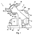
図1は、本発明に係る飲料調製マシン2を含む飲料システム1の側面図を示している。マシン2は、少なくとも加熱器10、ポンプ20、および制御手段30を含むハウジング2aを備える。さらに、マシンは、該マシンと連結されたリザーバ40と、抽出ヘッド50と、支持体(例えば、テーブル)上にマシンを安定的に配置するための足部を備えることが好ましい基部2bとを備える。マシンは、カップなどの受容体Rのためのスタンド2cをさらに備え、スタンド2cは、受容体が配置されるグリッド(grid)2eが備え付けられた上面2dを有する。リザーバ40は、液体供給システムを介して、水などの液体を加熱器10およびポンプ20に供給し、その後、マシン2の抽出ヘッド50に供給する。リザーバ40は、取り外し可能な方法でマシンに連結され、また、液体を導入するための入口40aを有することが好ましい。リザーバ40には、リザーバ40の取扱いを容易にするための取っ手40bが備わっていることが好ましい。これにより、使用者は、好適にリザーバ40を取り扱える。リザーバ40の底に配置されることが好ましい出口(図面には示されていない)によって、リザーバ40とマシン2との接続が行われている。
FIG. 1 shows a side view of a beverage system 1 including a beverage preparation machine 2 according to the present invention. The machine 2 includes a
組み込まれるリザーバ40に加えて、または、代替案として、外部の水供給源(water supply)が用意されてもよいことに留意すべきである。
It should be noted that an external water supply may be provided in addition to or as an alternative to the
マシンの抽出ヘッド50は、該マシンに装着される原材料カプセル54を選択的に格納するための閉鎖機構52と、抽出ヘッド50、その後、カプセル54に、冷水または温水のいずれかを選択的に供給するための制御レバー56とを備える。これに関連して、制御レバー56は、少なくとも、マシン2の制御手段30と接続されている。このようにして、制御レバー56は、ニュートラルな位置から、温水を選択する第1の位置または冷水を選択する第2の位置に切り替えられてもよい。この選択は、マシン2の前後方向において見た場合に、左または右に制御レバー56を動かすことによって、容易に達成されてもよい。したがって、使用者は、冷たい飲料または温かい飲料を調製するために、マシンに装着されたカプセルに冷水または温水のどちらを供給するのかを決定し、その結果、選択することができる。
The
図1から分かるように、原材料カプセル54を保持するための保持手段60を備えるカプセルホルダ58は、抽出ヘッド50の受入チャンバ64(図1には示されていない)内へ受け入れられるように、抽出ヘッド50のアパーチャ62に挿入される。この結果、カプセルホルダは、取り外し可能に、マシンと連結される。受入チャンバ64に接近するためのアパーチャ62は、抽出ヘッドの前面に配置されている。カプセル54を受け入れるための保持手段60は、カプセル54の飲料放出部54a(例えば、出口ポート)が保持手段によって囲まれないように、設計されている。
As can be seen from FIG. 1, a
液体をカプセル54内に導入すると、カプセルの自動的に開く下面が、カプセル54内の圧力上昇により開き、この結果、飲料が、例えば、カプセル54の下方に配置された受容体Rに供給される。さらに、取っ手66が、カプセルホルダ58の好適な取扱いを可能にするために、カプセルホルダ58と連結されている。さらに、カプセルホルダ58には、フロントカバー68が取り付けられており、フロントカバー68は、カプセルホルダ58がアパーチャ62に挿入されるときに、前記アパーチャに蓋をする。
When liquid is introduced into the
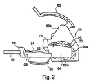
図2に概略的に示されているように、抽出ヘッド50は、注入部材70、および、これらの間に連結された支持体80を備える。なお、これらは双方ともに、抽出ヘッドの内部に配置されている。注入部材70と支持体80との連結は、例えば、参照により本明細書に組み込まれる欧州特許出願公開第2071988号明細書に記載されているような連結機構による周知の方法で行われてもよい。
As schematically shown in FIG. 2, the
閉鎖機構52は、支持体80と受入チャンバ64の後壁64aとの相対運動を可能にしている。支持体80は、下方から、抽出ヘッドのドーム形状部材50aに連結されている。閉鎖機構52が、使用者によって動かされ、下げられると、支持体80が、持ち上げられた開位置または高い開位置(図2に示されている)から、抽出ヘッド50の内部に設けられた案内凹部64bに向けて下げられる。このような案内凹部64bは、受入チャンバ64内に摺動可能に挿置するときにカプセルホルダを案内し、前記カプセルホルダ58を受入チャンバ64内の正しい位置に保持するために設計されている。このようにして、カプセルホルダ58によって保持されたカプセル54は、閉鎖機構52により、受入チャンバ64内に効率的に格納されてもよい。
The
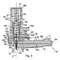
図3は、図2の注入部材70および支持体80の拡大断面図を示している。
FIG. 3 shows an enlarged cross-sectional view of the
図3に示されているように、注入部材70は、穿孔・注入ユニット73を含み、穿孔・注入ユニット73は、出願人の欧州特許第1967100号明細書に記載されているような原材料カプセル54(図2参照)の穿孔または穿刺を行うための穿孔部材または穿刺部材74を有する。部材74は、ステンレス鋼またはセラミック材料から作製された針である。
As shown in FIG. 3, the
穿孔・注入ユニット73は、少なくとも1つの内部貫通チャネル75をさらに有し、内部貫通チャネル75は、穿孔部材の一端74aに対応した入口オリフィス75aから、穿孔機能または穿刺機能を実行するように設計された他端74bに対応した出口オリフィス75bまで延在している。
The piercing / injecting
チャネルは、ポンプ20によって抽出ヘッド50に供給される、水などの液体を、穿孔後の原材料カプセル54内に注入するために使用される。液体は、入口オリフィス75aから導入され、チャネルを通って、カプセル(図3では見ることができない)の内部と連通している出口オリフィス75bまで流れる。
The channel is used to inject a liquid, such as water, supplied by the
上述のような穿孔・注入ユニット73は、図4aおよび図4bにおいて、より詳細に示されており、例えば、針部品の形態をしている。針部品はステンレス鋼から作製されることが好ましい。針部品は、ベースプレート76の上部水平面76aと同一平面になるように取り付けられ、下面76bから突出するように、前記ベースプレートの横断孔内に嵌め込まれている。
The perforation and
注入ユニット73は、必ずしも原材料カプセルを穿孔するわけではなく、カプセルに設けられたアパーチャまたは入口ポート内に嵌め込まれてもよいことに留意すべきである。この点に関して、注入機能だけを実行する注入ユニット73は、他の形態をしていてもよい。あるいは、カプセルは、任意の他の手段によって穿孔されてもよく、この場合も同様に他の形態をとってもよい注入ユニット73は、注入機能だけを実行する。
It should be noted that the
ベースプレート76は、例えば、実質的に円板形状に作られる。ベースプレート76は、例えば、図3に示されている縦断面において、実質的な逆U字形状を有する。逆U字形状は、上面76aと共に内側凹部を形成している外周端76cによって形成されている。
The
支持体80は、内側凹部内に配置された支持プレートを含む。例えば、注入部材は、ゴムベースの材料から作製されてもよく、支持プレート80上に成形されてもよい(例えば、射出成形によって)。図3から分かるように、支持プレート80は、ベースプレート76上に配置されており、図には示されていない方法で図2の抽出ヘッド50と連結されてもよい。
The
また、ベースプレート76は、針部品73が係合されている横断孔の近くの上面76aから縦軸線Zに沿って軸方向に延在している起立部76dを含む。
The
起立部76dの上端からはさらに、実質的にリング形状の延在部76eが、横方向に延在しており、実質的にリング形状の延在部76eは、針部品の横断孔を通過する縦軸線Zの周囲に同心的に、上面76aから任意の距離を置いて配置されている。
Further, a substantially ring-shaped extension 76e extends laterally from the upper end of the
図3から分かるように、リング形状の延在部76eの一端は、起立部76dの上端に固定されており、その他端は、自由である。リング形状の延在部76eは、密封機能を有する。
As can be seen from FIG. 3, one end of the ring-shaped extending portion 76e is fixed to the upper end of the standing
マシンは、注入部材70および針部品の方を向くように配置された洗浄装置90をさらに含む。図示されている実施形態では、洗浄装置90は、針部品の上方に配置されており、また、支持プレート80に接触している中空ケーシング92内に収容されている。より詳細には、ケーシングは、支持プレート80の上面80aに固定されており、一方、支持プレート80の下面80bは、ベースプレート76の上面76aと接触している。
The machine further includes a
ケーシング92の形状は、縦軸線Zに沿って細長くなっており、また、ケーシング92は、針部品の横断孔を通過する前記軸線Zの周囲に同心的に配置されている。 The shape of the casing 92 is elongated along the longitudinal axis Z, and the casing 92 is concentrically disposed around the axis Z passing through the transverse hole of the needle part.
ケーシング92の形状は、実質的に円筒形であるが、他の形態が考えられてもよい。 The shape of the casing 92 is substantially cylindrical, but other forms may be considered.
ケーシング92は、細長い内部キャビティ94を囲んでいる本体92aを有し、本体92aは、そこに洗浄装置90を挿通するために、ケーシングの一方の上端92bにおいて開いている。閉鎖部材97(例えば、キャップ)は、上端ケーシングを一時的に閉鎖するために、取り外し可能に固定されるような仕方で、上端ケーシングに取り付けられる。
The casing 92 has a body 92a that surrounds an elongated internal cavity 94 that is open at one
ケーシングのもう一方の、反対側の下端には、大きな上部開口92bよりも小さな開口92cがある。
There is an
また、ケーシング92は、その本体92aから軸方向および横方向の双方に延在する基部92dを有し、これにより、ショルダが形成されている。
The casing 92 has a
概略的に示されているように、基部ショルダは、上面80aの外縁部から起立し、そこから内側に突出している1つ以上の弾性保持部材96の下に係合されている。この結果、ケーシング92は、上面80aに対して適切な位置にしっかりと保持されている。
As shown schematically, the base shoulder is engaged under one or more resilient retaining
さらに、基部92dには、下方から、中央内側凹部92eが設けられている。
Further, the
この凹部の中心は、開口92cに置かれており、また、この凹部は、開口92cと連通している。
The center of the recess is placed in the
凹部92eの内法寸法は、突出部が、しっかりと凹部に係合されるか、または、スナップ結合され得るように、突出部6eの外法寸法に適合している。 The internal dimension of the recess 92e is adapted to the external dimension of the protrusion 6e so that the protrusion can be securely engaged or snapped into the recess.
突出部76eをケーシング92の凹部92eに挿入する前に、プラグ部材98が、リング形状の突出部76eの中央アパーチャ内に下方からスナップ結合されるか、または、圧力ばめされる。このプラグ部材は、液密機能を実行し、また、その中央部に内部貫通ダクトを有する。内部貫通ダクトは、針部品73の内部貫通チャネル75と位置合わせされている。
Prior to inserting the protrusion 76e into the recess 92e of the casing 92, the plug member 98 is snapped or pressure-fitted into the central aperture of the ring-shaped protrusion 76e from below. The plug member performs a liquid-tight function and has an internal through duct at the center thereof. The internal through duct is aligned with the internal through
支持プレート80をベースプレート76の凹部内に配置する前に、案内部材99が、支持プレート80をその厚さ全体にわたって横断している孔に挿入される。
Prior to placing the
案内部材99は、中央貫通ダクトを有し、この中央貫通ダクトは、支持プレート80がベースプレートの凹部内に収容されるときに、針部品73の内部貫通チャネル75、および、プラグ部材98の内部貫通ダクトと位置合わせされる。案内部材99の形状は、例えば、実質的に円筒形である。
The guide member 99 has a central through duct, which, when the
また、ケーシング92には、内部キャビティ94への液体の圧力下での導入を可能にする少なくとも1つの入口開口が設けられている。図3に示されている実施形態では、ケーシング92には、2つの別個の入口開口92fおよび92gが設けられており、入口開口92fおよび92gは、それぞれ、本体92aを構成している壁から外に向かって突出したダクトの形態をしている。ダクト92fおよび92gは、壁を貫通して内部キャビティ94内に出ている。
The casing 92 is also provided with at least one inlet opening that allows introduction of liquid into the internal cavity 94 under pressure. In the embodiment shown in FIG. 3, the casing 92 is provided with two
図3に描かれているように、双方のダクトは、アセンブリ(ケーシング92を伴う、注入部材70および支持プレート80)のサイズ全体が大きくならないように、支持プレート80の中央部の上方の、ケーシングの同じ側面に配置されている。
As depicted in FIG. 3, both ducts have a casing above the center of the
さらに、ダクトの一方は、他方の上方に配置されている。ダクトの一方が、温かい液体(例えば、水)のために使用される一方で、他方は、周囲温度にある液体(例えば、水)のために使用される。これらのダクトは、液体供給システムを介して、ポンプ70と連通している。
Furthermore, one of the ducts is disposed above the other. One of the ducts is used for a warm liquid (eg water) while the other is used for a liquid (eg water) at ambient temperature. These ducts communicate with the
洗浄装置90は、図4aおよび図4bに概略的に示されているような2つの主要位置の間を縦軸線Zに沿って移動可能である支持部材100を含む。より詳細には、支持部材は、細長い内部キャビティ94内を摺動可能である。また、洗浄装置90は、支持部材100と連結され、したがって、支持部材100と共に動く細長い洗浄部材102を含む。
The
細長い洗浄部材102は、一端において、取り外し可能に支持部材と連結されてもよいし、または、恒久的に支持部材に固定されてもよく、他端は、自由である。 The elongate cleaning member 102 may be removably coupled to the support member at one end or may be permanently fixed to the support member, the other end being free.
細長い洗浄部材102の形態は、例えば、ピンであってもよい。 The shape of the elongated cleaning member 102 may be a pin, for example.
細長い洗浄部材102は、内部チャネル75の形状および内部寸法(例えば、内径)にそれぞれ適合する形状および外法寸法を有する。
The elongate cleaning member 102 has a shape and outer dimensions that match the shape and inner dimensions (eg, inner diameter) of the
このようにして、洗浄部材102は、洗浄目的でマシンを使用する過程において、チャネル75内の前後運動に従うことができる。
In this way, the cleaning member 102 can follow a back-and-forth movement in the
洗浄部材102の形状および外法寸法はまた、洗浄部材102の摺動が円滑になるように、それぞれ、プラグ部材98ならびに案内部材99の形状および内部寸法に適合していることに留意すべきである。 It should be noted that the shape and external dimensions of the cleaning member 102 are also adapted to the shapes and internal dimensions of the plug member 98 and guide member 99, respectively, so that the sliding of the cleaning member 102 is smooth. is there.
具体的には、案内部材99は、洗浄部材102がチャネル75内を摺動する間、洗浄部材102を縦方向に案内する。
Specifically, the guide member 99 guides the cleaning member 102 in the vertical direction while the cleaning member 102 slides in the
支持部材100は、実質的に円筒形の外形を有し、その寸法は、摺動目的のために内部キャビティ94の寸法にぴったりと適合している。
The
支持部材100は、本体部100aを含み、本体部100aは、支持部品または基部100bから軸方向に延在しており、支持部品または基部100bは、軸方向の延在部に対して横方向にあり、支持部材の閉鎖端(下端)を形成している。
The
図3の実施形態では、軸方向の延在部は、垂直な縦軸線Zに沿うものである。しかしながら、図3のアセンブリ(注入部材70および洗浄装置90)の他の幾何学的配置も考えられ得る。例えば、縦軸線Zは、水平であってもよいし、または、水平方向と垂直方向との間に傾斜していてもよい。
In the embodiment of FIG. 3, the axial extension is along the vertical longitudinal axis Z. However, other geometric arrangements of the assembly of FIG. 3 (
細長い洗浄部材102は、支持部品100bに固定された端部を有する。この端部は、支持横部品100bに形成された孔に圧力ばめされてもよい。
The elongated cleaning member 102 has an end fixed to the
本体部100aは、支持部材の反対側の開放端(上端)に至るまで軸方向に延在し続けながら、支持横部品100bからある距離だけ半径方向または横方向に延在している。
The
半径方向または横方向への延在によって、ショルダ100c(これは横部品である)が形成されており、この結果、ショルダ100cによって、本体壁92aの内面と、ショルダの下方に位置する、本体部100aの部分との間に空間104が空けられている。本体部100aのこの部分の横断寸法は、ショルダ100cよりも狭くなっている。
The
この例では、空間104は、環状円筒部の形態をしている。
In this example, the
図3に示されているように、支持部材の最も低い位置では、ショルダ100c(横部品)が、最も高い延出ダクト(emerging highest duct)92gの上方に配置されている。
As shown in FIG. 3, at the lowest position of the support member, a
この配置は、液体が導入される貫通入口ダクト92gが、支持部材がどこの位置にあっても、空間104と常に連通することを確実にするためになされている。
This arrangement is made to ensure that the through-
支持部材の細長い本体部100aは、中空であり、内部ハウジング100dを有する。
The
内部ハウジング100dの一端(下端)は、支持横部品100bの内面100eによって境界付けられており、また、内部ハウジング100dの他端(上端)は、内部キャビティ94と連通するように開いている。
One end (lower end) of the
ハウジング100dは、例えば、円筒形状に作られる。
The
洗浄装置90は、第1の所定の力F1を支持部材100に対して恒久的に加える能動的手段をさらに含む。
The
この力F1は、縦軸線Zに沿った方向に加えられ、ここでは、図3、図4a、および図4bに示されているように下方向に向けられている。 This force F1 is applied in a direction along the longitudinal axis Z, where it is directed downward as shown in FIGS. 3, 4a and 4b.
能動的手段は、図面のばね手段106などの弾性手段であることが好ましい。しかしながら、同じ役割を演じる他の能動的手段が、代わりに使用されてもよい。例えば、圧力下で流体をハウジング100d内に注入するのに適した空気圧手段または注入手段が、考えられてもよい。
The active means is preferably an elastic means such as the spring means 106 in the drawing. However, other active means that play the same role may be used instead. For example, pneumatic means or injection means suitable for injecting fluid into the
このような流体は、リザーバ40から取り出される水であってもよい。
Such fluid may be water that is removed from the
図3の実施形態では、ばね手段106は、一端が内面100eに固定され、他端が閉鎖部材97の内面に固定されている。
In the embodiment of FIG. 3, the spring means 106 has one end fixed to the inner surface 100 e and the other end fixed to the inner surface of the closing
図3に示されている位置において、内面100eに加えられる第1の恒久的な力F1は、注入液体(例えば、水)がない場合、任意の反対方向の力によって相殺されない。 In the position shown in FIG. 3, the first permanent force F1 applied to the inner surface 100e is not offset by any opposite force in the absence of the injected liquid (eg, water).
このように、支持部材100は、その最も低い位置をとるように付勢されており(図4bも参照)、したがって、細長い洗浄部材102は、洗浄目的のためにチャネル75に挿入されるように付勢されている(第1の作動位置)。
Thus, the
洗浄部材102の長さは、図3 および図4bにおける出口オリフィス75bに届き得るように適切な長さになっていなければならないことに留意すべきである。
It should be noted that the length of the cleaning member 102 must be of an appropriate length so that it can reach the
しかしながら、使用者が、原材料カプセルをマシンに挿置した後に、飲料調製マシンを作動させるとき、抽出ヘッド50の閉鎖機構52は、支持体80および注入部材70を備えるアセンブリを下げて、マシンを閉じるために、閉位置まで動かされなければならない。次に、使用者は、始動ボタンもしくは始動部材を押すことによって、および/または、制御レバー56を操作することによって、および/または、任意の他の始動手段または起動手段によって、マシンを始動させる。次に、液体(例えば、水)が、液体供給源またはリザーバ40からの液体を圧送するポンプ20によって、マシンの液体供給システム内に供給され始める。これにより、液体は、使用者の選択(温かい飲料または周囲温度の飲料)に応じて、2つのダクト92fおよび92gの一方に運ばれる。
However, when the user operates the beverage preparation machine after inserting the raw material capsule into the machine, the
次に、圧力下の液体は、空間104(図3)内に導入され、これを満たす。 Next, the liquid under pressure is introduced into and fills the space 104 (FIG. 3).
空間104がこのように満たされ、液体が入口ダクトから流れ続けると、空間内の液体の圧力が、増大し、特に、ショルダ100cによって形成された横部品に作用し、この結果、支持部材100を持ち上げる。
As the
液体圧力は、第1の所定の力F1を相殺し、支持部材100を押し上げるのに十分な高さがある。
The liquid pressure is high enough to offset the first predetermined force F1 and push up the
内面100eの反対側にある、支持横部品100bの外面100gが、出口開口92cから離れると、圧力液体は、さらに外面100gに対して作用して、支持部材100をその静止位置(図4a)に向かって動かすことに寄与する。
When the
図4aに示されているように、液体圧力は、外面100gおよびショルダ100cの双方に作用し、また、反対方向の力F2(縦方向に向けられた)によって概略的に示されている。力F2は、力F1よりも大きい。
As shown in FIG. 4a, the liquid pressure acts on both the
支持部材100の縦方向の運動の過程で、細長い洗浄部材102は、内部貫通チャネル75から次第に引き抜かれる。この引抜きは、洗浄部材102が、チャネル75の内面を磨くことを可能にする。
In the course of the longitudinal movement of the
洗浄部材102が、チャネル75および出口開口92cから完全に取り除かれると、液体(例えば、水)が、出口開口92cならびに部材98および99の連続したダクトに導入され、その後、チャネル75に到達し、次に、図面には示されていない原材料カプセルに注入される。
When the cleaning member 102 is completely removed from the
図4aに示されているように、静止位置では、洗浄部材102は、より大きな力F2によりばね手段106を圧縮する液体圧力によってチャネル75の外にある状態で保持される。
As shown in FIG. 4a, in the rest position, the cleaning member 102 is held out of the
液体注入が停止されると(マシンの動作の終了)、液体圧力は、急速に低下し、この結果、第1の所定の力F1が、液体圧力による力を上回ることが可能になる。次に、支持部材100が、力F1の作用下で下方に向かって動かされ(図4b)、洗浄部材102が、チャネル75に押し入れられ、出口オリフィス75bまで通される。
When the liquid injection is stopped (end of machine operation), the liquid pressure drops rapidly, so that the first predetermined force F1 can exceed the force due to the liquid pressure. Next, the
チャネル75内の摺動中に、洗浄部材102は、チャネル75の内面と接触するようになり、この結果、チャネルの内部に蓄積している可能性のある任意の可能な付着物、残骸(例えば、スケール付着物)を除去することができる。
During sliding within the
図4bに示されている位置において、洗浄部材102は、出口オリフィス75bに到達しており、マシンの次の作動までチャネル内部にとどまる。これにより、マシンが静止しているときに洗浄部材があるため、付着物がチャネル内に形成され得ないという点で、付加的な利点がもたらされる。
In the position shown in FIG. 4b, the cleaning member 102 has reached the
図4aおよび図4bでは、支持体80は、明確にするために点線によって概略的に描かれている。
In FIGS. 4a and 4b, the
さらなる適切な封止手段(図面には示されていない)が、図3に示されているアセンブリの様々な部品間の、液体の任意の漏れを防止するために、使用されてもよい。 Further suitable sealing means (not shown in the drawing) may be used to prevent any leakage of liquid between the various parts of the assembly shown in FIG.
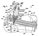
次に、飲料調製マシン200およびこれに関連するシステムの別の実施形態について、図5〜図7を参照しながら説明する。
Next, another embodiment of the
図1および図2に関してなされた上記説明が、依然として適用可能であり、ここでは繰り返されない。 The above description made with respect to FIGS. 1 and 2 is still applicable and will not be repeated here.
図1および図2に関係する参照符号は、修正された注入部材70および洗浄装置90を除いて、ここに引き継がれる同じ部品のために残されている。
Reference numerals relating to FIGS. 1 and 2 remain for the same parts carried over here, except for the modified
図5は、高い開位置にある場合の、図2の抽出ヘッド50の内部の拡大部分断面図を示している。この位置では、飲料調製マシンは、アパーチャ62(図2)を介して原材料カプセルが導入されることを可能にするために開いている。図7は、マシンの閉位置を示している。
FIG. 5 shows an enlarged partial cross-sectional view of the interior of the
図5に示されているように、修正された注入部材202は、注入部材70および支持体80に関して上述されているのと同じ方法で、支持体80と連結されている。
As shown in FIG. 5, the modified
注入部材は、組み立てられた注入ベースプレート206および支持プレート80の厚さ全体にわたって延在する穿孔・注入ユニット204を含む。
The injection member includes a drilling and
穿孔・注入ユニット204は、図2のカプセル54などの原材料カプセルを穿孔するための穿孔部材208を有する。
The piercing / injecting
穿孔部材208の機能は、カプセルの壁に孔もしくはアパーチャ(または複数の孔もしくはアパーチャ)を、この孔によって前記カプセルへの液体の注入が可能になるように、形成することである。この孔もしくはアパーチャ(またはこれらの孔)は、穿刺手段または引裂き手段などの任意の他の手段によって形成されてもよい(これらの注釈は、図1〜図4bを参照しながら説明した実施形態にも当てはまる)。
The function of the piercing
また、ユニット204は、交互に、必ずしも、孔またはアパーチャを原材料カプセルに形成するために使用されなくてもよく、前記カプセルに予め設けられた孔またはアパーチャまたは入口ポートに通されてもよい。
Alternately, the
これらの環境下では、注入機能のみを実行する注入ユニット204は、他の形態(導管、パイプ、ノズルなど)をしていてもよい。
Under these circumstances, the
あるいは、カプセルの穿孔、穿刺、引裂きなどは、任意の他の異なる手段によって行われてもよく、この場合も同様に他の形態をとってもよい注入ユニット204は、注入機能だけを実行する。
Alternatively, capsule piercing, puncturing, tearing, etc. may be performed by any other different means, and the
また、穿孔・注入ユニット204は、ポンプ20によって抽出ヘッド50に供給される液体を、穿孔後の原材料カプセルに注入するために使用される少なくとも1つの内部貫通チャネル210を有する。
The perforation /
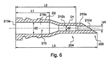
図6は、ここでは例えば針部品の形態をしているユニット204の詳細な断面図を示している。
FIG. 6 shows a detailed cross-sectional view of the
図示されているように、ユニット204(針部品)は、3つのチャネル部210a〜210cを備え、これらは、チャネル210を、
チャネル210の自由延出端210dを含む第1のチャネル部210aであって、自由延出端210dを介して、液体が、前記チャネルを出て、原材料カプセルに入り(液体は、第1のチャネル部210aの小さな直径d1により、噴流の形態で自由端210d(出口オリフィス)から噴出される)、第1のチャネル部の長さが、特に目詰まりのリスクを低減するために、可能な限り小さくなければならない第1のチャネル部210aと、
第2の中間チャネル部210bであって、第1のチャネル部210aの上流に配置され、拡大された第2の内径d2を有し、第2のチャネル部210bの長さが、第1のチャネル部210aよりも大きく、ユニット204の外径D1が、第1のおよびチャネル部210aおよび210bにわたって同じままである第2のチャネル部210bと、
第3のチャネル部210cであって、第2のチャネル部210bの上流に配置され、入口オリフィスが配置された、チャネルの他端210cを含み、この入口オリフィスを介して、液体が、チャネルに侵入し、この第3の部が、拡大された第3の内径d3、拡大された外径D2、および、第2のチャネル部よりも大きな長さを有する第3のチャネル部210cと
に分割している。
As shown, the unit 204 (needle component) comprises three
A
A second
A
ユニット204の自由延出端の近くの、ユニット204の外径D1は、十分に小さく、この外径がその全長にわたって保たれている、この部材の長さは、穿孔または穿刺などによって原材料カプセルの壁に孔またはアパーチャを効率的に形成するために十分に長くなっている。第2の中間チャネル部がなく、第3のチャネル部だけがある場合、穿孔部材の外径は、第1のチャネル部の上流端においてD2と等しくなる。これによって、穿孔部材は低効率なものとなる。しかしながら、第2の中間チャネル部は、除去されてもよい。この場合、D1の外径を有する穿孔部材と同じ長さを保つために、D2と等しい外径を有する穿孔部材の部分が、より長くされるか、または、交互に、第1のチャネル部210aの長さが、より長くされる。
The outer diameter D1 of the
例として、内径d1、d2、およびd3が、それぞれ、0.6、0.8、および1.8mmと等しく、D1が1.5mmと等しく、D2が2.6と等しく、第3のチャネル部210cの長さL1が5mmと等しく、長さL2およびL3が、それぞれ、8.9および12mmであってもよい。針部品204はステンレス鋼から作製されるのが好ましい。
As an example, the inner diameters d1, d2, and d3 are respectively equal to 0.6, 0.8, and 1.8 mm, D1 is equal to 1.5 mm, D2 is equal to 2.6, and the third channel portion The length L1 of 210c may be equal to 5 mm, and the lengths L2 and L3 may be 8.9 and 12 mm, respectively.
図6に示されているように、拡大された外径D2を有する、穿孔部材の部分は、図5および図7の支持プレート80に設けられた貫通孔に挿入するのに十分な程度には硬くなっている。穿孔部材の外面に配置された突出部品は、保持部品として機能する。
As shown in FIG. 6, the portion of the piercing member having an enlarged outer diameter D2 is sufficient to be inserted into the through hole provided in the
図6に示されている穿孔・注入ユニット204は、任意の他の種類の飲料調製マシンにおいて使用されてもよく、この場合、孔またはアパーチャが、原材料カプセルに(例えば、その壁に)形成されなければならず、また、液体は、この孔またはアパーチャを介して注入されなければならないことに留意すべきである。図1および図2に示されているマシンは、特に、取り外し可能な連結またはこれ以外によってそのような穿孔・注入ユニットを含むのに適している。
The piercing and
しかしながら、異なる機構および幾何学的形状を有する任意の他のタイプのマシンが、好適であってもよい。 However, any other type of machine with different mechanisms and geometric shapes may be suitable.
図5に戻ると、組み込まれたユニット(または針部品)204は、支持プレート80の上面80aと同一平面になるよう取り付けられ、注入部材202の下面202aから突出するように、配置されている。
Returning to FIG. 5, the assembled unit (or needle part) 204 is attached so as to be flush with the
マシン200は、注入部材202およびユニット204の方を向いていて、これらの上方に配置された洗浄装置220をさらに備える。
The
図示されているように、洗浄装置220は、中空ケーシング222内に収容されており、中空ケーシング222は、維持手段によって支持プレート80の上面80aに接触した状態で維持されている。例えば、ケーシング222の外面に形成されたショルダ222aおよび222bは、ケーシング222を適切な位置に維持するために、抽出ヘッド50の構造手段と協働する。
As illustrated, the
ケーシング222の形状は、縦軸線に沿って細長くなっており、また、ケーシング222は、針部品の横断孔を通過する前記軸線の周囲に同心的に配置されている。
The shape of the
ケーシング222の形状は、実質的に円筒形であるが、他の形態が考えられてもよい。
The shape of the
ケーシング222は、細長い内部キャビティ224を囲んでいる本体222aを有し、本体は、洗浄装置220を挿通するために、ケーシングの一方の上端222bにおいて開いている。
The
ケーシング222は、その下端に基部222cを有する。中央貫通孔222d(図7)が、ケーシングの延在部と内部キャビティ224との連通を可能にするために、基部に形成されている。環状凹部222eが、下方から基部222cに設けられており、孔222dを囲んでいる。環状凹部22e(例えば、環状円筒部の形状の)は、密封機能を有する図3の突出部76e(リング形状部)を収容している。貫通孔222dは、針部品204の内部貫通チャネル210と位置合わせされている。
The
また、ケーシング222には、内部キャビティ224への液体の圧力下での導入を可能にする少なくとも1つの入口開口が設けられている。図5および図7に示されている実施形態では、ケーシング222には、2つの別個の入口開口222fおよび222gが設けられており、入口開口222fおよび222gは、それぞれ、本体222aを構成している壁から外に向かって突出したダクトの形態をしている。ダクト222fおよび222gは、壁を貫通して内部キャビティ224内に出ている。
The
図5および図7に描かれているように、双方のダクトは、アセンブリ(洗浄装置を格納している注入部材202およびケーシング222)のサイズ全体が大きくならないように、支持プレート80の中央部の上方の、ケーシングの同じ側面に配置されている。
As depicted in FIGS. 5 and 7, both ducts are located in the central portion of the
さらに、ダクトの一方は、他方の上方に配置されている。ダクトの一方が、温かい液体(例えば、水)のために使用される一方で、他方は、周囲温度にある液体(例えば、水)のために使用される。これらのダクトは、例えば可撓性パイプを含む液体供給システムを介してポンプ20(図1)と連通している。 Furthermore, one of the ducts is disposed above the other. One of the ducts is used for a warm liquid (eg water) while the other is used for a liquid (eg water) at ambient temperature. These ducts communicate with pump 20 (FIG. 1) via a liquid supply system including, for example, a flexible pipe.
洗浄装置220は、図5および図7に概略的に示されているような2つの主要位置の間をケーシング222の縦軸線に沿って移動可能である支持部材226を含む。より詳細には、支持部材226は、案内部材228を介して細長い内部キャビティ224内を摺動可能である。案内部材228は、例えば、リング形状を有し、縦方向に形作られた支持部材226の周囲に取り付けるための中央孔を有する。案内部材228には、液体の通過を可能にする横断孔が設けられている。さらに、案内部材は、支持部材226の周囲の、支持部材が縮小された部分によりショルダを有する領域に適合されている。案内部材228の外径は、摺動目的のために内部キャビティの寸法に適合している。
The
支持部材226は、ケーシング222の上端から突出している。閉鎖部材230は、ケーシング222の開いた上端を閉鎖しており、また、閉鎖部材230には、支持部材226を受け入れ、支持部材226の摺動を可能にするための中央内部孔が設けられている。閉鎖部材は、例えば、支持部材226と接触する内周封止具(例えば、Oリング、クワッドリング(Quad−ring)、ダブルデルタシール(Double Delta seal)など)を伴うフランジである。閉鎖部材は、取り外し可能に固定される周知の方法で、ケーシングに取り付けられている。
The support member 226 protrudes from the upper end of the
また、洗浄装置220は、支持部材226と連結されており、したがって、支持部材226と共に動く細長い洗浄部材232を含む。
The
細長い洗浄部材232は、一端において、支持部材の端部と取り外し可能に連結されてもよいし、または、これに恒久的に固定されてもよく、細長い洗浄部材の他端は、自由である。例えば、部材232は、一部が縮小された、支持部材226の端部と連結される。この縮小された部分は、貫通孔222dの寸法に適合している(図7)。
The
支持部材226と細長い洗浄部材232とは、一直線になっている。
The support member 226 and the
細長い洗浄部材232の形態は、例えば、ピンであってもよい。
The form of the
細長い洗浄部材232の形状および外法寸法(例えば0.5mmの外径)は、それぞれ、内部貫通チャネル210、詳細には、その最も小さなチャネル部の形状および内部寸法(例えば、内径)に適合している。
The shape and outer dimensions (e.g., 0.5 mm outer diameter) of the
このようにして、洗浄部材232は、洗浄目的でマシンを使用する過程において、チャネル210、詳細には、第1のチャネル部210a内の前後運動に従うことができる。
In this manner, the cleaning
図5および図7に示されているように、支持部材226は、両側の2つの端部を有し、一方の端部226aは、細長い洗浄部材232と連結され、一方、他方の反対側の端部226bは、リンク機構を介してマシンの固定部品と連結されている。
As shown in FIGS. 5 and 7, the support member 226 has two ends on both sides, one
詳細には、反対側の端部226bは、シャフト234(またはピン部材)と連結されており、シャフト234は、レール部材またはスロットなどの案内手段236内を平行移動するよう自由に取り付けられている。案内手段は、閉じられているか、または、シャフト234が移動する経路の端を形成するその両側の2つの端部に、2つの停止具を備える。
Specifically, the
図示されているように、案内部材236は、注入ユニットの実質的に円を成す(円周の一部に沿う)下向きの運動に従うよう構成されるように、水平線および垂直線に対して傾斜している。
As shown, the
例えば、反対側の端部236bは、支持部材226に対して垂直に配置され、かつ案内部材236と摺動可能に係合しているシャフト234を中心に回転するよう、自由に回転可能に取り付けられる。
For example, the opposite end 236b is freely rotatably mounted to rotate about a
案内手段236は、飲料調製マシンの筐体と固定連結されたキャリア238に設けられている。例えば、キャリア238は、図面の断面に示されている水平部分、および、隠れている筐体に固定された2つの下向きの垂直アームを有する、逆U字の形態をとってもよい。案内手段236は、例えば、キャリア238の水平部分と一体的に作製される。
The guide means 236 is provided on a
図5(開位置にあるマシン)に示されているように、注入ユニットおよび洗浄装置を備えるアセンブリを含む抽出ヘッド50は、マシン内への原材料カプセルの導入を待つ高い位置にある。この位置において、支持部材226は、より低い位置にあり(案内部材228は、内部キャビティ224の底に当接している)、細長い洗浄部材は、その先端232aがチャネルの自由延出端210dを貫通するように、チャネル210内に完全に挿入されている(細長い洗浄部材の第1の作動位置)。一方、シャフト234は、案内手段236の一端(その上部にある)に配置されており、案内手段の停止端に接触している。
As shown in FIG. 5 (machine in open position), the
原材料カプセルが、使用者によってマシンに導入されるとき、マシンは閉じられ得る(図1の位置)。より詳細には、マシンの閉鎖は、図2(および図5)に示されている位置から、図1(および図7)の位置まで閉鎖機構52を動かすことによって実現される。
When the raw material capsule is introduced into the machine by the user, the machine can be closed (position in FIG. 1). More specifically, the closing of the machine is achieved by moving the
図5の位置から図7の位置までマシンを動かす過程で、シャフト234は、案内部材236(例えば、レール部材またはスロット)の反対側の停止端まで下に向かって摺動する。
In the process of moving the machine from the position of FIG. 5 to the position of FIG. 7, the
この配置は、支持部材226を保持するための保持手段として機能し、一方、注入ユニット(より詳細には、注入部材202、支持体80、およびケーシング222)は、図7の閉位置に到達するために下方へ動き続ける。
This arrangement functions as a holding means for holding the support member 226, while the injection unit (more specifically, the
このようにして、支持部材226は、さらに下方へ動くことを制限されるため、支持部材226と連結されている細長い洗浄部材232もまた、上の位置に保持され、したがって、チャネル210から部分的に引き抜かれる。
In this way, since the support member 226 is restricted from moving further downwards, the
図7に示されているように、部材232は、その自由な先端が第3のチャネル部(第2の静止位置)に配置されるように、第1のチャネル部210aおよび第2のチャネル部210bから引き抜かれる。これにより、この位置では、液体が、噴流の形態で出口オリフィス210aを介して出て行く前に、ダクト222fおよび222gの一方、内部キャビティ224、貫通孔222d、ならびに内部チャネル部210c、210b、および210aを介して、連続的に導入されることが可能になる。噴流は、原材料カプセル内に注入される。
As shown in FIG. 7, the
図6に示されている注入ユニットの内部構造のおかげで、内部貫通チャネル210から細長い洗浄部材232の一部だけを引き抜くことが可能になっている。
Thanks to the internal structure of the injection unit shown in FIG. 6, only a portion of the
したがって、このことは、部材232および支持部材226が移動する経路の長さが、チャネルから部材232を完全に取り除くために必要なものと比べて短いため、好適である。
This is therefore preferred because the length of the path along which
したがって、案内手段236内のシャフト234が移動する経路に対応するこの短い経路は、マシンの外寸を修正することなく、マシン内に容易に収めることができる。
Therefore, this short path corresponding to the path along which the
図5の位置から図7の位置まで、および、これとは逆にマシンを動かすとき、細長い洗浄部材232は、チャネル210内、詳細には、スケール付着物などの残骸、付着物による目詰まりを最も起こしやすい第1のチャネル部210a内を摺動する。
When moving the machine from the position of FIG. 5 to the position of FIG. 7 and vice versa, the
摺動は、チャネル部を形成している壁の内面に蓄積する可能性のある任意の付着物の除去を可能にする。 Sliding allows the removal of any deposits that may accumulate on the inner surface of the wall forming the channel portion.
マシンを、図7の位置から図5の位置まで開くために動かすとき、支持部材および細長い洗浄部材は、注入ユニットに対して、逆方向に移動する。次に、細長い洗浄部材は、液体が第2のチャネル部および第1のチャネル部を流れた後の、これらの洗浄のために、第2のチャネル部および第1のチャネル部に導入される。この洗浄装置およびこれに関連する機構は、特に信頼性が高いことに留意すべきである。さらに、洗浄は、マシンが、カプセルの導入およびカプセルの取外しのために2回開かれることから、マシンの使用サイクルごとに2回行われる。 As the machine is moved to open from the position of FIG. 7 to the position of FIG. 5, the support member and the elongated cleaning member move in the opposite direction relative to the injection unit. The elongate cleaning member is then introduced into the second channel portion and the first channel portion for cleaning after the liquid has flowed through the second channel portion and the first channel portion. It should be noted that this cleaning device and the mechanisms associated therewith are particularly reliable. In addition, cleaning is performed twice for each use cycle of the machine because the machine is opened twice for capsule introduction and capsule removal.
原材料カプセル54は、飲料、もしくは、ほとんどの場合、液体食品を調製するために液体(例えば、水)を加えることによって使用される食品原材料または食品物質を含むことに留意すべきである。
It should be noted that the
このような原材料は、コーヒー、例えば、焙煎して挽いたコーヒーであってもよい。 Such raw materials may be coffee, for example roast and ground coffee.
他の原材料は、非限定的に、例えば、茶(葉茶、ハーブティー、もしくはフルーツティー)、可溶性の茶もしくは可溶性のコーヒー、挽いたコーヒーおよび可溶性のコーヒーの混合物、ココア、もしくはココア、またはホットチョコレートベースの製品、またはコーヒー、スープ、もしくは浸出の形態のものなどの食品を含む補助製品を含む。 Other raw materials include, but are not limited to, tea (leaf tea, herbal tea, or fruit tea), soluble tea or soluble coffee, a mixture of ground and soluble coffee, cocoa, or cocoa, or hot Includes supplement products including chocolate-based products or foods such as those in the form of coffee, soup, or brew.
任意の原材料カプセル(例えば、フィルターポッドなどのオープンカプセル)が、使用されてもよいことに留意すべきである。 It should be noted that any raw material capsule (eg, an open capsule such as a filter pod) may be used.
変形例として、ダクトなどの手段によって連結され得る1つよりも多い針部品を有する注入部材を設計することが可能である。 As a variant, it is possible to design an injection member having more than one needle part that can be connected by means such as a duct.
これらの針部品のパターンおよび設計は、調製される飲料の注入条件に関する様々な要求を満たすために変更されてもよい。具体的には、注入条件は、特に、原材料カプセル54内に用意された物質の溶解および/または抽出に関して、変更されてもよい。
The pattern and design of these needle parts may be modified to meet various requirements regarding the infusion conditions of the beverage to be prepared. In particular, the injection conditions may be varied, particularly with respect to the dissolution and / or extraction of the substance provided in the
本明細書に記載されている現時点で好ましい実施形態に対する様々な変更および修正は、当業者には明らかであることが理解されるべきである。このような変更および修正は、本発明の精神および範囲から逸脱することなく、また、その付随的な利点を損なうことなく、行うことができる。したがって、上記の変更および修正は添付の特許請求の範囲によって含まれることが意図されている。 It should be understood that various changes and modifications to the presently preferred embodiments described herein will be apparent to those skilled in the art. Such changes and modifications can be made without departing from the spirit and scope of the present invention and without diminishing its attendant advantages. Accordingly, such changes and modifications are intended to be encompassed by the appended claims.
Claims (18)
原材料カプセル(54)および飲料調製マシン(2、200)を備え、
該飲料調製マシン(2、200)が、
前記液体を前記原材料カプセルに注入するための少なくとも1つの内部貫通チャネル(75、210)を有する注入ユニット(73、204)と、
前記飲料調製マシンに前記飲料を調製させるための作動手段と
を有する飲料調製システム(1)において、
前記飲料調製マシンが、前記少なくとも1つの内部貫通チャネルを自動的に洗浄するための洗浄装置(90、220)をさらに備え、前記洗浄装置が、前記作動手段によって駆動されることを特徴とする、飲料調製システム(1)。 A beverage preparation system (1) for preparing a beverage by injecting liquid into a raw material capsule,
Comprising a raw material capsule (54) and a beverage preparation machine (2,200),
The beverage preparation machine (2,200)
An injection unit (73, 204) having at least one internal through channel (75, 210) for injecting the liquid into the raw material capsule;
In a beverage preparation system (1) having operating means for causing the beverage preparation machine to prepare the beverage,
The beverage preparation machine further comprises a cleaning device (90, 220) for automatically cleaning the at least one internal penetration channel, the cleaning device being driven by the actuating means, Beverage preparation system (1).
液体供給源(10)と、
前記液体供給源から前記注入ユニット(73)に向けて前記液体を圧送するためのポンプ(20)と、
前記供給源から前記注入ユニットに向けて前記液体を圧送させるための始動手段と
を有し、前記洗浄装置(90)が、前記始動手段によって駆動されることを特徴とする、請求項1〜10のいずれか一項に記載の飲料調製システム。 The beverage preparation machine (2)
A liquid source (10);
A pump (20) for pumping the liquid from the liquid source toward the injection unit (73);
11. A starting means for pumping the liquid from the supply source towards the injection unit, the cleaning device (90) being driven by the starting means. The beverage preparation system according to any one of the above.
前記洗浄装置が、
支持部材(100、226)と、
前記チャネルを洗浄するために該チャネルに挿入されるのに適した、前記支持部材と連結された細長い洗浄部材(102、232)と
を含み、
前記支持部材および前記細長い洗浄部材が、第1の作動位置をとるために付勢されるようにして、所定の力の作用によって前方に移動可能であり、前記第1の作動位置では、前記細長い洗浄部材が、前記チャネル(75、210)内を、該チャネル(75、210)の自由延出端まで貫通し、前記支持部材および前記細長い洗浄部材が、第2の静止位置をとるために付勢されるようにして、反対方向の所定の力の作用によって後方に移動可能であり、前記第2の静止位置では、前記細長い洗浄部材が、前記チャネルから少なくとも部分的に引き抜かれる、アセンブリ。 An assembly comprising a channel (75, 210) through which a liquid flows temporarily and a cleaning device for cleaning the channel,
The cleaning device is
A support member (100, 226);
An elongate cleaning member (102, 232) coupled to the support member suitable for being inserted into the channel for cleaning the channel;
The support member and the elongate cleaning member can be moved forward by the action of a predetermined force such that the support member and the elongate cleaning member are biased to assume a first operating position, and in the first operating position, the elongate cleaning member is movable. A cleaning member passes through the channel (75, 210) to the free extending end of the channel (75, 210), and the support member and the elongated cleaning member are attached to assume a second rest position. An assembly that is biased so that it can be moved backwards by the action of a predetermined force in the opposite direction, and in the second rest position, the elongate cleaning member is at least partially withdrawn from the channel.
前記飲料調製マシンが、前記液体を前記原材料カプセルに注入するための少なくとも1つの内部貫通チャネル(75、210)を有する注入ユニット(73、204)を備え、
原材料カプセル(54)を準備するステップと、
前記飲料調製マシンに前記飲料を調製させるために前記飲料調製マシンを作動させる作動ステップと
を含む方法において、
前記少なくとも1つの内部貫通チャネルを洗浄する洗浄ステップをさらに備え、
該洗浄ステップが、前記飲料調製マシンを作動させるための前記作動ステップが実行されたときに、自動的に開始されることを特徴とする、方法。 A method for preparing a beverage using a beverage preparation machine (2,200) by injecting a liquid into a raw material capsule, comprising:
The beverage preparation machine comprises an injection unit (73, 204) having at least one internal through channel (75, 210) for injecting the liquid into the raw material capsule;
Providing a raw material capsule (54);
Actuating the beverage preparation machine to cause the beverage preparation machine to prepare the beverage;
A cleaning step of cleaning the at least one internal through-channel,
Method according to claim 1, characterized in that the washing step is started automatically when the operating step for operating the beverage preparation machine is performed.
前記少なくとも1つの内部貫通チャネルを介して前記液体を前記原材料カプセルに注入するステップをさらに含み、
前記自動的な洗浄ステップが、前記液体の注入の前に、および/または、間に、および/または、後に実行されることを特徴とする、請求項16または17に記載の方法。 The beverage preparation machine comprises a liquid source (10) and a pump (20);
Injecting the liquid into the raw material capsule via the at least one internal through-channel,
18. A method according to claim 16 or 17, characterized in that the automatic washing step is carried out before and / or during and / or after the injection of the liquid.
Applications Claiming Priority (3)
| Application Number | Priority Date | Filing Date | Title |
|---|---|---|---|
| EP10193797.7 | 2010-12-06 | ||
| EP10193797A EP2460449A1 (en) | 2010-12-06 | 2010-12-06 | A beverage preparation machine with automatic cleaning system |
| PCT/EP2011/071783 WO2012076483A2 (en) | 2010-12-06 | 2011-12-05 | A beverage preparation machine with automatic cleaning system |
Publications (2)
| Publication Number | Publication Date |
|---|---|
| JP2013544602A true JP2013544602A (en) | 2013-12-19 |
| JP2013544602A5 JP2013544602A5 (en) | 2014-12-11 |
Family
ID=43901369
Family Applications (1)
| Application Number | Title | Priority Date | Filing Date |
|---|---|---|---|
| JP2013541383A Pending JP2013544602A (en) | 2010-12-06 | 2011-12-05 | Beverage preparation machine with automatic washing system |
Country Status (17)
| Country | Link |
|---|---|
| US (1) | US9456716B2 (en) |
| EP (2) | EP2460449A1 (en) |
| JP (1) | JP2013544602A (en) |
| KR (1) | KR20130105693A (en) |
| CN (1) | CN103249337B (en) |
| AR (1) | AR085000A1 (en) |
| AU (1) | AU2011340646A1 (en) |
| BR (1) | BR112013013772A2 (en) |
| CA (1) | CA2817454A1 (en) |
| CL (1) | CL2013001614A1 (en) |
| ES (1) | ES2745134T3 (en) |
| IL (1) | IL226211A0 (en) |
| MX (1) | MX2013006350A (en) |
| RU (1) | RU2013131079A (en) |
| SG (1) | SG190178A1 (en) |
| WO (1) | WO2012076483A2 (en) |
| ZA (1) | ZA201305073B (en) |
Cited By (1)
| Publication number | Priority date | Publication date | Assignee | Title |
|---|---|---|---|---|
| JP2020072973A (en) * | 2020-01-21 | 2020-05-14 | 株式会社Tree Field | Beverage manufacturing device and method |
Families Citing this family (21)
| Publication number | Priority date | Publication date | Assignee | Title |
|---|---|---|---|---|
| CN202714727U (en) * | 2012-06-18 | 2013-02-06 | 漳州灿坤实业有限公司 | Device for quickly loading and unloading extracted material packages |
| US9375114B2 (en) | 2013-05-22 | 2016-06-28 | Sunbeam Products, Inc. | Hot beverage maker with cleaning apparatus and related method |
| CN105407769A (en) * | 2013-07-17 | 2016-03-16 | 雀巢产品技术援助有限公司 | A food or beverage preparation machine with antiscaling pipe system |
| PL3060089T3 (en) * | 2013-10-22 | 2019-12-31 | Koninklijke Philips N.V. | Descaling hot-beverage producing machines |
| US20150129003A1 (en) * | 2013-11-13 | 2015-05-14 | Uni-Splendor Corp. | Coffee Brewer Nozzle Cleaning Device |
| JP2017534350A (en) * | 2014-10-08 | 2017-11-24 | ネステク ソシエテ アノニム | Reconfigurable beverage preparation machine |
| USD766654S1 (en) * | 2015-02-10 | 2016-09-20 | Sunbeam Products, Inc. | Beverage maker cleaning device |
| ITUB20154199A1 (en) | 2015-10-07 | 2017-04-07 | Carpigiani Group Ali Spa | MACHINE AND METHOD FOR THE REALIZATION OF LIQUID AND SEMILIQUID PRODUCTS OF THE HOT OR COLD TYPE. |
| US20170252996A1 (en) * | 2016-03-03 | 2017-09-07 | Juicero, Inc. | Juicer cartridge with secondary flow channel |
| US20170251709A1 (en) * | 2016-03-04 | 2017-09-07 | Food & Beverage Innovations, Llc | Device for preparation of gelatin-based products |
| IT201600074471A1 (en) | 2016-07-15 | 2018-01-15 | Ali Group Srl Carpigiani | MACHINE AND METHOD FOR THE PRODUCTION OF LIQUID AND SEMIQUID PRODUCTS OF THE ICE CREAM, PASTRY OR RESTAURANT SECTOR. |
| IT201600100869A1 (en) * | 2016-10-07 | 2018-04-07 | Ali Group Srl Carpigiani | METHOD AND CLEANING SYSTEM OF A MACHINE FOR THE REALIZATION OF LIQUID AND / OR SEMIQUINE FOODSTUFFS IN THE ICE-CREAM, PASTRY OR RESTAURANT SECTOR |
| CA3041722A1 (en) | 2016-11-09 | 2018-05-17 | Pepsico, Inc. | Carbonated beverage makers, methods, and systems |
| CN109008640A (en) * | 2017-04-08 | 2018-12-18 | 聂世林 | Quickly prepare the container of beverage |
| CN109549485A (en) * | 2017-04-08 | 2019-04-02 | 沈娟 | A method of preparing beverage automatically |
| IT201700043975A1 (en) | 2017-04-21 | 2018-10-21 | Ali Group Srl Carpigiani | MACHINE AND METHOD FOR THE PRODUCTION OF LIQUID AND SEMIQUID PRODUCTS OF THE ICE CREAM SECTOR. |
| IT201700060299A1 (en) * | 2017-06-01 | 2018-12-01 | Bruno Bardazzi | Infusion unit for beverage preparation machines |
| CN108433549A (en) * | 2018-02-26 | 2018-08-24 | 无锡鼎加弘思饮品科技有限公司 | Capsule beverage machine accommodating chamber flushing machine and its operating method |
| BR112021007766A2 (en) * | 2018-10-23 | 2021-07-27 | Novadelta - Comércio E Indústria De Cafés, Lda | food delivery systems with improved access arrangements and geometries |
| CN109730539B (en) * | 2019-01-23 | 2023-09-12 | 宁波美侬咖啡机有限公司 | Self-cleaning puncture needle device |
| WO2021110654A1 (en) * | 2019-12-04 | 2021-06-10 | Société des Produits Nestlé S.A. | A cleaning apparatus for a beverage preparation machine |
Citations (2)
| Publication number | Priority date | Publication date | Assignee | Title |
|---|---|---|---|---|
| US5753297A (en) * | 1995-02-08 | 1998-05-19 | J. Lough Limited | Method and device for preparing a beverage such as espresso coffee |
| WO2009027131A1 (en) * | 2007-08-29 | 2009-03-05 | Nestec S.A. | Dispensing device for preparing and dispensing food and/or nutritional composition |
Family Cites Families (16)
| Publication number | Priority date | Publication date | Assignee | Title |
|---|---|---|---|---|
| US2018086A (en) * | 1934-04-26 | 1935-10-22 | John L Parsons | Bottle cleaning device |
| US3599557A (en) * | 1970-05-19 | 1971-08-17 | Virgilio Leal | Coffee-brewing assembly for espresso coffeemaking device |
| CH605293A5 (en) | 1976-12-17 | 1978-09-29 | Nestle Sa | |
| CH668544A5 (en) | 1986-04-24 | 1989-01-13 | Nestle Sa | CARTRIDGE COFFEE EXTRACTION DEVICE. |
| CN2107305U (en) * | 1991-12-21 | 1992-06-17 | 谭灿辉 | Microhole filtering pipe with washing device |
| JPH07171825A (en) * | 1993-09-21 | 1995-07-11 | Toho Kikai Kogyo Kk | Mixing head |
| DE19522025A1 (en) * | 1995-06-17 | 1996-12-19 | Braun Ag | Hot drink preparation machine, especially coffee or and expresso coffee maker |
| DE60304325T2 (en) | 2002-01-16 | 2006-09-07 | Société des Produits Nestlé S.A. | CLOSED CAPSULE WITH OPENING AGENT |
| US6889603B2 (en) * | 2002-12-24 | 2005-05-10 | Nestec S.A. | Clean-in-place automated food or beverage dispenser |
| PT1784344E (en) | 2004-08-23 | 2009-04-21 | Nestec Sa | Capsule for preparing and delivering a drink by injecting a pressurized fluid into the capsule |
| WO2008092734A1 (en) * | 2007-02-01 | 2008-08-07 | BSH Bosch und Siemens Hausgeräte GmbH | Steam function at the end of a brewing process |
| EP1967100B1 (en) | 2007-03-06 | 2009-05-20 | Nestec S.A. | System for preparing a beverage from a capsule and method |
| ES2381210T3 (en) * | 2007-12-18 | 2012-05-24 | Nestec S.A. | System for the preparation of a beverage from ingredients provided by an encoded insert |
| DE602007012913D1 (en) | 2007-12-18 | 2011-04-14 | Nestec Sa | Device for producing a drink with replaceable injection element |
| ITFI20080198A1 (en) * | 2008-10-15 | 2010-04-16 | Saeco Ipr Ltd | "COFFEE MACHINE'" |
| GB2475621B (en) * | 2009-11-20 | 2012-10-24 | Ali Waqar Majeed | Cleaning apparatus |
-
2010
- 2010-12-06 EP EP10193797A patent/EP2460449A1/en not_active Withdrawn
-
2011
- 2011-12-05 AU AU2011340646A patent/AU2011340646A1/en not_active Abandoned
- 2011-12-05 EP EP11793755.7A patent/EP2648581B8/en not_active Not-in-force
- 2011-12-05 ES ES11793755T patent/ES2745134T3/en active Active
- 2011-12-05 US US13/991,800 patent/US9456716B2/en active Active
- 2011-12-05 BR BR112013013772A patent/BR112013013772A2/en not_active IP Right Cessation
- 2011-12-05 CN CN201180058777.8A patent/CN103249337B/en not_active Expired - Fee Related
- 2011-12-05 CA CA2817454A patent/CA2817454A1/en not_active Abandoned
- 2011-12-05 SG SG2013034780A patent/SG190178A1/en unknown
- 2011-12-05 WO PCT/EP2011/071783 patent/WO2012076483A2/en active Application Filing
- 2011-12-05 KR KR1020137017609A patent/KR20130105693A/en active IP Right Grant
- 2011-12-05 RU RU2013131079/12A patent/RU2013131079A/en not_active Application Discontinuation
- 2011-12-05 JP JP2013541383A patent/JP2013544602A/en active Pending
- 2011-12-05 MX MX2013006350A patent/MX2013006350A/en not_active Application Discontinuation
- 2011-12-06 AR ARP110104570A patent/AR085000A1/en unknown
-
2013
- 2013-05-07 IL IL226211A patent/IL226211A0/en unknown
- 2013-06-06 CL CL2013001614A patent/CL2013001614A1/en unknown
- 2013-07-05 ZA ZA2013/05073A patent/ZA201305073B/en unknown
Patent Citations (2)
| Publication number | Priority date | Publication date | Assignee | Title |
|---|---|---|---|---|
| US5753297A (en) * | 1995-02-08 | 1998-05-19 | J. Lough Limited | Method and device for preparing a beverage such as espresso coffee |
| WO2009027131A1 (en) * | 2007-08-29 | 2009-03-05 | Nestec S.A. | Dispensing device for preparing and dispensing food and/or nutritional composition |
Cited By (2)
| Publication number | Priority date | Publication date | Assignee | Title |
|---|---|---|---|---|
| JP2020072973A (en) * | 2020-01-21 | 2020-05-14 | 株式会社Tree Field | Beverage manufacturing device and method |
| JP7252631B2 (en) | 2020-01-21 | 2023-04-05 | 株式会社大都技研 | Beverage production apparatus and method |
Also Published As
| Publication number | Publication date |
|---|---|
| EP2648581B8 (en) | 2019-08-07 |
| IL226211A0 (en) | 2013-07-31 |
| US20130287914A1 (en) | 2013-10-31 |
| EP2648581B1 (en) | 2019-06-26 |
| ZA201305073B (en) | 2014-12-23 |
| CN103249337A (en) | 2013-08-14 |
| CN103249337B (en) | 2017-06-09 |
| RU2013131079A (en) | 2015-01-20 |
| WO2012076483A3 (en) | 2012-09-13 |
| ES2745134T3 (en) | 2020-02-27 |
| CL2013001614A1 (en) | 2013-09-23 |
| US9456716B2 (en) | 2016-10-04 |
| SG190178A1 (en) | 2013-06-28 |
| CA2817454A1 (en) | 2012-06-14 |
| KR20130105693A (en) | 2013-09-25 |
| EP2460449A1 (en) | 2012-06-06 |
| AR085000A1 (en) | 2013-07-24 |
| WO2012076483A2 (en) | 2012-06-14 |
| EP2648581A2 (en) | 2013-10-16 |
| MX2013006350A (en) | 2013-08-26 |
| BR112013013772A2 (en) | 2016-09-13 |
| AU2011340646A1 (en) | 2013-05-30 |
Similar Documents
| Publication | Publication Date | Title |
|---|---|---|
| JP2013544602A (en) | Beverage preparation machine with automatic washing system | |
| EP3344098B1 (en) | Beverage machine with an ergonomic user-interface | |
| US9119503B2 (en) | Beverage brewing unit | |
| EP3344099B1 (en) | Beverage machine with ergonomic outlet | |
| JP5600738B2 (en) | Infusion unit for making beverages from single-use sachets and apparatus having the unit | |
| CN108882804A (en) | For using pre-packaged capsule to prepare the brewing unit, machine and system of beverage | |
| JP2005110835A (en) | Extracting apparatus for coffee or the like | |
| AU2012101844A4 (en) | Combination beverage brewing unit and capsule |
Legal Events
| Date | Code | Title | Description |
|---|---|---|---|
| A521 | Request for written amendment filed |
Free format text: JAPANESE INTERMEDIATE CODE: A523 Effective date: 20141023 |
|
| A621 | Written request for application examination |
Free format text: JAPANESE INTERMEDIATE CODE: A621 Effective date: 20141023 |
|
| A977 | Report on retrieval |
Free format text: JAPANESE INTERMEDIATE CODE: A971007 Effective date: 20150925 |
|
| A131 | Notification of reasons for refusal |
Free format text: JAPANESE INTERMEDIATE CODE: A131 Effective date: 20151006 |
|
| A02 | Decision of refusal |
Free format text: JAPANESE INTERMEDIATE CODE: A02 Effective date: 20160301 |