KR20130105693A - A beverage preparation machine with automatic cleaning system - Google Patents
A beverage preparation machine with automatic cleaning system Download PDFInfo
- Publication number
- KR20130105693A KR20130105693A KR1020137017609A KR20137017609A KR20130105693A KR 20130105693 A KR20130105693 A KR 20130105693A KR 1020137017609 A KR1020137017609 A KR 1020137017609A KR 20137017609 A KR20137017609 A KR 20137017609A KR 20130105693 A KR20130105693 A KR 20130105693A
- Authority
- KR
- South Korea
- Prior art keywords
- channel
- liquid
- beverage
- cleaning member
- machine
- Prior art date
Links
Images


Classifications
-
- A—HUMAN NECESSITIES
- A47—FURNITURE; DOMESTIC ARTICLES OR APPLIANCES; COFFEE MILLS; SPICE MILLS; SUCTION CLEANERS IN GENERAL
- A47J—KITCHEN EQUIPMENT; COFFEE MILLS; SPICE MILLS; APPARATUS FOR MAKING BEVERAGES
- A47J31/00—Apparatus for making beverages
- A47J31/44—Parts or details or accessories of beverage-making apparatus
- A47J31/60—Cleaning devices
-
- A—HUMAN NECESSITIES
- A47—FURNITURE; DOMESTIC ARTICLES OR APPLIANCES; COFFEE MILLS; SPICE MILLS; SUCTION CLEANERS IN GENERAL
- A47J—KITCHEN EQUIPMENT; COFFEE MILLS; SPICE MILLS; APPARATUS FOR MAKING BEVERAGES
- A47J31/00—Apparatus for making beverages
- A47J31/24—Coffee-making apparatus in which hot water is passed through the filter under pressure, i.e. in which the coffee grounds are extracted under pressure
- A47J31/34—Coffee-making apparatus in which hot water is passed through the filter under pressure, i.e. in which the coffee grounds are extracted under pressure with hot water under liquid pressure
- A47J31/36—Coffee-making apparatus in which hot water is passed through the filter under pressure, i.e. in which the coffee grounds are extracted under pressure with hot water under liquid pressure with mechanical pressure-producing means
- A47J31/3666—Coffee-making apparatus in which hot water is passed through the filter under pressure, i.e. in which the coffee grounds are extracted under pressure with hot water under liquid pressure with mechanical pressure-producing means whereby the loading of the brewing chamber with the brewing material is performed by the user
- A47J31/3676—Cartridges being employed
- A47J31/369—Impermeable cartridges being employed
- A47J31/3695—Cartridge perforating means for creating the hot water inlet
-
- B—PERFORMING OPERATIONS; TRANSPORTING
- B08—CLEANING
- B08B—CLEANING IN GENERAL; PREVENTION OF FOULING IN GENERAL
- B08B9/00—Cleaning hollow articles by methods or apparatus specially adapted thereto
- B08B9/02—Cleaning pipes or tubes or systems of pipes or tubes
- B08B9/027—Cleaning the internal surfaces; Removal of blockages
- B08B9/04—Cleaning the internal surfaces; Removal of blockages using cleaning devices introduced into and moved along the pipes
- B08B9/043—Cleaning the internal surfaces; Removal of blockages using cleaning devices introduced into and moved along the pipes moved by externally powered mechanical linkage, e.g. pushed or drawn through the pipes
- B08B9/0436—Cleaning the internal surfaces; Removal of blockages using cleaning devices introduced into and moved along the pipes moved by externally powered mechanical linkage, e.g. pushed or drawn through the pipes provided with mechanical cleaning tools, e.g. scrapers, with or without additional fluid jets
Landscapes
- Engineering & Computer Science (AREA)
- Food Science & Technology (AREA)
- Mechanical Engineering (AREA)
- Apparatus For Making Beverages (AREA)
- Devices For Dispensing Beverages (AREA)
- Beverage Vending Machines With Cups, And Gas Or Electricity Vending Machines (AREA)
Abstract
본원은 액체를 원료 캡슐에 주입함으로써 음료를 제조하는 음료 제조 시스템 (1) 에 관한 것으로서, 상기 음료 제조 시스템은 원료 캡슐 (54) 및 음료 제조 머신 (2; 200) 을 포함하고, 상기 음료 제조 머신은,
- 액체를 상기 원료 캡슐에 주입하는 적어도 하나의 내부 관통 채널 (75; 210) 을 구비한 주입 유닛 (73; 204);
- 상기 음료 제조 머신이 음료를 제조하도록 하는 조작 수단을 구비하고,
상기 음료 제조 머신은 적어도 하나의 상기 내부 관통 채널을 자동 세척하는 세척 장치 (90; 220) 를 더 포함하고, 상기 세척 장치는 상기 조작 수단에 의해 작동된다.The present application relates to a beverage preparation system (1) for preparing a beverage by injecting a liquid into a raw capsule, the beverage preparation system comprising a raw capsule (54) and a beverage preparation machine (2; 200), the beverage preparation machine silver,
An injection unit (73; 204) having at least one internal through channel (75; 210) for injecting liquid into the raw capsule;
-Operating means for causing the beverage preparation machine to prepare a beverage,
The beverage production machine further comprises a cleaning device (90; 220) for automatically cleaning at least one of the inner through channels, the cleaning device being operated by the operating means.
Description
본 발명은 원료 캡슐 (ingredient capsule) 안으로 액체를 주입함으로써 음료를 제조하는 음료 제조 머신 (beverage preparation machine) 을 포함하는 음료 시스템에 관한 것이다.The present invention relates to a beverage system comprising a beverage preparation machine for preparing a beverage by injecting a liquid into an inredient capsule.
원료 캡슐은 음료, 또는 보다 광범위하게는 액체 식용물 (liquid comestibles) 을 제조하기 위한 액체를 추가함으로써 사용되는 음식 원료 또는 물질을 포함한다.Raw material capsules include beverages or, more broadly, food raw materials or substances used by adding liquids for preparing liquid comestibles.
음료 제조 머신은 캡슐을 수용하는 용기 (receptacle) 및 상기 캡슐안으로 압력하에서 유체, 바람직하게는 물 등의 액체를 주입하는 유체 주입 시스템을 포함한다. 예를 들어, 커피 음료를 제조하기 위해서, 캡슐내에서 압력하에서 주입된 물은 바람직하게는 뜨겁고, 즉 70℃ 이상의 온도이다. 하지만, 일부 특정 경우에 있어서, 물은 또한 주변 온도에 있을 수 있다. 캡슐 원료(들)의 추출 및/또는 용해시 캡슐 내부의 압력은, 통상적으로 제품 용해시에 약 1 ~ 6 bar, 로스팅 및 분쇄된 커피의 추출시에 2 ~ 12 bar 이다. 이러한 제조 공정은, 특히 차 및 커피에 대해서, 소위 음료 제조시의 "브루잉 (brewing)" 공정과는 크게 다른데, 브루잉은 유체 (예를 들어, 뜨거운 물) 로 원료(들)를 우려내는데 긴 시간을 필요로 하는 반면, 음료 제조 공정은 소비자가 음료, 예를 들어 커피를 몇 초내에 제조하도록 한다.The beverage preparation machine comprises a receptacle containing a capsule and a fluid injecting system for injecting a liquid, preferably water or the like, under pressure into the capsule. For example, to prepare a coffee beverage, the water injected under pressure in the capsule is preferably hot, ie a temperature of at least 70 ° C. However, in some specific cases, water may also be at ambient temperature. The pressure inside the capsule upon extraction and / or dissolution of the capsule raw material (s) is typically about 1 to 6 bar at product dissolution and 2 to 12 bar at extraction of roasted and ground coffee. This manufacturing process differs greatly from the so-called "brewing" process in the manufacture of beverages, especially for tea and coffee, where brewing concerns the raw material (s) with a fluid (eg hot water). While a long time is required, the beverage manufacturing process allows the consumer to produce a beverage, for example coffee, in seconds.
압력하에서 폐쇄된 캡슐의 원료(들)를 추출 및/또는 용해하는 원리는, 공지되어 있고 또한 통상적으로 캡슐을 머신의 용기안으로 삽입하는 단계와, 원료(들)를 추출하거나 이 원료를 용해시키도록 캡슐 내부에 가압된 환경을 형성한 후 캡슐을 통하여 추출된 원료(들) 또는 용해된 원료(들)를 방출하도록, 캡슐안으로 정량의 가압수를 주입하는 단계로 구성된다. 이러한 유형의 캡슐들은 예를 들어 본 출원인의 유럽특허 1,472,156 B1 및 1,784,344 B1 에 이미 개시되어 있다.The principle of extracting and / or dissolving the raw material (s) of the enclosed capsule under pressure is known and typically to insert the capsule into a container of the machine and to extract or dissolve the raw material (s). Injecting a fixed amount of pressurized water into the capsule to form a pressurized environment within the capsule and then release the raw material (s) or dissolved raw material (s) extracted through the capsule. Capsules of this type are already disclosed, for example, in European Patent Nos. 1,472,156 B1 and 1,784,344 B1.
상기 원리에 따라서 작동하는 머신들은 예를 들어 특허문서 CH 605,293 및 EP 242,556 에 이미 개시되어 있다. 이러한 특허문서에 따르면, 음료 제조 머신은 캡슐을 수용하는 용기와, 원위 영역에 1 개 이상의 액체 주입 오리피스를 구비하는 중공 니들 형태로 제조된 천공 및 주입 요소를 포함한다. 중공 니들은, 한편으로는 캡슐의 상부를 천공하여 개방하는 것과, 다른 한편으로는 내부에 주입되도록 캡슐을 관류하여 원위 영역으로 물이 유동하도록 하는 니들 내부의 관통 유입 채널을 형성하는 것의 이중 기능을 가진다.Machines operating according to this principle are already disclosed, for example, in patent documents CH 605,293 and EP 242,556. According to this patent document, a beverage preparation machine comprises a container for containing a capsule and a perforation and injection element made in the form of a hollow needle having one or more liquid injection orifices in the distal region. Hollow needles, on the one hand, serve the dual function of puncturing and opening the top of the capsule and, on the other hand, forming a through inlet channel inside the needle that flows through the capsule for injection into the distal region. Have
제조할 음료가 커피이면, 캡슐은 원료로서 로스팅 및 분쇄된 커피 분말을 포함할 수 있고, 이는 그 내부에 주입된 뜨거운 물 덕분에 추출될 것이다.If the beverage to be produced is coffee, the capsule may comprise roasted and ground coffee powder as raw material, which will be extracted thanks to the hot water injected therein.
캡슐은 이러한 적용을 위해 개발되었고, 이는 본 출원인의 유럽특허 EP 1,784,344 B1 및 유럽특허 EP 2,062,831 에 개시되어 있다.Capsules have been developed for this application, which are disclosed in the applicant's European patent EP 1,784,344 B1 and European patent EP 2,062,831.
요약하면, 상기 유형의 캡슐은 통상적으로,In summary, capsules of this type are typically
- 중공 본체와, 액체 및 공기에 대하여 불투과성이고 또한 캡슐의 상단부에서 중공 본체에 부착되어 예를 들어 머신의 주입 니들에 의해 천공되도록 되어 있는 주입 벽,A hollow body and an injection wall which is impermeable to liquid and air and which is attached to the hollow body at the upper end of the capsule so as to be perforated, for example by the injection needle of the machine,
- 추출할 로스팅 및 분쇄된 커피 층을 포함하는 챔버,A chamber containing the roasted and ground coffee layer to be extracted,
- 상기 캡슐을 폐쇄하기 위해 캡슐의 바닥 단부에 배치되어 챔버내에 내압을 유지하며, 챔버내의 상기 내압이 어떠한 미리 정해진 값에 도달하면 내부에 분배 구멍을 형성하기 위한 천공 수단과 관련된 알루미늄 멤브레인,An aluminum membrane disposed at the bottom end of the capsule to close the capsule to maintain internal pressure in the chamber and associated with perforation means for forming a dispensing hole therein when the internal pressure in the chamber reaches some predetermined value,
- 선택적으로, 캡슐안으로 주입된 물 제트의 속도를 감속시키도록 물 제트를 약화 (break) 시키고 또한 감속된 속도에서 물질 층을 가로질러 물을 분배하도록 구성된 수단을 포함한다.Optionally, means configured to break the water jet to slow the speed of the water jet injected into the capsule and also to distribute water across the material layer at the slowed speed.
전술한 종류의 음료 제조 머신에서는 추출 유체로서 물을 사용하므로, 물 순환 시스템인 물과 접촉하는 머신의 일부에 스케일링 퇴적물 (scaling deposits) 이 형성된다.In the beverage preparation machine of the kind mentioned above, water is used as the extraction fluid, so that scaling deposits are formed in a part of the machine which comes into contact with water, which is a water circulation system.
이러한 스케일링 퇴적물은 머신을 사용함에 따라 시간에 걸쳐 물 순환 시스템의 일부에 축적되게 된다.Such scaling deposits will accumulate in part of the water circulation system over time as the machine is used.
이는 천공된 캡슐안으로 물을 주입하는데 사용되는 니들의 유입 채널을 통하여 유도되어 시간에 따라 막힘을 유발할 수 있다.This can be induced through the inlet channel of the needle used to inject water into the perforated capsule, causing a blockage over time.
이러한 머신의 사용자는 시스템, 특히 니들의 막힘을 방지하기 위해서 디스케일링 (descaling) 또는 스케일링방지 제품으로 물 순환 시스템을 규칙적으로 세척하는 것이 요구된다.The user of such a machine is required to regularly clean the water circulation system with descaling or antiscaling products to prevent clogging of the system, in particular the needle.
하지만, 니들 내부로의 채널 직경이 좁기 때문에, 스케일링하는 것이 특히 바람직하다.However, scaling is particularly desirable because the channel diameter inside the needle is narrow.
이러한 문제에 대처하기 위해서, 종래의 머신에는 핀 형상의 부재 형태인 세척 공구가 장착된다.In order to cope with this problem, a conventional machine is equipped with a cleaning tool in the form of a pin-shaped member.
이 핀 형상의 부재는 기계적 공차를 고려하여 니들 채널의 내경에 대응하는 외경을 가진다.This pin-shaped member has an outer diameter corresponding to the inner diameter of the needle channel in consideration of mechanical tolerances.
머신의 사용자 가이드에서는, 스케일링을 방지하고 그럼으로써 머신의 추후의 막힘을 방지하기 위해서 상기 세척 공구를 규칙적으로 사용하는 방법에 대하여 소비자에게 지시하고 있다.The user's guide of the machine instructs the consumer on how to use the cleaning tool regularly to prevent scaling and thereby prevent further clogging of the machine.
사용자는, 채널의 내부벽을 문지르고 또한 그럼으로써 어떠한 스케일링 퇴적물을 제거하기 위해서, 일 단부 (채널에 물이 공급되는 단부) 에서 반대 단부를 통하여 니들 채널안으로 핀 형상의 부재를 도입하도록 지시를 받는다.The user is instructed to introduce a pin-shaped member into the needle channel from one end (the end where the water is supplied to the channel) through the opposite end to rub the inner wall of the channel and thereby remove any scaling deposits.
이러한 수작업은, 기술적으로는 만족스럽지만, 사용자가 규칙적으로 세척 계획을 세우도록 하여, 만족스럽지 못하다. 더욱이, 사용자가 규칙적인 디스케일링 관리를 생략한 경우에, 이는 니들의 막힘을 유발하여, 그러면 머신을 애프터-세일 서비스 (after-sales service) 에 보내야할 필요가 생기고, 이는 물론 바람직하지 않다.Such manual work is technically satisfactory, but it is not satisfactory, as the user regularly schedules cleaning. Moreover, if the user skips regular descaling management, this causes needle blockage, which then necessitates sending the machine to an after-sales service, which of course is undesirable.
제 1 양태에 따라서, 본원은 액체를 원료 캡슐에 주입함으로써 음료를 제조하는 음료 제조 시스템에 관한 것으로서, 상기 음료 제조 시스템은 원료 캡슐 및 음료 제조 머신을 포함하고, 상기 음료 제조 머신은,According to a first aspect, the present application relates to a beverage preparation system for preparing a beverage by injecting liquid into a raw capsule, wherein the beverage preparation system comprises a raw capsule and a beverage preparation machine, wherein the beverage preparation machine comprises:
- 액체를 상기 원료 캡슐에 주입하는 적어도 하나의 내부 관통 채널을 구비한 주입 유닛,An injection unit with at least one internal through channel for injecting liquid into the raw capsule,
- 상기 음료 제조 머신이 음료를 제조하도록 하는 조작 수단을 구비하고,-Operating means for causing the beverage preparation machine to prepare a beverage,
상기 음료 제조 머신은 적어도 하나의 상기 내부 관통 채널을 자동 세척하는 세척 장치를 더 포함하고, 상기 세척 장치는 상기 조작 수단에 의해 작동되는 것을 특징으로 한다.The beverage production machine further comprises a cleaning device for automatically cleaning at least one of the inner through channels, wherein the cleaning device is operated by the operating means.
상기 시스템에서는, 적어도 하나의 내부 관통 채널의 세척이 자동적으로 조작되는 것, 즉 세척에 전념하는 어떠한 인간의 간섭없이, 조작되는 것을 상정할 수 있다.In such a system, one can assume that the cleaning of the at least one inner through channel is to be operated automatically, ie without any human intervention dedicated to the cleaning.
오직 인간의 간섭은, 음료를 제조하는 관점에서 음료 제조 머신을 조작시키는데 필요한 것뿐이다.Only human intervention is necessary to operate the beverage production machine from the viewpoint of producing the beverage.
적어도 하나의 내부 관통 채널을 세척한다는 것은, 내부 관통 채널을 구획하며 또한 퇴적물이 쌓일 수 있는 벽의 내부면을 세척하는 것을 의미함을 알아야 한다.It should be noted that washing at least one inner through channel means cleaning the inner surface of the wall that partitions the inner through channel and can also accumulate deposits.
일 특징에 따라서, 세척 장치는 기다란 세척 부재를 구비하고, 상기 세척 장치의 작동으로 상기 기다란 세척 부재를 적어도 하나의 내부 관통 채널 내에서 슬라이딩시킬 수 있다. 적어도 하나의 내부 관통 채널내에서의 기다란 세척 부재의 슬라이딩 운동은, 상기 채널을 둘러싸는 벽의 내부면상에 쌓일 수 있는 어떠한 퇴적물을 제거할 수 있도록 한다.According to one feature, the cleaning device has an elongated cleaning member, and with the operation of the cleaning device it is possible to slide the elongated cleaning member in at least one inner through channel. Sliding movement of the elongated cleaning member in at least one inner through channel allows removal of any deposits that may accumulate on the inner surface of the wall surrounding the channel.
따라서, 세척 조작은 음료 제조 머신이 음료를 제조하도록 조작 수단 (operating means) 이 작동되면 자동적으로 개시된다.Thus, the washing operation is automatically initiated when operating means are operated such that the beverage preparation machine produces the beverage.
본 발명은 주입 유닛을 세척하는 인간의 간섭을 억제하고, 그럼으로써 종래보다 규칙적이고 또한 신뢰가능하게 세척하는 것이다.The present invention is to suppress human interference in cleaning the injection unit, thereby cleaning more regularly and reliably than before.
더욱이, 세척 장치는 조작하기 위해 어떠한 추가의 에너지원을 사용하지 않는다.Moreover, the cleaning device does not use any additional energy source to operate.
추가로, 세척 장치는 음료를 제조하기 위해서 음료 제조 머신의 현재의 조작을 변경하지 않는다. 이는 음료 제조 머신의 현재의 기구와 용이하게 또한 편리하게 인터페이스되도록 한다.In addition, the washing apparatus does not change the current operation of the beverage preparation machine to prepare the beverage. This allows for easy and convenient interface with the current appliance of the beverage preparation machine.
주입 유닛은 여러 개의 내부 채널에 의해 횡단될 수 있고, 그에 대응하여, 세척 장치는 그의 세척 채널에 삽입되도록 된 여러 개의 기다란 세척 부재를 포함할 수 있음을 알아야 한다.It should be noted that the injection unit can be traversed by several internal channels, and correspondingly that the cleaning device can comprise several elongated cleaning elements adapted to be inserted into its cleaning channel.
일 특징에 따라서, 상기 기다란 세척 부재는, 상기 기다란 세척 부재가 적어도 하나의 상기 내부 관통 채널내에서 자유 돌출 단부까지 연장하는 제 1 작동 위치와, 상기 기다란 세척 부재가 적어도 하나의 상기 내부 관통 채널로부터 적어도 부분적으로 인출되는 제 2 휴지 위치 (rest position) 의 2 개의 위치들을 자동적으로 점유할 수 있다.According to one feature, the elongate cleaning member comprises: a first operating position in which the elongate cleaning member extends to a free protruding end in at least one of the inner through channels, and wherein the elongate cleaning member extends from at least one of the inner through channels. It is possible to automatically occupy two positions of at least partially withdrawn second rest position.
따라서, 세척 장치의 작동을 개시하면, 세척 장치의 작동으로 기다란 세척 부재가 상기 기다란 세척 부재의 위치에 따라서 2 개의 위치 중 하나를 점유하게 된다.Thus, upon initiation of the operation of the cleaning device, the operation of the cleaning device causes the long cleaning member to occupy one of two positions depending on the position of the long cleaning member.
예를 들어, 머신의 조작 수단을 작동시키기 전에, 기다란 세척 부재는 제 1 작동 위치에 있을 수 있고 또한 상기 작동 수단의 작동시 제 2 휴지 위치로 이동할 것이다.For example, before operating the operating means of the machine, the elongate cleaning member may be in the first operating position and will also move to the second resting position upon operation of the operating means.
대안으로, 기다란 세척 부재의 시동 위치는 조작 수단을 작동시키기 전에 제 2 휴지 위치일 수 있다.Alternatively, the starting position of the elongate cleaning member may be the second resting position before operating the operating means.
일 특징에 따라서, 적어도 하나의 상기 내부 관통 채널은, 적어도 하나의 상기 내부 관통 채널의 자유 돌출 단부를 포함하고 또한 제 1 내경을 가지는 제 1 채널부와, 상기 제 1 채널부의 상류측에 배치되고 또한 확장된 제 2 내경을 가지는 적어도 하나의 상류측 채널부의 적어도 2 개의 채널부를 포함한다. 제 1 채널부는 채널의 자유 돌출 단부를 나올 때 액체 제트를 형성하는데 적합한 줄어든 직경을 가지는 것이 바람직하다.According to one aspect, the at least one inner through channel comprises a first channel portion comprising a free protruding end of the at least one inner through channel and having a first inner diameter, and upstream of the first channel portion; And at least two channel portions of at least one upstream channel portion having an expanded second inner diameter. The first channel portion preferably has a reduced diameter suitable for forming a liquid jet upon exiting the free protruding end of the channel.
채널 내부에 스케일링 퇴적물 형성 위험이 증가하는 것을 방지하기 위해서, 상류측 채널부 (예를 들어, 제 2 채널부) 는 기다란 내경을 가지는 것이 바람직하다.In order to prevent the risk of scaling deposits formed inside the channel, the upstream channel portion (eg, the second channel portion) preferably has an elongated inner diameter.
다른 특징에 따라서, 적어도 하나의 내부 관통 채널은 제 2 채널부 상류측에 배치되고 또한 확장된 제 3 내경을 가지는 제 3 채널부를 더 포함한다.According to another feature, the at least one inner through channel further comprises a third channel portion disposed upstream of the second channel portion and having an expanded third inner diameter.
제 1 채널부의 길이는 액체 제트를 형성하는데 충분해야 하지만 내부에 스케일링 퇴적물 형성 위험이 증가하는 것을 방지하도록 너무 길지 말아야 함을 알아야 한다.It should be appreciated that the length of the first channel portion should be sufficient to form a liquid jet but not too long to prevent the risk of forming scaling deposits therein increasing.
1 개 대신에 3 개의 연속적인 상이한 내경을 가진 3 개의 상이한 채널부를 가짐으로써, 채널 내에서 내경을 급격히 증가시키는 것을 방지하는데 유용할 수 있다.By having three different channel portions with three consecutive different inner diameters instead of one, it can be useful to prevent the rapid increase of the inner diameter within the channel.
또한, 중간 직경 (intermediary diameter) 으로 된 이러한 중간 채널부에 의해, 채널의 자유 돌출 단부에 근접한 주입 유닛을 위한 더 얇은 외부 크기를 가질 수 있고, 이는 원료 캡슐의 천공 (또는 구멍뚫기, 또는 인열 등) 에 보다 바람직하다.In addition, by this intermediate channel portion of intermediate diameter, it can have a thinner outer size for the injection unit proximate the free protruding end of the channel, which can be used to perforate (or puncture, tear, etc.) the raw capsule. More preferred.
이는, 2 개의 채널부만을 가짐으로써 채널의 자유 돌출 단부에 근접한 주입 유닛의 외부 크기를 더 넓게 형성하여, 천공 조작에는 덜 바람직하기 때문이다.This is because having only two channel portions makes the outer size of the injection unit proximate the free projecting end of the channel wider, which is less desirable for drilling operations.
다른 특징에 따라서, 상기 기다란 세척 부재는, 제 2 휴지 위치에서, 적어도 상류측 채널부 (예를 들어, 제 2 채널부) 에 위치되는 자유 말단을 구비한다.According to another feature, the elongate cleaning member has a free end positioned at least in an upstream channel portion (eg, a second channel portion) in a second rest position.
대안으로, 적어도 하나의 내부 관통 채널이 3 개의 채널부를 구비하는 경우에, 그러면 기다란 세척 부재의 자유 말단은, 제 2 휴지 위치에서, 제 3 채널부에 위치될 것이다.Alternatively, if the at least one inner through channel has three channel portions, then the free end of the elongate cleaning member will be located in the third channel portion, in the second resting position.
기다란 세척 부재의 자유 말단을 상류측 채널부 (제 2 채널부 또는 제 3 채널부) 에 위치시키면, 이렇게 함으로써 그 사이에서 뿐만 아니라 제 1 채널부에서 액체 순환을 가능하게 하도록 상기 기다란 세척 부재 및 채널부의 주변 벽 사이에 충분한 공간을 남긴다.Positioning the free end of the elongate cleaning member in an upstream channel portion (second channel portion or third channel portion), this allows the elongate cleaning member and channel to enable liquid circulation in the first channel portion as well as between them. Leave enough space between the walls of the wealth.
따라서, 내부 관통 채널로부터 기다란 세척 부재를 부분적으로 인출함으로써 (기다란 세척 부재는 제 1 채널부로부터 완전히 인출됨), 전체 채널내에서 원료 캡슐안으로 주입하기 위해 그의 자유 돌출 단부까지 액체의 순환을 가능하게 할 수 있다.Thus, by partially withdrawing the elongated cleaning member from the inner through channel (the long cleaning member is withdrawn completely from the first channel portion), enabling circulation of liquid to its free projecting end for injection into the raw capsule within the entire channel. can do.
다른 특징에 따라서, 기다란 세척 부재는 상기 기다란 세척 부재가 안으로 슬라이딩할 수 있는 제 1 채널부의 제 1 내경에 실질적으로 끼워맞춰지는 외경을 가진다.According to another feature, the elongate cleaning member has an outer diameter that fits substantially with a first inner diameter of the first channel portion in which the elongate cleaning member can slide inward.
따라서, 기다란 세척 부재의 횡방향 치수 (예를 들어, 그 직경) 는 상기 채널부내에서의 슬라이딩 운동 덕분에 상기 채널부를 한정하는 내부 벽의 표면을 효율적으로 세척하는 제 1 채널부의 제 1 내경으로 조절된다.Thus, the transverse dimension (eg its diameter) of the elongate cleaning member is adjusted to the first inner diameter of the first channel portion which effectively cleans the surface of the inner wall defining the channel portion thanks to the sliding movement in the channel portion. do.
여러 개의 채널부로 나누어지는 내부 관통 채널의 형상에 있어서, 특히 줄어든 직경 부분, 즉 제 1 채널부에서 채널부가 막힐 위험이 증가할 수 있다.In the shape of the internal through-channel divided into several channel sections, the risk of clogging the channel section in particular in the reduced diameter section, ie the first channel section, can be increased.
다른 상류측에 위치된 채널부는 덜 막히기 쉽다.The channel portion located on the other upstream side is less prone to clogging.
제 1 실시형태에 따라서, 상기 조작 수단은, 원료 캡슐을 안으로 도입할 수 있도록 상기 음료 제조 머신을 개방하는 제 1 개방 위치로부터, 상기 음료 제조 머신을 폐쇄하고 액체 주입을 위해 상기 음료 제조 머신 내부에 상기 원료 캡슐을 두는 제 2 폐쇄 위치로 또한 그 반대로 상기 음료 제조 머신을 작동시키는 작동 수단 (actuation means) 을 포함하고, 상기 세척 장치는 상기 작동 수단에 의해 작동된다. 따라서, 음료 제조 머신의 개/폐 기구의 작동만으로 세척 장치를 작동시킬 수 있고, 그리하여 이와 관련된 세척 작업을 할 수 있다.According to a first embodiment, said operating means is adapted to close said beverage making machine and to inside said beverage making machine for liquid injection, from a first open position to open said beverage making machine so as to introduce a raw capsule. Actuation means for operating said beverage preparation machine in a second closed position for placing said raw material capsule and vice versa, said cleaning device being actuated by said actuation means. Thus, it is possible to operate the cleaning device only by the operation of the opening / closing mechanism of the beverage production machine, and thus the cleaning operation associated with it.
다른 실시형태에 따라서, 원료 캡슐을 내부에 도입하는 머신을 개방시킬 때, 그리고 음료가 제조된 후, 사용된 원료 캡슐을 제거하기 위해 다시 머신을 개방시킬 때, 세척을 실시한다.According to another embodiment, the washing is carried out when opening the machine for introducing the raw capsules and after opening the machine again to remove the used raw capsules after the beverage has been prepared.
그리하여, 음료 제조 머신의 사용 사이클 마다 2 번 세척이 실시된다.Thus, two washes are carried out every use cycle of the beverage preparation machine.
이러한 실시형태는, 머신을 개방 및/또는 폐쇄할 때에만 세척이 개시되는 장점을 가진다.This embodiment has the advantage that cleaning is initiated only when the machine is opened and / or closed.
예를 들어, 머신의 제 1 개방 위치에서, 주입 유닛은 높은 위치에 있을 수 있고, 제 2 폐쇄 위치에서 주입 유닛은 낮은 위치에 있을 수 있다.For example, in the first open position of the machine, the injection unit may be in a high position and in the second closed position the injection unit may be in a low position.
따라서, 주입 유닛은 머신을 폐쇄할 때 높은 위치에서 낮은 위치로 이동되거나 또는 머신을 개방시킬 때 낮은 위치에서 높은 위치로 이동된다.Thus, the injection unit is moved from the high position to the low position when closing the machine or from the low position to the high position when opening the machine.
다른 특징에 따라서, 상기 기다란 세척 부재 및 상기 주입 유닛은, 상기 음료 제조 머신이 상기 제 1 개방 위치로부터 상기 제 2 휴지 위치로 또한 그 반대로 작동되면 서로에 대하여 이동가능하다. 따라서, 머신을 일방향 위치에서 타방의 위치로 작동시키면, 기다란 세척 부재와 주입 유닛은 서로 대하여 이동가능하게 되어, 기다란 세척 부재는 적어도 하나의 내부 관통 채널 내에서 슬라이딩할 수 있다.According to another feature, the elongate cleaning member and the injection unit are movable relative to one another when the beverage preparation machine is operated from the first open position to the second rest position and vice versa. Thus, when the machine is operated from one direction position to the other position, the elongate cleaning member and the injection unit are movable relative to each other so that the elongate cleaning member can slide in at least one inner through channel.
더욱이, 기다란 세척 부재와 주입 유닛은, 제 1 개방 위치와 제 2 폐쇄 위치 사이에서 이동가능한 음료 제조 머신 (예를 들어, 추출 헤드) 의 일부에 연결된다.Moreover, the elongate cleaning member and the injection unit are connected to a portion of the beverage preparation machine (eg, extraction head) that is movable between the first open position and the second closed position.
상기 특징에 종속하는 일 특징에 따라서, 상기 세척 장치는 상기 기다란 세척 부재가 연결되는 지지 부재를 구비하고, 상기 지지 부재는 줄어든 경로에 걸쳐서 주입 유닛에 대하여 이동가능하여, 상기 기다란 세척 부재는 이의 상기 제 2 폐쇄 위치에서 적어도 하나의 상기 내부 관통 채널로부터 부분적으로만 인출된다.According to one feature dependent on the feature, the cleaning device has a support member to which the elongate cleaning member is connected, the support member being movable relative to the injection unit over a reduced path such that the elongate cleaning member is adapted to the above. Only partially withdrawn from the at least one inner through channel in the second closed position.
이러한 배열체는, 주입 유닛에 대한 지지 부재 및 기다란 세척 부재의 작은 변위가 슬라이딩 운동을 통하여 적어도 하나의 내부 관통 채널을 효율적으로 세척할 수 있는데 충분하다는 장점을 가진다.This arrangement has the advantage that small displacements of the support member and the elongate cleaning member relative to the injection unit are sufficient to efficiently clean the at least one inner through channel through sliding movement.
이러한 저감된 변위는 더 적은 공간을 필요로 하고, 그럼으로써 머신의 외부 치수를 확장시키지 않는다.This reduced displacement requires less space and thereby does not expand the external dimensions of the machine.
보다 자세하게는, 확장된 세척 부재의 제 2 위치에서, 내부 관통 채널의 자유 돌출 단부를 통하여 액체를 통과시킬 수 있어서 상기 액체를 원료 캡슐안으로 주입할 수 있는 상류측 채널부에 세척 부재의 자유 말단이 위치되기 때문에, 이러한 배열체가 가능하다.More specifically, in the second position of the expanded cleaning member, the free end of the cleaning member is provided at an upstream channel portion through which the liquid can pass through the free projecting end of the inner through channel so as to inject the liquid into the raw capsule. Since positioned, such an arrangement is possible.
다른 특징에 따라서, 상기 지지 부재는, 상기 기다란 세척 부재에 연결되는 일방의 단부와 상기 음료 제조 머신에 연결되는 안내 수단과 연결되는 반대편 타방의 단부의 2 개의 반대편 단부들을 구비하고, 상기 반대편 타방의 단부는, 상기 음료 제조 머신이 상기 제 1 개방 위치로부터 상기 제 2 폐쇄 위치로 또한 그 반대로 작동되면 상기 줄어든 경로에 걸쳐서 슬라이딩가능하게 안내된다.According to another feature, the support member has two opposite ends of one end connected to the elongated washing member and the other end connected to the guide means connected to the beverage making machine, the opposite other The end is slidably guided over the reduced path when the beverage preparation machine is operated from the first open position to the second closed position and vice versa.
따라서, 지지 부재는 안내 레일 또는 슬롯의 양 단부에 배치되는 2 개의 정지부들에 의해 한정되는 줄어든 경로에 걸쳐서 이 지지 부재의 반대편 단부에 의해 안내된다.Thus, the support member is guided by opposite ends of the support member over a reduced path defined by two stops disposed at both ends of the guide rail or slot.
다른 실시형태에 따라서, 음료 제조 머신은,According to another embodiment, a beverage preparation machine is
- 액체 공급원,-Liquid source,
- 상기 액체 공급원으로부터의 액체를 주입 유닛 쪽으로 펌핑하는 펌프,A pump for pumping liquid from said liquid source towards an injection unit,
- 상기 액체가 상기 액체 공급원으로부터 상기 주입 유닛 쪽으로 펌핑되도록 하는 활성화 수단 (activating means) 을 구비하고,Activating means for causing the liquid to be pumped from the liquid source towards the injection unit,
상기 세척 장치는 상기 활성화 수단에 의해 작동된다.The cleaning device is activated by the activation means.
따라서, 액체 공급원으로부터 주입 유닛 쪽으로 펌핑된 액체에 의한 작동에 기초하여 세척이 자동적으로 실시될 수 있다.Thus, the cleaning can be carried out automatically based on the operation by the liquid pumped from the liquid source towards the injection unit.
이러한 자체 세척 작업은, 캡슐안으로 펌핑되고 주입되는 액체의 압력을 사용하여 음료 제조 사이클마다 실시될 수 있다.This self-cleaning operation may be carried out every beverage preparation cycle using the pressure of the liquid pumped and injected into the capsule.
적어도 하나의 내부 채널을 통하여 캡슐안으로 액체를 주입함으로써, 기다란 세척 부재를 제 1 작동 위치에서 제 2 휴지 위치로 다시 이동시킬 수 있다.By injecting liquid into the capsule through the at least one inner channel, the elongate cleaning member can be moved back from the first operating position to the second resting position.
액체가 캡슐안으로 더이상 주입되지 않아, 액체 압력이 매우 낮으면, 기다란 세척 부재는 어떠한 인간의 간섭없이 적어도 하나의 내부 관통 채널안으로 보다 깊게 자동적으로 재삽입되도록 가압된다.If the liquid is no longer injected into the capsule and the liquid pressure is very low, the elongate cleaning member is pressurized to automatically reinsert deeper and deeper into the at least one inner through channel without any human intervention.
기다란 세척 부재의 왕복운동으로 적어도 하나의 내부 채널의 벽의 내부면을 문지를 수 있고, 그리하여 벽의 표면에 쌓일 수 있는 어떠한 퇴적물 (예를 들어, 액체가 물일 때 스케일링 퇴적물) 을 제거할 수 있다.The reciprocating motion of the elongate cleaning member may rub the inner surface of the wall of the at least one inner channel, thereby removing any deposits (eg, scaling deposits when the liquid is water) that may accumulate on the surface of the wall.
이미 전술한 바와 같이, 기다란 세척 부재 (예를 들어, 핀) 의 횡방향 치수는 기계적 여유를 고려하여 더 좁은 부분에서 적어도 하나의 내부 관통 채널의 내경에 대략 대응한다.As already mentioned above, the transverse dimension of the elongate cleaning member (eg pin) roughly corresponds to the inner diameter of the at least one inner through channel in the narrower part taking into account the mechanical clearance.
일 실시형태에 따라서, 주입 유닛은 원료 캡슐을 천공하거나 구멍뚫는 천공 또는 구멍뚫기 부재를 포함하는 천공 및 주입 유닛이고, 적어도 하나의 내부 관통 채널은 상기 천공 또는 구멍뚫기 부재에 형성된다. 그리하여, 액체는 천공 또는 구멍뚫기 이후에 캡슐안으로 주입된다.According to one embodiment, the injection unit is a perforation and injection unit comprising a perforation or perforation member for perforating or perforating the raw capsule, wherein at least one inner through channel is formed in the perforation or perforation member. Thus, the liquid is injected into the capsule after perforation or perforation.
일 특징에 따라서, 상기 기다란 세척 부재는 적어도 하나의 상기 내부 관통 채널안으로의 액체의 주입 또는 비주입에 따라서 상기 2 개의 위치를 자동적으로 점유할 수 있고, 상기 기다란 세척 부재는 내부로의 액체 주입이 없을 시에 상기 제 1 작동 위치에 있으며, 상기 기다란 세척 부재는 적어도 하나의 상기 내부 관통 채널안으로 주입된 액체의 압력으로 인해 제 2 작동 위치에 있다. 기다란 세척 부재는 액체 주입 또는 액체 비주입의 작동에 따라 어느 하나의 위치에 있다.According to one feature, the elongate cleaning member may automatically occupy the two positions upon injection or non-injection of liquid into at least one of the inner through channels, wherein the elongate cleaning member may be configured to provide liquid injection therein. When not in the first operating position, the elongate cleaning member is in the second operating position due to the pressure of the liquid injected into the at least one inner through channel. The elongate cleaning member is in either position depending on the operation of the liquid injection or liquid injection.
일 특징에 따라서, 상기 세척 장치는, 상기 기다란 세척 부재가 상기 제 1 작동 위치를 점유하는 관점에서 적어도 하나의 상기 내부 관통 채널안으로 삽입되도록 가압하도록 제 1 미리 정해진 힘 (F1) 을 상기 기다란 세척 부재에 가하는 작동 수단 (active means) 을 포함한다.According to one feature, the cleaning device applies the elongated cleaning member with a first predetermined force F1 to force the elongated cleaning member to be inserted into at least one of the inner through channels in terms of occupying the first operating position. It includes active means to apply to.
이러한 작동 수단, 예를 들어 탄성 수단은 액체 주입 공정의 조작 상태가 무엇이든지, 기다란 세척 부재에 제 1 미리 정해진 힘을 영구적으로 가하도록 머신에 영구적으로 통합되고, 그리하여 액체가 주입중이거나 또는 비주입중일 수 있다는 것을 의미한다.Such actuation means, for example elastic means, are permanently integrated in the machine to permanently apply a first predetermined force to the elongate cleaning member, whatever the operating state of the liquid injection process, so that liquid is being injected or not injected. It means you can be busy.
반대로, 액체 압력은 기다란 세척 부재에 항상 작용하지 않는다.In contrast, liquid pressure does not always act on the elongate cleaning member.
따라서, 기다란 세척 부재는 세척 장치의 단순한 개념을 넘어 적어도 하나의 내부 관통 채널안으로 삽입되는 경향이 있다.Thus, elongated cleaning elements tend to be inserted into at least one inner through channel beyond the mere concept of a cleaning device.
일 특징에 따라서, 상기 기다란 세척 부재는, 상기 제 1 미리 정해진 힘에 대향하고 또한 적어도 하나의 상기 내부 관통 채널안으로 주입될 액체의 압력 작용으로 후방으로 밀려질 수 있어서, 상기 기다란 세척 부재는 적어도 하나의 상기 내부 관통 채널로부터 적어도 부분적으로 인출된다.According to one feature, the elongate cleaning member can be pushed backwards against the first predetermined force and also under the action of the pressure of the liquid to be injected into the at least one inner through channel such that the elongate cleaning member is at least one. At least partially withdrawn from said inner through channel of s.
따라서, 액체가 머신의 액체 순환 시스템내에서, 예를 들어 펌프 덕분에 압력하에서 순환되고 또한 적어도 하나의 내부 관통 채널의 유입구 근방에 오게 되면, 액체 압력은 제 1 미리 정해진 힘에 대향하고 또한 기다란 세척 부재를 휴지 위치로 다시 밀도록 세척 장치 부재 (예를 들어, 기다란 세척 부재가 연결됨) 상에 작용한다.Thus, if the liquid is circulated under pressure in the liquid circulation system of the machine, for example by means of a pump and also near the inlet of the at least one internal through channel, the liquid pressure is opposed to the first predetermined force and is also a long wash. It acts on the cleaning device member (eg, the long cleaning member is connected) to push the member back to the rest position.
보다 자세하게는, 액체 압력은, 반대 방향이면서 제 1 힘보다 더 큰 강도의 제 2 힘을 세척 장치에 가한다.More specifically, the liquid pressure exerts a second force on the cleaning device in the opposite direction and of greater strength than the first force.
일 특징에 따라서, 상기 세척 장치는 기다란 세척 부재가 연결되는 지지 부재를 포함한다.According to one feature, the cleaning device comprises a support member to which an elongate cleaning member is connected.
일 특징에 따라서, 지지 부재는 종축선 (Z) 을 따라서 기다란 실질적으로 원통형 형상을 가지고, 지지 부재는 일방의 단부에서 횡방향 요소에 의해 폐쇄되며, 기다란 세척 부재는 상기 횡방향 요소에 연결되며 또한 이 횡방향 요소로부터 외부로 연장한다.According to one feature, the support member has an elongate substantially cylindrical shape along the longitudinal axis Z, the support member is closed by the transverse element at one end, and the elongated cleaning member is connected to the transverse element and It extends outwardly from this transverse element.
이러한 지지 부재의 형상은 특히 간단하다.The shape of this support member is particularly simple.
기다란 세척 부재는 지지 부재에 분리가능하게 연결될 수 있거나 또는 그와 일체부일 수 있다.The elongate cleaning member may be detachably connected to or integral with the support member.
일 특징에 따라서, 지지 부재는 반대편 단부에서 개방되고 또한 작동 수단을 수용하기 위해 개방 단부와 연통하는 내부 하우징을 구비한다.According to one feature, the support member has an inner housing which is open at the opposite end and which is in communication with the open end for receiving the actuation means.
그리하여 형성되는 세척 장치는 컴팩트하다.The cleaning device thus formed is compact.
작동 수단은 하우징내에 부분적으로 또는 완전히 수용될 수 있다.The actuation means may be partially or fully received in the housing.
다른 특징에 따라서, 음료 제조 머신은 세척 장치를 내부에 수용하기 위한 중공의 기다란 케이싱을 포함하고, 상기 세척 장치는 케이싱 내에서 2 개의 위치를 점유하기 위해 슬라이딩할 수 있으며, 상기 케이싱은 적어도 하나의 유입 개구 및 적어도 하나의 유출 개구를 구비하고, 상기 적어도 하나의 유입 개구는 적어도 하나의 유출 개구를 통하여 적어도 하나의 내부 관통 채널안으로 액체가 주입되기 전에 이 액체를 케이싱내에 도입시킬 수 있다.According to another feature, the beverage preparation machine comprises a hollow elongated casing for receiving the cleaning device therein, the cleaning device being slidable to occupy two positions within the casing, the casing being at least one. An inlet opening and at least one outlet opening, the at least one inlet opening can introduce this liquid into the casing before the liquid is injected into the at least one inner through channel through the at least one outlet opening.
따라서, 세척 장치는 케이싱내에서 보호된다.Thus, the cleaning device is protected in the casing.
세척 장치와 적어도 하나의 유입 개구는, 압력하의 액체가 상기 적어도 하나의 유입 개구를 통하여 케이싱안으로 도입될 수 있어서, 케이싱 내에서 그 작동 위치에서 그 휴지 위치로 종방향으로 슬라이딩하는 관점에서 지지 부재의 표면에 대하여 가해져서, 적어도 하나의 내부 관통 채널이 자유로워지도록 구성된다.The cleaning device and the at least one inlet opening allow the liquid under pressure to be introduced into the casing through the at least one inlet opening, so that the support member is in view of sliding longitudinally from its working position to its resting position within the casing. Applied to the surface, the at least one inner through channel is configured to be free.
일 특징에 따라서, 음료 제조 머신은 원료 캡슐을 유지하기 위한 캡슐 홀더를 포함한다.According to one feature, the beverage preparation machine includes a capsule holder for holding a raw capsule.
일 특징에 따라서, 캡슐 홀더는 음료 제조 머신과 분리가능하게 연결된다.According to one feature, the capsule holder is detachably connected with the beverage preparation machine.
원료 캡슐은 머신안으로 캡슐 홀더를 도입하기 전에 이 캡슐 홀더에 배치될 수 있다.The raw capsule may be placed in this capsule holder before introducing the capsule holder into the machine.
대안으로, 캡슐 홀더는 머신 내에 위치될 수 있고, 원료 캡슐은 머신내에서 캡슐 홀더 안으로 직접적으로 또는 간접적으로 도입되는데, 즉 캡슐 홀더는 머신의 작동시 제 1 위치에서 제 2 위치로 이동되어 도입된 캡슐과 결합한다.Alternatively, the capsule holder can be located in the machine, and the raw capsule is introduced directly or indirectly into the capsule holder in the machine, ie the capsule holder is moved from the first position to the second position during operation of the machine. Combine with capsules.
제 2 양태에 따라서, 본원은 전술한 유형의 음료 시스템에 통합되도록 의도된 세척 장치에 관한 것이다.According to a second aspect, the present application relates to a cleaning device intended to be integrated into a beverage system of the type described above.
보다 자세하게는, 본원은 액체가 임시적으로 유동하는 채널 및 상기 채널을 세척하는 세척 장치를 포함하는 조립체로서, 상기 세척 장치는,More specifically, the present application is an assembly comprising a channel through which a liquid temporarily flows and a cleaning device for cleaning the channel, wherein the cleaning device comprises:
- 지지 부재, 및A support member, and
- 상기 지지 부재에 연결되고 또한 상기 지지 부재를 세척하기 위해 상기 채널안으로 삽입되는데 적합한 기다란 세척 부재를 포함하고,An elongate cleaning member connected to the support member and adapted to be inserted into the channel for cleaning the support member,
상기 지지 부재와 상기 기다란 세척 부재는, 상기 기다란 세척 부재가 채널 내에서 그의 자유 돌출 단부까지 연장하는 제 1 작동 위치를 점유하도록 가압하기 위해서 미리 정해진 힘을 작용시켜 전방으로 이동가능하고, 상기 지지 부재와 상기 기다란 세척 부재는, 상기 기다란 세척 부재가 상기 채널로부터 적어도 부분적으로 인출되는 제 2 휴지 위치를 점유하도록 가압하기 위해서 대향하는 미리 정해진 힘을 작용시킨 상태에서 후방으로 이동가능하다.The support member and the elongate cleaning member are movable forward by applying a predetermined force to press the elongate cleaning member to occupy a first operating position extending in its channel to its free protruding end. And the elongate cleaning member are movable rearward with an opposing predetermined force applied to force the elongate cleaning member to occupy a second rest position at least partially withdrawn from the channel.
본원은 또한 액체가 임시적으로 유동하는 채널을 세척하는 세척 장치에 관한 것으로서, 상기 세척 장치는,The present application also relates to a cleaning device for washing a channel through which liquid flows temporarily, the cleaning device comprising:
- 지지 부재, 및A support member, and
- 상기 지지 부재에 연결되고 또한 상기 지지 부재를 세척하기 위해 상기 채널안으로 삽입되는데 적합한 기다란 세척 부재를 포함하고,An elongate cleaning member connected to the support member and adapted to be inserted into the channel for cleaning the support member,
상기 지지 부재와 상기 기다란 세척 부재는, 상기 기다란 세척 부재가 채널 내에서 그의 자유 돌출 단부까지 연장하는 제 1 작동 위치를 점유하도록 가압하기 위해서 미리 정해진 힘을 작용시켜 전방으로 이동가능하고, 상기 지지 부재와 상기 기다란 세척 부재는, 상기 기다란 세척 부재가 상기 채널로부터 적어도 부분적으로 인출되는 제 2 휴지 위치를 점유하도록 가압하기 위해서 대향하는 미리 정해진 힘을 작용시킨 상태에서 후방으로 이동가능하다.The support member and the elongate cleaning member are movable forward by applying a predetermined force to press the elongate cleaning member to occupy a first operating position extending in its channel to its free protruding end. And the elongate cleaning member are movable rearward with an opposing predetermined force applied to force the elongate cleaning member to occupy a second rest position at least partially withdrawn from the channel.
다른 특징에 따라서, 조립체의 세척 장치 또는 세척 장치 단독은, 채널내에 액체가 없을 시 기다란 세척 부재가 제 1 작동 위치를 점유하도록 가압하는 제 1 미리 정해진 힘을 지지 부재상에 가하는 작동 수단을 포함하는 반면, 상기 기다란 세척 부재는, 액체 압력을 채널안으로 주입함으로써 형성되어 지지 부재에 작용하는 대향하는 더 큰 제 2 미리 정해진 힘을 작용시킨 상태에서 채널로부터 적어도 부분적으로 인출되도록 가압된다.According to another feature, the cleaning device or cleaning device of the assembly alone comprises actuation means for applying a first predetermined force on the support member to force the long cleaning member to occupy the first operating position in the absence of liquid in the channel. In contrast, the elongate cleaning member is formed by injecting liquid pressure into the channel and is pressurized to be at least partially withdrawn from the channel with an opposing larger second predetermined force acting on the support member.
이러한 세척 장치는 액체를 채널안으로 주입하거나 비주입함에 따라서 2 개의 별도의 위치들을 점유할 수 있다.Such a cleaning device may occupy two separate locations as the liquid is injected or not injected into the channel.
예를 들어, 제 1 힘은 종축선 뿐만 아니라 제 2 힘을 따른다.For example, the first force follows the second force as well as the longitudinal axis.
일 특징에 따라서, 작동 수단은 탄성 수단, 예를 들어 스프링 수단이다.According to one feature, the actuation means is an elastic means, for example a spring means.
그에 따라서, 지지 부재는 탄성적으로 장착될 수 있고, 예를 들어 스프링 장착될 수 있다.Accordingly, the support member can be elastically mounted, for example spring mounted.
일 특징에 따라서, 지지 부재는 종축선 (Z) 을 따라서 기다란 실질적으로 원통형 형상을 가지고, 지지 부재는 일방의 단부에서 횡방향 요소에 의해 폐쇄되며, 기다란 세척 부재는 상기 횡방향 요소에 연결되며 또한 이 횡방향 요소로부터 외부로 연장한다.According to one feature, the support member has an elongate substantially cylindrical shape along the longitudinal axis Z, the support member is closed by the transverse element at one end, and the elongated cleaning member is connected to the transverse element and It extends outwardly from this transverse element.
일 특징에 따라서, 횡방향 요소는, 지지 부재 내부에 배치되고 또한 작동 수단에 의해 가해진 제 1 미리 정해진 힘 (F1) 의 작용에 따르는 내부면과, 지지 부재 외부에 배치되고 또한 액체가 채널안으로 주입되면 더 큰 대향하는 제 2 미리 정해진 힘 (F2) 에 따르는 외부면의 2 개의 반대편 면들을 구비한다.According to one feature, the transverse element is arranged inside the support member and also under the action of the first predetermined force F1 exerted by the actuating means, and outside the support member and injecting liquid into the channel. And two opposite faces of the outer face according to the larger opposing second predetermined force F2.
제 3 양태에 따라서, 본원은, 액체를 원료 캡슐안으로 주입함으로써 음료 제조 머신에 의해 음료를 제조하는 방법에 관한 것으로서, 상기 음료 제조 머신은 상기 원료 캡슐안으로 액체를 주입하기 위해 적어도 하나의 내부 관통 채널을 갖춘 주입 유닛을 포함하고, 상기 방법은,According to a third aspect, the present invention relates to a method for preparing a beverage by a beverage preparation machine by injecting liquid into a raw capsule, wherein the beverage preparation machine comprises at least one internal through channel for injecting liquid into the raw capsule. And an injection unit equipped with the method,
- 원료 캡슐을 제공하는 단계, 및Providing a raw capsule, and
- 상기 음료 제조 머신이 음료를 제조하도록 상기 음료 제조 머신을 조작하는 조작 단계를 포함하고,An operating step of operating the beverage preparation machine such that the beverage preparation machine produces a beverage,
상기 방법은, 적어도 하나의 상기 내부 관통 채널을 세척하는 단계를 더 포함하고, 상기 세척하는 단계는 상기 음료 제조 머신을 조작하는 조작 단계가 실시되면 자동적으로 개시된다.The method further comprises the step of washing at least one of said inner through channels, said washing being initiated automatically when an operating step of operating said beverage preparation machine is carried out.
따라서, 자동 세척은 머신의 통상적인 사용 사이클마다, 즉 세척 목적으로 인간의 어떠한 특별한 간섭없이 실시된다.Thus, automatic cleaning is carried out every normal use cycle of the machine, ie without any special human intervention for cleaning purposes.
사용자가 제조하기 위해서 음료 제조 머신을 작동시키려고 하면, 음료 세척이 자동적으로 개시된다.When the user attempts to operate the beverage preparation machine for production, the beverage wash starts automatically.
비한정적인 방식으로, 머신을 작동시키는 것은 2 번의 단계 또는 작동을 포함할 수 있다.In a non-limiting manner, operating the machine may comprise two steps or operations.
제 1 단계 또는 작동에 따라서, 상기 머신을 조작하는 조작 단계는, 원료 캡슐을 안으로 도입할 수 있도록 머신을 개방시키는 제 1 개방 위치로부터, 상기 머신을 폐쇄하고 또한 액체 주입을 위해 머신 내부에 원료 캡슐을 두는 제 2 폐쇄 위치로, 또한 그 반대로 머신을 작동시키는 작동 단계를 포함한다.According to a first step or operation, the operating step of operating the machine comprises closing the machine from the first open position to open the machine so that the raw material capsule can be introduced in and closing the machine and also inside the machine for liquid injection. And an operating step of operating the machine in a second closed position, and vice versa.
이미 전술한 바와 같이, 음료 제조 머신의 개방 또는 폐쇄로 인해 주입 유닛의 적어도 하나의 내부 관통 채널을 세척하는 세척 작업을 개시하게 된다.As already mentioned above, the opening or closing of the beverage preparation machine initiates a cleaning operation to clean at least one internal through channel of the injection unit.
따라서, 머신이 제 1 위치에서 제 2 위치로 또는 그 반대로 이동할 때마다 세척이 실시된다.Thus, every time the machine moves from the first position to the second position or vice versa, cleaning is performed.
또한, 상기 음료 제조 머신은 액체 공급원 및 펌프를 포함하고, 상기 음료를 제조하는 방법은 적어도 하나의 상기 내부 관통 채널을 통하여 상기 원료 캡슐 안으로 액체를 주입하는 단계를 더 포함하고, 상기 자동적으로 세척하는 단계는 액체의 주입 전에, 및/또는 액체의 주입 중에, 및/또는 액체의 주입 후에 실시된다. 따라서, 세척은 액체 주입에 대하여 어떠한 시간에서, 즉 액체 주입 전에, 및/또는 액체 주입 동안, 및/또는 액체 주입 후에 자동적으로 실시될 수 있다.The beverage preparation machine also includes a liquid source and a pump, and the method of preparing the beverage further comprises injecting liquid into the raw capsule through at least one of the internal through channels, The step is carried out before the injection of the liquid and / or during the injection of the liquid and / or after the injection of the liquid. Thus, the cleaning can be carried out automatically at any time for the liquid injection, ie before the liquid injection and / or during the liquid injection and / or after the liquid injection.
음료를 제조하기 위해 머신을 작동시키는 것은, 또한 상기 액체 공급원으로부터 주입 유닛 쪽으로 액체를 펌핑하기 위해서 액체 펌핑을 작동시키는 제 2 단계 또는 작동을 포함할 수 있고, 이러한 작동시키는 단계가 실시되면 상기 자동 세척 단계가 실시된다.Operating the machine to produce a beverage may also include a second step or actuating liquid pumping to pump liquid from the liquid source towards the infusion unit, the self-cleaning if such acting is carried out. Steps are carried out.
이러한 머신의 작동은 머신이 작동된 후에, 즉 원료 캡슐을 안으로 삽입하기 위해 이 머신을 폐쇄위치로부터 개방위치로 이동시키고 또한 그 후에 상기 개방 위치로부터 폐쇄 위치로 이동된 후에 실시된다.The operation of this machine is carried out after the machine has been operated, ie after moving the machine from the closed position to the open position for inserting the raw material capsule in, and then from the open position to the closed position.
이미 머신을 개방시키면, 머신을 작동시킨다는 것은 원료 캡슐을 삽입한 후 개방 위치로부터 폐쇄 위치로 머신을 이동시킨다는 것을 의미한다.If the machine is already open, operating the machine means moving the machine from the open position to the closed position after inserting the raw capsule.
여기에서, 사용자는 기구를 작동시킴 (예를 들어, 사용자가 버튼을 누를 수 있고, 레버를 잡을 수 있는 등) 으로써 음료 제조를 작동시킨다.Here, the user activates the beverage preparation by operating the appliance (eg, the user can press a button, hold the lever, etc.).
액체를 캡슐에 주입하는 사이클 또한 주입이 중지되는 (또한 액체의 압력이 영으로 감압) 후속의 사이클을 사용하여 세척이 실시된다.The cycle of injecting the liquid into the capsule is also performed using a subsequent cycle in which the infusion is stopped (also the pressure of the liquid is reduced to zero).
일 실시형태에 있어서, 본 방법은 천공 또는 구멍뚫기 부재에 의해 원료 캡슐을 천공하거나 구멍뚫기 단계를 더 포함하고, 상기 적어도 하나의 내부 관통 채널은 상기 천공 또는 구멍뚫기 부재내에 형성된다.In one embodiment, the method further comprises perforating or perforating the raw capsule by perforating or perforating member, wherein the at least one inner through channel is formed in the perforating or perforating member.
그 원리는, 본원에서, 사용된 수단이 무엇이든지간에 폐쇄된 원료 캡슐 (예를 들어 캡슐을 둘러싸는 벽내에) 에 구멍 또는 홀 (또는 여러 개의 구멍 또는 홀) 을 형성하는 것이다.The principle here is to form a hole or hole (or several holes or holes) in a closed raw capsule (for example in the wall surrounding the capsule) whatever the means used.
그 후, 형성된 구멍 또는 홀을 통하여 천공되거나 구멍뚫어진 원료 캡슐안으로 주입을 실시한다.Thereafter, injection is performed into the raw material capsules that are perforated or drilled through the formed holes or holes.
본 발명의 추가의 특징 및 장점은 첨부된 도면을 참조하여 이하 설명되는 본원의 바람직한 실시형태의 설명에 기재되어 있고 또한 이로부터 명백할 것이다.Additional features and advantages of the invention will be set forth in and will be apparent from the description of the preferred embodiments herein described below with reference to the accompanying drawings.
도 1 은 본원의 일 실시형태에 따른 음료 시스템 및 음료 제조 머신의 개략적인 측면도,
도 2 는 추출 헤드안으로 주입되기 전에 캡슐 홀더에 의해 유지되는 캡슐을 갖춘 도 1 의 추출 헤드의 개략적인 측면도,
도 3 은 도 2 의 추출 헤드의 일부인 본원에 따른 조립체의 개략적인 단면도,
도 4a ~ 도 4b 는 도 3 에 도시되어 있고 또한 본원에 따른 세척 장치의 2 곳의 대표 위치를 나타내는 2 개의 개략도,
도 6 은 니들 요소의 개략도, 및
도 5 및 도 7 은 본원의 다른 실시형태에 따른 음료 제조 머신의 추출 헤드의 개방 위치와 폐쇄 위치를 나타내는 각각의 개략도.1 is a schematic side view of a beverage system and a beverage preparation machine, according to one embodiment of the present disclosure;
2 is a schematic side view of the extraction head of FIG. 1 with a capsule held by the capsule holder before being injected into the extraction head;
3 is a schematic cross-sectional view of an assembly according to the present disclosure that is part of the extraction head of FIG. 2;
4a-4b are two schematic views shown in FIG. 3 and showing two representative positions of the cleaning apparatus according to the present application;
6 is a schematic representation of a needle element, and
5 and 7 are respective schematic views showing open and closed positions of the extraction head of a beverage preparation machine according to another embodiment of the present disclosure.
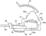
도 1 은 본 발명에 따른 음료 제조 머신 (2) 을 포함하는 음료 시스템 (1) 의 측면도를 도시한다. 머신 (2) 은 적어도 히터 (10), 펌프 (20) 및 제어 수단 (30) 을 담는 하우징 (2a) 을 포함한다. 게다가, 머신은 이 머신에 연결되는 리저버 (40), 추출 헤드 (50), 및 지지부 (예를 들어, 테이블) 상에 머신을 안정적으로 위치시키는 풋들이 바람직하게 형성된 베이스부 (2b) 를 포함한다. 머신은 컵 등의 용기 (R) 를 위한 스탠드 (2c) 를 더 포함하고, 이 스탠드는 용기가 위치되는 그리드 (2e) 가 형성된 상부면 (2d) 을 구비한다. 리저버 (40) 는 물 등의 액체를 히터 (10) 및 펌프 (20), 그리고나서 액체 순환 시스템을 통하여 머신 (2) 의 추출 헤드 (50) 에 공급한다. 바람직하게는, 리저버 (40) 는 머신에 분리가능하게 연결되고 또한 액체를 주입하기 위한 유입구 (40a) 를 가진다. 리저버 (40) 의 취급을 용이하게 하기 위해서 손잡이 (40b) 가 형성되는 것이 바람직하다. 따라서, 사용자는 리저버 (40) 를 편리한 방식으로 잡게 된다. 리저버 (40) 의 바닥에 바람직하게 위치된 유출구 (도면에 비도시) 는 리저버 (40) 와 머신 (2) 간에 연결부를 제공한다.1 shows a side view of a
일체형 리저버 (40) 이외에 또는 대안으로서, 외부 물 공급부가 제공될 수 있음을 알아야 한다.It should be appreciated that in addition to or as an alternative to the
머신의 추출 헤드 (50) 는, 머신에 제공된 원료 캡슐 (54) 을 선택적으로 둘러싸는 폐쇄 기구 (52) 및 차가운 물 또는 뜨거운 물을 추출 헤드 (50) 및 그리하여 캡슐 (54) 에 선택적으로 공급하기 위한 제어 레버 (56) 를 포함한다. 이와 연계하여, 제어 레버 (56) 는 머신 (2) 의 제어 수단 (30) 에 적어도 연결된다. 따라서, 제어 레버 (56) 는 중립 위치에서부터 뜨거운 물을 선택하는 제 1 위치 또는 차가운 물을 선택하는 제 2 위치로 전환시킬 수 있다. 이러한 선택은, 머신 (2) 의 전후방향으로 보았을 때, 제어 레버 (56) 를 좌측으로 또는 우측으로 이동시킴으로써 용이하게 할 수 있다. 따라서, 사용자는 차가운 음료 또는 뜨거운 음료를 제조하기 위해서 머신에 제공된 캡슐에 차가운 물 또는 뜨거운 물을 공급할지를 결정하여 선택할 수 있다.The
도 1 에서 볼 수 있는 바와 같이, 원료 캡슐 (54) 을 유지하기 위한 유지 수단 (60) 을 포함하는 캡슐 홀더 (58) 는 추출 헤드 (50) 의 수용 챔버 (64) (도 1 에 비도시) 에 수용되도록 추출 헤드 (50) 의 구멍 (62) 안으로 삽입된다. 그럼으로써, 캡슐 홀더는 머신에 분리가능하게 연결된다. 수용 챔버 (64) 에 접근가능한 구멍 (62) 은 추출 헤드의 전방측에 위치된다. 캡슐 (54) 을 수용하는 유지 수단 (60) 은 캡슐 (54) 의 음료 전달부 (54a), 예를 들어 유출 포트가 유지 수단에 둘러싸이지 않도록 구성된다.As can be seen in FIG. 1, a
캡슐 (54) 안으로 액체를 도입할 때, 자체 개방 하부면은 캡슐 (54) 내의 압력 상승으로 인해 캡슐에서 개방하여, 예를 들어 캡슐 (54) 하부에 배치된 용기 (R) 에 음료를 제공한다. 더욱이, 캡슐 홀더 (58) 의 편리한 취급을 가능하게 하도록 이 캡슐 홀더 (58) 에 손잡이 (66) 가 연결된다. 게다가, 캡슐 홀더 (58) 에는 전방 커버 (68) 가 장착되어, 이 전방 커버는 캡슐 홀더 (58) 가 구멍에 삽입되면 이 구멍 (62) 을 덮는다.When introducing liquid into the
도 2 에 개략적으로 도시된 바와 같이, 추출 헤드 (50) 는 그 사이에 연결되는 주입 부재 (70) 와 지지부 (80) 를 포함하고, 이 둘 다 추출 헤드 내부에 위치된다. 주입 부재 (70) 와 지지부 (80) 간의 연결은 공지된 방식으로, 예를 들어 본원에 참조된 EP 2,071,988 A1 에 개시된 바와 같은, 연결 기구를 통하여 형성될 수 있다.As schematically shown in FIG. 2, the
폐쇄 기구 (52) 는 지지부 (80) 와 수용 챔버 (64) 의 후방벽 (64a) 간의 상대 운동을 가능하게 한다. 지지부 (80) 는 하부로부터 추출 헤드의 돔 형상의 부재 (50a) 에 연결된다. 폐쇄 기구 (52) 는 사용자에 의해 작동되어 하강되면, 지지부 (80) 는 상승되거나 높은 개방 위치 (도 2 에 도시) 로부터 추출 헤드 (50) 내부에 제공된 안내 리세스 (64b) 쪽으로 하강된다. 이러한 안내 리세스 (64b) 는, 수용 챔버 (64) 안으로 슬라딩하여 삽입될 때 캡슐 홀더를 안내하고 또한 상기 캡슐 홀더 (58) 를 수용 챔버 (64) 내의 정확한 위치에 유지하도록 구성된다. 따라서, 캡슐 홀더 (58) 에 의해 유지되는 캡슐 (54) 은 폐쇄 기구 (52) 덕분에 수용 챔버 (64) 내에서 효율적으로 둘러싸여질 수 있다.The
도 3 은 도 2 의 주입 부재 (70) 와 지지부 (80) 의 확대 단면도를 도시한다.3 shows an enlarged cross-sectional view of the
도 3 에 도시된 바와 같이, 주입 부재 (70) 는 본 출원인의 유럽특허 EP 1,967,100 B1 에 개시된 바와 같이, 원료 캡슐 (54) (도 2 참조) 을 천공 또는 구멍뚫는 천공 또는 구멍뚫기 부재 (74) 를 구비하는 천공 및 주입 유닛 (73) 을 포함한다. 부재 (74) 는 스테인리스 강 또는 세라믹 재료로 제조된 니들이다.As shown in FIG. 3, the
천공 및 주입 유닛 (73) 은 적어도 하나의 내부 관통 채널 (75) 을 더 구비하고, 이 내부 관통 채널은, 천공 부재의 일 단부 (74a) 에 대응하는 유입 오리피스 (75a) 로부터 천공 또는 구멍뚫기 기능을 실시하도록 구성된 반대편 단부 (74b) 에 대응하는 유출 오리피스 (75b) 까지 연장한다.The puncturing and injecting
채널은 펌프 (20) 에 의해 추출 헤드 (50) 에 공급되는 물 등의 액체를 천공 후에 원료 캡슐 (54) 안으로 주입하는데 사용된다. 액체는 유입 오리피스 (75a) 에서 도입되고 채널 내에서 캡슐의 내부 (도 3 에는 비도시) 와 연통하는 유출 오리피스 (75b) 까지 관류한다.The channel is used to inject a liquid, such as water, supplied to the
전술한 바와 같은 천공 및 주입 유닛 (73) 은 도 4a 및 도 4b 에 보다 자세히 도시되었고, 예를 들어 니들 요소의 형태를 취한다. 니들 요소는 스테인리스 강으로 제조되는 것이 바람직하다. 니들 요소는 베이스 플레이트의 상부 수평면 (76a) 에 동일 평면에 장착되어 하부면 (76b) 으로부터 돌출하도록 이 베이스 플레이트 (76) 의 횡방향 홀에 압입되었다.The perforation and
주입 유닛 (43) 은 원료 캡슐을 반드시 천공하지 않지만 캡슐에 제공된 구멍 또는 유입 포트를 통하여 끼워질 수 있음을 알아야 한다. 이에 대하여, 주입 기능을 실시하는 주입 유닛 (73) 은 다른 형태를 취할 수 있다. 대안으로서, 캡슐은 어떠한 다른 수단에 의해 천공될 수 있고, 또한 다른 형태를 취할 수 있는 주입 유닛 (73) 은 주입 기능만을 실시한다.It should be noted that the injection unit 43 does not necessarily puncture the raw capsule but can be fitted through a hole or inlet port provided in the capsule. In contrast, the
베이스 플레이트 (76) 는 예를 들어 실질적으로 디스크 형상이다. 베이스 플레이트 (76) 는, 예를 들어 도 3 에 도시된 종방향 단면에서 실질적으로 역 U 형상을 가진다. 역 U 형상은 상부면 (76a) 과 함께 내부 리세스를 구획하는 주변의 둘레 가장자리 (76c) 에 의해 한정된다.
지지부 (80) 는 내부 리세스안으로 내부에 위치된 지지 플레이트를 포함한다. 예를 들어, 주입 부재는 고무 기재의 재료로 제조되고 또한 지지 플레이트 (80) 에 성형 (예를 들어, 사출 성형) 될 수 있다. 도 3 에서 볼 수 있는 바와 같이, 지지 플레이트 (80) 는 베이스 플레이트 (76) 위에 위치되고 또한 도면에 도시되지 않은 방식으로 도 2 의 추출 헤드 (50) 에 연결될 수 있다.The
베이스 플레이트 (76) 는, 니들 요소 (73) 가 결합되는 횡방향 홀 근방에서, 상부면 (76a) 에서부터 종축선 (Z) 을 따라 축방향으로 연장하는 융기부 (76d) 를 또한 포함한다.The
융기부 (76d) 는, 상단부로부터 횡방향으로, 이 상부면 (76a) 으로부터 거리를 두고, 니들 요소의 횡방향 홀이 통과하는 종축선 (Z) 둘레에 동심으로 배열된 실질적으로 링형상의 연장부 (76e) 를 통하여 더 연장한다.The
도 3 에서 볼 수 있는 바와 같이, 링 형상의 연장부 (76e) 는 일 단부에서 융기부 (76d) 의 상단부에 고정되고 타 단부에서 자유롭게 된다. 링 형상의 연장부 (76e) 는 기밀 밀봉 기능을 가진다.As can be seen in FIG. 3, the ring-shaped
머신은 주입 부재 (70) 및 니들 요소에 대향하여 위치된 세척 장치 (90) 를 더 포함한다. 도시된 실시형태에 있어서, 배열된 세척 장치 (90) 는 니들 요소 위에 있고 또한 지지 플레이트 (80) 와 접촉하는 중공 케이싱 (92) 에 수용된다. 보다 자세하게는, 케이싱은 지지 플레이트 (80) 의 상부면 (80a) 에 고정되는 반면, 그의 하부면 (80b) 은 베이스 플레이트 (76) 의 상부면 (76a) 과 접촉한다.The machine further includes a
케이싱 (92) 은, 종축선 (Z) 을 따라 기다랗고 또한 니들 요소 횡방향 홀이 통과하는 상기 종축선 (Z) 둘레에 동심으로 배열된 형상을 가진다.The
케이싱 (92) 은 실질적으로 원통 형상이지만 다른 형상을 상정할 수 있다.The
케이싱 (92) 은 세척 장치 (90) 를 통하여 삽입하기 위해 케이싱의 하나의 상단부 (92b) 에서 개방되는 기다란 내부 공동 (94) 을 둘러싸는 본체 (92a) 를 구비한다. 폐쇄 부재 (97), 예를 들어 캡은 케이싱을 일시적으로 폐쇄하도록 상단부 케이싱상에 단단하고 해제가능한 방식으로 장착된다.The
케이싱은 반대편 하단부에 큰 상부 개구 (92b) 에 비하여 작은 개구 (92c) 를 가진다.The casing has a
케이싱 (92) 은 또한 그 본체 (92a) 로부터 축방향으로 또한 횡방향으로 둘 다 연장하는 베이스부 (92d) 를 구비하여, 숄더를 형성한다.The
개략적으로 도시된 바와 같이, 베이스부 숄더는 1 개 또는 여러 개의 탄성 유지 부재 (96) 아래에 결합되고, 이 탄성 유지 부재는 상부면 (80a) 의 주변부로부터 융기되어 그로부터 내부로 돌출한다. 그리하여, 케이싱 (92) 은 상부면 (80a) 에 대하여 그 위치에 단단히 유지된다.As schematically shown, the base shoulder is coupled under one or several
더욱이, 중심의 내부 리세스 (92e) 는 하부로부터 베이스부 (92d) 에 제공된다.Moreover, a central
이러한 리세스는 개구 (92c) 를 중심으로 중심맞춰지고 또한 이 개구와 연통한다.This recess is centered about and in communication with the
리세스 (92e) 의 내부 치수는 돌출부 (6e) 의 외부 치수와 맞춰져서, 돌출부가 리세스에 꽉 결합하거나 스냅결합될 수 있다.The internal dimension of the
돌출부 (76e) 를 케이싱 (92) 의 리세스 (92e) 안으로 삽입하기 전에, 플러그 부재 (98) 는 하부로부터 링 형상의 돌출부 (76e) 의 중심 구멍안으로 스냅결합되거나 압입된다. 이러한 플러그 부재는 액밀 기능 (liquid-tight function) 을 실시하고 또한 그 중심부에 내부 관통 덕트를 구비한다. 내부 관통 덕트는 니들 요소 (73) 의 내부 관통 채널 (75) 과 정렬된다.Before inserting the
베이스 플레이트 (76) 의 리세스내에서 지지 플레이트 (80) 를 배열하기 전에, 안내 부재 (99) 는 그 전체 두께에서 지지 플레이트 (80) 를 횡단하는 홀안으로 삽입된다.Before arranging the
안내 부재 (99) 는, 지지 플레이트 (80) 가 베이스 플레이트 리세스내에 수용될 때 플러그 부재 (98) 의 내부 관통 덕트 및 니들 요소 (73) 의 내부 관통 채널 (75) 과 정렬되는 관통 중심 덕트를 구비한다. 안내 부재 (99) 는 예를 들어 실질적으로 원통 형상이다.The
케이싱 (92) 에는 압력하의 액체를 내부 공동 (94) 안으로 도입할 수 있는 적어도 하나의 유입 개구가 또한 제공된다. 도 3 에 도시된 실시형태에 있어서, 케이싱 (92) 에는, 벽 구성 본체 (92a) 로부터 외부로 돌출하는 덕트 형태를 각각 취하는 2 개의 별개의 유입 개구 (92f, 92g) 가 제공된다. 덕트 (92f, 92g) 는 벽을 통하여 내부 공동 (94) 으로 나타난다.The
도 3 에 도시된 바와 같이, 덕트 둘 다는 조립체 (케이싱 (92) 을 갖춘 지지 플레이트 (80) 와 주입 부재 (70)) 의 전체 크기를 증가시키지 않도록 지지 플레이트 (80) 의 중심부 위의 케이싱의 동일측에 위치된다.As shown in FIG. 3, both ducts are identical to the casing on the central portion of the
더욱이, 덕트들 중 하나는 다른 덕트 위에 배열된다. 덕트들 중 하나는 뜨거운 액체 (예를 들어, 물) 용으로 사용되는 반면, 다른 덕트는 주변 온도에서 액체 (예를 들어, 물) 용으로 사용된다. 이러한 덕트들은 액체 순환 시스템을 통하여 펌프 (70) 와 연통하게 된다.Moreover, one of the ducts is arranged above the other duct. One of the ducts is used for hot liquid (eg water), while the other duct is used for liquid (eg water) at ambient temperature. These ducts are in communication with the
세척 장치 (90) 는 도 4a 및 도 4b 에 개략적으로 도시된 바와 같이 2 개의 메인 위치들 사이에서 종축선 (Z) 을 따라 이동가능한 지지 부재 (100) 를 포함한다. 보다 자세하게는, 지지 부재는 기다란 내부 공동 (94) 내에서 슬라이딩가능하다. 세척 장치 (90) 는 또한 지지 부재 (100) 에 연결되어 이 지지 부재와 함께 이동하는 기다란 세척 부재 (102) 를 포함한다.The
기다란 세척 부재 (102) 는 지지 부재에 분리가능하게 연결될 수 있거나 일방의 단부에 의해 지지 부재에 영구적으로 고정되며, 타방의 단부는 자유롭다.The
기다란 세척 부재 (102) 는, 예를 들어 핀 형태를 취할 수 있다.The
기다란 세척 부재 (102) 는 내부 채널 (75) 의 형상 및 내부 치수 (예를 들어, 내경) 와 각각 맞춰지는 형상 및 외부 치수를 가진다.The
따라서, 세척 부재 (102) 는 세척 목적용으로 머신을 사용하는 중에 채널 (75) 내에서 전후 운동을 따를 수 있다.Thus, the cleaning
세척 부재 (102) 의 형상 및 외부 치수는 또한 세척 부재 (102) 의 슬라이딩 운동을 향상시키도록 플러그 부재 (98) 및 안내 부재 (99) 의 형상 및 내부 치수와 각각 맞춰짐을 알 수 있다.It can be seen that the shape and external dimensions of the cleaning
특히, 안내 부재 (99) 는 채널 (75) 과의 슬라이딩 운동중 세척 부재 (102) 를 종방향으로 안내한다.In particular, the
지지 부재 (100) 는 슬라이딩 용도로 내부 공동 (94) 의 치수와 꼭 맞춰지는 치수의 실질적으로 원통형 외부 형상을 가진다.The
지지 부재 (100) 는 이 지지 부재로부터 축방향으로 연장하는 본체부 (100a) 또는 연장부의 축방향을 가로질러 지지 부재의 폐쇄 단부 (하단부) 를 형성하는 베이스부 (100b) 를 포함한다.The
도 3 의 실시형태에서, 축방향 연장부는 수직한 종축선 (Z) 을 따른다. 하지만, 도 3 의 조립체 (주입 부재 (70) 및 세척 장치 (90)) 의 다른 기하학적 배열도 상정할 수 있다. 예를 들어, 종축선 (Z) 은 수평일 수 있거나 또는 수평 방향 및 수직 방향 사이에서 경사질 수 있다.In the embodiment of FIG. 3, the axial extension follows the vertical longitudinal axis Z. However, other geometric arrangements of the assembly (
기다란 세척 부재 (102) 는 지지 요소 (100b) 에 고정된 일 단부를 가진다. 이 단부는 횡방향 지지 요소 (100b) 에 형성된 구멍안으로 압입될 수 있다.The
본체부 (100a) 는, 지지 부재의 반대편 개방 단부 (상단부) 에 도달할 때까지 축방향으로 계속 연장하면서, 횡방향 지지 요소 (100b) 로부터 거리를 두고 반경방향으로 또는 횡방향으로 연장한다.The
반경방향 또는 횡방향 연장부는 숄더 (100c) (즉 횡방향 요소) 를 형성하고, 그리하여 이 숄더는 본체 벽 (92a) 의 내부면과 숄더 아래에 위치된 본체부 (100a) 의 일부 사이의 간격 (104) 에서 자유롭다. 이러한 본체부 (100a) 의 일부는 숄더 (100c) 보다 좁은 횡방향 치수를 가진다.The radial or transverse extension forms a
이 실시예에서, 간격 (104) 은 환형의 원통형부 형태를 취한다.In this embodiment, the spacing 104 takes the form of an annular cylindrical section.
도 3 에 도시된 바와 같이, 지지 부재의 최저 위치에서, 숄더 (100c) (횡방향 요소) 는 돌출하는 최고 덕트 (92g) 위에 위치된다.As shown in FIG. 3, at the lowest position of the support member, the
이러한 배열은, 지지 부재의 위치가 무엇이든지 유입 덕트 (92g) 를 통하여 도입된 액체가 간격 (104) 과 항상 연통함을 보장해준다.This arrangement ensures that the liquid introduced through the
지지 부재의 기다란 본체부 (100a) 는 중공이고 또한 내부 하우징 (100d) 을 가진다.The
내부 하우징 (100d) 은 횡방향 지지 요소 (100b) 의 내부면 (100e) 에 의해 일방의 단부 (하단부) 에서 구획되고 또한 내부 공동 (94) 과 연통하도록 타방의 단부 (상단부) 에서 개방된다.The
하우징 (100d) 은 예를 들어 원통형 형상이다.The
세척 장치 (90) 는 지지 부재 (100) 상에 제 1 미리 정해진 힘 (F1) 을 영구적으로 가하는 작용 수단 (active means) 을 더 포함한다.The
상기 힘 (F1) 은 종축선 (Z) 을 따라서 도 3, 도 4a 및 도 4b 에 도시된 바와 같이 하방으로 배향된 방향으로 가해진다.The force F1 is applied along the longitudinal axis Z in a downwardly oriented direction as shown in FIGS. 3, 4A and 4B.
작용 수단은 도면에서 스프링 수단 (106) 등의 탄성 수단인 것이 바람직하다. 하지만, 대안으로서 동일한 역할을 하는 다른 작용 수단이 사용될 수 있다. 예를 들어, 압력하에서 하우징 (100d) 내에 유체를 주입하는데 적합한 공압 수단 또는 주입 수단을 상정할 수 있다.The acting means is preferably elastic means such as spring means 106 in the figure. As an alternative, however, other means of action may be used which serve the same role. For example, one can assume pneumatic means or injection means suitable for injecting fluid into the
이러한 유체는 리저버 (40) 로부터 추출된 물일 수 있다.Such fluid may be water extracted from
도 3 의 실시형태에서, 스프링 수단 (106) 은 일방의 단부에 의해 내부면 (100e) 에 고정되고 또한 타방의 단부에 의해 폐쇄 부재 (97) 의 내부면에 고정된다.In the embodiment of FIG. 3, the spring means 106 is fixed to the
도 3 에 도시된 위치에서, 내부면 (100e) 에 가해진 제 1 영구적인 힘 (F1) 은 주입 액체 (예를 들어, 물) 가 없을 시에 어떠한 대향력에 의해 보상되지 않는다.In the position shown in FIG. 3, the first permanent force F1 exerted on the
그리하여, 지지 부재 (100) 는 최저 위치 (또한 도 4b 참조) 를 차지하도록 가압되어, 기다란 세척 부재 (102) 를 세척 용도로 채널 (75) 안으로 삽입하도록 가압한다 (제 1 작용 위치).Thus, the
세척 부재 (102) 의 길이는 도 3 및 도 4b 에서 유출 오리피스 (75b) 에 도달할 수 있도록 적절한 크기로 되어야 함을 알아야 한다.It should be noted that the length of the cleaning
하지만, 사용자가 원료 캡슐을 머신안에 삽입한 후 음료 제조 머신을 조작하면, 추출 헤드 (50) 의 폐쇄 기구 (52) 는 지지부 (80) 및 주입 부재 (70) 를 포함하는 조립체를 하강시켜 머신을 폐쇄하도록 폐쇄 위치로 가게 된다. 그 후, 사용자는 작동 버튼 또는 부재를 누름으로써 및/또는 제어 레버 (56) 를 조작함으로써 및/또는 어떠한 다른 작동 또는 작용 수단을 통하여 머신을 작동시킨다. 그 후, 액체, 예를 들어 물은 액체 공급원 또는 리저버 (40) 로부터 액체를 펌핑하는 펌프 (20) 덕분에 머신의 액체 순환 시스템내에서 순환하게 된다. 그리하여, 액체는 사용자의 선택 (뜨거운 온도의 음료 또는 주변 온도의 음료) 에 따라서 2 개의 덕트 (92f, 92g) 중 하나로 가게 된다.However, if the user operates the beverage preparation machine after inserting the raw capsule into the machine, the
그 후, 압력하의 액체는 간격 (104) (도 3) 안으로 도입되어 이 간격을 채운다.Thereafter, the liquid under pressure is introduced into the gap 104 (FIG. 3) to fill this gap.
따라서 간격 (104) 이 채워지고 또한 액체가 유입 덕트로부터 계속 유동하면, 간격내의 액체의 압력은 증가하고, 특히 숄더 (100c) 에 의해 형성된 횡방향 요소에 작용하여, 지지 부재 (100) 를 상승시킨다.Thus, if the
액압은 제 1 미리 정해진 힘 (F1) 에 대향하고 또한 지지 부재 (100) 를 상방으로 밀기에 충분히 높다.The hydraulic pressure is high enough to oppose the first predetermined force F1 and to push the
내부면 (100e) 반대편의 횡방향 지지 요소 (100b) 의 외부면 (100g) 이 유출 개구 (92c) 로부터 이간되면, 압력 액체는 또한 외부면 (100g) 에 대하여 가해지고 또한 지지 부재 (100) 를 그 휴지 위치 (도 4a) 쪽으로 이동시키는데 기여한다.When the
도 4a 에 도시된 바와 같이, 액압은 외부면 (100g) 과 숄더 (100c) 둘 다에 작용하고, 이는 대향력 (F2) (종방향으로 배향됨) 으로 개략적으로 도시되어 있다. 힘 (F2) 은 힘 (F1) 보다 크다.As shown in FIG. 4A, the hydraulic pressure acts on both the
지지 부재 (100) 의 종방향 이동 중에, 기다란 세척 부재 (102) 는 내부 관통 채널 (75) 을 통하여 점점 인출된다. 이러한 인출로 인해 세척 부재 (102) 가 채널 (75) 의 내부면에 대하여 문질러질 수 있다.During the longitudinal movement of the
세척 부재 (102) 가 채널 (75) 및 유출 개구 (92c) 로부터 완전히 제거되면, 액체 (예를 들어, 물) 는, 도면에 도시되지 않은 원료 캡슐안으로 주입하기 위한 채널 (75) 에 도달하기 전에, 유출 개구 및 부재 (98, 99) 의 연속 덕트에 도입된다.Once the cleaning
도 4a 에 도시된 바와 같이, 휴지 위치에서, 세척 부재 (102) 는 더 큰 힘 (F2) 덕분에 스프링 수단 (106) 을 압축하는 액압을 통하여 채널 (75) 외부에 유지된다.As shown in FIG. 4A, in the rest position, the cleaning
(머신 조작의 종료시) 액체 주입이 정지되면, 액압은 급속히 감소하고, 그리하여 제 1 미리 정해진 힘 (F1) 이 액압으로 인한 힘을 초과할 수 있다. 그 후, 지지 부재 (100) 는 힘 (F1) 의 작용하에서 하방으로 이동되고 (도 4b), 세척 부재 (102) 는 채널 (75) 을 통하여 밀려져서 출구 오리피스 (75b) 까지 밀려진다.When the liquid injection is stopped (at the end of the machine operation), the hydraulic pressure decreases rapidly, so that the first predetermined force F1 may exceed the force due to the hydraulic pressure. Thereafter, the
채널 (75) 내에서의 슬라이딩 운동시, 세척 부재 (102) 는 그 내부면과 접촉하고 그리하여 채널 내부에 축적될 수 있는 어떠한 가능한 퇴적물, 폐기물 (예를 들어, 스케일링 퇴적물) 을 제거할 수 있다.During sliding movement in the
도 4b 에 도시된 위치에서, 세척 부재 (102) 는 출구 오리피스 (75b) 에 도달하고 또한 머신의 후속 조작때까지 채널 내부에 있을 것이다. 이는 머신이 휴지 상태일 때 세척 부재의 존재로 인해 채널 내부에 퇴적물이 형성될 수 없는 추가의 장점을 제공한다.In the position shown in FIG. 4B, the cleaning
도 4a 및 도 4b 에서, 지지부 (80) 는 명확성을 위해 점선으로 개략적으로 도시하였다.4A and 4B, the
추가의 적합한 밀봉 수단 (도면에 비도시) 은 도 3 에 도시된 조립체의 상이한 부분들 사이의 어떠한 액체 누출을 방지하도록 사용될 수 있다.Further suitable sealing means (not shown) can be used to prevent any liquid leakage between the different parts of the assembly shown in FIG. 3.
이하, 음료 제조 머신 (200) 및 이와 관련된 시스템의 다른 실시형태는 도 5 ~ 도 7 을 참조하여 설명될 것이다.Other embodiments of the
도 1 및 도 2 와 관련된 전술한 설명은 여기에서 적용가능하고 또한 반복하지 않을 것이다.The foregoing descriptions in connection with FIGS. 1 and 2 are applicable here and will not be repeated.
도 1 및 도 2 에 속하는 도면부호는, 변형된 주입 부재 (70) 및 세척 장치 (90) 를 제외하고, 이 도면에서 대체되는 동일한 요소들을 나타낸다.1 and 2 represent the same elements that are replaced in this figure, except for the modified
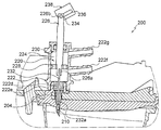
도 5 는, 추출 헤드가 개방된 높은 위치에 있을 때, 도 2 의 추출 헤드 (50) 의 내부의 확대 부분 단면도를 나타낸다. 상기 위치에서, 음료 제조 머신은 원료 캡슐이 구멍 (62) (도 2) 을 통하여 도입될 수 있도록 개방된다. 도 7 은 머신의 폐쇄 위치를 도시한다.FIG. 5 shows an enlarged partial sectional view of the inside of the
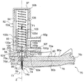
도 5 에 도시된 바와 같이, 변형된 주입 부재 (202) 는 주입 부재 (70) 및 지지부 (80) 에 대하여 전술한 바와 같이 동일한 방식으로 지지부 (80) 에 연결된다.As shown in FIG. 5, the modified
주입 부재는 조립된 주입 베이스 플레이트 (206) 및 지지 플레이트 (80) 의 전체 두께에 걸쳐 연장하는 천공 및 주입 유닛 (204) 을 포함한다.The injection member includes a perforated and
천공 및 주입 유닛 (204) 은 도 2 에서 캡슐 (54) 등의 원료 캡슐을 천공하기 위한 천공 부재 (208) 를 구비한다.The puncturing and injecting
천공 부재 (208) 의 기능은 캡슐의 벽에 홀 또는 구멍 (또는 여러 개의 홀들 또는 구멍들) 을 형성하도록 하여, 이러한 홀이 상기 캡슐안으로 액체를 주입할 수 있다. 상기 홀 또는 구멍 (또는 상기 홀들) 은 구멍뚫기, 인열 수단 등의 어떠한 다른 수단에 의해 형성될 수 있다 (이러한 설명은 도 1 내지 도 4b 를 참조하여 기재된 실시형태에도 적용).The function of the
또한, 유닛 (204) 은 대안적으로 원료 캡슐안으로 홀 또는 구멍을 형성하는데 반드시 사용되지 않지만 상기 캡슐내에 이미 제공된 홀, 구멍 또는 유입 포트를 통하여 끼워맞춰질 수 있다.In addition,
이러한 환경에서, 주입 기능만을 실행하는 주입 유닛 (204) 은 다른 형태 (도관, 파이프, 노즐 등) 를 취할 수 있다.In such an environment, the
대안으로, 여기에서 주입 기능만을 실행하는 다른 형태를 취할 수 있는 어떠한 다른 별개의 수단 및 주입 유닛 (204) 에 의해 천공, 구멍뚫기, 인열 등으로 될 수 있다.Alternatively, it may be perforated, perforated, teared, etc. by any other separate means and
천공 및 주입 유닛 (204) 은 또한 천공 후에 원료 캡슐안으로 펌프 (20) 에 의해 추출 헤드 (50) 에 공급되는 액체를 주입하는데 사용되는 적어도 하나의 내부 관통 채널 (210) 을 또한 구비한다.The puncturing and injecting
도 6 은, 본원에서 예를 들어 니들 요소 형태를 취하는 유닛 (204) 의 단면의 상세도를 도시한다.6 shows a detailed view of a cross section of a
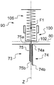
도시된 바와 같이, 유닛 (204) (니들 요소) 은 3 개의 채널부 (210a ~ 210c) 를 포함하고, 이 채널부는 채널 (210) 을 이하로 분리시킨다:As shown, the unit 204 (needle element) includes three
- 액체가 상기 채널을 나가고 또한 원료 캡슐에 들어가는 (액체는 제 1 채널부 (210a) 의 소직경 (d1) 으로 인해 제트 형태하에서 자유 단부 (210d) (유출 오리피스) 로부터 배출) 채널 (210) 의 자유 돌출 단부 (210d) 를 포함하는 제 1 채널부 (210a) 로서; 제 1 채널부의 길이는 특히 막힐 위험을 저감시키기 위해서 가능한 한 작아야 하는, 제 1 채널부 (210a);The liquid 210 exits the channel and also enters the raw capsule (the liquid exits from the
- 제 1 채널부 (210a) 상류측에 배열되고 또한 확대된 제 2 내경 (d2) 을 가지는 제 2 중간 채널부 (210b) 로서; 제 2 채널부 (210b) 의 길이는 제 1 채널부 (210a) 의 길이보다 크고, 유닛 (204) 의 외경 (D1) 은 제 1 채널부 (210a) 및 제 2 채널부 (210b) 를 따라 동일하게 남아 있는, 제 2 중간 채널부 (210b);As a second
- 제 2 채널부 (210b) 상류측에 배열되고 또한 액체가 채널안으로 침투하는 유입 오리피스가 위치되는 채널의 반대편 단부 (210c) 를 포함하는 제 3 채널부 (210c) 로서; 이 제 3 채널부는 확장된 제 3 내경 (d3) 및 확장된 외경 (D2) 을 가지고, 또한 제 2 채널부보다 큰 길이를 가지는, 제 3 채널부 (210c).As a
자유 돌출 단부에 근접하는 유닛 (204) 의 외경 (D1) 은 충분히 작고, 이 외경이 유지되는 상기 부재의 길이는, 천공, 구멍뚫기 등을 통하여 원료 캡슐의 벽에 홀 또는 구멍을 효과적으로 형성하기에 충분히 길다. 제 2 중간 채널부 및 제 3 채널부가 없다면, 천공 부재의 외경은 제 1 채널부의 상류측 단부에서 천공 부재의 외경이 D2 와 동일하다. 이는 덜 효과적인 천공 부재를 유발한다. 하지만, 제 2 중간 채널부가 생략될 수 있다. 이러한 경우에, D2 와 동일한 외경을 가진 천공 부재의 일부는 길 수 있거나 또는 대안으로 제 1 채널부 (210a) 의 길이는 외경 (D1) 을 가진 천공 부재와 동일한 길이를 유지하도록 더 길 수 있다.The outer diameter D1 of the
예를 들어, 내경 (d1, d2, d3) 은 각각 0.6 ㎜, 0.8 ㎜ 및 1.8 ㎜ 대응할 수 있고, D1 은 1.5 ㎜ 에 대응하고 D2 는 2.6 ㎜ 에 대응하며, 제 3 채널부 (210c) 의 길이 (L1) 는 5 ㎜ 에 대응하며, 길이 (L2, L3) 는 각각 8.9 ㎜ 및 12 ㎜ 이다. 니들 요소 (204) 는 바람직하게는 스테인리스 강으로 제조된다.For example, the inner diameters d1, d2, d3 may correspond to 0.6 mm, 0.8 mm and 1.8 mm, respectively, D1 corresponds to 1.5 mm and D2 corresponds to 2.6 mm, and the length of the
도 6 에 도시된 바와 같이, 확장된 외경 (D2) 을 가진 천공 부재의 일부는 도 5 및 도 7 의 지지 플레이트 (80) 에 제공된 관통 홀안으로 삽입되기에 충분히 강성이다. 천공 부재의 외부면에 배열된 돌출 요소는 유지 요소로서 작용할 것이다.As shown in FIG. 6, a portion of the perforation member having the expanded outer diameter D2 is rigid enough to be inserted into the through hole provided in the
도 6 에 도시된 천공 및 주입 유닛 (204) 은, 홀이나 구멍이 원료 캡슐 (예를 들어, 그의 벽) 에 형성되어야 하고 또한 액체가 관통하여 주입되어야 하는 어떠한 다른 종류의 음료 제조 머신에 사용될 수 있다. 도 1 및 도 2 에 도시된 머신은, 분리가능한 연결부 또는 그렇지 않은 연결부에 천공 및 주입 유닛 등을 포함하는데 특히 적합하다.The perforation and
하지만, 상이한 기구 및 형상을 가진 어떠한 다른 유형의 머신이 편리할 수 있다.However, any other type of machine with different mechanisms and shapes may be convenient.
도 5 로 되돌아가면, 설치된 유닛 (또는 니들 요소) (204) 이 지지 플레이트 (80) 의 상부면 (80a) 상에 동일 평면에 장착되도록 배열되고 또한 주입 부재 (202) 의 하부면 (202a) 으로부터 돌출한다.Returning to FIG. 5, the installed unit (or needle element) 204 is arranged to be mounted coplanar on the
머신 (200) 은, 주입 부재 (202) 및 유닛 (204) 에 대향하고 또한 이들 위에 위치되는 세척 장치 (220) 를 더 포함한다.The
도시된 바와 같이, 세척 장치 (220) 는 유지 수단을 통하여 지지 플레이트 (80) 의 상부면 (80a) 과 접촉하여 유지되는 중공 케이싱 (222) 내에 수용된다. 예를 들어, 케이싱 (222) 의 외부면에 형성되는 숄더 (222a, 222b) 는 케이싱 (222) 을 위치에 유지하기 위해 추출 헤드 (50) 의 구조적 수단과 상호 협력한다.As shown, the
케이싱 (222) 은 종축선을 따라 기다랗고 또한 니들 요소 횡단 홀에 의해 통과하는 상기 축선 둘레에 동심으로 배열되는 형상을 가진다.The
케이싱 (222) 은 실질적으로 원통 형상이지만 다른 형태도 상정할 수 있다.The
케이싱 (222) 은 세척 장치 (220) 를 관류 삽입하기 위한 케이싱의 하나의 상단부 (222b) 에서 개방하는 기다란 내부 공동 (224) 을 둘러싸는 본체 (222a) 를 구비한다.The
케이싱 (222) 은 그 하단부에 베이스부 (222c) 를 구비한다. 중심 관통 홀 (222d) (도 7) 은 케이싱의 연장부와 내부 공동 (224) 간의 연통을 허용하도록 베이스부에 형성된다. 환형 리세스 (222e) 는 하부로부터 베이스부 (222c) 에 제공되고 또한 홀 (222d) 을 둘러싼다. 예를 들어, 환형의 원통형부의 형상인 환형의 리세스 (22e) 는 기밀 밀봉 기능을 가지는 도 3 의 돌출부 (76e) (링 형상부) 를 수용한다. 관통 홀 (222d) 은 니들 요소 (204) 의 내부 관통 채널 (210) 과 정렬된다.The
케이싱 (222) 에는 또한 압력하의 액체를 내부 공동 (224) 에 도입할 수 있는 적어도 하나의 유입 개구가 형성된다. 도 5 및 도 7 에 도시된 실시형태에서, 케이싱 (222) 에는 벽 구성 본체 (222a) 로부터 외부로 돌출하는 덕트 형태를 각각 취하는 2 개의 별개의 유입 개구 (222f, 222g) 가 형성된다. 덕트 (222f, 222g) 는 벽을 통하여 내부 공동 (224) 안으로 돌출한다.Casing 222 is also formed with at least one inlet opening through which pressure can be introduced into the
도 5 및 도 7 에 도시된 바와 같이, 양 덕트는 조립체 (주입 부재 (202) 및 세척 장치를 둘러싸는 케이싱 (222)) 의 전체 크기를 증가시키지 않도록 지지 플레이트 (80) 의 중심부 위에 케이싱의 동일측에 위치된다.As shown in FIGS. 5 and 7, both ducts are identical to the casing above the center of the
더욱이, 덕트들 중 하나는 다른 덕트 위에 배열된다. 덕트들 중 하나는 뜨거운 액체 (예를 들어, 물) 를 위해 사용되는 반면, 다른 덕트는 주변 온도에서 액체 (예를 들어, 물) 을 위해 사용된다. 이러한 덕트는, 예를 들어 가요성 파이프를 포함하는 액체 순환 시스템을 통하여 펌프 (20) (도 1) 와 연통한다.Moreover, one of the ducts is arranged above the other duct. One of the ducts is used for hot liquid (eg water) while the other duct is used for liquid (eg water) at ambient temperature. This duct is in communication with the pump 20 (FIG. 1) via a liquid circulation system comprising, for example, a flexible pipe.
세척 장치 (220) 는 도 5 및 도 7 에 개략적으로 도시된 바와 같이 2 개의 메인 위치들 사이에서 케이싱 (222) 의 종축선을 따라 이동가능한 지지 부재 (226) 를 포함한다. 보다 자세하게는, 지지 부재 (226) 는 안내 부재 (228) 를 통하여 기다란 내부 공동 (224) 내에서 슬라이딩가능하다. 안내 부재는, 예를 들어 종방향 형상의 지지 부재 (226) 둘레에 장착하기 위한 중심 홀을 가진 링 형상을 가진다. 안내 부재 (228) 에는 액체가 관통할 수 있는 횡방향 홀이 제공된다. 더욱이, 안내 부재는 지지 부재가 감소된 부분으로 인해 숄더를 가지는 영역에서 지지 부재 (226) 둘레에서 조절된다. 안내 부재 (228) 의 외경은 슬라이딩 용도로 내부 공동의 치수와 끼워맞춰진다.The
지지 부재 (226) 는 그 상단부에서 케이싱 (222) 으로부터 돌출한다. 폐쇄 부재 (230) 는 케이싱 (222) 의 개방 상단부를 폐쇄하고 또한 그 내부에 지지 부재 (226) 를 수용하여 이 지지 부재가 관통하여 슬라이딩 운동을 하도록 중심 내부 홀을 구비한다. 폐쇄 부재는, 예를 들어 지지 부재 (226) 와 접촉하는 내부 주변 밀봉부 (예를 들어, O-링, 쿼드-링, 더블 델타 밀봉부 등) 를 가진 플랜지이다. 폐쇄 부재는 케이싱상에 단단히 또한 분리가능하게 공지된 방식으로 장착된다.The
세척 장치 (220) 는 또한 지지 부재 (226) 에 연결되어 이 지지 부재와 함께 이동하는 기다란 세척 부재 (232) 를 포함한다.The
기다란 세척 부재 (232) 는, 지지 부재의 일 단부에 분리가능하게 연결되거나 또는 일방의 단부에 의해 지지 부재에 영구적으로 고정될 수 있으며, 반대편 기다란 세척 부재의 단부는 자유롭다. 예를 들어, 부재 (232) 는 감소된 부분을 가진 지지 부재 (226) 의 일 단부에 연결된다. 이 감소된 부분은 관통 홀 (222d) 의 치수에 끼워맞춰진다 (도 7).The
지지 부재 (226) 및 기다란 세척 부재 (232) 는 일렬로 된다.The
기다란 세척 부재 (232) 는 예를 들어 핀 형태를 취할 수 있다.The
기다란 세척 부재 (232) 는 내부 관통 채널 (210), 특히 이의 최소 채널부의 형상 및 내부 치수 (예를 들어, 내경(들)) 에 각각 끼워맞춰지는 형상 및 외부 치수 (예를 들어, 0.5 ㎜ 의 외경) 를 가진다.The
따라서, 세척 부재 (232) 는, 세척 용도로 머신에 사용하는 중에, 채널 (210), 특히 제 1 채널부 (210a) 내에서 전후 운동을 따를 수 있다.Thus, the cleaning
도 5 및 도 7 에 도시된 바와 같이, 지지 부재 (226) 는 2 개의 반대편 단부들을 가지며: 일방의 단부 (226a) 는 기다란 세척 부재 (232) 에 연결되는 반면, 반대편의 타방의 단부 (226b) 는 연결 기구를 통하여 머신의 고정부에 연결된다.As shown in FIGS. 5 and 7, the
특히, 반대편 단부 (226b) 는 레일 부재 또는 슬롯 등의 안내 수단 (236) 과 병진하여 자유롭게 장착되는 샤프트 (234) (또는 핀 부재) 에 연결된다. 안내 수단은 샤프트 (234) 에 의해 이동되는 경로의 단부들을 한정하는 2 개의 반대편 단부들에서 2 개의 정지부들로 폐쇄되거나 이들을 구비한다.In particular, the
도시된 바와 같이, 안내 부재 (236) 는 주입 유닛의 실질적으로 원형 (원형의 일부를 따라서) 의 하방 운동을 따르도록 수평선 및 수직선에 대하여 경사진다.As shown, the
예를 들어, 반대편 단부 (236b) 는, 지지 부재 (226) 에 수직하게 배열되는 샤프트 (234) 를 중심으로 자유롭게 회전가능하게 장착되고, 또한 안내 부재 (236) 와 슬라딩가능하게 결합한다.For example, the opposite end 236b is freely rotatably mounted about the
안내 수단 (236) 은 음료 제조 머신의 샤시에 고정 연결되는 캐리어 (238) 에 제공된다. 예를 들어, 캐리어 (238) 는 수평 부분이 도면의 단면에 도시되었고 또한 샤시에 고정되는 2 개의 수직 하강 암이 숨겨져 있는 역 U 형태를 취할 수 있다. 안내 수단 (236) 은 예를 들어 캐리어 (238) 의 수평 부분과 일체로 형성된다.The guide means 236 is provided to a
도 5 에 도시된 바와 같이 (개방 위치에 있는 머신), 주입 유닛 및 세척 장치를 포함하는 조립체를 구비하는 추출 헤드 (50) 는 원료 캡슐을 머신안으로 도입하기 위해 기다리게 되는 높은 위치에 있다. 이 위치에서, 지지 부재 (226) 는 하부 위치에 있고 (안내 부재 (228) 는 내부 공동 (224) 의 바닥에 대하여 놓여 있음), 기다란 세척 부재는 채널 (210) 안으로 완전히 삽입되어 그 말단 (232a) 이 채널의 자유 돌출 단부 (210d) (기다란 세척 부재의 제 1 작용 위치) 를 통하여 연장한다. 한편, 샤프트 (234) 는 그의 상부에서 또한 안내 수단의 정지 단부와 접촉하여 안내 수단 (236) 의 일 단부에 배열된다.As shown in FIG. 5 (machine in the open position), the
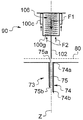
원료 캡슐이 사용자에 의해 머신에 도입되면, 머신은 폐쇄될 수 있다 (도 1 의 위치). 보다 자세하게는, 머신은 도 2 (또한 도 5) 에 도시된 위치에서부터 도 1 (또한 도 7) 위치로 폐쇄 기구 (52) 를 작동시킴으로써 폐쇄된다.Once the raw capsule is introduced into the machine by the user, the machine can be closed (position in FIG. 1). More specifically, the machine is closed by operating the
도 5 의 위치에서 도 7 의 위치로 머신을 작동시키는 중에, 샤프트 (234) 는 그 반대편 정지 단부에 아래로 안내 부재 (236) (예를 들어, 레일 부재 또는 슬롯) 안으로 슬라이딩한다.During operation of the machine from the position of FIG. 5 to the position of FIG. 7, the
이러한 배열체는 지지 수단 (226) 을 유지하는 유지 수단으로서 작용하는 반면, 주입 유닛 (보다 특히, 주입 부재 (202), 지지부 (80) 및 케이싱 (222)) 은 도 7 의 폐쇄 위치에 도달하도록 하방으로 계속 이동한다.This arrangement acts as a retaining means for holding the support means 226, while the injection unit (more particularly, the
따라서, 지지 부재 (226) 가 하방으로 더 이동하는 것이 제한되기 때문에, 이에 연결된 기다란 세척 부재 (232) 는 상부 위치에 유지되어 채널 (210) 로부터 부분적으로 인출된다.Thus, because the
도 7 에 도시된 바와 같이, 부재 (232) 는 제 1 및 제 2 채널부 (210a, 210b) 로부터 인출되어 그 자유 말단이 제 3 채널부 (제 2 휴지 위치) 에 위치된다. 이렇게 함으로써, 상기 위치에서, 액체가 제트 형태로 유출 오리피스 (210a) 를 통하여 나가기 전에 덕트 (222f, 222g) 중 하나, 내부 공동 (224), 관통 홀 (222d) 및 내부 채널부 (210c, 210b, 210a) 를 통하여 연속적으로 도입되도록 할 수 있다. 제트는 원료 캡슐안으로 주입된다.As shown in FIG. 7, the
도 6 에 도시된 주입 유닛의 내부 형상 덕분에, 내부 관통 채널 (210) 로부터 부분적으로 기다란 세척 부재 (232) 만을 인출할 수 있다.Thanks to the internal shape of the injection unit shown in FIG. 6, only a partially elongated cleaning
이는, 부재 (232) 및 지지 부재 (226) 에 의해 이동될 경로가 채널로부터 부재 (232) 를 완전히 제거할 필요성과 비교하여 줄어든 길이로 되기 때문에 유리하다.This is advantageous because the path to be moved by the
따라서, 안내 수단 (236) 내에서 샤프트 (234) 에 의해 이동되는 경로에 대응하는 이러한 줄어든 경로는, 그의 외부 크기를 변형시키지 않으면서, 머신내에 용이하게 수용될 수 있다.Thus, this reduced path corresponding to the path traveled by the
따라서 도 5 의 위치에서 도 7 의 위치로 또한 그 반대로 머신을 작동시키면, 기다란 세척 부재 (232) 는 채널 (210) 내에서, 특히 폐기물, 스케일링 퇴적물 등의 퇴적물에 의해 가장 막히기 쉬운 제 1 채널부 (210a) 내에서 슬라이딩한다.Thus, when the machine is operated from the position of FIG. 5 to the position of FIG. 7 and vice versa, the
슬라이딩 운동은, 채널부를 한정하는 벽의 내부면에 축적될 수 있는 어떠한 퇴적물의 제거를 가능하게 한다.The sliding movement allows the removal of any deposits that may accumulate on the inner surface of the wall defining the channel portion.
머신은 도 7 의 위치에서 도 5 의 위치로 개방되도록 작동되면, 지지 부재 및 기다란 세척 부재의 주입 유닛에 대한 역운동이 발생한다. 그 후, 기다란 세척 부재는, 액체가 상기 채널부내에서 순환된 후, 세척할 제 2 및 제 1 채널부에 도입된다. 이러한 세척 장치 및 관련 기구는 특히 신뢰가능함을 알아야 한다. 게다가, 캡슐을 도입하고 또한 이 캡슐을 제거하기 위해서 머신은 2 번 개방되기 때문에, 머신의 사용 사이클마다 2 번 세척을 실시한다.When the machine is operated to open from the position of FIG. 7 to the position of FIG. 5, reverse motion occurs with respect to the injection unit of the support member and the elongate cleaning member. Thereafter, the elongate washing member is introduced into the second and first channel portions to be cleaned after the liquid is circulated in the channel portions. It should be appreciated that such cleaning devices and associated instruments are particularly reliable. In addition, since the machine is opened twice to introduce the capsule and to remove it, two washes are performed for each use cycle of the machine.
원료 캡슐 (54) 은, 음료 또는 더 넓은 범위에서 액체 식용물을 제조하기 위해 액체, 예를 들어 물을 추가함으로써 사용되는 식품 원료 또는 물질을 포함함을 알아야 한다.It should be noted that the
이러한 원료는 커피, 예를 들어 로스트 및 분쇄된 커피일 수 있다.Such raw materials may be coffee, for example roast and ground coffee.
다른 원료는, 비한정적인 방식으로, 차 (잎차, 허브차 또는 과일차), 용해성 차 또는 용해성 커피, 분쇄된 커피 및 용해성 커피의 혼합물, 코코아, 또는 코코아 또는 초콜릿류 또는 커피를 포함하는 보충 제품, 수프, 또는 예를 들어 우려낸 형태의 식품들을 포함한다.Other ingredients include, but are not limited to, tea (leaf tea, herbal tea or fruit tea), soluble tea or soluble coffee, a mixture of ground coffee and soluble coffee, cocoa, or supplement products including cocoa or chocolates or coffee. , Soups, or foods, for example, in boiled form.
어떠한 원료 캡슐이 사용될 수 있고, 예를 들어 필터 팟 (filter pods) 등의 개방 캡슐이 사용될 수 있음을 알아야 한다.It should be appreciated that any raw capsule may be used, for example open capsules such as filter pods.
변형예로서, 덕트 등의 수단에 의해 연결될 수 있는 1 개 초과의 니들 요소를 구비한 주입 부재를 구성할 수 있다.As a variant, it is possible to construct an injection member with more than one needle element that can be connected by means such as a duct.
이러한 니들 요소의 패턴 및 형상은 제조할 음료의 주입 조건에 대한 상이한 요건을 만족시키도록 변할 수 있다. 특히, 주입 조건은 특히 원료 캡슐 (54) 내에 제공된 물질의 용해 및/또는 추출에 있어서 변할 수 있다.The pattern and shape of these needle elements can be varied to meet different requirements for the pouring conditions of the beverage to be produced. In particular, the injection conditions may vary, particularly in dissolution and / or extraction of the material provided in the
본원에 기재된 본원의 바람직한 실시형태에 대한 다양한 변경 및 수정이 당업자에게 명백함을 이해해야 한다. 이러한 변경 및 수정은 본 발명의 사상 및 관점을 벗어나지 않고 또한 이에 수반되는 장점을 감소시키지 않으면서 실시될 수 있다. 따라서, 이러한 변경 및 수정은 첨부된 청구범위에 의해 포함되는 것으로 의도된다.It should be understood that various changes and modifications to the preferred embodiments herein described herein will be apparent to those skilled in the art. Such changes and modifications can be made without departing from the spirit and aspects of the invention and without diminishing its accompanying advantages. Accordingly, such changes and modifications are intended to be included by the appended claims.
Claims (18)
상기 음료 제조 시스템은 원료 캡슐 (54) 및 음료 제조 머신 (2; 200) 을 포함하고,
상기 음료 제조 머신은,
- 액체를 상기 원료 캡슐에 주입하는 적어도 하나의 내부 관통 채널 (75; 210) 을 구비한 주입 유닛 (73; 204),
- 상기 음료 제조 머신이 음료를 제조하도록 하는 조작 수단 (operating means) 을 구비하는, 상기 음료 제조 시스템에 있어서,
상기 음료 제조 머신은 적어도 하나의 상기 내부 관통 채널을 자동 세척하는 세척 장치 (90; 220) 를 더 포함하고, 상기 세척 장치는 상기 조작 수단에 의해 작동되는 것을 특징으로 하는, 음료 제조 시스템.As a beverage production system (1) for producing a beverage by injecting a liquid into a raw capsule,
The beverage preparation system comprises a raw capsule 54 and a beverage preparation machine 2; 200,
The beverage production machine,
An injection unit 73; 204 with at least one inner through channel 75; 210 for injecting liquid into the raw capsule,
-Said beverage preparation system comprising operating means for causing said beverage preparation machine to produce a beverage,
The beverage production machine further comprises a cleaning device (90; 220) for automatically cleaning at least one of the inner through channels, wherein the cleaning device is operated by the operating means.
상기 세척 장치 (90; 220) 는 기다란 세척 부재 (102; 232) 를 구비하고, 상기 세척 장치의 작동으로 상기 기다란 세척 부재를 적어도 하나의 상기 내부 관통 채널 내에서 슬라이딩시키는 것을 특징으로 하는, 음료 제조 시스템.The method of claim 1,
The cleaning device (90; 220) has an elongate cleaning member (102; 232), characterized in that the operation of the cleaning device slides the long cleaning member in at least one of the inner through channels. system.
상기 기다란 세척 부재 (102; 232) 는, 상기 기다란 세척 부재가 적어도 하나의 상기 내부 관통 채널 (75; 210) 내에서 자유 돌출 단부까지 연장하는 제 1 작동 위치와, 상기 기다란 세척 부재가 적어도 하나의 상기 내부 관통 채널로부터 적어도 부분적으로 인출되는 제 2 휴지 위치 (rest position) 의 2 개의 위치들을 자동적으로 점유할 수 있는 것을 특징으로 하는, 음료 제조 시스템.3. The method of claim 2,
The elongate cleaning member (102; 232) has a first operating position in which the elongated cleaning member extends to at least one freely projecting end in the at least one inner through channel (75; 210) and the elongated cleaning member is at least one. And can automatically occupy two positions of a second rest position that is at least partially withdrawn from the inner through channel.
적어도 하나의 상기 내부 관통 채널 (210) 은, 적어도 하나의 상기 내부 관통 채널의 자유 돌출 단부 (210d) 를 포함하고 또한 제 1 내경 (d1) 을 가지는 제 1 채널부 (210a) 와, 상기 제 1 채널부의 상류측에 배치되고 또한 확장된 제 2 내경 (d2, d3) 을 가지는 적어도 하나의 상류측 채널부 (210b, 210c) 의 적어도 2 개의 채널부를 포함하는 것을 특징으로 하는, 음료 제조 시스템.The method according to claim 2 or 3,
At least one inner through channel 210 includes a first channel portion 210a that includes a free protruding end 210d of at least one inner through channel and has a first inner diameter d1, and the first And at least two channel portions of at least one upstream channel portion (210b, 210c) disposed upstream of the channel portion and having an enlarged second inner diameter (d2, d3).
상기 기다란 세척 부재 (232) 는, 제 2 휴지 위치에서, 적어도 하나의 상류측 채널부에 위치되는 자유 말단 (232a) 을 구비하는 것을 특징으로 하는, 음료 제조 시스템.The method according to claim 3 or 4,
The elongated washing member (232) is characterized in that it has a free end (232a) located in at least one upstream channel portion in a second resting position.
상기 기다란 세척 부재 (232) 는, 상기 기다란 세척 부재가 안으로 슬라이딩할 수 있으면서 제 1 채널부 (210a) 의 제 1 내경에 실질적으로 맞춰지는 외경을 가지는 것을 특징으로 하는, 음료 제조 시스템.The method according to claim 4 or 5,
The elongated cleaning member (232) is characterized in that the elongated cleaning member has an outer diameter that is substantially adapted to the first inner diameter of the first channel portion (210a) while being able to slide in.
상기 조작 수단은, 원료 캡슐을 안으로 도입할 수 있도록 상기 음료 제조 머신을 개방하는 제 1 개방 위치로부터, 상기 음료 제조 머신을 폐쇄하고 액체 주입을 위해 상기 음료 제조 머신 내부에 상기 원료 캡슐을 두는 제 2 폐쇄 위치로 또한 그 반대로 상기 음료 제조 머신을 작동시키는 작동 수단 (actuation means) 을 포함하고, 상기 세척 장치는 상기 작동 수단에 의해 작동되는 것을 특징으로 하는, 음료 제조 시스템.7. The method according to any one of claims 1 to 6,
The operating means may comprise a second from the first open position of opening the beverage production machine to introduce the raw material capsule into the second closing the beverage production machine and placing the raw material capsule inside the beverage production machine for liquid injection. Actuation means for operating said beverage preparation machine in a closed position and vice versa, wherein said cleaning device is operated by said actuation means.
상기 기다란 세척 부재 (232) 및 상기 주입 유닛 (204) 은, 상기 음료 제조 머신이 상기 제 1 개방 위치로부터 상기 제 2 폐쇄 위치로 또한 그 반대로 작동되면 서로에 대하여 이동가능한 것을 특징으로 하는, 음료 제조 시스템.The method according to claim 2 and 7,
The elongate cleaning member 232 and the injection unit 204 are movable relative to each other when the beverage preparation machine is operated from the first open position to the second closed position and vice versa. system.
상기 세척 장치 (220) 는 상기 기다란 세척 부재 (232) 가 연결되는 지지 부재 (226) 를 구비하고, 상기 지지 부재는 줄어든 경로에 걸쳐서 주입 유닛 (204) 에 대하여 이동가능하여, 상기 기다란 세척 부재는 이의 상기 제 2 휴지 위치에서 적어도 하나의 상기 내부 관통 채널 (210) 로부터 부분적으로만 인출되는 것을 특징으로 하는, 음료 제조 시스템.The method according to claim 3 and 8,
The cleaning device 220 has a support member 226 to which the elongate cleaning member 232 is connected, the support member being movable relative to the injection unit 204 over a reduced path such that the elongated cleaning member is And only partially withdrawn from the at least one inner through channel (210) in its second resting position.
상기 지지 부재 (226) 는, 상기 기다란 세척 부재에 연결되는 일방의 단부 (226a) 와 상기 음료 제조 머신에 연결되는 안내 수단 (236) 과 연결되는 반대편 타방의 단부 (226b) 의 2 개의 반대편 단부들을 구비하고,
상기 반대편 타방의 단부는, 상기 음료 제조 머신이 상기 제 1 개방 위치로부터 상기 제 2 폐쇄 위치로 또한 그 반대로 작동되면 상기 줄어든 경로에 걸쳐서 슬라이딩가능하게 안내되는 것을 특징으로 하는, 음료 제조 시스템.The method of claim 9,
The support member 226 has two opposite ends of one end 226a connected to the elongated washing member and the opposite other end 226b connected to the guide means 236 connected to the beverage making machine. Equipped,
The opposite other end is slidably guided over the reduced path when the beverage making machine is operated from the first open position to the second closed position and vice versa.
상기 음료 제조 머신 (2) 은,
- 액체 공급원 (10),
- 상기 액체 공급원으로부터의 액체를 주입 유닛 (73) 쪽으로 펌핑하는 펌프 (20),
- 상기 액체가 상기 액체 공급원으로부터 상기 주입 유닛 쪽으로 펌핑되도록 하는 활성화 수단 (activation means) 을 구비하고,
상기 세척 장치 (90) 는 상기 활성화 수단에 의해 작동되는 것을 특징으로 하는, 음료 제조 시스템.11. The method according to any one of claims 1 to 10,
The beverage production machine 2,
-Liquid source (10),
A pump 20 pumping liquid from the liquid source towards the injection unit 73,
Activation means for causing the liquid to be pumped from the liquid source towards the injection unit,
Wherein said washing device (90) is operated by said activating means.
상기 기다란 세척 부재 (102) 는 적어도 하나의 상기 내부 관통 채널안으로의 액체의 주입 또는 비주입에 따라서 상기 2 개의 위치를 자동적으로 점유할 수 있고,
상기 기다란 세척 부재는 내부로의 액체 주입이 없을 시에 상기 제 1 작동 위치에 있으며,
상기 기다란 세척 부재는 적어도 하나의 상기 내부 관통 채널안으로 주입된 액체의 압력으로 인해 제 2 작동 위치에 있는 것을 특징으로 하는, 음료 제조 시스템.The method according to claim 3 or 11,
The elongate cleaning member 102 can automatically occupy the two positions upon injection or non-infusion of liquid into at least one of the inner through channels,
The elongate cleaning member is in the first operating position in the absence of liquid injection therein,
And the elongate cleaning member is in a second operating position due to the pressure of the liquid injected into the at least one inner through channel.
상기 세척 장치 (90) 는, 상기 기다란 세척 부재가 상기 제 1 작동 위치를 점유하는 관점에서 적어도 하나의 상기 내부 관통 채널안으로 삽입되도록 가압하도록 제 1 미리 정해진 힘 (F1) 을 상기 기다란 세척 부재에 가하는 작동 수단 (active means; 106) 을 포함하고,
상기 기다란 세척 부재 (102) 는, 상기 제 1 미리 정해진 힘에 대향하고 또한 적어도 하나의 상기 내부 관통 채널안으로 주입될 액체의 압력 작용으로 후방으로 밀려질 수 있어서, 상기 기다란 세척 부재는 적어도 하나의 상기 내부 관통 채널로부터 적어도 부분적으로 인출되는 것을 특징으로 하는, 음료 제조 시스템.13. The method of claim 12,
The cleaning device 90 applies a first predetermined force F1 to the elongate cleaning member to press the elongate cleaning member to be inserted into at least one of the inner through channels in terms of occupying the first operating position. Active means 106,
The elongate cleaning member 102 can be pushed back against the first predetermined force and also under the action of the pressure of the liquid to be injected into the at least one inner through channel such that the elongate cleaning member is at least one of the A beverage production system, characterized in that it is at least partly withdrawn from the inner through channel.
상기 음료 제조 머신 (2) 은 상기 원료 캡슐을 유지하기 위한 캡슐 홀더 (58) 를 포함하는 것을 특징으로 하는, 음료 제조 시스템.14. The method according to any one of claims 1 to 13,
The beverage production machine (2) is characterized in that it comprises a capsule holder (58) for holding the raw capsule.
상기 세척 장치는,
- 지지 부재 (100; 226), 및
- 상기 지지 부재에 연결되고 또한 상기 지지 부재를 세척하기 위해 상기 채널안으로 삽입되는데 적합한 기다란 세척 부재 (102; 232) 를 포함하고,
상기 지지 부재와 상기 기다란 세척 부재는, 상기 기다란 세척 부재가 채널 (75; 210) 내에서 그의 자유 돌출 단부까지 연장하는 제 1 작동 위치를 점유하도록 가압하기 위해서 미리 정해진 힘을 작용시켜 전방으로 이동가능하고,
상기 지지 부재와 상기 기다란 세척 부재는, 상기 기다란 세척 부재가 상기 채널로부터 적어도 부분적으로 인출되는 제 2 휴지 위치를 점유하도록 가압하기 위해서 대향하는 미리 정해진 힘을 작용시킨 상태에서 후방으로 이동가능한, 조립체.An assembly comprising a channel (75; 210) in which liquid flows temporarily and a cleaning device for cleaning the channel, wherein
The washing device,
Support members 100 and 226, and
An elongate cleaning member (102; 232) connected to said support member and suitable for insertion into said channel for cleaning said support member,
The support member and the elongate cleaning member are movable forward by applying a predetermined force to force the elongate cleaning member to occupy a first operating position extending in its channel 75 (210) to its free protruding end. and,
And the support member and the elongate cleaning member are movable backwards with an opposing predetermined force applied to force the elongate cleaning member to occupy a second rest position at least partially withdrawn from the channel.
상기 음료 제조 머신은 상기 원료 캡슐안으로 액체를 주입하기 위해 적어도 하나의 내부 관통 채널 (75; 210) 을 갖춘 주입 유닛 (73; 204) 을 포함하고,
상기 방법은,
- 원료 캡슐 (54) 을 제공하는 단계, 및
- 상기 음료 제조 머신이 음료를 제조하도록 상기 음료 제조 머신을 조작하는 조작 단계를 포함하고,
상기 방법은, 적어도 하나의 상기 내부 관통 채널을 세척하는 단계를 더 포함하고,
상기 세척하는 단계는 상기 음료 제조 머신을 조작하는 조작 단계가 실시되면 자동적으로 개시되는 것을 특징으로 하는, 음료를 제조하는 방법.A method of producing a beverage by a beverage preparation machine (2; 200) by injecting a liquid into a raw material capsule,
The beverage preparation machine comprises an infusion unit 73; 204 with at least one internal through channel 75; 210 for injecting liquid into the raw capsule;
The method comprises:
Providing a raw capsule 54, and
An operating step of operating the beverage preparation machine such that the beverage preparation machine produces a beverage,
The method further comprises washing at least one of the inner through channel,
Said washing step is initiated automatically when an operating step of operating said beverage preparation machine is carried out.
상기 음료 제조 머신을 조작하는 조작 단계는,
상기 원료 캡슐을 안으로 도입할 수 있도록 상기 음료 제조 머신을 개방하는 제 1 개방 위치로부터, 상기 음료 제조 머신을 폐쇄하고 액체 주입을 위해 상기 음료 제조 머신 내부에 상기 원료 캡슐을 두는 제 2 폐쇄 위치로 또한 그 반대로 상기 음료 제조 머신을 작동시키는 작동 단계를 포함하는 것을 특징으로 하는, 음료를 제조하는 방법.17. The method of claim 16,
The operation step of operating the beverage production machine,
From a first open position of opening the beverage preparation machine to allow introduction of the raw capsule into the second closed position of closing the beverage preparation machine and placing the raw capsule inside the beverage preparation machine for liquid injection; And vice versa, an operating step of operating said beverage preparation machine.
상기 음료 제조 머신은 액체 공급원 (10) 및 펌프 (20) 를 포함하고,
상기 음료를 제조하는 방법은 적어도 하나의 상기 내부 관통 채널을 통하여 상기 원료 캡슐 안으로 액체를 주입하는 단계를 더 포함하고,
자동적으로 개시되는 상기 세척하는 단계는 액체의 주입 전에, 및/또는 액체의 주입 중에, 및/또는 액체의 주입 후에 실시되는 것을 특징으로 하는, 음료를 제조하는 방법.18. The method according to claim 16 or 17,
The beverage preparation machine includes a liquid source 10 and a pump 20,
The method of preparing the beverage further comprises injecting a liquid into the raw capsule through at least one inner through channel,
Wherein the automatically initiated washing step is carried out before the injection of the liquid and / or during the injection of the liquid and / or after the injection of the liquid.
Applications Claiming Priority (3)
| Application Number | Priority Date | Filing Date | Title |
|---|---|---|---|
| EP10193797.7 | 2010-12-06 | ||
| EP10193797A EP2460449A1 (en) | 2010-12-06 | 2010-12-06 | A beverage preparation machine with automatic cleaning system |
| PCT/EP2011/071783 WO2012076483A2 (en) | 2010-12-06 | 2011-12-05 | A beverage preparation machine with automatic cleaning system |
Publications (1)
| Publication Number | Publication Date |
|---|---|
| KR20130105693A true KR20130105693A (en) | 2013-09-25 |
Family
ID=43901369
Family Applications (1)
| Application Number | Title | Priority Date | Filing Date |
|---|---|---|---|
| KR1020137017609A KR20130105693A (en) | 2010-12-06 | 2011-12-05 | A beverage preparation machine with automatic cleaning system |
Country Status (17)
| Country | Link |
|---|---|
| US (1) | US9456716B2 (en) |
| EP (2) | EP2460449A1 (en) |
| JP (1) | JP2013544602A (en) |
| KR (1) | KR20130105693A (en) |
| CN (1) | CN103249337B (en) |
| AR (1) | AR085000A1 (en) |
| AU (1) | AU2011340646A1 (en) |
| BR (1) | BR112013013772A2 (en) |
| CA (1) | CA2817454A1 (en) |
| CL (1) | CL2013001614A1 (en) |
| ES (1) | ES2745134T3 (en) |
| IL (1) | IL226211A0 (en) |
| MX (1) | MX2013006350A (en) |
| RU (1) | RU2013131079A (en) |
| SG (1) | SG190178A1 (en) |
| WO (1) | WO2012076483A2 (en) |
| ZA (1) | ZA201305073B (en) |
Families Citing this family (22)
| Publication number | Priority date | Publication date | Assignee | Title |
|---|---|---|---|---|
| CN202714727U (en) * | 2012-06-18 | 2013-02-06 | 漳州灿坤实业有限公司 | Device for quickly loading and unloading extracted material packages |
| US9375114B2 (en) | 2013-05-22 | 2016-06-28 | Sunbeam Products, Inc. | Hot beverage maker with cleaning apparatus and related method |
| US10285536B2 (en) | 2013-07-17 | 2019-05-14 | Nestec S.A. | Food or beverage preparation machine with antiscaling pipe system |
| US10806295B2 (en) | 2013-10-22 | 2020-10-20 | Koninklijke Philips N.V. | Descaling hot-beverage producing machines |
| US20150129003A1 (en) * | 2013-11-13 | 2015-05-14 | Uni-Splendor Corp. | Coffee Brewer Nozzle Cleaning Device |
| CA2958958A1 (en) * | 2014-10-08 | 2016-04-14 | Nestec S.A. | Reconfigurable beverage preparation machine |
| USD766654S1 (en) * | 2015-02-10 | 2016-09-20 | Sunbeam Products, Inc. | Beverage maker cleaning device |
| ITUB20154199A1 (en) | 2015-10-07 | 2017-04-07 | Carpigiani Group Ali Spa | MACHINE AND METHOD FOR THE REALIZATION OF LIQUID AND SEMILIQUID PRODUCTS OF THE HOT OR COLD TYPE. |
| US20170252996A1 (en) * | 2016-03-03 | 2017-09-07 | Juicero, Inc. | Juicer cartridge with secondary flow channel |
| US20170251709A1 (en) * | 2016-03-04 | 2017-09-07 | Food & Beverage Innovations, Llc | Device for preparation of gelatin-based products |
| IT201600074471A1 (en) | 2016-07-15 | 2018-01-15 | Ali Group Srl Carpigiani | MACHINE AND METHOD FOR THE PRODUCTION OF LIQUID AND SEMIQUID PRODUCTS OF THE ICE CREAM, PASTRY OR RESTAURANT SECTOR. |
| IT201600100869A1 (en) * | 2016-10-07 | 2018-04-07 | Ali Group Srl Carpigiani | METHOD AND CLEANING SYSTEM OF A MACHINE FOR THE REALIZATION OF LIQUID AND / OR SEMIQUINE FOODSTUFFS IN THE ICE-CREAM, PASTRY OR RESTAURANT SECTOR |
| WO2018089460A1 (en) | 2016-11-09 | 2018-05-17 | Pepsico, Inc. | Carbonated beverage makers, methods, and systems |
| CN109008640A (en) * | 2017-04-08 | 2018-12-18 | 聂世林 | Quickly prepare the container of beverage |
| CN109512282A (en) * | 2017-04-08 | 2019-03-26 | 沈娟 | A method of preparing beverage |
| IT201700043975A1 (en) | 2017-04-21 | 2018-10-21 | Ali Group Srl Carpigiani | MACHINE AND METHOD FOR THE PRODUCTION OF LIQUID AND SEMIQUID PRODUCTS OF THE ICE CREAM SECTOR. |
| IT201700060299A1 (en) * | 2017-06-01 | 2018-12-01 | Bruno Bardazzi | Infusion unit for beverage preparation machines |
| CN108433549A (en) * | 2018-02-26 | 2018-08-24 | 无锡鼎加弘思饮品科技有限公司 | Capsule beverage machine accommodating chamber flushing machine and its operating method |
| EP3871568A1 (en) * | 2018-10-23 | 2021-09-01 | Novadelta-Comércio e Industria de Cafés, S.A. | Systems of distribution of edible products with improved access arrangements and geometries |
| CN109730539B (en) * | 2019-01-23 | 2023-09-12 | 宁波美侬咖啡机有限公司 | Self-cleaning puncture needle device |
| BR112022009586A2 (en) * | 2019-12-04 | 2022-08-02 | Nestle Sa | CLEANING APPLIANCE FOR A BEVERAGE PREPARING MACHINE |
| JP7252631B2 (en) * | 2020-01-21 | 2023-04-05 | 株式会社大都技研 | Beverage production apparatus and method |
Family Cites Families (18)
| Publication number | Priority date | Publication date | Assignee | Title |
|---|---|---|---|---|
| US2018086A (en) * | 1934-04-26 | 1935-10-22 | John L Parsons | Bottle cleaning device |
| US3599557A (en) * | 1970-05-19 | 1971-08-17 | Virgilio Leal | Coffee-brewing assembly for espresso coffeemaking device |
| CH605293A5 (en) | 1976-12-17 | 1978-09-29 | Nestle Sa | |
| CH668544A5 (en) | 1986-04-24 | 1989-01-13 | Nestle Sa | CARTRIDGE COFFEE EXTRACTION DEVICE. |
| CN2107305U (en) * | 1991-12-21 | 1992-06-17 | 谭灿辉 | Microhole filtering pipe with washing device |
| JPH07171825A (en) * | 1993-09-21 | 1995-07-11 | Toho Kikai Kogyo Kk | Mixing head |
| CH689753A5 (en) | 1995-02-08 | 1999-10-15 | Lough J Ltd | Process for the preparation of a coffee-type beverage expressed and device for its implementation. |
| DE19522025A1 (en) * | 1995-06-17 | 1996-12-19 | Braun Ag | Hot drink preparation machine, especially coffee or and expresso coffee maker |
| ES2407963T3 (en) | 2002-01-16 | 2013-06-17 | Societe Des Produits Nestle S.A. | Closed capsule with a cup that has opening means |
| US6889603B2 (en) * | 2002-12-24 | 2005-05-10 | Nestec S.A. | Clean-in-place automated food or beverage dispenser |
| CA2579475C (en) | 2004-08-23 | 2009-10-20 | Nestec S.A. | Capsule for preparing and delivering a drink by injecting a pressurized fluid into the capsule |
| US8889207B2 (en) * | 2007-02-01 | 2014-11-18 | Bsh Bosch Und Siemens Hausgeraete Gmbh | Steam function at the end of a brewing process |
| PL1967100T3 (en) | 2007-03-06 | 2009-11-30 | Nestec Sa | System for preparing a beverage from a capsule and method |
| US8468934B2 (en) * | 2007-08-29 | 2013-06-25 | Nestec S.A. | Dispensing device for preparing and dispensing food and/or nutritional composition |
| SI2071986T1 (en) * | 2007-12-18 | 2012-04-30 | Nestec Sa | System for preparing a beverage from ingredients supported by an encoded insert |
| ES2359997T3 (en) | 2007-12-18 | 2011-05-30 | Nestec S.A. | DEVICE FOR PREPARING A DRINK WITH A REMOVABLE INJECTION ELEMENT. |
| ITFI20080198A1 (en) * | 2008-10-15 | 2010-04-16 | Saeco Ipr Ltd | "COFFEE MACHINE'" |
| GB2475621B (en) * | 2009-11-20 | 2012-10-24 | Ali Waqar Majeed | Cleaning apparatus |
-
2010
- 2010-12-06 EP EP10193797A patent/EP2460449A1/en not_active Withdrawn
-
2011
- 2011-12-05 CN CN201180058777.8A patent/CN103249337B/en not_active Expired - Fee Related
- 2011-12-05 KR KR1020137017609A patent/KR20130105693A/en active IP Right Grant
- 2011-12-05 BR BR112013013772A patent/BR112013013772A2/en not_active IP Right Cessation
- 2011-12-05 AU AU2011340646A patent/AU2011340646A1/en not_active Abandoned
- 2011-12-05 SG SG2013034780A patent/SG190178A1/en unknown
- 2011-12-05 JP JP2013541383A patent/JP2013544602A/en active Pending
- 2011-12-05 RU RU2013131079/12A patent/RU2013131079A/en not_active Application Discontinuation
- 2011-12-05 US US13/991,800 patent/US9456716B2/en active Active
- 2011-12-05 CA CA2817454A patent/CA2817454A1/en not_active Abandoned
- 2011-12-05 ES ES11793755T patent/ES2745134T3/en active Active
- 2011-12-05 MX MX2013006350A patent/MX2013006350A/en not_active Application Discontinuation
- 2011-12-05 WO PCT/EP2011/071783 patent/WO2012076483A2/en active Application Filing
- 2011-12-05 EP EP11793755.7A patent/EP2648581B8/en not_active Not-in-force
- 2011-12-06 AR ARP110104570A patent/AR085000A1/en unknown
-
2013
- 2013-05-07 IL IL226211A patent/IL226211A0/en unknown
- 2013-06-06 CL CL2013001614A patent/CL2013001614A1/en unknown
- 2013-07-05 ZA ZA2013/05073A patent/ZA201305073B/en unknown
Also Published As
| Publication number | Publication date |
|---|---|
| SG190178A1 (en) | 2013-06-28 |
| EP2648581B8 (en) | 2019-08-07 |
| CL2013001614A1 (en) | 2013-09-23 |
| WO2012076483A2 (en) | 2012-06-14 |
| IL226211A0 (en) | 2013-07-31 |
| AR085000A1 (en) | 2013-07-24 |
| US20130287914A1 (en) | 2013-10-31 |
| US9456716B2 (en) | 2016-10-04 |
| ES2745134T3 (en) | 2020-02-27 |
| EP2648581B1 (en) | 2019-06-26 |
| CN103249337A (en) | 2013-08-14 |
| WO2012076483A3 (en) | 2012-09-13 |
| MX2013006350A (en) | 2013-08-26 |
| EP2460449A1 (en) | 2012-06-06 |
| CA2817454A1 (en) | 2012-06-14 |
| AU2011340646A1 (en) | 2013-05-30 |
| BR112013013772A2 (en) | 2016-09-13 |
| ZA201305073B (en) | 2014-12-23 |
| RU2013131079A (en) | 2015-01-20 |
| CN103249337B (en) | 2017-06-09 |
| EP2648581A2 (en) | 2013-10-16 |
| JP2013544602A (en) | 2013-12-19 |
Similar Documents
| Publication | Publication Date | Title |
|---|---|---|
| KR20130105693A (en) | A beverage preparation machine with automatic cleaning system | |
| AU2008306060C1 (en) | Beverage brewing unit | |
| JP5600738B2 (en) | Infusion unit for making beverages from single-use sachets and apparatus having the unit | |
| CA2834256C (en) | Delivery assembly for machines for preparing liquid products via cartridges | |
| KR20100113447A (en) | Infusion device to prepare beverages from single-serving capsules with capsule centering device | |
| KR20140138959A (en) | A beverage preparation machine with cleanable brewing head | |
| AU2012101844A4 (en) | Combination beverage brewing unit and capsule |
Legal Events
| Date | Code | Title | Description |
|---|---|---|---|
| A201 | Request for examination | ||
| E902 | Notification of reason for refusal | ||
| E701 | Decision to grant or registration of patent right |