JP2013529570A - Reduced resistance to ship hulls - Google Patents
Reduced resistance to ship hulls Download PDFInfo
- Publication number
- JP2013529570A JP2013529570A JP2013515893A JP2013515893A JP2013529570A JP 2013529570 A JP2013529570 A JP 2013529570A JP 2013515893 A JP2013515893 A JP 2013515893A JP 2013515893 A JP2013515893 A JP 2013515893A JP 2013529570 A JP2013529570 A JP 2013529570A
- Authority
- JP
- Japan
- Prior art keywords
- control
- path
- fluid
- flow
- microfluidic
- Prior art date
- Legal status (The legal status is an assumption and is not a legal conclusion. Google has not performed a legal analysis and makes no representation as to the accuracy of the status listed.)
- Pending
Links
Images


Classifications
-
- B—PERFORMING OPERATIONS; TRANSPORTING
- B63—SHIPS OR OTHER WATERBORNE VESSELS; RELATED EQUIPMENT
- B63B—SHIPS OR OTHER WATERBORNE VESSELS; EQUIPMENT FOR SHIPPING
- B63B1/00—Hydrodynamic or hydrostatic features of hulls or of hydrofoils
- B63B1/32—Other means for varying the inherent hydrodynamic characteristics of hulls
- B63B1/34—Other means for varying the inherent hydrodynamic characteristics of hulls by reducing surface friction
- B63B1/38—Other means for varying the inherent hydrodynamic characteristics of hulls by reducing surface friction using air bubbles or air layers gas filled volumes
-
- B—PERFORMING OPERATIONS; TRANSPORTING
- B01—PHYSICAL OR CHEMICAL PROCESSES OR APPARATUS IN GENERAL
- B01F—MIXING, e.g. DISSOLVING, EMULSIFYING OR DISPERSING
- B01F23/00—Mixing according to the phases to be mixed, e.g. dispersing or emulsifying
- B01F23/20—Mixing gases with liquids
-
- B—PERFORMING OPERATIONS; TRANSPORTING
- B63—SHIPS OR OTHER WATERBORNE VESSELS; RELATED EQUIPMENT
- B63B—SHIPS OR OTHER WATERBORNE VESSELS; EQUIPMENT FOR SHIPPING
- B63B1/00—Hydrodynamic or hydrostatic features of hulls or of hydrofoils
- B63B1/32—Other means for varying the inherent hydrodynamic characteristics of hulls
- B63B1/34—Other means for varying the inherent hydrodynamic characteristics of hulls by reducing surface friction
- B63B1/38—Other means for varying the inherent hydrodynamic characteristics of hulls by reducing surface friction using air bubbles or air layers gas filled volumes
- B63B2001/387—Other means for varying the inherent hydrodynamic characteristics of hulls by reducing surface friction using air bubbles or air layers gas filled volumes using means for producing a film of air or air bubbles over at least a significant portion of the hull surface
-
- Y—GENERAL TAGGING OF NEW TECHNOLOGICAL DEVELOPMENTS; GENERAL TAGGING OF CROSS-SECTIONAL TECHNOLOGIES SPANNING OVER SEVERAL SECTIONS OF THE IPC; TECHNICAL SUBJECTS COVERED BY FORMER USPC CROSS-REFERENCE ART COLLECTIONS [XRACs] AND DIGESTS
- Y02—TECHNOLOGIES OR APPLICATIONS FOR MITIGATION OR ADAPTATION AGAINST CLIMATE CHANGE
- Y02T—CLIMATE CHANGE MITIGATION TECHNOLOGIES RELATED TO TRANSPORTATION
- Y02T70/00—Maritime or waterways transport
- Y02T70/10—Measures concerning design or construction of watercraft hulls
Abstract
船のハルに対する抵抗を低減させるための泡を発生させるための機構を開示する。泡発生装置は、ハルの外面に取付け可能であり、機構は、発生させた泡の泡サイズを制御するための1つ以上のマイクロ流体装置を含む。 Disclosed is a mechanism for generating bubbles to reduce ship hull resistance. The foam generator can be attached to the outer surface of the hull, and the mechanism includes one or more microfluidic devices for controlling the foam size of the generated foam.
Description
発明の分野
この発明は、概して、船のハルの抵抗を低減させるための泡、特に微泡、の発生に関する。
FIELD OF THE INVENTION This invention relates generally to the generation of bubbles, particularly microbubbles, to reduce ship hull resistance.
発明の背景
船のハルの摩擦抵抗(抵抗とも称される)を低減させることが一般に望ましい。というのも、これにより、船の運行速度の上昇および/または燃料消費の低減をもたらし得るからである。
Background of the Invention It is generally desirable to reduce the frictional resistance (also referred to as resistance) of a ship's hull. This can result in increased ship operating speed and / or reduced fuel consumption.
JP10119875Aは、船本体の球形船首の表面に設置されたチャンバ上に排出ノズルを形成することによって、かつ、空気圧供給手段によってチャンバに供給される空気圧を排出ノズルから噴出させて、泡および空気層が浸水面と接触したままの状態で境界層上で干渉されるようにすることによって、船に対する摩擦抵抗を下げるためのシステムを開示する。排出ノズルはチャンバの前板によって形成され、当該前板はいくつかの孔を有する。空気圧は上記いくつかの孔から水中に噴射されて、これにより、複数個の泡を、これら泡が流線に沿って分散されて浸水面を覆うような態様で排出ノズルの外側で発生させるようする。これにより摩擦を低下させる。 JP10119875A is a method in which a discharge nozzle is formed on a chamber installed on the surface of a spherical bow of a ship body, and air pressure supplied to the chamber is ejected from the discharge nozzle by air pressure supply means, so that bubbles and air layers are generated. Disclosed is a system for reducing frictional resistance to a ship by allowing interference on a boundary layer while still in contact with a flooded surface. The discharge nozzle is formed by a front plate of the chamber, which has several holes. Air pressure is injected into the water from the several holes, thereby generating a plurality of bubbles outside the discharge nozzle in such a manner that the bubbles are distributed along the streamline and cover the flooded surface. To do. This reduces friction.
GB2429435Aは、空気潤滑装置を有する船舶のハルを開示する。空気潤滑装置は、ハルおよび竜骨の外側に取付けられた多孔質膜に加圧空気を供給するための空気ポンプ、または、船舶の竜骨およびハルに取付けられるかもしくは船舶のハル内に装着される空気ダクトのシステムを含む。 GB2429435A discloses a ship hull with an air lubrication device. The air lubrication device is an air pump for supplying pressurized air to the porous membrane attached to the outside of the hull and keel, or air attached to or installed in the keel and hull of the ship. Includes a duct system.
JP10175587Aは、ハルの摩擦抵抗の発生を減らすために小さな気泡が境界層に供給される方法を開示する。泡は、いくつかの小さな出入り口が所与のピッチで形成されている多孔板から吹出される。 JP10175587A discloses a method in which small bubbles are supplied to the boundary layer to reduce the occurrence of hull frictional resistance. Bubbles are blown out of a perforated plate in which several small doorways are formed at a given pitch.
CN2652812Yは、空洞、接続管路、圧力空気電力機械および多孔質シリコン板を含み、抵抗低減に用いられる微泡発生器を開示する。 CN26552812Y discloses a microbubble generator used for resistance reduction, including cavities, connecting lines, pressure air power machines and porous silicon plates.
しかしながら、上述の先行技術のシステムは、船のハルに据付けることのできる泡発生器による泡の発生を開示しているものの、さまざまな運転条件下、たとえばさまざまな速度、水温、喫水などの条件下で、船のハルの抵抗または摩擦抵抗を効率的に低減させるための微泡を発生させる方法を提供するという課題を残している。 However, although the prior art systems described above disclose the generation of foam by a foam generator that can be installed in a ship's hull, various operating conditions, such as various speed, water temperature, draft conditions, etc. Below, the problem remains to provide a method of generating microbubbles for efficiently reducing the hull resistance or frictional resistance of a ship.
概要
この明細書中において、船のハルの抵抗を低減させるための泡を発生させるための機構を開示する。ここで、泡発生装置はハルの外面に取付け可能であり、当該機構は、発生させた泡のうち特定の泡サイズを有する泡を発生させるためのマイクロ流体装置を含む。泡は、ハルの周囲の水の境界層において、すなわち、ハルと周囲の水との間の界面において、形成される。
SUMMARY In this specification, a mechanism for generating bubbles to reduce ship hull resistance is disclosed. Here, the bubble generating device can be attached to the outer surface of the hull, and the mechanism includes a microfluidic device for generating bubbles having a specific bubble size among the generated bubbles. Bubbles are formed at the boundary layer of water around the hull, ie at the interface between the hull and the surrounding water.
発生させた泡の泡サイズは、マイクロ流体装置によって、たとえば泡形成流体の流れを制御することによって、制御可能であってもよく、これにより、泡サイズが効率的に制御されて、さらには、さまざまな運転条件でも効率的かつ制御可能に抵抗を低減させることが可能となる。 The foam size of the generated foam may be controllable by a microfluidic device, for example by controlling the flow of foam-forming fluid, so that the foam size is efficiently controlled, It is possible to reduce the resistance efficiently and in a controllable manner under various operating conditions.
概して、マイクロ流体装置は、幾何学的に小規模に、典型的にはサブミリメートルのスケールにまで抑制された流体を正確に制御かつ操作することを可能にする。概して、マイクロ流体装置は、横寸法が3mm未満、たとえば1mm未満、たとえば500マイクロメートル未満、たとえば100nm〜500マイクロメートルである少なくとも1本の流体経路を備えた装置を含み得る。微小規模での流体の挙動は、表面張力、エネルギ散逸および流体抵抗などの要因がシステムを特色付けている点で、「マイクロ流体」挙動とは異なり得る。経路径が約100ナノメートルから数100マイクロメートルである小規模の場合、流体の運動量の作用を粘度の作用と比較したものであるレイノルズ数は非常に低くなり得る。これにより、結果として、流体同士が従来通りの意味では混合しない可能性があり、流体間の分子輸送が拡散により行われる可能性がある。 In general, microfluidic devices allow precise control and manipulation of fluids that are constrained to a geometrically small scale, typically to the submillimeter scale. In general, microfluidic devices can include devices with at least one fluid path having a lateral dimension of less than 3 mm, such as less than 1 mm, such as less than 500 micrometers, such as between 100 nm and 500 micrometers. The behavior of fluids at a microscale can differ from “microfluidic” behavior in that factors such as surface tension, energy dissipation and fluid resistance characterize the system. For small scales with path diameters of about 100 nanometers to several hundreds of micrometers, the Reynolds number, which compares the fluid momentum effect to the viscosity effect, can be very low. As a result, the fluids may not be mixed in the conventional sense, and molecular transport between the fluids may be performed by diffusion.
マイクロ流体装置という語は、微細加工された経路を通る連続的な流体の流れを操作するための好適な如何なるマイクロ流体構造をも指す。流体の流れを開始させる場合、外部の圧力源、外部の機械的ポンプ、一体化された機械的マイクロポンプによって、または毛細管力と動電的機構との組合せによって実現されてもよい。 The term microfluidic device refers to any suitable microfluidic structure for manipulating a continuous fluid flow through a microfabricated path. Initiating fluid flow may be accomplished by an external pressure source, an external mechanical pump, an integrated mechanical micropump, or by a combination of capillary forces and electrokinetic mechanisms.
発生させた泡は、微泡、すなわち直径が1mm未満、たとえば200μm未満、たとえば150μm未満、たとえば100μm未満、たとえば50μm未満などの泡であってもよく、これにより、十分な浮力を維持しつつ効率的に抵抗を低減させ得る。発生させる泡のサイズを合わせることにより、抵抗低減を向上させ、さまざまな運転条件に適合させ得る。微泡は、空気などの泡形成流体の流れもしくは供給、または、別の好適な気体もしくは気体の混合物、さらには液体、の流れもしくは供給を制御することによって発生させてもよい。泡形成流体という語は、船のハルを囲む水中に放出される際に泡を形成する液体、気体または気体の混合物、たとえば空気などの如何なる好適な流体をも指すよう意図される。いくつかの実施例においては、当該機構は、複数セットのマイクロ流体装置を含み、各セットのマイクロ流体装置は、それぞれの予め定められた周波数で泡を発生させるよう適合される。当該機構は、泡形成流体の供給流を、上記セットのマイクロ流体装置のうち上記周波数とは異なる1つのセットまたはサブセットに選択的に方向付けるための流れセレクタを含む。 The generated bubbles may be microbubbles, i.e. bubbles with a diameter of less than 1 mm, e.g. less than 200 m, e.g. less than 150 m, e.g. less than 100 m, e.g. Thus, the resistance can be reduced. By matching the size of the foam generated, drag reduction can be improved and adapted to various operating conditions. The microbubbles may be generated by controlling the flow or supply of a foam-forming fluid such as air, or another suitable gas or mixture of gases, or even a liquid. The term foam-forming fluid is intended to refer to any suitable fluid, such as a liquid, gas or mixture of gases, such as air, that forms bubbles when released into the water surrounding the hull of the ship. In some embodiments, the mechanism includes multiple sets of microfluidic devices, each set of microfluidic devices being adapted to generate bubbles at a respective predetermined frequency. The mechanism includes a flow selector for selectively directing a foam-forming fluid feed stream to one set or subset of the set of microfluidic devices different from the frequency.
いくつかの実施例においては、マイクロ流体装置は、時間の経過とともにたとえば周期的に変化する流れである泡形成流体の制御可能な流れを供給することにより、制御可能な泡サイズを有する泡を発生させるよう適合される。たとえば、マイクロ流体装置は周期的に変化する流れを作り出すよう適合され得る。好適なマイクロ流体装置の例には、マイクロ流体発振器、マイクロ流体発振器フリップフロップ、マイクロ流体増幅器、マイクロ流体スイッチ、および/またはそれらの組合せが含まれる。たとえば、発生させた泡のサイズおよび/または周波数は、周期的に変化する流れの周波数、たとえば発生させた泡の発生周波数、を選択および/または制御することによって制御されてもよい。したがって、マイクロ流体装置は、制御可能な流体増幅器および/または制御可能な流体発振器および/または制御可能な流体スイッチを含み得る。 In some embodiments, the microfluidic device generates bubbles having a controllable bubble size by providing a controllable flow of foam-forming fluid, eg, a periodically changing flow over time. Adapted to make. For example, the microfluidic device can be adapted to create a periodically changing flow. Examples of suitable microfluidic devices include microfluidic oscillators, microfluidic oscillator flip-flops, microfluidic amplifiers, microfluidic switches, and / or combinations thereof. For example, the size and / or frequency of the generated foam may be controlled by selecting and / or controlling a periodically changing flow frequency, such as the generated frequency of the generated foam. Thus, the microfluidic device may include a controllable fluid amplifier and / or a controllable fluid oscillator and / or a controllable fluid switch.
発生させた泡の流れの周波数を制御可能にすることはさらなる利点である。というのも、これにより、隣接する泡同士の間隔を制御し、こうして、発生させた泡の合着を減らすかまたはさらには最小限にするように、泡の周波数を選択および/または制御することが可能となるからである。 It is a further advantage to be able to control the frequency of the generated bubble flow. Because it controls the spacing between adjacent bubbles, thus selecting and / or controlling the frequency of the bubbles so as to reduce or even minimize the coalescence of the generated bubbles. This is because it becomes possible.
いくつかの実施例においては、当該機構は既存の船に据付けることができる改装可能な装置である。当該機構は、たとえば、当該機構が取付けられる表面を適切に洗浄しかつ準備することを可能にするために、乾ドックにある船に据付けられてもよい。当該機構は、溶接、エポキシ接着剤などの好適な水中接合技術によって水中でも据付け可能であり得る。 In some embodiments, the mechanism is a retrofitable device that can be installed on an existing ship. The mechanism may be installed on a ship in a dry dock, for example, to allow proper cleaning and preparation of the surface to which the mechanism is attached. The mechanism may be installable in water by suitable underwater bonding techniques such as welding, epoxy adhesives and the like.
概して、機構は、溶接、接着剤、エポキシ樹脂接合、2成分のエポキシ樹脂接合、永久磁石などの磁石など、またはこれらの組合せなどの如何なる好適な取付け手段によってもハルの外面、たとえば船の底部および/または側壁に取付け可能であり得る。 In general, the mechanism is not limited to any suitable attachment means such as welding, adhesive, epoxy resin bonding, two-component epoxy resin bonding, magnets such as permanent magnets, or combinations thereof, such as the outer surface of the hull, such as the bottom of the ship and / Or may be attachable to the sidewall.
機構は、発生させた泡のための複数の排出ノズルまたは他の好適な出口、たとえば、泡形成流体を泡の形状で排出するノズル、を含み得る。1つ以上のマイクロ流体装置の各々は、1つ以上の排出ノズルと流体連通し得る。ノズルは、特定のハルに特有の、ならびに/または所望の泡サイズおよび/もしくは形状に特有の設計およびレイアウトを有し得る。発生させた泡の出口は、マイクロ流体装置からの流出を促進するために、たとえば親水性または疎水性のコーティング、たとえばテフロン(登録商標)コーティングによって覆われてもよい。 The mechanism may include a plurality of discharge nozzles or other suitable outlets for the generated foam, eg, a nozzle that discharges foam-forming fluid in the form of a foam. Each of the one or more microfluidic devices may be in fluid communication with one or more discharge nozzles. The nozzle may have a design and layout that is specific to a particular hull and / or specific to the desired bubble size and / or shape. The generated foam outlet may be covered, for example, with a hydrophilic or hydrophobic coating, such as a Teflon coating, to facilitate flow out of the microfluidic device.
機構はさらに、マイクロ流体装置に泡形成流体を供給するための1つ以上の供給経路を含み得る。加えて、当該機構は、マイクロ流体装置の動作パラメータを制御するように、流体たとえば泡形成流体の制御流れをマイクロ流体装置に供給するための1つ以上の制御経路を含み得る。 The mechanism may further include one or more supply paths for supplying foam forming fluid to the microfluidic device. In addition, the mechanism can include one or more control paths for supplying a control flow of fluid, eg, foam-forming fluid, to the microfluidic device to control the operating parameters of the microfluidic device.
一実施例においては、機構は、船のハルの外側に取付け可能である1つ以上の帯状体および/または薄板および/または板として形成される。板または帯状体の形状は、1つ以上の特定のハル形状および寸法に合うよう適合され得る。当該機構は、鋼などの金属、ポリマー、プラスチック、シリコーン、PDMS、複合材料などおよび/またはこれらの組合せで作られてもよい。機構が有し得る厚さ(すなわち、船のハルの外面に対して直交する寸法)は、20mm未満、たとえば10mm未満など、たとえば7mm未満、たとえば5mm未満、たとえば3mm未満、たとえば2mm未満など、1mm未満、またはさらには約0.5mm未満であってもよく、これにより、機構が発生させた付加的な抵抗を低減させる。機構の外面および/またはノズルの内面、さらにはマイクロ流体装置および/または経路の内面は、好適な防汚剤でコーティングされ得るかまたは防汚剤を含み得る。 In one embodiment, the mechanism is formed as one or more strips and / or sheets and / or plates that can be attached to the outside of the ship's hull. The shape of the plate or strip can be adapted to fit one or more specific hull shapes and dimensions. The mechanism may be made of metals such as steel, polymers, plastics, silicones, PDMS, composite materials, etc. and / or combinations thereof. The thickness that the mechanism can have (ie, the dimension orthogonal to the outer surface of the hull of the ship) is less than 20 mm, such as less than 10 mm, such as less than 7 mm, such as less than 5 mm, such as less than 3 mm, such as less than 2 mm, such as less than 2 mm. Or even less than about 0.5 mm, which reduces the additional resistance generated by the mechanism. The outer surface of the mechanism and / or the inner surface of the nozzle, as well as the inner surface of the microfluidic device and / or the pathway, can be coated with or include an antifouling agent.
機構は、たとえば、基層、1つ以上の中間層およびカバー層を有する層構造として形成されてもよい。層のうち1つ以上は、たとえば当該層の表面に設けられてマイクロ流体装置を形成する微細構造を含み得る。各々のマイクロ流体装置は、単層に配置されてもよく、または、さまざまな層の微視的特徴の組合せによって形成されてもよい。基層は、ハルに取付け可能な裏当て面を備えていてもよく、中間層を支持する。基層は、たとえば溶接によって、好適な接着剤、磁石などによって、たとえば船のハルに接合され得る鋼などの金属で作られてもよい。中間層および/または他の層は、マイクロ流体構造を形成し得る好適な材料で作られてもよい。好適な材料の例には、ポリマー、プラスチック、シリコーン、PDMS、ステンレス鋼などの金属など、またはこれらの組合せが含まれる。マイクロ流体構造は、マイクロ流体構造を作り出すための任意の好適なプロセスによって、たとえば好適なエッチングプロセスによって、層のうち1つ以上の層において形成され得る。層のうち1つ以上の層はさらに、排出ノズルなどに泡形成流体を送り込むために泡形成流体を供給するための1つ以上の経路などを含み得る。排出ノズルはカバー層に形成されてもよい。代替的には、ノズルは、中間層において、たとえば中間層の端縁において設けられてもよい。 The mechanism may be formed, for example, as a layer structure having a base layer, one or more intermediate layers, and a cover layer. One or more of the layers can include, for example, a microstructure that is provided on the surface of the layer to form a microfluidic device. Each microfluidic device may be arranged in a single layer or may be formed by a combination of microscopic features of various layers. The base layer may have a backing surface attachable to the hull and supports the intermediate layer. The base layer may be made of a metal such as steel, which can be joined to a ship's hull, for example, by welding, by a suitable adhesive, magnet, or the like. The intermediate layer and / or other layers may be made of a suitable material that can form a microfluidic structure. Examples of suitable materials include polymers, plastics, silicones, PDMS, metals such as stainless steel, etc., or combinations thereof. The microfluidic structure may be formed in one or more of the layers by any suitable process for creating the microfluidic structure, for example, by a suitable etching process. One or more of the layers may further include one or more pathways for supplying the foam-forming fluid to pump the foam-forming fluid into a discharge nozzle or the like. The discharge nozzle may be formed in the cover layer. Alternatively, the nozzles may be provided in the intermediate layer, for example at the edge of the intermediate layer.
機構は、空気圧縮機に、または泡形成流体を供給するための別の流体供給機構に接続可能であり得る。同様に、機構は、当該機構の動作を制御するための制御部に接続可能であり得る。 The mechanism may be connectable to an air compressor or to another fluid supply mechanism for supplying foam forming fluid. Similarly, the mechanism may be connectable to a controller for controlling the operation of the mechanism.
この明細書中においては、船のハルに対する抵抗を低減させるための流体の泡を発生させるための機構を開示する。ここで、泡発生装置は、ハルの外面に取付け可能であり、機構は、発生させた泡の泡サイズを制御するための1つ以上のマイクロ流体装置を含む。少なくとも1つのマイクロ流体装置は、
− 流体の流れを供給するための入口ポートと、
− 船のハルに対する抵抗を低減させるための流体の泡を発生させるための第1のノズルを含む第1の経路とを含み、上記第1の経路は、中央チャンバを通って上記入口ポートと流体連通しており、当該マイクロ流体装置はさらに、
− 上記第1のノズルを通る流れを制御するよう構成された第1の制御入口を含む第1の制御経路を含み、上記第1の制御入口は、上記中央チャンバを介して上記入口ポートおよび上記第1の経路と流体連通している。
In this specification, a mechanism is disclosed for generating a fluid bubble to reduce ship hull resistance. Here, the foam generator can be attached to the outer surface of the hull and the mechanism includes one or more microfluidic devices for controlling the foam size of the generated foam. At least one microfluidic device is
-An inlet port for supplying a fluid flow;
A first path including a first nozzle for generating a fluid bubble for reducing resistance to the hull of the ship, the first path through the central chamber and the fluid The microfluidic device is further in communication
-Including a first control path including a first control inlet configured to control flow through the first nozzle, the first control inlet passing through the central chamber and the inlet port and the In fluid communication with the first path.
結果として、さまざまなサイズの微泡を生成することができ、可撓性があり単純なシステムが提供される。泡サイズを制御するための制御経路を用いることにより、直接的で複雑な流れ制御機能を備えない単純な中心の流体源、たとえば単純な圧縮機、が用いられ得る。 As a result, microbubbles of various sizes can be generated, providing a flexible and simple system. By using a control path to control the bubble size, a simple central fluid source, such as a simple compressor, that does not have direct and complex flow control functions can be used.
入口ポート、第1のノズルおよび/または第1の制御入口の断面が有し得る最大幅は、3mm未満、たとえば1mm未満、たとえば500マイクロメートル未満、たとえば100nm〜500マイクロメートルであり得る。 The maximum width that the cross section of the inlet port, first nozzle and / or first control inlet may have is less than 3 mm, such as less than 1 mm, such as less than 500 micrometers, such as between 100 nm and 500 micrometers.
いくつかの実施例においては、少なくとも1つのマイクロ流体装置はさらに、
− 船のハルに対する抵抗を低減させるための流体の泡を発生させるための第2のノズルを含む第2の経路を備える。上記第2の経路は、上記中央チャンバを介して上記入口ポートおよび上記第1の制御入口と流体連通している。上記第1の制御入口はさらに、上記第2のノズルを通る流れを制御するよう構成される。
In some embodiments, the at least one microfluidic device further includes:
-A second path comprising a second nozzle for generating a fluid bubble to reduce resistance to the hull of the ship; The second path is in fluid communication with the inlet port and the first control inlet through the central chamber. The first control inlet is further configured to control flow through the second nozzle.
結果として、流れは、第1のノズルと第2のノズルとの間で周期的に切換えられ得る。これは、第1のノズルと第2のノズルとの間で流れを切換える周波数を変えることによって、発生させた微泡のサイズを制御するのに用いられてもよい。たとえば、いくつかの状況下では、周波数を上げることによって、より小さな微泡が作り出され、周波数を下げることによって、より大きな微泡が作り出される。 As a result, the flow can be periodically switched between the first nozzle and the second nozzle. This may be used to control the size of the generated fine bubbles by changing the frequency at which the flow is switched between the first nozzle and the second nozzle. For example, under some circumstances, increasing the frequency creates smaller microbubbles and decreasing the frequency creates larger microbubbles.
第2のノズルの断面が有し得る最大幅は、3mm未満、たとえば1mm未満、たとえば500マイクロメートル未満、たとえば100nm〜500マイクロメートルであり得る。 The maximum width that the second nozzle cross section may have may be less than 3 mm, such as less than 1 mm, such as less than 500 micrometers, such as between 100 nm and 500 micrometers.
いくつかの実施例においては、少なくとも1つのマイクロ流体装置は、上記第1の制御入口を介して第1の制御流れを上記中央チャンバに供給することによって、上記入口ポートから上記第1のノズルへの総流れ抵抗を高めるよう構成される。 In some embodiments, at least one microfluidic device is supplied from the inlet port to the first nozzle by supplying a first control flow to the central chamber via the first control inlet. Configured to increase the total flow resistance.
結果として、第1の経路を通る流れが一時的に低下する可能性がある。これは、発生させた微泡のサイズを制御するのに用いられてもよい。 As a result, the flow through the first path may temporarily decrease. This may be used to control the size of the generated microbubbles.
第1の制御流れは過渡的であってもよく、たとえば、第1の制御流れが有し得る時間の長さは、10秒、5秒、2秒、1秒、200ミリ秒、100ミリ秒、50ミリ秒、25ミリ秒または10ミリ秒以下であり得る。第1の制御流れは、入口ポートを通る平均流量よりも実質的に低い平均流量を有していてもよい。第1の制御流れは、入口ポートを通る平均流量の50%、25%、15%または10%未満に相当する平均流量を有していてもよい。第1の制御流れは、マイクロ流体装置が単一の経路を備える場合と複数の経路を備える場合との両方において、上記入口ポートから上記第1のノズルへの総流れ抵抗を高める可能性がある。第1の制御流れは、中央チャンバに渦流を作り出すことによって流れ抵抗を高める可能性がある。流れ抵抗は、少なくとも50%、100%、500%、5000%または無限大に上げられてもよい。第1の制御流れは、周波数に応じて周期的に繰返されてもよく、このため、第1のノズルを通る流れは、周期的に著しく減らされてもよく、たとえば周期的に停止されてもよい。第1の制御流れが繰返される周波数により、発生させた微泡のサイズが決定されてもよく、たとえば、いくつかの状況下では、周波数を上げることによって、より小さな微泡が作り出され、周波数を下げることによって、より大きな微泡が作り出される。 The first control flow may be transient, for example, the length of time that the first control flow may have is 10 seconds, 5 seconds, 2 seconds, 1 second, 200 milliseconds, 100 milliseconds. , 50 milliseconds, 25 milliseconds, or 10 milliseconds or less. The first control flow may have an average flow rate that is substantially lower than the average flow rate through the inlet port. The first control flow may have an average flow rate that corresponds to less than 50%, 25%, 15%, or 10% of the average flow rate through the inlet port. The first control flow may increase the total flow resistance from the inlet port to the first nozzle, both when the microfluidic device has a single path and multiple paths. . The first control flow may increase flow resistance by creating a vortex in the central chamber. The flow resistance may be raised to at least 50%, 100%, 500%, 5000% or infinity. The first control flow may be repeated periodically depending on the frequency, so that the flow through the first nozzle may be significantly reduced periodically, for example, periodically stopped. Good. Depending on the frequency at which the first control flow is repeated, the size of the generated microbubbles may be determined, for example, under some circumstances, increasing the frequency will create smaller microbubbles and reduce the frequency. Lowering creates larger microbubbles.
いくつかの実施例においては、少なくとも1つのマイクロ流体装置は、上記第1の制御入口を通って流れる第1の制御流れを上記中央チャンバに供給することにより、上記第1の経路を通る流れを上記第2の経路へと切換えるよう構成される。これにより、上記第1の経路を通って流れたであろう流れのうち少なくとも50%、60%、80%、95%、99%または100%が、上記第2の経路を通って流れるよう方向を変えられる。 In some embodiments, at least one microfluidic device provides flow through the first path by providing a first control flow flowing through the first control inlet to the central chamber. It is configured to switch to the second route. This causes at least 50%, 60%, 80%, 95%, 99% or 100% of the flow that would have flowed through the first path to flow through the second path. Can be changed.
第1の制御流れは過渡的であってもよく、たとえば、第1の制御流れが有し得る時間の長さは、10秒、5秒、2秒、1秒、200ミリ秒、100ミリ秒、50ミリ秒、25ミリ秒または10ミリ秒以下であり得る。第1の制御流れは、入口ポートを通る平均流量よりも実質的に低い平均流量を有していてもよい。第1の制御流れは、入口ポートを通る平均流量の50%、25%、15%または10%未満に相当する平均流量を有していてもよい。第1の制御流れは、第1の制御流れ信号を生成する周波数に応じて周期的に繰返されてもよい。 The first control flow may be transient, for example, the length of time that the first control flow may have is 10 seconds, 5 seconds, 2 seconds, 1 second, 200 milliseconds, 100 milliseconds. , 50 milliseconds, 25 milliseconds, or 10 milliseconds or less. The first control flow may have an average flow rate that is substantially lower than the average flow rate through the inlet port. The first control flow may have an average flow rate that corresponds to less than 50%, 25%, 15%, or 10% of the average flow rate through the inlet port. The first control flow may be repeated periodically depending on the frequency that generates the first control flow signal.
いくつかの実施例においては、上記少なくとも1つのマイクロ流体装置はさらに、
− 上記第1のノズルおよび上記第2のノズルを通る流れを制御するための第2の制御入口を含む第2の制御経路を含む。上記第2の制御入口は、上記中央チャンバを介して上記入口ポート、上記第1の経路、上記第2の経路および上記第1の制御入口と流体連通している。
In some embodiments, the at least one microfluidic device further comprises:
A second control path including a second control inlet for controlling flow through the first nozzle and the second nozzle; The second control inlet is in fluid communication with the inlet port, the first path, the second path, and the first control inlet through the central chamber.
第2の制御入口の断面が有し得る最大幅は、3mm未満、たとえば1mm未満、たとえば500マイクロメートル未満、たとえば100nm〜500マイクロメートルであり得る。 The maximum width that the second control inlet cross section may have may be less than 3 mm, such as less than 1 mm, such as less than 500 micrometers, such as between 100 nm and 500 micrometers.
いくつかの実施例においては、少なくとも1つのマイクロ流体装置は、上記第2の制御入口を通って流れる第2の制御流れを上記中央チャンバに供給することによって、上記第2の経路を通る流れを上記第1の経路に切換えるよう構成され、これにより、上記第2の経路を通って流れたであろう流れの少なくとも50%、60%、80%、95%、99%または100%が、上記第1の経路を通って流れるよう方向を変えられる。 In some embodiments, at least one microfluidic device provides flow through the second path by providing a second control flow that flows through the second control inlet to the central chamber. Configured to switch to the first path, whereby at least 50%, 60%, 80%, 95%, 99% or 100% of the flow that would have flowed through the second path is The direction can be changed to flow through the first path.
第2の制御流れは過渡的であってもよく、たとえば、第2の制御流れが有し得る時間の長さは、10秒、5秒、2秒、1秒、200ミリ秒、100ミリ秒、50ミリ秒、25ミリ秒または10ミリ秒以下であり得る。第2の制御流れは、入口ポートを通る平均流量よりも実質的に低い平均流量を有し得る。第1の制御流れは、入口ポートを通る平均流量の50%、25%、15%または10%未満に相当する平均流量を有し得る。第2の制御流れは、第2の制御流れ信号を生成する周波数に応じて周期的に繰返されてもよい。第1の制御流れおよび第2の制御流れは同期した態様で繰返されてもよい。第1の制御流れ信号は第2の制御流れ信号と同じ周波数を有していてもよい。第1の制御流れ信号は、第2の制御流れ信号に対して180度位相シフトされてもよい。これは、第1の制御流れ信号および第2の制御流れ信号の周波数を変えることによって、発生させた微泡のサイズを制御するのに用いられてもよく、この流れは、第1のノズルと第2のノズルとの間でより高速またはより低速で切換わってもよく、こうして、より大きな微泡またはより小さな微泡を作り出すことができ、たとえば、いくつかの状況下では、周波数を上げることによって、より小さな微泡が作り出され、周波数を下げることによって、より大きな微泡が作り出される。 The second control flow may be transient, for example, the length of time that the second control flow may have is 10 seconds, 5 seconds, 2 seconds, 1 second, 200 milliseconds, 100 milliseconds. , 50 milliseconds, 25 milliseconds, or 10 milliseconds or less. The second control flow may have an average flow rate that is substantially lower than the average flow rate through the inlet port. The first control flow may have an average flow rate that corresponds to less than 50%, 25%, 15%, or 10% of the average flow rate through the inlet port. The second control flow may be repeated periodically depending on the frequency that generates the second control flow signal. The first control flow and the second control flow may be repeated in a synchronized manner. The first control flow signal may have the same frequency as the second control flow signal. The first control flow signal may be 180 degrees phase shifted with respect to the second control flow signal. This may be used to control the size of the generated bubble by changing the frequency of the first control flow signal and the second control flow signal. It may switch faster or slower to and from the second nozzle, thus creating larger or smaller bubbles, for example increasing the frequency under some circumstances Creates smaller bubbles, and lowering the frequency creates larger bubbles.
いくつかの実施例においては、上記少なくとも1つのマイクロ流体装置はさらに、上記第1の制御経路および上記第2の制御経路を接続するフィードバック経路を含む。これにより、上記第1の制御出口および上記第2の制御出口は直接流体連通する。 In some embodiments, the at least one microfluidic device further includes a feedback path connecting the first control path and the second control path. Thus, the first control outlet and the second control outlet are in direct fluid communication.
結果として、制御流れ発生システムがなくても制御流れが作り出され得る。
いくつかの実施例においては、第1の制御経路および/または第2の制御経路は、第1の制御経路および/または第2の制御経路を通る制御流れを発生させるよう構成された制御システムと流体連通している。
As a result, a control flow can be created without a control flow generation system.
In some embodiments, the first control path and / or the second control path is a control system configured to generate a control flow through the first control path and / or the second control path; Fluid communication.
制御システムは、好適な制御流れ信号を発生させることのできる処理ユニットによって制御されてもよい。制御システムは、複数のマイクロ流体装置と平行に連結されてもよい。制御システムは手動で制御されてもよく、または、船の環境条件、たとえば水流量(船の速度)、水温、または、抵抗の低減に対する微泡の作用に影響を及ぼす他の水パラメータ、に適した制御流れ信号を自動的に生成することのできるアルゴリズムを含んでいてもよい。制御システムは、流体発生装置、たとえば圧縮機、ポンプ、または、制御流れを発生させるための他の好適な装置、を含み得る。 The control system may be controlled by a processing unit capable of generating a suitable control flow signal. The control system may be coupled in parallel with a plurality of microfluidic devices. The control system may be manually controlled or suitable for ship environmental conditions such as water flow rate (ship speed), water temperature, or other water parameters that affect the effect of microbubbles on reducing resistance And an algorithm that can automatically generate a control flow signal. The control system may include a fluid generator, such as a compressor, pump, or other suitable device for generating a control flow.
いくつかの実施例においては、装置は、上に規定されるような複数のマイクロ流体装置を含む。装置は、少なくとも10、20、40、70、100、200または2000個のマイクロ流体装置を含んでいてもよい。 In some embodiments, the device comprises a plurality of microfluidic devices as defined above. The device may comprise at least 10, 20, 40, 70, 100, 200 or 2000 microfluidic devices.
この発明は、上述および下記の装置と、対応する方法、装置、使用および/または製品とを含むさまざまな局面に関する。これらの対応する方法、装置、使用および/または製品は、各々、第1の上述の局面に関連付けて説明された恩恵および利点のうち1つ以上をもたらし、かつ、第1の上述の局面に関連付けて説明された実施例および/または添付の特許請求の範囲に記載された実施例に対応する1つ以上の実施例を有する。 The present invention relates to various aspects including the devices described above and below and corresponding methods, devices, uses and / or products. These corresponding methods, devices, uses and / or products each provide one or more of the benefits and advantages described in connection with the first aspect described above and are associated with the first aspect described above. And / or one or more embodiments corresponding to the embodiments set forth in the appended claims.
特に、この明細書中に開示された泡発生機構を含む船のためのハルをこの明細書中において開示する。ハルの実施例は、マイクロ流体手段を含む装置を含み得る。ここで、装置は、流体、たとえば加圧空気などの気体、の源に接続された複数の開口部を有し、上記複数の開口部は、上記開口部を通じて流体を放出することができるように配置され、これにより、泡が、ハルの表面周囲の水の境界層において形成される。ここで、流体発振器または流体増幅器は、上記流体源と上記複数の開口部の各々との間に接続され、上記流体発振器または流体増幅器の各々は、開口部から放出される泡の泡サイズを変えることができるように、制御可能である。 In particular, a hull for a ship that includes the foam generating mechanism disclosed herein is disclosed herein. Hull embodiments may include devices that include microfluidic means. Here, the apparatus has a plurality of openings connected to a source of a fluid, eg, a gas such as pressurized air, so that the plurality of openings can discharge fluid through the openings. Placed, whereby bubbles are formed in the boundary layer of water around the surface of the hull. Here, a fluid oscillator or a fluid amplifier is connected between the fluid source and each of the plurality of openings, and each of the fluid oscillator or the fluid amplifier changes a bubble size of a bubble discharged from the opening. It is controllable so that it can.
さらに、ハルの抵抗を低減させるための微泡を発生させるために船のハルの外側に取付けられるよう適合された、マイクロ流体手段を含む装置の使用が、この明細書中に開示される。 Further disclosed herein is the use of a device comprising microfluidic means adapted to be attached to the outside of a ship's hull to generate microbubbles to reduce hull resistance.
図面の簡単な説明
この発明の上述および/または付加的な目的、特徴および利点を、添付の図面を参照しつつ、この発明の実施例の以下の例示的かつ非限定的な詳細な説明によってさらに明らかにする。
BRIEF DESCRIPTION OF THE DRAWINGS The foregoing and / or additional objects, features and advantages of the present invention will be further illustrated by the following illustrative, non-limiting detailed description of embodiments of the present invention, with reference to the accompanying drawings, in which: To clarify.
詳細な説明
以下の説明においては、添付の図面を参照して、本発明が如何に実施され得るかを例示によって示す。
Detailed Description In the following description, reference is made to the accompanying drawings that illustrate, by way of example, how the invention can be practiced.
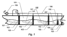
図1は、泡発生機構を含む船を概略的に示す。概して100と示される船は、この明細書中に記載されるように、船100に装着されるハル101と、1つ以上の泡発生機構102とを含む。各々の泡発生機構102は、供給ダクト106を介して泡発生機構102に圧縮空気を供給するための圧縮機105に対して供給ダクト106を通じて接続される。たとえば、圧縮機は、周囲空気を取込んで圧縮し、任意には、フロー剤を小量追加してもよい。船の後部に位置決めされた圧縮機が図1に示されているが、この圧縮機が船上の好適な如何なる位置にあってもよく、および/または、空気取込み口が好適な如何なる方向にも向けられ得ることが理解されるだろう。泡発生機構は、排出ノズル103を備え、そこから、圧縮空気が、ハルの周囲の水の境界層において微泡107を形成するように放出される。
FIG. 1 schematically shows a ship including a foam generating mechanism. A ship, generally designated 100, includes a
図1の例においては、複数の泡発生機構102は、船のハルの長さに沿って分散されたそれぞれの位置に配置される。各々の機構は、竜骨に近い位置からハルに沿って上向きに延在する。各々の機構102は、船が水中を移動する間、排出ノズル103から後方かつ上方に広がるそれぞれの微泡107の流れを発生させる。さまざまな実施例においては、機構の数および配置が異なっていてもよいことが認識されるだろう。たとえば、いくつかの実施例においては、たとえば船のハルの前部に配置された単一の機構で十分であり得るが、他の実施例においては、2つ、3つまたはそれ以上の機構が船のハルの長さに沿って分散されてもよい。各々の船について、機構の最適な数および配置は、模型および/もしくは流れシミュレーションによって、ならびに/または試行錯誤を行うことによって決定されてもよい。
In the example of FIG. 1, the plurality of
ノズルの孔を介して小さな泡を吹出す場合、マイクロメートルスケールの泡を発生させるために孔を可能な限り小さくするだけでは不十分であるかもしれない。この理由として、孔の端縁を形成する固体表面に対して成長した泡を付着させる湿潤力の存在が挙げられる。この固定力が阻害されない限り、その容積に比例する泡の浮力がこの泡に対する(典型的にはその接触外周部に比例する)固定抑制力を上回るまで、泡が成長することとなり、結果として破裂してしまう。この低圧力オフセットの場合には、力平衡により、通常、孔の直径よりも1回り大きなサイズの泡(the bubble at a size an order of magnitude larger than)を破裂させてしまう。さらに、固体表面の湿潤性が重要である。泡が孔の外周囲よりも広い領域にわたって表面と接触する場合、たとえば、固体表面が疎水性である場合、成長した泡の気相が、より広い区域にわたる固体表面との第2の固定力を発生させることとなり、浮力が大きくなる。このため、この浮力に打ち勝つための泡容積が必要となるだろう。表面が親水性であれば、この引力は存在しない。 When blowing small bubbles through the nozzle holes, it may not be sufficient to make the holes as small as possible to generate micrometer scale bubbles. The reason for this is the presence of a wetting force that causes the grown bubbles to adhere to the solid surface forming the edges of the pores. Unless this anchoring force is hindered, the bubble will grow until the bubble's buoyancy proportional to its volume exceeds the anchoring restraint force on this bubble (typically proportional to its contact periphery), resulting in a burst Resulting in. In the case of this low pressure offset, force balance typically causes the bubble at a size of order of magnitude larger than to burst. Furthermore, the wettability of the solid surface is important. When the foam contacts the surface over a larger area than the outer perimeter of the pore, for example, if the solid surface is hydrophobic, the gas phase of the grown foam will have a second anchoring force with the solid surface over a larger area. Will be generated and buoyancy will increase. This would require a bubble volume to overcome this buoyancy. This attractive force does not exist if the surface is hydrophilic.
小さい孔から泡を発生させることに伴う第2の問題点として、泡サイズの多分散性と、泡同士の間の間隔が不規則であることにより泡の大群が短時間で凝集してしまうこととが挙げられる。小さな泡が形成されたとしても、凝集によってその利点が直ちに減じられる可能性がある。 The second problem associated with generating bubbles from small pores is that large groups of bubbles aggregate in a short time due to polydispersity of the bubble size and irregular spacing between the bubbles. And so on. Even if small bubbles are formed, the benefits can be immediately reduced by agglomeration.
小さい孔から泡を発生させることに伴う第3の問題点は、細孔のノズル列におけるかまたは多孔性セラミック材料を通るチャネリングに関係している。形成されるうち最大の泡は、経路の抵抗を最小にしてしまい、ノズル列または多孔性セラミック材料における並行する浸透プロセス中に他のすべての泡よりも優先的に大きくなる。 A third problem with generating bubbles from small holes is related to channeling in the nozzle array of pores or through the porous ceramic material. The largest foam that is formed minimizes the resistance of the path and preferentially grows over all other foams during a parallel infiltration process in the nozzle row or porous ceramic material.
この明細書に開示される泡発生機構102の実施例においては、泡サイズが、上述の問題点のうち少なくともいくつかを回避するマイクロ流体装置によって制御される。
In the embodiment of the
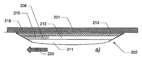
図2は、泡発生機構の断面図を概略的に示す。図2aは、機構の断面図を水平面で示す。船の前進中における船のハルに対する水の流れの方向は、矢印220によって示される。
FIG. 2 schematically shows a cross-sectional view of the bubble generating mechanism. FIG. 2a shows a cross-sectional view of the mechanism in a horizontal plane. The direction of water flow relative to the ship's hull during ship advance is indicated by
機構202は、基層213を有する層構造であり、この基層213の裏当て面は、接合層218によって、図2に図示のとおり船のハル201の外面に接合される。さらに、層構造202は、好適な接合技術によって、ともに挟まれる2つ以上の付加的な層211および212を含み得る。たとえば、機構の層は、ステンレス鋼で作られるかまたはプラスチックなどの1つ以上の他の好適な材料で作られ、船のハルに固定することのできる帯状体または板/薄板であってもよい。層211、212、213は、ともに溶接されてもよく、および/または、好適な接着材料、たとえばエポキシベースの材料によって接着されてもよい。基層は、溶接、好適な接着性物質、たとえばエポキシベースの接着性物質、磁石などによって船のハルに接合されてもよい。機構202は中間層212を含み、この中間層212に、1つ以上のマイクロ流体装置215、たとえばマイクロ流体発振器、がたとえば好適なエッチングプロセスによって埋込まれる。たとえば、流体装置215はスキンミル加工されてもよく、または化学的/静電的にステンレス鋼の帯状体にエッチングされてもよい。図2bは、中間層212の一部の断面図を垂直面で示したものであり、1列に配置された2つのマイクロ流体装置を示す。中間層が、1つ以上の列に配置された3つ以上の流体装置、たとえば、並んだ構成で配置されて1つ以上の列を形成する数百個またはさらには数千個のこのような装置、を含み得ることが認識されるだろう。概して、マイクロ流体装置215の1つ以上の列は、水面下の位置から船の竜骨に向かって下方に配置されてもよい。各々のマイクロ流体装置215は、マイクロ流体装置215に圧縮空気を供給する供給経路206に対してダクト214を介して接続される。各々のマイクロ流体装置は、マイクロ流体装置215によって排出される空気を排出ノズル203および204にそれぞれ供給する2つの排出ポートまたはダクト218および217を有する。中間層212はカバー層211によって覆われる。カバー層は凸状の外面を有していてもよく、それぞれの層の後縁および前縁は、全体的に翼状の形状を機構にもたらすように傾斜させられてもよい。
The
図2の例においては、機構は、単列のマイクロ流体装置を含む単一の中間層212を含む。代替的な実施例においては、機構は複数の中間層を含んでいてもよく、たとえば、これら複数の中間層はすべて、基層213とカバー層211との間に挟まれていてもよい。たとえば、マイクロ流体装置のさまざまな部分が、それぞれの層の表面にエッチングまたはミル加工されてもよく、その後、マイクロ流体装置を形成するように互いに位置合わせされ、接合されてもよい。代替的または付加的には、各々の中間層は、それぞれ一列のマイクロ流体装置を含んでもよく、これらの一列のマイクロ流体装置には、それぞれの供給ダクトによって圧縮空気が供給され、それぞれの列の排出ノズルが設けられている。このため、排出ノズルの数が増える可能性があり、および/または、マイクロ流体装置を備えた1つ以上の付加的な層を挿入することによって、さまざまな泡サイズを発生させるための複数列のノズルを構築することができる。さらに、基層および/またはカバー層はまた、マイクロ流体装置および/またはその部分を含み得る。
In the example of FIG. 2, the mechanism includes a single
図2の例においては、機構の後縁に位置決めされ、船の船尾に面するノズルが示される。しかしながら、代替的または付加的には、マイクロ流体装置が、帯状体の前縁および/または中央領域にそれらのノズルを備えて配置され得ることが認識されるだろう。 In the example of FIG. 2, a nozzle positioned at the trailing edge of the mechanism and facing the stern of the ship is shown. However, it will be appreciated that alternatively or additionally, microfluidic devices may be arranged with their nozzles at the leading edge and / or central region of the strip.
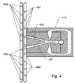
図3は、2つのノズル303および304のそれぞれに交互に供給を行うマイクロ流体発振器315を概略的に示す。発振器は、概して平坦な構成であるため、層構造の層のうち1つ以上、たとえば図2の中間層212、に配置することができる。マイクロ流体発振器315は、加圧空気または別の好適な泡形成流体のための供給経路に接続可能な入口ポート314と、分離路へと供給を行う噴流形成経路319とを備える。この分離路は、排出ポート303および304においてそれぞれ終端する1対の分岐経路316および317から構成される。排出ポートは、対応する排出ノズルを形成し得るかまたは対応する排出ノズルに接続され得る。これら対応する排出ノズルにおいては、泡形成流体が周囲の水中へと出て行き、泡を形成する。発振器はさらに制御経路321aおよび321bを含む。これら制御経路321aおよび321bは、噴流形成経路319の下流および上記対の分岐経路の上流において、発振器の相互作用区域322における向かい合った(流れ方向に対して)横方向のポートに接続される。図3の例においては、制御経路321aおよび321bは、フィードバックループ321cを介して互いと流体連通している。
FIG. 3 schematically shows a
使用時に、圧縮空気が、供給経路、たとえば図2の供給経路206、から入口ポート314に差込まれる。いくつかの実施例においては、噴流形成経路319の断面寸法が下流方向に向かって小さくなっていてもよく、これにより、注入された流れの速度が増し得る。空気流が相互作用区域322を通過すると、この流れにより、制御経路321aおよび321bにおける制御流体中に、振動する圧力波が形成される。制御流体は、液体または空気などの気体であってもよい。振動する圧力波は、分岐経路316および317のうちの1つに噴射流を押込む。制御流体中の圧力波がフィードバックループ321cを介して前後に振動すると、噴流が2つの分岐経路間で交互に切換えられ、こうして、分岐経路の各々において空気流の振動破裂を引起す。破裂が排出ポート303および304によって形成されるかまたは排出ポート303および304に接続される排出ノズルのうちの1つに達すると、気泡が生じる。泡の成長は、振動破裂の期間だけ、このため、発振器315の振動周波数によって、制限される。特に、泡が、同じ大きさの排出ノズルを通る空気の一定の流れによって発生させ得る泡よりも小さい間は、この泡の成長が止まる可能性がある。さらに、各々の分岐経路における破裂が相対位相差に応じて振動するので、泡が排出ノズル303および304から交互に発生し、こうして、隣接するノズルから生じる泡の分離を向上させる。制御経路がフィードバックループを形成するよう接続される場合、付加的な制御供給経路は不要である。振動破裂の頻度は、いくつかの方法で、たとえばフィードバックループの長さを変えることによって、選択することができるかまたはさらには変更することができる。
In use, compressed air is plugged into the
代替的な実施例においては、制御経路321aおよび321bが、フィードバックループによって互いに接続されることに加えて、または接続される代わりに、それぞれの制御供給経路に接続され得ることが認識されるだろう。このような実施例においては、制御供給経路は、たとえば以下の図7に関連付けて説明されるように、1つ以上の脈動圧力源、たとえば音源、に接続されてもよい。このため、マイクロ流体装置が増幅器として動作する可能性があり、この場合、脈動圧力波が制御経路321aおよび321bに加えられ、これにより、分岐経路において空気流の振動破裂がもたらされることとなる。脈動圧力源の周波数を制御することにより、発生させた泡のサイズが制御され得る。たとえば、液体を霧状化する文脈においてUS5,524,660に開示されるように、加圧空気の脈動破裂を発生させるためのマイクロ流体装置の代替的な実施例が用いられ得ることがさらに認識されるだろう。
It will be appreciated that in alternative embodiments,
層構造の板、薄板または他の層に形成されるマイクロ流体装置を設けることにより、泡発生機構は、比較的平坦な構造として実現されてもよく、これにより、抵抗を過度に増加させることなく、船のハルに当該機構を固定することが可能となる。たとえば、図2の層構造の合計厚みは、20mm未満、たとえば10mm未満、たとえば5〜7mmまたはさらにはそれ以下であり得る。 By providing a microfluidic device formed in a layered plate, lamina or other layer, the foam generation mechanism may be realized as a relatively flat structure, thereby preventing excessive increase in resistance. It becomes possible to fix the mechanism to the hull of the ship. For example, the total thickness of the layer structure of FIG. 2 may be less than 20 mm, such as less than 10 mm, such as 5-7 mm or even less.
いくつかの実施例においては、排出ノズル303および304を囲む表面、ならびに/または、少なくとも排出ノズル付近にある分岐経路の内面のうち少なくとも一部が、泡の放出を促進するために、好適なコーティング、たとえば疎水性コーティング、親水性コーティング、テフロン(登録商標)コーティングなどで覆われてもよい。
In some embodiments, the surface surrounding the
図4は、2セットのノズル403および404のそれぞれに対して交互に供給を行うマイクロ流体発振器415を概略的に示す。このように、各々の発振器または他のマイクロ流体装置がそれぞれのノズル列に供給を行い得るので、排出ノズルの数が増える可能性がある。
FIG. 4 schematically shows a
概して、いくつかの実施例においては、マイクロ流体装置の周波数は、たとえば、上述のとおりマイクロ流体増幅器の制御経路に加えられる圧力パルスの周波数を制御することによって、または、1つ以上のマイクロ流体発振器を他のマイクロ流体装置、たとえばマイクロ流体発振器に流れ込む圧縮空気の流れの圧力を変えるよう構成されたマイクロ流体増幅器、と組合せることによって、ならびに/または、他の場合には、たとえばマイクロ流体発振器に流れ込む圧縮空気のパラメータおよび/もしくはフィードバックループにおける制御流体のパラメータ、たとえば圧力および/もしくは温度、を変えることによって、制御可能である。たとえば、電熱線は、制御流体の温度を制御するための層構造に埋込まれてもよい。 In general, in some embodiments, the frequency of the microfluidic device is, for example, by controlling the frequency of pressure pulses applied to the control path of the microfluidic amplifier as described above, or one or more microfluidic oscillators In combination with other microfluidic devices, eg, microfluidic amplifiers configured to change the pressure of the flow of compressed air flowing into the microfluidic oscillator, and / or in other cases, eg, to the microfluidic oscillator It can be controlled by changing the parameters of the compressed air flowing in and / or the parameters of the control fluid in the feedback loop, for example pressure and / or temperature. For example, the heating wire may be embedded in a layer structure for controlling the temperature of the control fluid.
代替的には、機構は、各々が異なる周波数で動作することにより異なるサイズの泡を発生させるよう適合されたマイクロ流体発振器などの2セット以上のマイクロ流体装置を含み得る。これが示される図5においては、装置は、515a、515bおよび515cで示される3セットのマイクロ流体発振器を含んでおり、これら3セットのマイクロ流体発振器は、それぞれの供給経路506a、506b、506cによって供給を受ける。各セットのマイクロ流体発振器は、共通の振動周波数を有しているが、異なるセットのマイクロ流体発振器は、たとえばそれぞれのフィードバックループの長さによって規定されるさまざまな周波数を有する。結果として、当該セットのマイクロ流体装置のうちの1つに選択的に空気を供給することにより、異なるサイズの泡が作り出される可能性がある。
Alternatively, the mechanism may include two or more sets of microfluidic devices, such as microfluidic oscillators, each adapted to generate different sized bubbles by operating at different frequencies. In FIG. 5, where this is shown, the apparatus includes three sets of microfluidic oscillators, designated 515a, 515b and 515c, which are fed by
図5の機構は、図2に関連付けて説明されたとおり基層213ならびに付加的な2つの層212および211を含む層構造である点で、図2に示される機構と類似している。基層213は、船のハル201の外面に装着される。中間層212は、いくつかのマイクロ流体装置515aおよび515cと、対応する供給経路506aおよび506cとを含み、基層213とカバー層211との間に挟まれる。図5の実施例においては、カバー層211も構築され、さらなるセットのマイクロ流体装置515bおよび供給経路506bを含む。たとえば、マイクロ流体装置515aおよび515cは、カバー層に面する中間層の表面に設けられてもよく、マイクロ流体装置515bは、中間層に面するカバー層の表面に設けられてもよい。
The mechanism of FIG. 5 is similar to the mechanism shown in FIG. 2 in that it is a layered structure that includes a
各セットのマイクロ流体装置のうちいくつかのマイクロ流体装置は、それらの排出ノズルがそれぞれの列に配置されるように並んだ構成で配置される。図5においては、3つのマイクロ流体装置の列を含む機構の一部が示される。機構がそれぞれの列に配置される多数の装置を含み得ることが認識されるだろう。図5の実施例においては、マイクロ流体装置515aの排出ノズル503aおよび504aは機構の後縁に配置され、マイクロ流体装置515bの排出ノズル503bおよび504bは機構の中心線に沿って配置され、マイクロ流体装置515cの排出ノズル503cおよび504cは機構の前縁に配置される。
Some microfluidic devices of each set of microfluidic devices are arranged in a side-by-side configuration such that their discharge nozzles are arranged in respective rows. In FIG. 5, a portion of a mechanism comprising a row of three microfluidic devices is shown. It will be appreciated that the mechanism may include multiple devices arranged in each row. In the embodiment of FIG. 5, the
図6は、泡発生機構の別の実施例を概略的に示す。図6aは、泡発生機構の断面図を概略的に示す。図6の機構は、基層213、中間層212およびカバー層211を含む図2に示される実施例に類似している。図6b〜図6dは、それぞれの層の部分の上面図を示す。図示された部分は単一のマイクロ流体発振器を含む。しかしながら、機構が、並んだ構成で配置されたこのような多数の発振器を含み得ることが理解されるだろう。特に、図6bは、基層の一部、すなわち中間層に面する表面、の上面図を示す。図6cは、中間層212の一部の上面図を示し、図6dは、カバー層211の一部の底面図、すなわち中間層に面する表面を示している。図6の例においては、機構は、供給経路に接続された複数のマイクロ流体装置615を含む。3つの層がすべて構築されており、マイクロ流体装置615および/または供給経路のそれぞれの部分を備える。基層213は、マイクロ流体装置の主たるマイクロ流体構造、この場合、図3に関連付けて説明されたようにマイクロ流体発振器、を備える。基層に埋込まれた構造は、入口ポート314、噴流形成経路319、相互作用区域322、制御経路321aおよび321b、フィードバックループ321c、ならびに、それぞれの排出ポート603および604において終端する分岐経路316および317を含む。
FIG. 6 schematically shows another embodiment of the bubble generation mechanism. FIG. 6a schematically shows a cross-sectional view of the bubble generation mechanism. The mechanism of FIG. 6 is similar to the embodiment shown in FIG. 2 including a
中間層212は投入経路617と、排出経路633および644とを含む。中間層の投入経路および排出経路は、中間層全体を通って延在する穴を通るものとして形成され、それぞれ、投入ポート314ならびに分岐経路の終端603および604に揃えて位置合わせして形成される。こうして、投入経路617は、入口ポート314と供給経路606との間に流体連通をもたらす。カバー層211が中間層の幅全体にわたっては延在せず、中間層の表面の端縁部分を露出させたままにしているため、排出経路633および644は機構の外面へと延在し、こうして、それぞれの排出ノズルを形成する。カバー層211は、供給経路606を、たとえばカバー層の底面における細長い凹部の形状で含む。
The
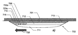
図7は、泡発生機構の断面図を概略的に示す。図7aは、機構の断面図を水平面で示す。船の前進中に船のハルに対して相対的に水が流れる方向が矢印720によって示される。
FIG. 7 schematically shows a cross-sectional view of the bubble generating mechanism. FIG. 7a shows a cross-sectional view of the mechanism in a horizontal plane. The direction of water flow relative to the ship's hull during ship advance is indicated by
機構702は、それが、基層713を有する層構造として形成され、この基層713の裏当て面が、図7に図示のとおり接合層718によって船のハル701の外面に接合される点で、図2の機構に類似している。さらに、層構造702は、図2に関連付けて全てが説明されたとおり、好適な接合技術によってともに挟まれる2つ以上の付加的な層711および712を含み得る。
The
機構702は、中間層712を含み、この中間層712には、図2に関連付けて説明したとおり、たとえば好適なエッチングプロセスによって1つ以上のマイクロ流体装置715、たとえばマイクロ流体発振器、が埋込まれる。図7bは、中間層712の一部の断面図を垂直面で示したものであり、1列に配置された2つのマイクロ流体装置を示す。
各々のマイクロ流体装置715は、マイクロ流体装置715に圧縮空気を供給する供給経路706に対してダクト714を介して接続される、各々のマイクロ流体装置は2つの排出ポートまたはダクト716および717を有し、これら2つの排出ポートまたはダクト716および717は、それぞれ、マイクロ流体装置715によって排出ノズル703および704に排出される空気を供給する。中間層712は、図2に関連付けて全て説明されたように、カバー層711によって覆われる。マイクロ流体装置715は、それぞれ、2つのノズル703および704に交互に供給を行うマイクロ流体発振器である。マイクロ流体発振器715は、それが、図3に関連付けて全て説明されたとおり、加圧空気のための供給経路706に接続された入口ポート714と、排出ポート703および704においてそれぞれ終端する1対の分岐経路716および717からなる分離路に対して供給を行う噴流形成経路719とを有する点で、図3に示されるマイクロ流体発振器に類似している。発振器は制御経路721aおよび721bをさらに含む。これら制御経路721aおよび721bは、噴流形成経路719の下流および上記対の分岐経路の上流において、発振器の相互作用区域722における向かい合った(流れ方向に対して)横方向のポートに接続される。
Each
図7の機構は、以下の点で図2の機構および図3のマイクロ流体発振器とは異なる。すなわち、制御経路721aおよび721bがそれぞれの制御供給経路723aおよび723bに接続され、これにより、制御経路の各々と、加圧空気または別の好適な流体の制御流れを制御経路721aおよび721bにそれぞれ供給するための制御供給経路のそれぞれとの間に流体連通をもたらすようにしている点である。各々の制御供給経路は、対応する脈動圧力源(明確には図示せず)、たとえば音源、に接続される。脈動圧力源は加圧空気の脈動圧力を与えるよう制御される。特に、圧力源は、脈動圧力源によって課される周波数で発振器715を振動させるようにするために、同じ周波数で、但し互いに対して期間の半分だけ位相をずらした状態で、制御経路721aおよび721bにおける圧力を変えるよう制御されてもよい。
The mechanism of FIG. 7 differs from the mechanism of FIG. 2 and the microfluidic oscillator of FIG. 3 in the following points. That is,
図8は、各々が異なる周波数で動作することにより異なるサイズの泡を発生させるよう適合されたマイクロ流体発振器などの複数セットのマイクロ流体装置を含む機構の別の例を示す。機構802は、たとえば図5に関連付けて説明されたとおり、各々が供給経路806a、806b、806cからそれぞれ供給を受ける3セットのマイクロ流体発振器(それぞれ815a、815bおよび815cと示される)を含む。各セットのマイクロ流体発振器は共通の振動周波数を有しているが、異なるセットのマイクロ流体発振器は、たとえばそれぞれのフィードバックループの長さによって規定される異なる周波数を有する。結果として、当該セットのマイクロ流体装置のうちの1つに選択的に空気または別の流体を供給することにより、異なるサイズの泡が作り出される可能性がある。このために、供給経路806a〜806cが、流れセレクタ875と流体連通するよう接続され、この流れセレクタ875がさらに、流体管876を介して流体源805、たとえば空気を圧縮するための圧縮機、に接続される。こうして、泡形成流体が、流体源から流れセレクタ875に供給される。この流れセレクタ875は、供給経路806a〜806cのうちの1つと、このため当該セットのマイクロ流体装置815a〜815cのうちの1つとに対して流体を選択的に方向付けるよう制御可能である。
FIG. 8 shows another example of a mechanism that includes multiple sets of microfluidic devices, such as microfluidic oscillators, each adapted to generate bubbles of different sizes by operating at different frequencies. The
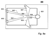
図9aは、この発明のいくつかの実施例に従ったマイクロ流体装置900を示す。マイクロ流体装置は、入口ポート901、第1の経路902、第2の経路904、第1の制御経路907、および第2の制御経路909を含む。第1の経路902および第2の経路904は、中央チャンバ906を介して入口ポート901、第1の制御経路907および第2の制御経路909と流体連通している。第1の経路902は、微泡を発生させるための第1のノズル903を含む。第2の経路は、微泡を発生させるための第2のノズル905を含む。第1の制御経路907は第1の制御入口908を含み、第2の制御経路909は第2の制御入口910を含む。第1の制御経路907は、第1の制御出口908および第2の制御出口910が上記フィードバック経路を介して直接流体連通するように、フィードバック経路によって第2の制御経路909に接続されてもよい。加えて、または代替的には、第1の制御経路907および/または第2の制御経路909は、制御流れを発生させるよう構成された制御システムと流体連通していてもよい。
FIG. 9a shows a
図9bは、この発明のいくつかの実施例に従ったマイクロ流体装置900を示す。ここで、マイクロ流体装置は経路およびノズルをそれぞれ1つしか含まない。
FIG. 9b shows a
いくつかの実施例を詳細に記載および図示してきたが、本発明はこれらに限定されず、添付の特許請求の範囲に規定される主題の範囲内で他の方法で具体化されてもよい。特に、他の実施例が利用されてもよく、構造的かつ機能的な変形例もこの発明の範囲から逸脱することなく実施可能であることが理解されるはずである。 Although several embodiments have been described and illustrated in detail, the present invention is not limited thereto and may be embodied in other ways within the scope of the subject matter defined in the appended claims. In particular, it should be understood that other embodiments may be utilized and that structural and functional variations may be implemented without departing from the scope of the present invention.
いくつかの手段を列挙する装置クレームにおいては、これらの手段のうちいくつかは、ハードウェアのうち全く同一のアイテムによって具体化することができる。いくつかの方策が相互に異なる従属請求項に記載されるかまたはさまざまな実施例において説明されているが、これは単に、これらの方策の組合せを有利に用いることができないことを示しているわけではない。 In the device claim enumerating several means, several of these means can be embodied by one and the same item of hardware. Several measures are described in mutually different dependent claims or described in various embodiments, but this merely indicates that a combination of these measures cannot be used to advantage. is not.
この明細書で用いられる場合、「含む(comprises/comprising)」という語は、記載された特徴、整数、ステップまたは構成要素の存在を特定するものとされるが、1つ以上の他の特徴、整数、ステップ、構成要素またはこれらの群の存在または追加を排除するものではないことが強調されなければならない。 As used herein, the term “comprises / comprising” is intended to identify the presence of the described feature, integer, step or component, but one or more other features, It should be emphasized that it does not exclude the presence or addition of integers, steps, components or groups thereof.
Claims (26)
− 流体の流れを供給するための入口ポートと、
− 船のハルに対する抵抗を低減させるための流体の泡を発生させるための第1のノズルを含む第1の経路とを含み、前記第1の経路は、中央チャンバを介して前記入口ポートと流体連通しており、前記少なくとも1つのマイクロ流体装置はさらに、
− 前記第1のノズルを通る流れを制御するよう構成された第1の制御入口を含む第1の制御経路を含み、前記第1の制御入口は、前記中央チャンバを介して前記入口ポートおよび前記第1の経路と流体連通している、請求項1または2に記載の機構。 At least one microfluidic device is
-An inlet port for supplying a fluid flow;
A first path comprising a first nozzle for generating a fluid bubble for reducing resistance to the hull of the ship, said first path being connected to the inlet port and the fluid via a central chamber In communication, the at least one microfluidic device further comprises:
-Including a first control path including a first control inlet configured to control flow through the first nozzle, the first control inlet passing through the central chamber and the inlet port and the The mechanism of claim 1 or 2 in fluid communication with the first path.
− 船のハルに対する抵抗を低減させるための流体の泡を発生させるための第2のノズルを含む第2の経路を含み、前記第2の経路は、前記中央チャンバを介して前記入口ポートおよび前記第1の制御入口と流体連通しており、前記第1の制御入口はさらに、前記第2のノズルを介して流れを制御するよう構成される、請求項1から3に記載の機構。 The at least one microfluidic device further includes
-A second path comprising a second nozzle for generating a fluid bubble for reducing resistance to the hull of the ship, said second path through said central chamber and said inlet port and said The mechanism according to claim 1, wherein the mechanism is in fluid communication with a first control inlet, the first control inlet further configured to control flow through the second nozzle.
− 前記第1のノズルおよび前記第2のノズルを通る流れを制御するための第2の制御入口を含む第2の制御経路を含み、前記第2の制御入口は、前記中央チャンバを介して、前記入口ポート、前記第1のノズル、前記第2のノズルおよび前記第1の制御入口と流体連通している、請求項4から6のいずれかに記載の機構。 The at least one microfluidic device further includes
-Including a second control path including a second control inlet for controlling flow through the first nozzle and the second nozzle, the second control inlet via the central chamber; The mechanism of any of claims 4 to 6, wherein the mechanism is in fluid communication with the inlet port, the first nozzle, the second nozzle and the first control inlet.
− ハルの外面に対して、請求項1から23のいずれかに記載の機構を取付けるステップと、
− 機構の排出ノズルを通じて前記泡発生流体を水中に排出することにより、ハルと前記ハルの周囲の水との間の境界において泡発生流体の泡を発生させるステップと、
− 時間の経過とともに変化する流れである泡形成流体の流れを供給することにより、発生させた泡のサイズを制御するステップとを含む、方法。 A method for reducing the resistance of a ship to hull,
Attaching the mechanism according to any of claims 1 to 23 to the outer surface of the hull;
-Generating foam generating fluid bubbles at the boundary between the hull and the water surrounding the hull by discharging the foam generating fluid into the water through a discharge nozzle of the mechanism;
-Controlling the size of the generated foam by providing a flow of foam-forming fluid that is a flow that changes over time.
Applications Claiming Priority (5)
| Application Number | Priority Date | Filing Date | Title |
|---|---|---|---|
| US35738010P | 2010-06-22 | 2010-06-22 | |
| US61/357,380 | 2010-06-22 | ||
| DKPA201070283A DK201070283A (en) | 2010-06-22 | 2010-06-22 | Reducing drag of a hull of a ship |
| DKPA201070283 | 2010-06-22 | ||
| PCT/EP2011/060497 WO2011161187A1 (en) | 2010-06-22 | 2011-06-22 | Reducing drag of a hull of a ship |
Publications (2)
| Publication Number | Publication Date |
|---|---|
| JP2013529570A true JP2013529570A (en) | 2013-07-22 |
| JP2013529570A5 JP2013529570A5 (en) | 2014-08-14 |
Family
ID=43533001
Family Applications (1)
| Application Number | Title | Priority Date | Filing Date |
|---|---|---|---|
| JP2013515893A Pending JP2013529570A (en) | 2010-06-22 | 2011-06-22 | Reduced resistance to ship hulls |
Country Status (9)
| Country | Link |
|---|---|
| US (1) | US9611010B2 (en) |
| EP (1) | EP2585364B8 (en) |
| JP (1) | JP2013529570A (en) |
| KR (1) | KR101820663B1 (en) |
| CN (1) | CN103079949B (en) |
| DK (2) | DK201070283A (en) |
| ES (1) | ES2492692T3 (en) |
| SG (1) | SG186426A1 (en) |
| WO (1) | WO2011161187A1 (en) |
Families Citing this family (20)
| Publication number | Priority date | Publication date | Assignee | Title |
|---|---|---|---|---|
| NO335909B1 (en) * | 2012-06-14 | 2015-03-23 | Nader Hassavari | Procedure for air-driven propulsion of a vessel and air-driven vessel |
| US20160273562A1 (en) * | 2013-10-03 | 2016-09-22 | Ramot At Tel-Aviv University Ltd. | System and method for multiple direction control of flow |
| CA2950999A1 (en) | 2014-06-11 | 2015-12-17 | Monotricat Srl C.R. | Hull for low drag boats |
| NO20140995A1 (en) * | 2014-08-22 | 2016-02-23 | Zhu Yi | Use of high pressure air to reduce resistance on ships |
| JP6484902B2 (en) * | 2015-03-31 | 2019-03-20 | 三菱重工業株式会社 | Friction resistance reduction device for air lubricated ship, ship |
| WO2016178642A1 (en) * | 2015-05-06 | 2016-11-10 | Cemal İNCEOĞLU | Air flow apparatus for accelerating maritime vessels |
| USD817248S1 (en) * | 2015-11-11 | 2018-05-08 | Hermitage Fo Sarl | Bow portion of a ship hull |
| CN106005242A (en) * | 2016-05-27 | 2016-10-12 | 武汉理工大学 | Air-lubricated ship |
| WO2018039813A1 (en) * | 2016-09-02 | 2018-03-08 | 杨一男 | Air cavity craft |
| US10315729B2 (en) | 2016-11-30 | 2019-06-11 | Kevin M McPherson | Ship hull microbubble system |
| CN107117256A (en) * | 2017-03-03 | 2017-09-01 | 江苏省太仓中等专业学校 | A kind of ship air damping device and method |
| EP3833878A4 (en) * | 2018-08-07 | 2022-05-04 | The Regents of The University of California | Air layer and hydrophobic drag reduction and preferential guidance and recovery of gas with engineered surfaces |
| CN109131720A (en) * | 2018-09-01 | 2019-01-04 | 哈尔滨工程大学 | A kind of water medium-high speed sports body Friction Reduction by Micro-bubbles structure |
| KR102120781B1 (en) * | 2018-11-21 | 2020-06-17 | 한국해양과학기술원 | Method for improving antifouling performance of active anti-fouling surface using active gas generation |
| CN110304193B (en) * | 2019-07-11 | 2020-07-03 | 上海海事大学 | Anti-bubble drag reduction method and system for ship |
| EP3896685A1 (en) | 2020-04-17 | 2021-10-20 | Marine Performance Systems BV | Device for attenuating underwater sound pressure, and use of such a device |
| EP3895974A1 (en) | 2020-04-17 | 2021-10-20 | Marine Performance Systems BV | Belt and method for reducing the drag of a hull of a floating vessel |
| USD991412S1 (en) | 2021-02-01 | 2023-07-04 | Parker Maritime Technologies, LLC | Air dispersal module |
| NL2030857B1 (en) | 2022-02-09 | 2023-09-07 | Alfa Laval Rotterdam B V | A method for providing a hull of a vessel with bubble generators |
| CN116424476B (en) * | 2023-06-13 | 2023-10-20 | 招商局金陵船舶(威海)有限公司 | Ship body bubble drag reduction device |
Citations (3)
| Publication number | Priority date | Publication date | Assignee | Title |
|---|---|---|---|---|
| JPH09240571A (en) * | 1996-03-12 | 1997-09-16 | Ishikawajima Harima Heavy Ind Co Ltd | Frictional resistance reducing device of ship |
| WO2009122736A1 (en) * | 2008-04-01 | 2009-10-08 | 独立行政法人海上技術安全研究所 | Frictional resistance reduction device for ship |
| JP2010508143A (en) * | 2006-10-30 | 2010-03-18 | ザ ユニバーシティー オブ シェフィールド | Foam generation for aeration and other purposes |
Family Cites Families (19)
| Publication number | Priority date | Publication date | Assignee | Title |
|---|---|---|---|---|
| KR100188464B1 (en) * | 1993-05-11 | 1999-06-01 | 다께이 도시후미 | Method and device of reducing friction on a navigating vehicle |
| US5524660A (en) | 1995-06-28 | 1996-06-11 | Basf Corporation | Plate-type spray nozzle and method of use |
| US5613456A (en) * | 1995-07-28 | 1997-03-25 | The United States Of America As Represented By The Secretary Of The Navy | Microbubble positioning and control system |
| WO1997020728A1 (en) * | 1995-12-04 | 1997-06-12 | Ishikawajima-Harima Heavy Industries Co., Ltd. | Method of reducing friction resistance of hull, ship whose friction resistance is reduced by the method, and method of analyzing jetted bubbles on ship |
| JPH10119875A (en) * | 1996-10-15 | 1998-05-12 | Ishikawajima Harima Heavy Ind Co Ltd | Micro bubble generater |
| JPH10175587A (en) * | 1996-12-19 | 1998-06-30 | Ishikawajima Harima Heavy Ind Co Ltd | Frictional resistance reducing device for ship |
| JPH1149080A (en) | 1997-08-01 | 1999-02-23 | Ishikawajima Harima Heavy Ind Co Ltd | Bubble generating method, friction reducing ship and friction reducing method |
| JPH11152077A (en) | 1997-11-20 | 1999-06-08 | Ishikawajima Harima Heavy Ind Co Ltd | Friction reduced ship and friction reducing method of hull |
| CA2244615A1 (en) * | 1997-08-22 | 1999-02-22 | Ishikawajima-Harima Heavy Industries Co., Ltd. | Friction-reducing ship with compressed air generation apparatus, friction reduction apparatus and gas jetting device |
| US6145459A (en) * | 1997-12-19 | 2000-11-14 | Ishikawajima-Harima Heavy Industries Co., Ltd. | Friction-reducing ship and method for reducing skin friction |
| JP2000062682A (en) | 1998-08-24 | 2000-02-29 | Shojiro Akusawa | Bubble generator for ship |
| US6789491B2 (en) * | 2000-04-03 | 2004-09-14 | Ishikawajima-Harima Heavy Industries Co., Ltd. | Friction reducing ship and method for reducing frictional resistance |
| US6356816B1 (en) * | 2000-09-15 | 2002-03-12 | The United States Of America As Represented By The Secretary Of The Navy | Method and apparatus for reducing drag in marine vessels |
| JP3984089B2 (en) * | 2001-03-29 | 2007-09-26 | 三星重工業株式会社 | Drag reduction method and apparatus by ship surface turbulence control |
| CN2652812Y (en) | 2003-10-17 | 2004-11-03 | 武汉理工大学 | Resistance reducing micro bubble generator |
| US6932012B1 (en) | 2004-02-09 | 2005-08-23 | Richard B. Philips | Multi-hull surface vessel with drag reduction on lateral hulls |
| US7080664B1 (en) * | 2005-05-20 | 2006-07-25 | Crystal Fountains Inc. | Fluid amplifier with media isolation control valve |
| GB2429435A (en) | 2005-08-23 | 2007-02-28 | Alexander Walter Swales | Ship or boat hull air lubrication system |
| JP4183048B1 (en) * | 2008-04-17 | 2008-11-19 | 有限会社ランドエンジニアリング | Friction resistance reducing ship and its operating method |
-
2010
- 2010-06-22 DK DKPA201070283A patent/DK201070283A/en not_active Application Discontinuation
-
2011
- 2011-06-22 JP JP2013515893A patent/JP2013529570A/en active Pending
- 2011-06-22 US US13/806,060 patent/US9611010B2/en active Active
- 2011-06-22 ES ES11726826.8T patent/ES2492692T3/en active Active
- 2011-06-22 SG SG2012094207A patent/SG186426A1/en unknown
- 2011-06-22 KR KR1020137001595A patent/KR101820663B1/en active IP Right Grant
- 2011-06-22 EP EP11726826.8A patent/EP2585364B8/en active Active
- 2011-06-22 CN CN201180040174.5A patent/CN103079949B/en active Active
- 2011-06-22 DK DK11726826.8T patent/DK2585364T3/en active
- 2011-06-22 WO PCT/EP2011/060497 patent/WO2011161187A1/en active Application Filing
Patent Citations (3)
| Publication number | Priority date | Publication date | Assignee | Title |
|---|---|---|---|---|
| JPH09240571A (en) * | 1996-03-12 | 1997-09-16 | Ishikawajima Harima Heavy Ind Co Ltd | Frictional resistance reducing device of ship |
| JP2010508143A (en) * | 2006-10-30 | 2010-03-18 | ザ ユニバーシティー オブ シェフィールド | Foam generation for aeration and other purposes |
| WO2009122736A1 (en) * | 2008-04-01 | 2009-10-08 | 独立行政法人海上技術安全研究所 | Frictional resistance reduction device for ship |
Also Published As
| Publication number | Publication date |
|---|---|
| KR20130052603A (en) | 2013-05-22 |
| CN103079949B (en) | 2015-12-02 |
| WO2011161187A1 (en) | 2011-12-29 |
| EP2585364B8 (en) | 2014-08-27 |
| US20130269589A1 (en) | 2013-10-17 |
| EP2585364A1 (en) | 2013-05-01 |
| ES2492692T3 (en) | 2014-09-10 |
| DK201070283A (en) | 2012-02-02 |
| SG186426A1 (en) | 2013-01-30 |
| US9611010B2 (en) | 2017-04-04 |
| DK2585364T3 (en) | 2014-08-18 |
| EP2585364B1 (en) | 2014-05-14 |
| CN103079949A (en) | 2013-05-01 |
| KR101820663B1 (en) | 2018-01-22 |
Similar Documents
| Publication | Publication Date | Title |
|---|---|---|
| JP2013529570A (en) | Reduced resistance to ship hulls | |
| KR101249166B1 (en) | Device for reducing frictional resistance of ship body | |
| JP2013529570A5 (en) | ||
| EP2081666B1 (en) | Bubble generation for aeration and other purposes | |
| KR100441723B1 (en) | Friction-reducing ship and method for reducing skin friction | |
| US8011310B2 (en) | Ship with reduced frictional resistance and its operation method | |
| US10744468B2 (en) | System and method for feeding gas into liquid | |
| JP4044840B2 (en) | Method and apparatus for enhancing the effectiveness and efficiency of multiple boundary layer control techniques | |
| JP2016538184A (en) | Flat bottom ship and method for controlling length of at least one air cavity | |
| JP6554511B2 (en) | Three-dimensional contracted airflow nozzle and method for its use | |
| JP2003265939A (en) | Apparatus and method for generating air bubble, and apparatus and method for producing fine particle | |
| JPH0747264A (en) | Method for foaming and apparatus therefor | |
| JPH08230763A (en) | Equipment for generating micro bubble | |
| JP7092358B2 (en) | Ultra-fine bubble generator and ultra-fine bubble generator | |
| JPH10281115A (en) | Fluid control method | |
| US20160273562A1 (en) | System and method for multiple direction control of flow | |
| JP5082093B2 (en) | Friction resistance reduction method for hull | |
| US9915274B2 (en) | Acoustic pumps and systems | |
| CN113829245B (en) | Nano jet polishing device | |
| CN111344067B (en) | Multi-blade ultrasonic gas nozzle for liquid bubbling | |
| RU1782220C (en) | Aerodynamic member of aircraft | |
| CN113994105A (en) | Fluidic oscillator | |
| JP4331014B2 (en) | Chemical oxygen iodine laser device | |
| JP2015529554A (en) | Cross-flow type bubble generator and method for generating the same | |
| JP2005280416A (en) | Free motion object in fluid |
Legal Events
| Date | Code | Title | Description |
|---|---|---|---|
| A521 | Written amendment |
Free format text: JAPANESE INTERMEDIATE CODE: A523 Effective date: 20140620 |
|
| A621 | Written request for application examination |
Free format text: JAPANESE INTERMEDIATE CODE: A621 Effective date: 20140620 |
|
| A711 | Notification of change in applicant |
Free format text: JAPANESE INTERMEDIATE CODE: A711 Effective date: 20140903 |
|
| A521 | Written amendment |
Free format text: JAPANESE INTERMEDIATE CODE: A821 Effective date: 20140903 |
|
| A977 | Report on retrieval |
Free format text: JAPANESE INTERMEDIATE CODE: A971007 Effective date: 20150626 |
|
| A131 | Notification of reasons for refusal |
Free format text: JAPANESE INTERMEDIATE CODE: A131 Effective date: 20150630 |
|
| A601 | Written request for extension of time |
Free format text: JAPANESE INTERMEDIATE CODE: A601 Effective date: 20150925 |
|
| A02 | Decision of refusal |
Free format text: JAPANESE INTERMEDIATE CODE: A02 Effective date: 20160301 |