JP2013521139A - Machining tool with ultra fine adjustment without backlash - Google Patents
Machining tool with ultra fine adjustment without backlash Download PDFInfo
- Publication number
- JP2013521139A JP2013521139A JP2012555358A JP2012555358A JP2013521139A JP 2013521139 A JP2013521139 A JP 2013521139A JP 2012555358 A JP2012555358 A JP 2012555358A JP 2012555358 A JP2012555358 A JP 2012555358A JP 2013521139 A JP2013521139 A JP 2013521139A
- Authority
- JP
- Japan
- Prior art keywords
- threaded
- drive shaft
- machining tool
- slider
- slider element
- Prior art date
- Legal status (The legal status is an assumption and is not a legal conclusion. Google has not performed a legal analysis and makes no representation as to the accuracy of the status listed.)
- Pending
Links
Images


Classifications
-
- B—PERFORMING OPERATIONS; TRANSPORTING
- B23—MACHINE TOOLS; METAL-WORKING NOT OTHERWISE PROVIDED FOR
- B23B—TURNING; BORING
- B23B29/00—Holders for non-rotary cutting tools; Boring bars or boring heads; Accessories for tool holders
- B23B29/03—Boring heads
- B23B29/034—Boring heads with tools moving radially, e.g. for making chamfers or undercuttings
-
- B—PERFORMING OPERATIONS; TRANSPORTING
- B23—MACHINE TOOLS; METAL-WORKING NOT OTHERWISE PROVIDED FOR
- B23B—TURNING; BORING
- B23B27/00—Tools for turning or boring machines; Tools of a similar kind in general; Accessories therefor
- B23B27/14—Cutting tools of which the bits or tips or cutting inserts are of special material
- B23B27/16—Cutting tools of which the bits or tips or cutting inserts are of special material with exchangeable cutting bits or cutting inserts, e.g. able to be clamped
-
- B—PERFORMING OPERATIONS; TRANSPORTING
- B23—MACHINE TOOLS; METAL-WORKING NOT OTHERWISE PROVIDED FOR
- B23B—TURNING; BORING
- B23B29/00—Holders for non-rotary cutting tools; Boring bars or boring heads; Accessories for tool holders
- B23B29/03—Boring heads
- B23B29/034—Boring heads with tools moving radially, e.g. for making chamfers or undercuttings
- B23B29/03403—Boring heads with tools moving radially, e.g. for making chamfers or undercuttings radially adjustable before starting manufacturing
- B23B29/03407—Boring heads with tools moving radially, e.g. for making chamfers or undercuttings radially adjustable before starting manufacturing by means of screws and nuts
-
- B—PERFORMING OPERATIONS; TRANSPORTING
- B23—MACHINE TOOLS; METAL-WORKING NOT OTHERWISE PROVIDED FOR
- B23B—TURNING; BORING
- B23B2260/00—Details of constructional elements
- B23B2260/056—Differential screw threads
-
- B—PERFORMING OPERATIONS; TRANSPORTING
- B23—MACHINE TOOLS; METAL-WORKING NOT OTHERWISE PROVIDED FOR
- B23B—TURNING; BORING
- B23B2260/00—Details of constructional elements
- B23B2260/136—Springs
-
- Y—GENERAL TAGGING OF NEW TECHNOLOGICAL DEVELOPMENTS; GENERAL TAGGING OF CROSS-SECTIONAL TECHNOLOGIES SPANNING OVER SEVERAL SECTIONS OF THE IPC; TECHNICAL SUBJECTS COVERED BY FORMER USPC CROSS-REFERENCE ART COLLECTIONS [XRACs] AND DIGESTS
- Y10—TECHNICAL SUBJECTS COVERED BY FORMER USPC
- Y10T—TECHNICAL SUBJECTS COVERED BY FORMER US CLASSIFICATION
- Y10T408/00—Cutting by use of rotating axially moving tool
- Y10T408/83—Tool-support with means to move Tool relative to tool-support
- Y10T408/85—Tool-support with means to move Tool relative to tool-support to move radially
- Y10T408/858—Moving means including wedge, screw or cam
- Y10T408/8583—Moving means including wedge, screw or cam with resiliently urged Tool
Abstract
本発明は、工具本体(4、9)と、工具本体(4、9)の開口の中に少なくとも部分的に受け入れられると共に第一位置と第二位置との間で調整方向に工具本体に対して移動可能なスライダ要素(3、7)と、2つのネジ部を有する(図5参照)駆動シャフト(8、10)と、を備える機械加工工具(1)であって、スライダ要素(3、7)及び工具本体(4、9)は各々ネジ部を有し(図5参照)、駆動シャフト(8、10)をその軸線回りに回転させると、スライダ要素(3、7)を第一位置と第二位置との間で本体(4、9)に対して移動できるように、駆動シャフト(8、10)の第一ネジ部はスライダ要素(3、7)のネジ部と協働し、駆動シャフト(8、10)の第二ネジ部は本体(4、9)のネジ部と協働する、機械加工工具に関する。スライダ要素(3、7)を両方の調整方向に工具本体(4、9)に対してほぼバックラッシュ無しの超微細な調整を可能にするために、スライダ要素(3、7)と係合するばね要素(13)が設けられ、ばね要素は、スライダ要素(3、7)が2つの位置の一方の方向に前もって張力を与えるように配置される。 The present invention relates to a tool body (4, 9) and at least partially received in the opening of the tool body (4, 9) and with respect to the tool body in an adjusting direction between a first position and a second position. A machining tool (1) comprising a movable slider element (3, 7) and a drive shaft (8, 10) having two threaded parts (see FIG. 5), the slider element (3, 7) and the tool body (4, 9) each have a threaded portion (see FIG. 5), and when the drive shaft (8, 10) is rotated about its axis, the slider elements (3, 7) are moved to the first position. The first threaded portion of the drive shaft (8, 10) cooperates with the threaded portion of the slider element (3, 7) so that it can move relative to the body (4, 9) between A machining tool in which the second threaded part of the drive shaft (8, 10) cooperates with the threaded part of the body (4, 9) About. Engage the slider element (3, 7) with the slider element (3, 7) in order to allow ultra-fine adjustment with almost no backlash to the tool body (4, 9) in both adjustment directions A spring element (13) is provided, which is arranged such that the slider element (3, 7) pre-tensions in one direction of the two positions.
Description
本発明は、工具本体と、工具本体の開口の中に少なくとも部分的に受け入れられると共に第一位置と第二位置との間で調整方向に工具本体に対して移動可能なスライダ要素と、2つのネジ部を有する駆動シャフトと、を備える機械加工工具に関する。スライダ要素及び工具本体は、各々、それぞれのネジ部を有し、駆動シャフトをその軸線回りに回転させると、スライダ要素を第一位置と第二位置との間で本体に対して移動できるように、駆動シャフトの第一ネジ部がスライダ要素のネジ部と協働し、かつ駆動シャフトの第二ネジ部が工具本体のネジ部と協働する。 The present invention comprises a tool body, a slider element that is at least partially received in the opening of the tool body and is movable relative to the tool body in an adjusting direction between a first position and a second position, The present invention relates to a machining tool including a drive shaft having a screw portion. The slider element and the tool body each have a respective threaded portion so that when the drive shaft is rotated about its axis, the slider element can be moved relative to the body between the first position and the second position. The first screw portion of the drive shaft cooperates with the screw portion of the slider element, and the second screw portion of the drive shaft cooperates with the screw portion of the tool body.
このような機械加工工具はすでに長いこと知られている。例えば、工具本体を有し、その端部に工具本体に対して調整可能なスライダ要素が設置されている穿孔工具が知られている。スライダ要素は半径方向に移動可能である。スライダ要素は、機械加工対象のワークピースと直接当接するように設置された切削部、または切削ビットを受け入れる座を有する。 Such machining tools have been known for a long time. For example, a drilling tool having a tool body and having a slider element that can be adjusted with respect to the tool body at an end thereof is known. The slider element is movable in the radial direction. The slider element has a seat for receiving a cutting bit or cutting bit that is placed in direct contact with the workpiece to be machined.
既知の構造体において、スライダ要素は、ネジ部によって工具本体に取り付けられた駆動シャフトと係合するので、スライダ要素は、駆動シャフトの回転によって半径方向に往復できる。使用時に、スライダ要素は対応する切削ビットを支えるので、駆動シャフトによって穿孔工具の穿孔半径を調整できる。 In the known structure, the slider element engages with a drive shaft attached to the tool body by a threaded portion, so that the slider element can reciprocate in the radial direction by rotation of the drive shaft. In use, the slider element supports the corresponding cutting bit so that the drilling radius of the drilling tool can be adjusted by means of the drive shaft.
多くの使用状況において、工具本体に対する工具キャリアの高度に精密な調整が望まれる。従って、既知の機械加工工具において、駆動シャフトのネジ部及び工具本体の対応するネジ部は、細目ネジの形式であることが多い。 In many situations of use, a highly precise adjustment of the tool carrier relative to the tool body is desired. Thus, in known machining tools, the threaded part of the drive shaft and the corresponding threaded part of the tool body are often in the form of fine threads.
原則として、細目ネジは、微細になればなるほど、より複雑化し、生産がよりコスト高になる。 As a general rule, the finer the screw, the more complex and the more expensive the production.
細目ネジの複雑でコスト高な製造を回避しながら、超微細調整を可能にするために、すでに、駆動シャフトが工具本体の対応するネジ部と協働する第二ネジ部を有し、駆動シャフトの2つのネジ部がピッチ及び(または)回転方向の点で相互に異なることが、特許文献1において提案されている。 In order to allow ultra-fine adjustment while avoiding complicated and costly production of fine threads, the drive shaft already has a second threaded portion that cooperates with the corresponding threaded portion of the tool body, and the drive shaft It has been proposed in Patent Document 1 that the two screw portions are different from each other in terms of pitch and / or rotational direction.
既知の構成を用いて、非常に微細な調整が可能である。しかし、この既知の構成の場合、ネジ部の使用は対応するネジ斜面の遊びを伴うので、調整方向へ構成体を回転させたとき別個の作業において調整済みの穿孔半径を測定する必要がある。調整方向を逆転させたとき、まず、駆動要素の回転運動がスライダ要素の半径方向運動に変換されるまで、2つのネジ部のネジ斜面遊びを引き締めなければならないので、駆動シャフトの調整位置に基づきスライダ要素の半径方向の位置を充分に高い精度で推定することができない。 Very fine adjustments are possible using known configurations. However, in the case of this known configuration, the use of the screw part involves play of the corresponding screw bevel, so that it is necessary to measure the adjusted drilling radius in a separate operation when the component is rotated in the adjusting direction. When the adjustment direction is reversed, the screw slope play of the two screw portions must first be tightened until the rotational movement of the drive element is converted into the radial movement of the slider element. The position of the slider element in the radial direction cannot be estimated with sufficiently high accuracy.
上述の技術現状に基づき、本発明の目的は、本明細書の冒頭で述べた種類の機械加工工具を提供することである。この工具においては、両方の調整方向において工具本体に対して、ほぼバックラッシュなしのスライダ要素の超微細調整が可能である。 Based on the above state of the art, the object of the present invention is to provide a machining tool of the kind mentioned at the beginning of the description. In this tool, the slider element can be finely adjusted substantially without backlash with respect to the tool body in both adjustment directions.
本発明によれば、スライダ要素と係合すると共にスライダ要素の2つの位置の一方の方向にスライダ要素を付勢するように配置されたばね要素が設けられるという点で、上記の目的が達成される。 According to the invention, the above object is achieved in that a spring element is provided which engages the slider element and is arranged to bias the slider element in one direction of the two positions of the slider element. .
例えば半径方向外向きのスライダ要素の付勢によって、いずれの位置においても、同じネジ斜面の側部が相互に係合する。駆動シャフトの回転方向が逆転したとき、ばね要素によってスライダ要素の対抗運動を直ちに実施できる。一方、現状技術の構成においては、係合したねじ部が相互にネジ斜面から離れるまで、これらの遊びのため、当初、駆動シャフトだけが反対方向に移動する。 For example, due to the biasing of the radially outward slider element, the sides of the same screw bevel engage each other at any position. When the direction of rotation of the drive shaft is reversed, the opposing movement of the slider element can be carried out immediately by the spring element. On the other hand, in the configuration of the state of the art, only the drive shaft initially moves in the opposite direction due to these play until the engaged screw parts are separated from the screw slope.
好ましい実施形態において、駆動要素のネジ部は雄ネジの形式をとり、本体及びスライダ要素のネジ部は雌ネジの形式をとる。従って、本体は、駆動要素の対応するネジ部を受け入れる雌ネジを持つ対応する孔を持つことができる。スライダ要素は、スリーブ形の形態を持つことができ、スリーブは、駆動要素の対応する雄ネジ部と係合する雌ネジ部を持つ。 In a preferred embodiment, the threaded portion of the drive element takes the form of an external thread, and the threaded portion of the body and slider element takes the form of an internal thread. The body can thus have a corresponding hole with an internal thread that receives a corresponding threaded portion of the drive element. The slider element can have a sleeve-shaped configuration, the sleeve having a female threaded portion that engages with a corresponding male threaded portion of the drive element.
有利なことに、駆動要素の2つのネジ部はネジピッチ及び(または)回転方向が異なる。従って、一方のネジ部、例えば本体のネジ部のネジピッチは0.2〜0.7mm/回転であり、他方のネジ部例えばスライダ要素のネジ部のネジピッチは0.1〜0.5mm/回転であり、両方のネジ部が右ネジを持つか、または両方のネジ部が左ネジを持つ。このような措置は、その結果のスライダ要素の運動が2つのネジピッチの相違から生じることを意味する。 Advantageously, the two threaded portions of the drive element have different thread pitches and / or rotational directions. Therefore, the screw pitch of one screw portion, for example, the screw portion of the main body is 0.2 to 0.7 mm / rotation, and the screw pitch of the other screw portion, for example, the screw portion of the slider element is 0.1 to 0.5 mm / rotation. Yes, both threads have a right-hand thread, or both threads have a left-hand thread. Such a measure means that the resulting movement of the slider element results from the difference between the two screw pitches.
さらに好ましい実施形態において、駆動シャフトは、2つのネジ部を持つ二重ネジ付き要素と駆動要素とを備えるように二部構成を持つ。二重ネジ付き要素及び駆動要素は、調整方向に相互に対して移動可能であることが好ましい。ただし、好ましい実施形態において、二重ネジ付き要素及び駆動要素は、シャフトの軸線回りの回転方向に積極的に固締関係で一体的に接続される。好ましくは、積極的固締接続は、実質的に溝形の開口と溝形の開口内で係合する実質的に刃形の要素とによって形成される。この場合、溝形開口は、二重ネジ付き要素(これは好ましい実施形態に対応する)あるいは駆動要素に設置でき、刃形要素は他方の要素に配置される。すなわち、好ましい実施形態においては、駆動要素に配置される。溝形開口への刃形要素の係合は、駆動要素の回転によってトルクを積極的固締関係にある二重ネジ付き要素へ伝達できることを意味する。 In a further preferred embodiment, the drive shaft has a two-part configuration with a double threaded element with two threaded parts and a drive element. The double threaded element and the drive element are preferably movable relative to each other in the adjusting direction. However, in a preferred embodiment, the double threaded element and the drive element are positively connected together in a positive locking relationship in the direction of rotation about the axis of the shaft. Preferably, the positive fastening connection is formed by a substantially groove-shaped opening and a substantially blade-shaped element that engages within the groove-shaped opening. In this case, the channel opening can be placed in a double threaded element (which corresponds to a preferred embodiment) or a drive element, the blade element being arranged in the other element. That is, in a preferred embodiment, it is arranged on the drive element. The engagement of the blade element in the channel opening means that the torque can be transmitted to the double threaded element in a positive clamping relationship by rotation of the drive element.
二重ネジ付き要素の工具本体へのネジ式接続は、駆動要素の作動時に、スライダ要素だけでなく二重ネジ付き要素も、調整方向に(例えば、工具本体に対して半径方向に)、ただし互いに異なる程度で移動させることを可能にする。駆動要素及び二重ネジ付き要素が刃形要素及び溝方開口によって接続されることにより、調整装置の機能性を害することなく調整方向において駆動要素をその位置に保持できる。従って、現状技術の構成と異なり、スライダ要素を調整すると、駆動要素は本体の孔の中及び外へ回転せず、調整方向、例えば半径方向において所定の位置を維持する。 The threaded connection of the double-threaded element to the tool body means that when the drive element is activated, not only the slider element but also the double-threaded element is in the adjusting direction (eg in the radial direction with respect to the tool body), It is possible to move to different degrees. The drive element and the double threaded element are connected by the blade element and the grooved opening, so that the drive element can be held in position in the adjustment direction without compromising the functionality of the adjustment device. Thus, unlike the state of the art configuration, when the slider element is adjusted, the drive element does not rotate into and out of the hole in the body and maintains a predetermined position in the adjustment direction, eg, the radial direction.
好ましい実施形態において、駆動シャフトは、複数の凹部または溝を有するスプライン部を有する。工具本体は弾性突起物を有し、突起物は、駆動シャフトが回転すると、スプライン部の複数の凹部に順次係合するように、スプライン部に対して配置される。このように、弾性突起物は、例えば、ばね要素で付勢された圧力部の形式を取ることができる。この措置によって、機械加工工具の使用者は、駆動要素を調整するときにこれを感じることができ、概して聞くこともできるというフィードバックを得る。対応する溝は、例えば、弾性突起物が1つの溝から次の溝に係合する程度に駆動要素が回転することによって、スライダ要素が1/1000mmだけ変位するように、等間隔に配置できる。 In a preferred embodiment, the drive shaft has a spline portion having a plurality of recesses or grooves. The tool main body has an elastic protrusion, and the protrusion is arranged with respect to the spline portion so as to sequentially engage with the plurality of concave portions of the spline portion when the drive shaft rotates. Thus, the elastic protrusion can take the form of a pressure portion biased by a spring element, for example. This measure provides feedback that the user of the machining tool can feel and generally hear when adjusting the drive element. Corresponding grooves can be arranged at equal intervals so that the slider elements are displaced by 1/1000 mm, for example, by rotating the drive element to the extent that the elastic protrusion engages from one groove to the next.
特定の好ましい実施形態において、本体のネジ部及び(または)スピンドル要素のネジ部は、スリーブによって形成される。スリーブは、別個のものであるが、本体及びスピンドル要素においてそれぞれ固定的に接続される。スリーブは、青銅亜鉛鋳造合金から形成されることが好ましい。 In certain preferred embodiments, the threads of the body and / or the threads of the spindle element are formed by sleeves. The sleeves are separate but are fixedly connected at the body and the spindle element, respectively. The sleeve is preferably formed from a bronze zinc cast alloy.
本発明のさらなる利点、特徴及び可能な使用法は、好ましい実施形態の以下の説明及び添付図面から明らかになる。 Further advantages, features and possible uses of the present invention will become apparent from the following description of preferred embodiments and the accompanying drawings.
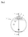
図1は、本発明の1つの実施形態を示す。スライダ要素3に保持された切削ビット2を持つ機械加工工具1を、下面からの図で示す。図面を強調して明白にするために、スライダ要素3の中の切削ビット2のホルダは図示しない。
FIG. 1 illustrates one embodiment of the present invention. A machining tool 1 with a
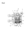
図2の断面図から、スライダ要素3が工具本体4の適切な階段状孔に受け入れられることが分かる。スライダ要素は、実質的にスリーブ形態であり、回転防止手段5によって軸線6回りの回転が防止される。
It can be seen from the cross-sectional view of FIG. 2 that the
スライダ要素3の内部に、スライダ要素3と固定的に接続されたブッシュ7が配置される。ブッシュは、例えばガンメタル(砲金)から製造できる。ブッシュ7は、本明細書の冒頭で述べたスライダ要素のネジ部を提供する雌ネジを有する。スライダ要素3は、より大きい内径を持つ工具本体ハウジングの孔の部分の内径に対応する外径を持つ。ブッシュ7の雌ネジは、二重ネジ付きスピンドルのネジ部と係合する。二重ネジ付きスピンドル8は、本体4に接続された本体ブッシュ9と係合する第二ネジ部を有する。本体ブッシュ9も、ガンメタルから製造できる。二重ネジ付きスピンドルは、ソードスピンドル(sword spindle)10の形式の駆動要素と一緒に駆動シャフトを形成する。二重ネジ付きスピンドル8は、溝形開口を有し、この中に、ソードスピンドル10のプレート形のまたは刃形の部分が係合する。
A
ソードスピンドル10は、工具本体階段状孔の小さい方の直径の部分に、脚要素11によって保持される。
The
ソードスピンドル10は、スライダ要素の調整及び切削ビット2の正確な位置のために長手軸線6回りに回転できる。ソードスピンドルの刃形要素は、二重ネジ付きスピンドルの溝形開口の中に嵌合するので、ソードスピンドル10の回転運動は二重ネジ付きスピンドル8に伝達される。二重ネジ付きスピンドル8は、本体ブッシュ9のネジ部において延びているので、当該回転運動は二重ネジ付きスピンドル8の半径方向の運動を引き起こす。好ましい実施形態において、本体ブッシュ9は、1回転あたり0.3mmのネジピッチを有する。
The
同時に、二重ネジ付きスピンドル8は、好ましい実施形態において1回転あたり0.25mmのピッチを持つ第二ネジ部をスライダブッシュ7の雌ネジの中へ係合させる。その結果、第二ネジ部がスライダ要素3を二重ネジ付きスピンドル8に対して半径方向に移動させるときに、スライダ要素3は、二重ネジ付きスピンドル8をその周囲全体にわたって半径方向に移動させないことになる。その結果、スライダ要素は、2つのネジピッチの間の差、すなわちソードスピンドルの1回転に付き0.05mm移動する。
At the same time, the double-threaded
従って、スライダ要素3は、ソードスピンドル10を回転させることによって、半径方向に微細に調整できる。ナイフ形または刃形部分15の他に、ソードスピンドル10は円板部分14を有する。円板は、その外縁に、凹部を形成する複数の溝を有する。
Therefore, the
特に図4から分かるように、工具本体4の中に弾力的に付勢される圧力部16が配置される。圧力部は、ソードスピンドル10の円板形部分14の対応する溝に係合する。スピンドル10を回転させると、圧力部16がソードスピンドル10の円板形部分14の対応する溝の中にラッチ式に係合するのを聞いて感じることできる。
As can be seen in particular from FIG. 4, a
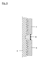
円板形要素14が、例えば50の等間隔に配列された溝を持つ場合、各「クリック」すなわちソードスピンドル10の1回転の1/50、ひいては1つの溝から別の溝への回転がスライダ要素3の1/1000mmの半径方向の運動に対応するように、対応するネジ部のネジピッチを選択できる。本発明によれば、図解される実施形態において、本体4または本体4に固定された本体ブッシュ9及びスライダ要素3の両方に係合して、スライダ要素3を外向きに、すなわちソードスピンドル10から離れるように圧迫するばね要素13が設置される。関係するネジ部は必然的にある程度の遊びを持つので、図5に概略的に示す状況が生じる。それぞれ係合しているネジ部は、それぞれ左側ネジ斜面または右側ネジ斜面のみに係止していることが分かる。スライダ要素3がソードスピンドル10によって半径方向外向きに動かされたときにも、この状況が生じる。しかし、ソードスピンドル10の回転方向が逆転するならば、すなわちスライダ要素3を本体4の中へさらに動かすならば、ばね要素13がないと、ネジ斜面の遊びは、まず本体ブッシュ9と二重ネジ付きスピンドルとの間の第一ネジ接続部において引き締められ、次の段階においてネジ斜面の遊びは、二重ネジ付きスピンドル8とスライダブッシュ7との間で引き締められる。両方のネジ接続部がネジ斜面を変えた後でなければ、ソードスピンドルのさらなる回転によってスライダ要素3は移動しない。
If the disk-shaped
上述の形態の場合、スプリング要素13がないと、スライダ要素を反対方向に動かす前に、ソードスピンドルを15から20「クリック」すなわち15/50から20/50回転させなければならない可能性がある。従って、スライダ要素3の正確な位置に関してソードスピンドル10の位置から結論を引き出すことはできない。
In the case of the configuration described above, without the
本発明によるばね要素13の構成は、二重ネジ付きスピンドルの第一ネジ部においても、第二ネジ部においても、ネジ斜面の遊びによるネジ斜面の変更を効果的に防止する。斜面の変更がないと、2つのネジ部は完全に遊びがない状態を維持し、その結果、この発明では実際上、ソードスピンドル10の位置に基づいて、切削ビット2の半径方向の位置に関して結果に達することができる。従って、図1〜4に示す実施形態は、さらに、スケールディスク12を備え、これに基づいて、ソードスピンドル10の回転位置を読み取ることができる。
The configuration of the
1 機械加工工具
2 切削ビット
3 スライダ要素
4 工具本体
5 回転防止手段
6 軸線
7 スライダブッシュ
8 二重ネジ付きスピンドル
9 本体ブッシュ
10 ソードスピンドル
11 脚要素
12 スケールディスク
13 ばね要素
14 円板形部分
15 刃形部分
16 圧力部
DESCRIPTION OF SYMBOLS 1
Claims (9)
前記スライダ要素及び前記工具本体が、各々、それぞれのネジ部を有し、
前記駆動シャフトをその軸線回りに回転させると、前記スライダ要素を前記第一位置と第二位置との間で前記本体に対して移動できるように、前記駆動シャフトの第一ネジ部が前記スライダ要素の前記ネジ部と協働し、かつ前記駆動シャフトの第二ネジ部が前記本体の前記ネジ部と協働する、
機械加工工具において、
前記スライダ要素に係合すると共に前記2つの位置の一方の方向に前記スライダ要素を付勢するように配置されたばね要素が設けられることを特徴とする、
機械加工工具。 A tool body, a slider element that is at least partially received in the opening of the tool body and is movable relative to the tool body in a direction of adjustment between a first position and a second position; and two threaded portions A machining tool comprising: a drive shaft having
The slider element and the tool body each have a respective threaded portion;
When the drive shaft is rotated about its axis, the first threaded portion of the drive shaft is adapted to move the slider element relative to the body between the first position and the second position. And the second threaded portion of the drive shaft cooperates with the threaded portion of the body.
In machining tools,
A spring element arranged to engage the slider element and bias the slider element in one direction of the two positions,
Machining tool.
好ましくは、前記積極的固締関係が、実質的に溝形の開口と前記溝形開口内で係合する実質的に刃形の要素とによって形成され、
前記溝形開口が、前記二重ネジ付き要素または前記駆動要素に配置され、前記刃形要素が他方の要素に配置されることを特徴とする、
請求項5または6に記載の機械加工工具。 The double threaded element and the drive element are integrally connected in a positive clamping relationship in the direction of rotation about the axis of the shaft;
Preferably, the positive clamping relationship is formed by a substantially groove-shaped opening and a substantially blade-shaped element engaging within the groove-shaped opening;
The groove-shaped opening is arranged in the double-threaded element or the drive element, and the blade-shaped element is arranged in the other element,
The machining tool according to claim 5 or 6.
Applications Claiming Priority (3)
| Application Number | Priority Date | Filing Date | Title |
|---|---|---|---|
| DE102010002557A DE102010002557A1 (en) | 2010-03-03 | 2010-03-03 | Cutting tool with backlash-free fine adjustment |
| DE102010002557.7 | 2010-03-03 | ||
| PCT/EP2011/052424 WO2011107357A1 (en) | 2010-03-03 | 2011-02-18 | Machining tool having zero-backlash ultrafine adjustment |
Publications (2)
| Publication Number | Publication Date |
|---|---|
| JP2013521139A true JP2013521139A (en) | 2013-06-10 |
| JP2013521139A5 JP2013521139A5 (en) | 2013-12-19 |
Family
ID=43983302
Family Applications (1)
| Application Number | Title | Priority Date | Filing Date |
|---|---|---|---|
| JP2012555358A Pending JP2013521139A (en) | 2010-03-03 | 2011-02-18 | Machining tool with ultra fine adjustment without backlash |
Country Status (7)
| Country | Link |
|---|---|
| US (1) | US20130209188A1 (en) |
| EP (1) | EP2542367A1 (en) |
| JP (1) | JP2013521139A (en) |
| KR (1) | KR20130038191A (en) |
| CN (1) | CN103079734A (en) |
| DE (1) | DE102010002557A1 (en) |
| WO (1) | WO2011107357A1 (en) |
Cited By (2)
| Publication number | Priority date | Publication date | Assignee | Title |
|---|---|---|---|---|
| JP6251358B1 (en) * | 2016-11-14 | 2017-12-20 | 株式会社日研工作所 | Boring tools |
| JP2020528359A (en) * | 2017-07-28 | 2020-09-24 | ギューリング カーゲーGuehring Kg | Cutting tool with adjustment device |
Families Citing this family (3)
| Publication number | Priority date | Publication date | Assignee | Title |
|---|---|---|---|---|
| KR101337591B1 (en) * | 2012-05-07 | 2013-12-06 | (주) 테크노라이즈 | Use is convenient minute height adjusting device for fixing of tool |
| CN108500307A (en) * | 2018-04-23 | 2018-09-07 | 成都成林数控刀具有限公司 | A kind of Miniature adjustable double-blade boring cutter |
| WO2020239897A1 (en) | 2019-05-29 | 2020-12-03 | Big Kaiser Präzisionswerkzeuge Ag | Boring head with a mechanism for clamping a displaceable tool carrier |
Citations (4)
| Publication number | Priority date | Publication date | Assignee | Title |
|---|---|---|---|---|
| GB1071055A (en) * | 1963-09-11 | 1967-06-07 | Wickman Wimet Ltd | Adjustable tool for use with boring bars and other tool holders |
| US3709625A (en) * | 1971-05-06 | 1973-01-09 | Ingersoll Milling Machine Co | Cutting tooth mounting for coarse and fine adjustment |
| JP2006305723A (en) * | 2005-04-26 | 2006-11-09 | Heinz Kaiser Ag | Boring tool |
| US20070084320A1 (en) * | 2005-09-23 | 2007-04-19 | Sandvik Intellectual Property Ab | Cutting tool with very fine adjustment |
Family Cites Families (16)
| Publication number | Priority date | Publication date | Assignee | Title |
|---|---|---|---|---|
| US1697509A (en) * | 1924-02-20 | 1929-01-01 | Jr John M Marty | Expansible reamer |
| US3323193A (en) * | 1965-12-16 | 1967-06-06 | Walter J Greenleaf Jr | Cutting tool cartridge insert |
| US3447403A (en) * | 1968-06-17 | 1969-06-03 | Allegheny Ludlum Steel | Adjustable boring unit |
| US3682561A (en) * | 1971-01-18 | 1972-08-08 | Raymond E Lemery | Cutter tooth mounting for fine wear adjustment |
| US3741672A (en) * | 1971-07-29 | 1973-06-26 | N Hedberg | Adjustable tool holder |
| US3937587A (en) * | 1974-07-05 | 1976-02-10 | The Ingersoll Milling Machine Company | Adjustable cutter tooth mounting |
| US4428704A (en) * | 1980-07-28 | 1984-01-31 | Ex-Cell-O Corporation | Micro-adjusting cartridge for cutting tool |
| DE3446275C1 (en) * | 1984-12-19 | 1986-07-24 | Samson Ag, 6000 Frankfurt | Rotating drill head with an infeed device arranged between a connecting shank and a tool carrier |
| EP0483807A3 (en) * | 1990-11-02 | 1992-09-02 | Kiyoshi Miyashita | Boring bar |
| DE4330822A1 (en) * | 1993-09-13 | 1995-03-16 | Komet Stahlhalter Werkzeug | Tool head for use in machine tools |
| FR2747563B1 (en) * | 1996-04-17 | 1998-06-05 | Micro Mega Int Mfg Sa | HANDLE FOR ROTARY DENTAL INSTRUMENT |
| JP3740915B2 (en) * | 1999-10-21 | 2006-02-01 | 三菱マテリアル株式会社 | Cutting tools |
| US6846136B2 (en) * | 2002-08-06 | 2005-01-25 | Velenite Inc. | Rotatable cutting tool |
| FI20050916A0 (en) * | 2005-09-14 | 2005-09-14 | Mandrel Oy | Arrangement in the cutting tool |
| US7753626B2 (en) * | 2007-01-18 | 2010-07-13 | Kennametal Inc. | Micro-adjustable differential screw assembly |
| DE102007041447B3 (en) * | 2007-08-31 | 2009-04-16 | Kieninger Gmbh | Fixing arrangement for cutting tool of boring bar, has cutting center support and supporting element with coactive contact surfaces, where cutting center support and supporting element are arranged one after another |
-
2010
- 2010-03-03 DE DE102010002557A patent/DE102010002557A1/en not_active Withdrawn
-
2011
- 2011-02-18 KR KR1020127022862A patent/KR20130038191A/en not_active Application Discontinuation
- 2011-02-18 WO PCT/EP2011/052424 patent/WO2011107357A1/en active Application Filing
- 2011-02-18 EP EP11705508A patent/EP2542367A1/en not_active Withdrawn
- 2011-02-18 JP JP2012555358A patent/JP2013521139A/en active Pending
- 2011-02-18 US US13/581,828 patent/US20130209188A1/en not_active Abandoned
- 2011-02-18 CN CN2011800123010A patent/CN103079734A/en active Pending
Patent Citations (4)
| Publication number | Priority date | Publication date | Assignee | Title |
|---|---|---|---|---|
| GB1071055A (en) * | 1963-09-11 | 1967-06-07 | Wickman Wimet Ltd | Adjustable tool for use with boring bars and other tool holders |
| US3709625A (en) * | 1971-05-06 | 1973-01-09 | Ingersoll Milling Machine Co | Cutting tooth mounting for coarse and fine adjustment |
| JP2006305723A (en) * | 2005-04-26 | 2006-11-09 | Heinz Kaiser Ag | Boring tool |
| US20070084320A1 (en) * | 2005-09-23 | 2007-04-19 | Sandvik Intellectual Property Ab | Cutting tool with very fine adjustment |
Cited By (4)
| Publication number | Priority date | Publication date | Assignee | Title |
|---|---|---|---|---|
| JP6251358B1 (en) * | 2016-11-14 | 2017-12-20 | 株式会社日研工作所 | Boring tools |
| JP2018079517A (en) * | 2016-11-14 | 2018-05-24 | 株式会社日研工作所 | Boring tool |
| JP2020528359A (en) * | 2017-07-28 | 2020-09-24 | ギューリング カーゲーGuehring Kg | Cutting tool with adjustment device |
| JP7237060B2 (en) | 2017-07-28 | 2023-03-10 | ギューリング カーゲー | Cutting tool with adjusting device |
Also Published As
| Publication number | Publication date |
|---|---|
| WO2011107357A1 (en) | 2011-09-09 |
| EP2542367A1 (en) | 2013-01-09 |
| DE102010002557A1 (en) | 2011-09-08 |
| CN103079734A (en) | 2013-05-01 |
| KR20130038191A (en) | 2013-04-17 |
| US20130209188A1 (en) | 2013-08-15 |
Similar Documents
| Publication | Publication Date | Title |
|---|---|---|
| US11154940B2 (en) | Hole saw arbor assembly | |
| JP2013521139A (en) | Machining tool with ultra fine adjustment without backlash | |
| WO2008053528A1 (en) | Tap holder | |
| JP2013220528A (en) | Hydraulic expansion chuck | |
| US8267631B2 (en) | Fitting member positioning device | |
| US7186064B1 (en) | Rotary tapered tool holder with adapter sleeve | |
| JP2011528285A (en) | Axis adjustable tool | |
| WO2019075930A1 (en) | Helical gear having gap-eliminating device | |
| JP2009125828A (en) | Outer diameter minutely adjustable boring bar | |
| JP6048772B1 (en) | Cutting machine and scissors | |
| KR101666363B1 (en) | back lash adjusting device for screw and boring bar using it | |
| WO2014167984A1 (en) | Cutting tool for machining nut in sliding screw device and method for machining nut | |
| JP2006263828A (en) | Cutting tool | |
| JP2011189446A (en) | Tap holder | |
| US20140161551A1 (en) | Rotary Tool, In Particular Reaming Tool and Adjustment Element For a Rotary Tool | |
| US2918291A (en) | Toolholder adapter | |
| JP5780188B2 (en) | Clamping mechanism of cutting member and blade part exchangeable cutting tool using the same | |
| US1079630A (en) | Expansible reamer. | |
| CN101870010B (en) | Assembly for connecting a tool wheel and a tool holder | |
| JP2008307966A (en) | Rack guide device | |
| JP2013136129A (en) | Tap collet | |
| JP2011115888A (en) | Tool holder | |
| JP2008044031A (en) | Self-aligning tool holder | |
| CN109862980B (en) | Working machine having position correction function and position correction method for working machine | |
| JP5990478B2 (en) | Drilling tool |
Legal Events
| Date | Code | Title | Description |
|---|---|---|---|
| A521 | Written amendment |
Free format text: JAPANESE INTERMEDIATE CODE: A523 Effective date: 20131029 |
|
| A621 | Written request for application examination |
Free format text: JAPANESE INTERMEDIATE CODE: A621 Effective date: 20131029 |
|
| A131 | Notification of reasons for refusal |
Free format text: JAPANESE INTERMEDIATE CODE: A131 Effective date: 20140812 |
|
| A601 | Written request for extension of time |
Free format text: JAPANESE INTERMEDIATE CODE: A601 Effective date: 20141111 |
|
| A602 | Written permission of extension of time |
Free format text: JAPANESE INTERMEDIATE CODE: A602 Effective date: 20141118 |
|
| A521 | Written amendment |
Free format text: JAPANESE INTERMEDIATE CODE: A523 Effective date: 20150212 |
|
| A131 | Notification of reasons for refusal |
Free format text: JAPANESE INTERMEDIATE CODE: A131 Effective date: 20150707 |
|
| A02 | Decision of refusal |
Free format text: JAPANESE INTERMEDIATE CODE: A02 Effective date: 20151201 |