DE102010002557A1 - Cutting tool with backlash-free fine adjustment - Google Patents
Cutting tool with backlash-free fine adjustment Download PDFInfo
- Publication number
- DE102010002557A1 DE102010002557A1 DE102010002557A DE102010002557A DE102010002557A1 DE 102010002557 A1 DE102010002557 A1 DE 102010002557A1 DE 102010002557 A DE102010002557 A DE 102010002557A DE 102010002557 A DE102010002557 A DE 102010002557A DE 102010002557 A1 DE102010002557 A1 DE 102010002557A1
- Authority
- DE
- Germany
- Prior art keywords
- threaded
- cutting tool
- drive shaft
- threaded portion
- base body
- Prior art date
- Legal status (The legal status is an assumption and is not a legal conclusion. Google has not performed a legal analysis and makes no representation as to the accuracy of the status listed.)
- Withdrawn
Links
Images


Classifications
-
- B—PERFORMING OPERATIONS; TRANSPORTING
- B23—MACHINE TOOLS; METAL-WORKING NOT OTHERWISE PROVIDED FOR
- B23B—TURNING; BORING
- B23B29/00—Holders for non-rotary cutting tools; Boring bars or boring heads; Accessories for tool holders
- B23B29/03—Boring heads
- B23B29/034—Boring heads with tools moving radially, e.g. for making chamfers or undercuttings
-
- B—PERFORMING OPERATIONS; TRANSPORTING
- B23—MACHINE TOOLS; METAL-WORKING NOT OTHERWISE PROVIDED FOR
- B23B—TURNING; BORING
- B23B27/00—Tools for turning or boring machines; Tools of a similar kind in general; Accessories therefor
- B23B27/14—Cutting tools of which the bits or tips or cutting inserts are of special material
- B23B27/16—Cutting tools of which the bits or tips or cutting inserts are of special material with exchangeable cutting bits or cutting inserts, e.g. able to be clamped
-
- B—PERFORMING OPERATIONS; TRANSPORTING
- B23—MACHINE TOOLS; METAL-WORKING NOT OTHERWISE PROVIDED FOR
- B23B—TURNING; BORING
- B23B29/00—Holders for non-rotary cutting tools; Boring bars or boring heads; Accessories for tool holders
- B23B29/03—Boring heads
- B23B29/034—Boring heads with tools moving radially, e.g. for making chamfers or undercuttings
- B23B29/03403—Boring heads with tools moving radially, e.g. for making chamfers or undercuttings radially adjustable before starting manufacturing
- B23B29/03407—Boring heads with tools moving radially, e.g. for making chamfers or undercuttings radially adjustable before starting manufacturing by means of screws and nuts
-
- B—PERFORMING OPERATIONS; TRANSPORTING
- B23—MACHINE TOOLS; METAL-WORKING NOT OTHERWISE PROVIDED FOR
- B23B—TURNING; BORING
- B23B2260/00—Details of constructional elements
- B23B2260/056—Differential screw threads
-
- B—PERFORMING OPERATIONS; TRANSPORTING
- B23—MACHINE TOOLS; METAL-WORKING NOT OTHERWISE PROVIDED FOR
- B23B—TURNING; BORING
- B23B2260/00—Details of constructional elements
- B23B2260/136—Springs
-
- Y—GENERAL TAGGING OF NEW TECHNOLOGICAL DEVELOPMENTS; GENERAL TAGGING OF CROSS-SECTIONAL TECHNOLOGIES SPANNING OVER SEVERAL SECTIONS OF THE IPC; TECHNICAL SUBJECTS COVERED BY FORMER USPC CROSS-REFERENCE ART COLLECTIONS [XRACs] AND DIGESTS
- Y10—TECHNICAL SUBJECTS COVERED BY FORMER USPC
- Y10T—TECHNICAL SUBJECTS COVERED BY FORMER US CLASSIFICATION
- Y10T408/00—Cutting by use of rotating axially moving tool
- Y10T408/83—Tool-support with means to move Tool relative to tool-support
- Y10T408/85—Tool-support with means to move Tool relative to tool-support to move radially
- Y10T408/858—Moving means including wedge, screw or cam
- Y10T408/8583—Moving means including wedge, screw or cam with resiliently urged Tool
Abstract
Die vorliegende Erfindung betrifft ein Zerspanungswerkzeug mit einem Werkzeuggrundkörper, einem zumindest teilweise in einer Öffnung des Werkzeuggrundkörpers aufgenommenen und relativ zu diesem in einer Einstellrichtung zwischen einer ersten und einer zweiten Position bewegbaren Schieberelement und einer Antriebswelle mit zwei Gewindeabschnitten, wobei das Schieberelement und der Werkzeuggrundkörper jeweils einen Gewindeabschnitt aufweisen, wobei der erste Gewindeabschnitt der Antriebswelle mit dem Gewindeabschnitt des Schieberelementes und der zweite Gewindeabschnitt der Antriebswelle mit dem Gewindeabschnitt des Grundkörpers derart zusammenwirken, dass beim Drehen der Antriebswelle um ihre Achse das Schieberelement relativ zum Grundkörper zwischen der ersten und der zweiten Position bewegt werden kann. Um ein Zerspanungswerkzeug der eingangs genannten Art bereitzustellen, mit welchem nahezu spielfrei eine Feinstverstellung des Schieberelementes in Bezug auf den Werkzeuggrundkörper in beiden Einstellrichtungen möglich ist, wird erfindungsgemäß vorgeschlagen, dass ein am Schieberelement angreifendes Federelement vorgesehen ist, welct in Richtung einer der zwei Positionen vorgespannt ist.The present invention relates to a cutting tool with a tool base body, a slide element which is at least partially received in an opening of the tool base body and can be moved relative thereto in an adjustment direction between a first and a second position, and a drive shaft with two threaded sections, the slide element and the tool base body each having one Have threaded section, the first threaded section of the drive shaft interacting with the threaded section of the slide element and the second threaded section of the drive shaft with the threaded section of the base body in such a way that when the drive shaft rotates around its axis, the slide element is moved relative to the base body between the first and the second position can. In order to provide a cutting tool of the type mentioned at the outset, with which a very fine adjustment of the slide element with respect to the tool base body is possible in both adjustment directions with almost no play, it is proposed according to the invention that a spring element engaging the slide element is provided, which is biased towards one of the two positions .
Description
Die vorliegende Erfindung betrifft ein Zerspanungswerkzeug mit einem Werkzeuggrundkörper, einem zumindest teilweise in einer Öffnung des Werkzeuggrundkörpers aufgenommenen und relativ zu diesem in einer Einstellrichtung zwischen einer ersten und einer zweiten Position bewegbaren Schieberelement und einer Antriebswelle mit zwei Gewindeabschnitten, wobei das Schieberelement und der Werkzeuggrundkörper jeweils einen Gewindeabschnitt aufweisen, wobei der erste Gewindeabschnitt der Antriebswelle mit dem Gewindeabschnitt des Schieberelementes und der zweite Gewindeabschnitt der Antriebswelle mit dem Gewindeabschnitt des Grundkörpers derart zusammenwirken, dass beim Drehen der Antriebswellen um ihre Achse das Schieberelement relativ zum Grundkörper zwischen der ersten und der zweiten Position bewegt werden kann.The present invention relates to a cutting tool having a tool body, an at least partially received in an opening of the tool body and relative to this in a setting direction between a first and a second position movable slider element and a drive shaft with two threaded portions, wherein the slider element and the tool body each have a Threaded portion, wherein the first threaded portion of the drive shaft with the threaded portion of the slider element and the second threaded portion of the drive shaft with the threaded portion of the body cooperate such that upon rotation of the drive shafts about its axis, the slider element are moved relative to the base body between the first and the second position can.
Solche Zerspanungswerkzeuge sind seit langem bekannt. Beispielsweise ist ein Ausbohrwerkzeug mit einem Werkzeuggrundkörper bekannt, an dessen Stirnseite ein, relativ zum Werkzeuggrundkörper einstellbares Schieberelement vorgesehen ist, wobei das Schieberelement in radialer Richtung bewegbar ist. Das Schieberelement weist entweder einen Schneidabschnitt, der dafür vorgesehen ist, mit dem zu bearbeitenden Werkstück direkt in Kontakt zu treten, oder einen Sitz zur Aufnahme einer Schneidplatte auf.Such cutting tools have been known for a long time. For example, a boring tool with a tool base body is known, on the front side of which is provided, relative to the tool body adjustable slide element, wherein the slide element is movable in the radial direction. The slider element has either a cutting portion intended to directly contact the workpiece to be machined or a seat for receiving a cutting plate.
Das Schieberelement tritt bei der bekannten Ausführungsform mit einer im Werkzeuggrundkörper gelagerten Antriebswelle über ein Gewinde in Eingriff, so dass durch Drehen der Antriebswelle das Schieberelement in radialer Richtung hin und her bewegt werden kann. Da das Schieberelement im Gebrauch eine entsprechende Schneidplatte trägt, kann mit Hilfe der Antriebswelle der Bohrradius des Ausbohrwerkzeuges eingestellt werden.In the known embodiment, the slide element engages with a drive shaft mounted in the tool main body via a thread, so that by rotating the drive shaft, the slide element can be moved back and forth in the radial direction. Since the slider element in use carries a corresponding cutting plate, can be adjusted by means of the drive shaft, the Bohrradius the Ausbohrwerkzeuges.
Für viele Anwendungsfälle wird eine sehr exakte Einstellung des Werkzeugträgers relativ zum Werkzeuggrundkörper gewünscht. Bei den bekannten Zerspanungswerkzeugen ist daher das Gewinde der Antriebswelle und das korrespondierende Gewinde am Werkzeuggrundkörper häufig als Feingewinde ausgeführt.For many applications, a very precise adjustment of the tool carrier is desired relative to the tool body. In the known cutting tools, therefore, the thread of the drive shaft and the corresponding thread on the tool body is often designed as a fine thread.
Grundsätzlich sind Feingewinde umso aufwendiger herzustellen, je feiner sie ausgebildet sind.In principle, fine threads are all the more expensive to produce, the finer they are formed.
Um die aufwendige Herstellung von Feingewinden zu vermeiden und dennoch eine Feinstverstellung bereitstellen zu können, ist in der
Mit den bekannten Ausführungsformen sind feinste Einstellungen möglich. Allerdings ist es bei den bekannten Ausführungsformen notwendig, den eingestellten Bohrradius in einem separaten Arbeitsgang auszumessen, wenn die Einstellrichtung umgedreht wird, da die Verwendung der Gewinde ein entsprechendes Gewindeflankenspiel mit sich bringen. Wird die Einstellrichtung umgekehrt, so muss zunächst das Gewindeflankenspiel beider Gewinde überwunden werden, bis eine Drehbewegung des Antriebselement in eine Radialbewegung des Schieberelementes umgewandelt wird, so dass anhand der eingestellten Position der Antriebswelle nicht mit genügend hoher Genauigkeit auf die radiale Position des Schieberelementes geschlossen werden kann.With the known embodiments finest settings are possible. However, it is necessary in the known embodiments to measure the set Bohrradius in a separate operation when the adjustment direction is reversed, since the use of the thread bring a corresponding thread flank play with it. If the adjustment direction is reversed, first the thread flank play of both threads must be overcome until a rotational movement of the drive element is converted into a radial movement of the slide element, so that it can not be concluded with sufficiently high accuracy of the radial position of the slide element based on the adjusted position of the drive shaft ,
Ausgehend von dem beschriebenen Stand der Technik ist es daher Aufgabe der vorliegenden Erfindung, ein Zerspanungswerkzeug der eingangs genannten Art bereitzustellen, mit welchem nahezu spielfrei eine Feinstverstellung des Schieberelementes in Bezug auf den Werkzeuggrundkörper in beiden Einstellrichtungen möglich ist.Based on the described prior art, it is therefore an object of the present invention to provide a cutting tool of the type mentioned, with almost free of play a fine adjustment of the slide element in relation to the tool body in both adjustment directions is possible.
Erfindungsgemäß wird diese Aufgabe dadurch gelöst, dass ein am Schieberelement angreifendes Federelement vorgesehen ist, welches derart angeordnet ist, dass das Schieberelement in Richtung einer der zwei Positionen des Schieberelementes vorgespannt ist.According to the invention this object is achieved in that a force acting on the slide element spring element is provided, which is arranged such that the slide element is biased in the direction of one of the two positions of the slide element.
Durch die Vorspannung des Schieberelementes, z. B. in radialer Richtung nach außen, wird sichergestellt, dass in jeder Position die gleichen Gewindeflankenseiten miteinander in Eingriff stehen. Wird die Drehrichtung der Antriebswelle umgekehrt, so kann aufgrund des Federelementes unmittelbar eine Gegenbewegung des Schieberelementes bewirkt werden, während bei den Ausführungsformen des Standes der Technik, sich zunächst lediglich die Antriebswelle in Gegenrichtung bewirkt, bis die in Eingriff stehenden Gewinde aufgrund ihres Spieles, von der einen Gewindeflanke zur anderen Gewindeflanke bewegt haben.By the bias of the slider element, for. B. in the radial direction outwards, it is ensured that in each position the same thread flank sides are engaged with each other. If the direction of rotation of the drive shaft is reversed, then due to the spring element directly a counter-movement of the slide element can be effected, while in the embodiments of the prior art, initially only the drive shaft in the opposite direction causes until the engaged threads due to their game, from the have moved a thread flank to the other thread flank.
In einer bevorzugten Ausführungsform sind die Gewindeabschnitte des Antriebselementes als Außengewinde und die Gewindeabschnitte des Grundkörpers und des Schieberelementes als Innengewindeabschnitte ausgebildet. So kann der Grundkörper eine entsprechende Bohrung aufweisen, die ein Innengewinde zur Aufnahme des entsprechenden Gewindeabschnittes des Antriebselementes hat. Das Schieberelement kann hülsenförmig ausgebildet sein, wobei die Hülse ein Abschnitt mit Innengewinde aufweist, der mit dem entsprechenden Außengewindeabschnitt des Antriebselementes in Eingriff tritt.In a preferred embodiment, the threaded portions of the drive element as external thread and the threaded portions of the base body and the slider element are formed as female threaded portions. Thus, the base body may have a corresponding bore which has an internal thread for receiving the corresponding threaded portion of the drive element. The slider element may be sleeve-shaped, wherein the sleeve has an internally threaded portion which engages with the corresponding male threaded portion of the drive member.
Mit Vorteil unterscheiden sich die beiden Gewindeabschnitte des Antriebselementes in ihrer Gewindesteigung und/oder der Drehrichtung. So kann die Gewindesteigung des einen Gewindeabschnittes, z. B. des Gewindeabschnittes des Grundkörpers zwischen 0,2 und 0,7 mm pro Umdrehung betragen, und die Gewindesteigung des anderen Gewindeabschnittes, z. B. des Gewindeabschnittes des Schieberelementes zwischen 0,1 und 0,5 mm pro Umdrehung betragen, wobei beide Gewindeabschnitte ein Rechtsgewinde oder beide Gewindeabschnitte ein Linksgewinde aufweisen. Durch diese Maßnahme ergibt sich die resultierende Bewegung des Schieberelementes aus der Differenz der beiden Gewindesteigungen. Advantageously, the two threaded portions of the drive element differ in their thread pitch and / or the direction of rotation. Thus, the thread pitch of a threaded portion, z. B. the threaded portion of the body between 0.2 and 0.7 mm per revolution, and the thread pitch of the other threaded portion, z. B. the threaded portion of the slider element between 0.1 and 0.5 mm per revolution, both threaded portions have a right-hand thread or both threaded portions a left-hand thread. By this measure, the resulting movement of the slider element results from the difference between the two thread pitches.
In einer weiteren bevorzugten Ausführungsform ist die Antriebswelle zweiteilig ausgeführt, so dass sie aus einem Doppelgewindeelement mit den beiden Gewindeabschnitten sowie einem Antriebselement besteht. Doppelgewindeelement und Antriebselement sind vorzugsweise in Einstellrichtung relativ zueinander bewegbar. In Drehrichtung um die Wellenachse sind in einer bevorzugten Ausführungsform das Doppelgewindeelement und das Antriebselement jedoch formschlüssig miteinander verbunden. Vorzugsweise erfolgt die formschlüssige Verbindung durch eine im Wesentlichen schlitzförmige Ausnehmung und eine im Wesentlichen klingenförmiges Element, welches in die schlitzförmige Ausnehmung eingreift. Dabei kann die schlitzförmige Ausnehmung entweder an dem Doppelgewindeelement, dies entspricht der bevorzugten Ausführungsform, oder an dem Antriebselement angeordnet sein, während das klingelförmige Element an die anderen Elemente, d. h. in der bevorzugten Ausführungsform am Antriebselement, angeordnet ist. Durch das Eingreifen des klingenförmigen Elementes in die schlitzförmige Ausnehmung kann durch Drehen des Antriebselementes das Drehmoment formschlüssig auf das Doppelgewindeelement übertragen werden.In a further preferred embodiment, the drive shaft is designed in two parts, so that it consists of a double-threaded element with the two threaded sections and a drive element. Double thread element and drive element are preferably movable in the adjustment direction relative to each other. In the direction of rotation about the shaft axis, however, in a preferred embodiment, the double-threaded element and the drive element are connected to one another in a form-fitting manner. Preferably, the positive connection is effected by a substantially slot-shaped recess and a substantially blade-shaped element which engages in the slot-shaped recess. In this case, the slot-shaped recess can be arranged either on the double-threaded element, this corresponds to the preferred embodiment, or on the drive element, while the bell-shaped element to the other elements, d. H. in the preferred embodiment on the drive element, is arranged. By engaging the blade-shaped element in the slot-shaped recess, the torque can be positively transmitted to the double thread element by turning the drive element.
Die Verbindung des Doppelgewindeelement über ein Gewinde mit dem Werkzeuggrundkörper bewirkt, dass sich beim Betätigen des Antriebselementes nicht nur das Schieberelement, sondern auch das Doppelgewindeelement in Einstellrichtung bewegt (z. B. in radialer Richtung gegenüber dem Werkzeuggrundkörper), jedoch in unterschiedlichem Ausmaß. Dadurch, dass Antriebselement und Doppelgewindeelement über das klingenförmige Element sowie die schlitzförmige Ausnehmung gekoppelt sind, kann das Antriebselement in Richtung der Einstellrichtung in seiner Position gehalten werden, ohne die Funktionalität der Einstellvorrichtung zu gefährden. Im Gegensatz zu den Ausführungsformen des Standes der Technik wird daher beim Einstellen des Schieberelementes das Antriebselement nicht in die Grundkörperbohrung hinein- oder herausgedreht, sondern verbleibt in Einstellrichtung, z. B. in radialer Richtung, an Ort und Stelle.The connection of the double thread element via a thread with the tool base body causes not only the slide element but also the double thread element to move in the direction of adjustment (eg in the radial direction relative to the tool base body) when the drive element is actuated, but to a different extent. Characterized in that drive element and double threaded element are coupled via the blade-shaped element and the slot-shaped recess, the drive element can be held in the direction of the adjustment in its position, without jeopardizing the functionality of the adjustment. In contrast to the embodiments of the prior art, therefore, when adjusting the slide element, the drive element is not in or out of the base bore, but remains in the direction of adjustment, for. B. in the radial direction, in place.
In einer bevorzugten Ausführungsform hat die Antriebswelle einen Riffelungsabschnitt mit einer Mehrzahl von Vertiefungen oder Rillen, wobei der Werkzeuggrundkörper einen elastischen Vorsprung aufweist, welcher in Bezug auf den Riffelungsabschnitt derart angeordnet ist, dass beim Drehen der Antriebswelle der Vorsprung nacheinander in mehrere Vertiefungen des Riffelungsabschnittes eingreift. So kann der elastische Vorsprung beispielsweise als ein mit einem Federelement vorgespanntes Druckstück ausgebildet sein. Durch diese Maßnahme bekommt der Benutzer des Zerspanungswerkzeuges eine spürbare und in aller Regel auch hörbare Rückmeldung beim Einstellen des Antriebselementes. Die entsprechenden Rillen können äquidistant angeordnet sein, so dass beispielsweise das Drehen des Antriebselementes in einem Ausmaß, dass der elastische Vorsprung gerade von einer Rille in die nächste Rille eingreift, eine Verstellung des Schieberelementes um 1/1000 mm bewirkt.In a preferred embodiment, the drive shaft has a corrugation section having a plurality of recesses or grooves, wherein the tool main body has a resilient projection which is arranged with respect to the corrugation section such that upon rotation of the drive shaft, the projection successively engages a plurality of recesses of the corrugation section. Thus, the elastic projection may be formed, for example, as a biased with a spring element pressure piece. By this measure, the user of the cutting tool receives a noticeable and usually audible feedback when setting the drive element. The corresponding grooves can be arranged equidistantly, so that, for example, the rotation of the drive element to an extent that the elastic projection engages straight from one groove into the next groove, causes an adjustment of the slide element by 1/1000 mm.
In einer besonders bevorzugten Ausführungsform werden der Gewindeabschnitt des Grundkörpers und/oder der Gewindeabschnitt des Spindelelementes durch eine separate, jedoch fest im Grundkörper bzw. Spindelelement verbundene Hülse gebildet, wobei die Hülse vorzugsweise aus einer Kuper-Zinn-Zink-Gusslegierung gebildet ist.In a particularly preferred embodiment, the threaded portion of the base body and / or the threaded portion of the spindle element are formed by a separate, but firmly connected in the main body or spindle element sleeve, wherein the sleeve is preferably formed from a copper-tin-zinc casting alloy.
Weitere Vorteile, Merkmale und Anwendungsmöglichkeiten der vorliegenden Erfindung werden deutlich anhand der folgende Beschreibung einer bevorzugten Ausführungsform sowie der dazugehörigen Figuren. Es zeigen:Further advantages, features and possible applications of the present invention will become apparent from the following description of a preferred embodiment and the associated figures. Show it:
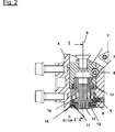
In der in
Im Inneren des Schieberelementes
Die Schwertspindel
Zum Einstellen des Schieberelementes und damit der exakten Position der Schneidplatte
Die Doppelgewindespindel
Durch Drehen der Schwertspindel
Wie insbesondere in
Weist das scheibenförmige Element
Ohne das Federelement
Durch die erfindungsgemäße Anordnung des Federelementes
BezugszeichenlisteLIST OF REFERENCE NUMBERS
- 11
- Zerspanungswerkzeugcutting tool
- 22
- Schneidplattecutting board
- 33
- Schieberelementslide element
- 44
- WerkzeuggrundkörperTool body
- 55
- Verdrehsicherungtwist
- 66
- Achseaxis
- 77
- Schieberbuchsedisc bushing
- 88th
- DoppelgewindespindelDouble threaded spindle
- 99
- GrundkörperbuchseBase socket
- 1010
- Schwertspindelsword spindle
- 1111
- Stegelementweb element
- 1212
- Skalenscheibedial
- 1313
- Federelementspring element
- 1414
- scheibenförmiger Abschnittdisc-shaped section
- 1515
- klingenförmiger Abschnittblade-shaped section
- 1616
- DruckstückPressure piece
ZITATE ENTHALTEN IN DER BESCHREIBUNG QUOTES INCLUDE IN THE DESCRIPTION
Diese Liste der vom Anmelder aufgeführten Dokumente wurde automatisiert erzeugt und ist ausschließlich zur besseren Information des Lesers aufgenommen. Die Liste ist nicht Bestandteil der deutschen Patent- bzw. Gebrauchsmusteranmeldung. Das DPMA übernimmt keinerlei Haftung für etwaige Fehler oder Auslassungen.This list of the documents listed by the applicant has been generated automatically and is included solely for the better information of the reader. The list is not part of the German patent or utility model application. The DPMA assumes no liability for any errors or omissions.
Zitierte PatentliteraturCited patent literature
- DE 102005045752 [0006] DE 102005045752 [0006]
Claims (9)
Priority Applications (7)
| Application Number | Priority Date | Filing Date | Title |
|---|---|---|---|
| DE102010002557A DE102010002557A1 (en) | 2010-03-03 | 2010-03-03 | Cutting tool with backlash-free fine adjustment |
| JP2012555358A JP2013521139A (en) | 2010-03-03 | 2011-02-18 | Machining tool with ultra fine adjustment without backlash |
| US13/581,828 US20130209188A1 (en) | 2010-03-03 | 2011-02-18 | Machining Tool Having Zero-Backlash Ultrafine Adjustment |
| PCT/EP2011/052424 WO2011107357A1 (en) | 2010-03-03 | 2011-02-18 | Machining tool having zero-backlash ultrafine adjustment |
| KR1020127022862A KR20130038191A (en) | 2010-03-03 | 2011-02-18 | Machining tool having zero-backlash ultrafine adjustment |
| EP11705508A EP2542367A1 (en) | 2010-03-03 | 2011-02-18 | Machining tool having zero-backlash ultrafine adjustment |
| CN2011800123010A CN103079734A (en) | 2010-03-03 | 2011-02-18 | Machining tool having zero-backlash ultrafine adjustment |
Applications Claiming Priority (1)
| Application Number | Priority Date | Filing Date | Title |
|---|---|---|---|
| DE102010002557A DE102010002557A1 (en) | 2010-03-03 | 2010-03-03 | Cutting tool with backlash-free fine adjustment |
Publications (1)
| Publication Number | Publication Date |
|---|---|
| DE102010002557A1 true DE102010002557A1 (en) | 2011-09-08 |
Family
ID=43983302
Family Applications (1)
| Application Number | Title | Priority Date | Filing Date |
|---|---|---|---|
| DE102010002557A Withdrawn DE102010002557A1 (en) | 2010-03-03 | 2010-03-03 | Cutting tool with backlash-free fine adjustment |
Country Status (7)
| Country | Link |
|---|---|
| US (1) | US20130209188A1 (en) |
| EP (1) | EP2542367A1 (en) |
| JP (1) | JP2013521139A (en) |
| KR (1) | KR20130038191A (en) |
| CN (1) | CN103079734A (en) |
| DE (1) | DE102010002557A1 (en) |
| WO (1) | WO2011107357A1 (en) |
Families Citing this family (5)
| Publication number | Priority date | Publication date | Assignee | Title |
|---|---|---|---|---|
| KR101337591B1 (en) * | 2012-05-07 | 2013-12-06 | (주) 테크노라이즈 | Use is convenient minute height adjusting device for fixing of tool |
| JP6251358B1 (en) * | 2016-11-14 | 2017-12-20 | 株式会社日研工作所 | Boring tools |
| DE102017213063A1 (en) * | 2017-07-28 | 2019-01-31 | Gühring KG | CUTTING TOOL WITH ONE SITE DEVICE |
| CN108500307A (en) * | 2018-04-23 | 2018-09-07 | 成都成林数控刀具有限公司 | A kind of Miniature adjustable double-blade boring cutter |
| WO2020239897A1 (en) | 2019-05-29 | 2020-12-03 | Big Kaiser Präzisionswerkzeuge Ag | Boring head with a mechanism for clamping a displaceable tool carrier |
Citations (6)
| Publication number | Priority date | Publication date | Assignee | Title |
|---|---|---|---|---|
| DE3446275C1 (en) * | 1984-12-19 | 1986-07-24 | Samson Ag, 6000 Frankfurt | Rotating drill head with an infeed device arranged between a connecting shank and a tool carrier |
| US5125773A (en) * | 1990-11-02 | 1992-06-30 | Kiyoshi Miyashita | Boring bar |
| JP2001121320A (en) * | 1999-10-21 | 2001-05-08 | Mitsubishi Materials Corp | Cutting tool |
| US6846136B2 (en) * | 2002-08-06 | 2005-01-25 | Velenite Inc. | Rotatable cutting tool |
| DE102005045752A1 (en) | 2005-09-23 | 2007-03-29 | Sandvik Intellectual Property Ab | Cutting tool with ultra-fine adjustment |
| DE102007041447B3 (en) * | 2007-08-31 | 2009-04-16 | Kieninger Gmbh | Fixing arrangement for cutting tool of boring bar, has cutting center support and supporting element with coactive contact surfaces, where cutting center support and supporting element are arranged one after another |
Family Cites Families (14)
| Publication number | Priority date | Publication date | Assignee | Title |
|---|---|---|---|---|
| US1697509A (en) * | 1924-02-20 | 1929-01-01 | Jr John M Marty | Expansible reamer |
| GB1071055A (en) * | 1963-09-11 | 1967-06-07 | Wickman Wimet Ltd | Adjustable tool for use with boring bars and other tool holders |
| US3323193A (en) * | 1965-12-16 | 1967-06-06 | Walter J Greenleaf Jr | Cutting tool cartridge insert |
| US3447403A (en) * | 1968-06-17 | 1969-06-03 | Allegheny Ludlum Steel | Adjustable boring unit |
| US3682561A (en) * | 1971-01-18 | 1972-08-08 | Raymond E Lemery | Cutter tooth mounting for fine wear adjustment |
| US3709625A (en) * | 1971-05-06 | 1973-01-09 | Ingersoll Milling Machine Co | Cutting tooth mounting for coarse and fine adjustment |
| US3741672A (en) * | 1971-07-29 | 1973-06-26 | N Hedberg | Adjustable tool holder |
| US3937587A (en) * | 1974-07-05 | 1976-02-10 | The Ingersoll Milling Machine Company | Adjustable cutter tooth mounting |
| US4428704A (en) * | 1980-07-28 | 1984-01-31 | Ex-Cell-O Corporation | Micro-adjusting cartridge for cutting tool |
| DE4330822A1 (en) * | 1993-09-13 | 1995-03-16 | Komet Stahlhalter Werkzeug | Tool head for use in machine tools |
| FR2747563B1 (en) * | 1996-04-17 | 1998-06-05 | Micro Mega Int Mfg Sa | HANDLE FOR ROTARY DENTAL INSTRUMENT |
| TWI357364B (en) * | 2005-04-26 | 2012-02-01 | Kaiser Heinz Ag | Boring tool |
| FI20050916A0 (en) * | 2005-09-14 | 2005-09-14 | Mandrel Oy | Arrangement in the cutting tool |
| US7753626B2 (en) * | 2007-01-18 | 2010-07-13 | Kennametal Inc. | Micro-adjustable differential screw assembly |
-
2010
- 2010-03-03 DE DE102010002557A patent/DE102010002557A1/en not_active Withdrawn
-
2011
- 2011-02-18 KR KR1020127022862A patent/KR20130038191A/en not_active Application Discontinuation
- 2011-02-18 WO PCT/EP2011/052424 patent/WO2011107357A1/en active Application Filing
- 2011-02-18 EP EP11705508A patent/EP2542367A1/en not_active Withdrawn
- 2011-02-18 JP JP2012555358A patent/JP2013521139A/en active Pending
- 2011-02-18 US US13/581,828 patent/US20130209188A1/en not_active Abandoned
- 2011-02-18 CN CN2011800123010A patent/CN103079734A/en active Pending
Patent Citations (6)
| Publication number | Priority date | Publication date | Assignee | Title |
|---|---|---|---|---|
| DE3446275C1 (en) * | 1984-12-19 | 1986-07-24 | Samson Ag, 6000 Frankfurt | Rotating drill head with an infeed device arranged between a connecting shank and a tool carrier |
| US5125773A (en) * | 1990-11-02 | 1992-06-30 | Kiyoshi Miyashita | Boring bar |
| JP2001121320A (en) * | 1999-10-21 | 2001-05-08 | Mitsubishi Materials Corp | Cutting tool |
| US6846136B2 (en) * | 2002-08-06 | 2005-01-25 | Velenite Inc. | Rotatable cutting tool |
| DE102005045752A1 (en) | 2005-09-23 | 2007-03-29 | Sandvik Intellectual Property Ab | Cutting tool with ultra-fine adjustment |
| DE102007041447B3 (en) * | 2007-08-31 | 2009-04-16 | Kieninger Gmbh | Fixing arrangement for cutting tool of boring bar, has cutting center support and supporting element with coactive contact surfaces, where cutting center support and supporting element are arranged one after another |
Also Published As
| Publication number | Publication date |
|---|---|
| JP2013521139A (en) | 2013-06-10 |
| WO2011107357A1 (en) | 2011-09-09 |
| EP2542367A1 (en) | 2013-01-09 |
| CN103079734A (en) | 2013-05-01 |
| KR20130038191A (en) | 2013-04-17 |
| US20130209188A1 (en) | 2013-08-15 |
Similar Documents
| Publication | Publication Date | Title |
|---|---|---|
| DE102018100054B4 (en) | Lockable torque wrench with a beep | |
| EP2398671B1 (en) | Fitting for a vehicle seat | |
| EP1767295A2 (en) | Cutting tool with fine positioning | |
| DE102010062414B4 (en) | Wobble joint fitting for an adjustment device of a motor vehicle seat, in particular for a backrest joint fitting | |
| DE102010002557A1 (en) | Cutting tool with backlash-free fine adjustment | |
| DE3407033A1 (en) | KEY | |
| DE3031216C2 (en) | Chuck for taps | |
| DE102009022051B3 (en) | Cutting tool is clamped on drive shaft by clamping device and has tool part that is connected with clamping device, where another tool part is adjustable in axial direction | |
| WO2010006965A2 (en) | Tool which can be axially adjusted | |
| WO2010026056A1 (en) | Machine tool with adjustable cutting plate | |
| EP2300184A1 (en) | Tool comprising a fastening unit | |
| DE102006043730B3 (en) | System pendulum device for chuck, has base element that is attachable to flanges of chuck by connection device, and pendulum element with clamping device having two replaceable clamping elements, which are adjustable and fixable | |
| DE102015017478B4 (en) | boring head | |
| DE202010011709U1 (en) | Device for mounting and dismounting a motor vehicle clutch | |
| DE10135354A1 (en) | disc brake | |
| DE3221158C2 (en) | Adjustable lock, especially for fittings | |
| DE102009044995A1 (en) | Cutting tool with replaceable cutting insert | |
| EP2337646B1 (en) | Internal broaching tool | |
| DE4139650C2 (en) | Fine boring tool | |
| DE102016210227A1 (en) | Actuator for a rear axle steering | |
| DE102019214040A1 (en) | END MILL AND METHOD OF MANUFACTURING THEREOF | |
| DE202015101365U1 (en) | chuck | |
| DE102019212220A1 (en) | Strain wave gear | |
| DE4143450C2 (en) | Fine boring tool, especially for through holes | |
| WO2019020786A1 (en) | Cutting tool |
Legal Events
| Date | Code | Title | Description |
|---|---|---|---|
| R012 | Request for examination validly filed | ||
| R119 | Application deemed withdrawn, or ip right lapsed, due to non-payment of renewal fee |