JP2013511008A - Pressure regulating valve seal, pressure regulating system and method - Google Patents
Pressure regulating valve seal, pressure regulating system and method Download PDFInfo
- Publication number
- JP2013511008A JP2013511008A JP2012538864A JP2012538864A JP2013511008A JP 2013511008 A JP2013511008 A JP 2013511008A JP 2012538864 A JP2012538864 A JP 2012538864A JP 2012538864 A JP2012538864 A JP 2012538864A JP 2013511008 A JP2013511008 A JP 2013511008A
- Authority
- JP
- Japan
- Prior art keywords
- pressure regulating
- regulating valve
- valve
- pin
- housing
- Prior art date
- Legal status (The legal status is an assumption and is not a legal conclusion. Google has not performed a legal analysis and makes no representation as to the accuracy of the status listed.)
- Pending
Links
Images


Classifications
-
- F—MECHANICAL ENGINEERING; LIGHTING; HEATING; WEAPONS; BLASTING
- F16—ENGINEERING ELEMENTS AND UNITS; GENERAL MEASURES FOR PRODUCING AND MAINTAINING EFFECTIVE FUNCTIONING OF MACHINES OR INSTALLATIONS; THERMAL INSULATION IN GENERAL
- F16K—VALVES; TAPS; COCKS; ACTUATING-FLOATS; DEVICES FOR VENTING OR AERATING
- F16K17/00—Safety valves; Equalising valves, e.g. pressure relief valves
- F16K17/02—Safety valves; Equalising valves, e.g. pressure relief valves opening on surplus pressure on one side; closing on insufficient pressure on one side
- F16K17/04—Safety valves; Equalising valves, e.g. pressure relief valves opening on surplus pressure on one side; closing on insufficient pressure on one side spring-loaded
- F16K17/06—Safety valves; Equalising valves, e.g. pressure relief valves opening on surplus pressure on one side; closing on insufficient pressure on one side spring-loaded with special arrangements for adjusting the opening pressure
-
- F—MECHANICAL ENGINEERING; LIGHTING; HEATING; WEAPONS; BLASTING
- F02—COMBUSTION ENGINES; HOT-GAS OR COMBUSTION-PRODUCT ENGINE PLANTS
- F02M—SUPPLYING COMBUSTION ENGINES IN GENERAL WITH COMBUSTIBLE MIXTURES OR CONSTITUENTS THEREOF
- F02M37/00—Apparatus or systems for feeding liquid fuel from storage containers to carburettors or fuel-injection apparatus; Arrangements for purifying liquid fuel specially adapted for, or arranged on, internal-combustion engines
- F02M37/0011—Constructional details; Manufacturing or assembly of elements of fuel systems; Materials therefor
- F02M37/0023—Valves in the fuel supply and return system
- F02M37/0029—Pressure regulator in the low pressure fuel system
-
- Y—GENERAL TAGGING OF NEW TECHNOLOGICAL DEVELOPMENTS; GENERAL TAGGING OF CROSS-SECTIONAL TECHNOLOGIES SPANNING OVER SEVERAL SECTIONS OF THE IPC; TECHNICAL SUBJECTS COVERED BY FORMER USPC CROSS-REFERENCE ART COLLECTIONS [XRACs] AND DIGESTS
- Y10—TECHNICAL SUBJECTS COVERED BY FORMER USPC
- Y10T—TECHNICAL SUBJECTS COVERED BY FORMER US CLASSIFICATION
- Y10T137/00—Fluid handling
- Y10T137/0318—Processes
- Y10T137/0396—Involving pressure control
Abstract
圧力調整バルブは、流体通路とその流体通路の開口部周辺に配置される平坦なシート(107)とを区画形成するハウジング(105)と吐出口とを備える。バルブが閉じたときにシート(107)に接触する立ち上がったエラストマーのエンボス(101)を備えたピン(110)は、ハウジング内において軸方向に配置される。ピン(110)は、エラストマーのエンボス(101)がそのシートに接触した状態を維持してバルブを閉じた状態を維持するとともにバルブの開弁圧を制御するように付勢される。圧力調整バルブのハウジング(105)を通過して外部へ流れる流体は、この付勢力のレベルを調節して制御される。このような方法で、流れが概して層状の流れとなり、流れの開始時にバルブが圧力ゲインを最小にとどめることで、バルブが開くときに流体の流れはシートを越えて平坦なシートとエンボスの間とを流れる。The pressure regulating valve includes a housing (105) and a discharge port that define a fluid passage and a flat sheet (107) disposed around the opening of the fluid passage. A pin (110) with raised elastomeric embossing (101) that contacts the seat (107) when the valve is closed is disposed axially within the housing. The pin (110) is biased to maintain the elastomeric embossing (101) in contact with its seat to maintain the valve closed and to control the valve opening pressure. The fluid flowing outside through the pressure regulating valve housing (105) is controlled by adjusting the level of this biasing force. In this way, the flow is generally laminar and the valve minimizes the pressure gain at the beginning of the flow so that when the valve is opened, the fluid flow is between the flat sheet and the embossment across the sheet. Flowing.
Description
本発明は、概略的に圧力リリーフおよび圧力調整のバルブに関し、特に圧力調整バルブ等において、流量増加に伴う圧力ゲインを最小限に抑えるバルブシールであり、具体的には、流量増加に伴う圧力の増加を最小にすることが、システムの性能の向上に望ましく、燃料噴射や他のシステムに用いて好適なものである。 The present invention generally relates to a pressure relief and pressure adjustment valve, and more particularly to a valve seal that minimizes a pressure gain accompanying an increase in flow rate in a pressure adjustment valve or the like. Minimizing the increase is desirable to improve system performance and is suitable for use in fuel injection and other systems.
内燃機関の燃料噴射システムは、一般的に圧力制御装置の形態を必要とし、これらは燃料噴射器における適切な燃料圧を維持するための、圧力調整もしくは圧力リリーフバルブのどちらかである。従来の燃料圧開放バルブと圧力調整装置は、圧力リリーフバルブにおいて、金属同士のシールを利用している。金属同士のシール要素は、近接するシール面の凹みに対して抵抗があり、結果として最小限の圧力降下で直接的な流路ができる。しかしながら、金属同士のシールは、2つのシール面が硬く、適合しておらず、不純物の混入による影響に対して非常に敏感で、高い漏出率になりやすい。この問題に対する1つの解決方法は、ゴムシールの圧力調整バルブを採用することである。このような燃料圧調整バルブはゴムのシール要素を備える。ゴムのシール要素は、立ち上がったボス部を有する金属シートと密に接触して保持され、立ち上がったボス部は、平面のゴム要素の表面に接触して押し下げる。そのような従来のバルブ設計では、環状の金属シール面は、相対的に厚く平坦なゴムパッドと接触してバルブシールに作用する。ゴムには相対的な軟質性と粘弾性という特性があるため、金属リングはゴム表面に永続的なくぼみを生じさせる。この表面の押し下げが、ゴムにおいて特有に「圧縮永久ひずみ」が起きる。バルブが開き始めると、流体の流れはゴムの表面変形によって形成された複雑な溝に沿うように形成させられ、その結果として圧力調整バルブが開き始めると入り組んだ流路が生じる。長く回旋状の流路は、初期のバルブ開放時における顕著な圧力降下を起こす。 Internal combustion engine fuel injection systems generally require the form of pressure control devices, which are either pressure regulation or pressure relief valves to maintain the proper fuel pressure in the fuel injector. Conventional fuel pressure release valves and pressure regulators use metal-to-metal seals in pressure relief valves. Metal-to-metal seal elements are resistant to indentations in adjacent seal surfaces, resulting in a direct flow path with minimal pressure drop. However, metal-to-metal seals are hard and incompatible with the two sealing surfaces, are very sensitive to the effects of contamination and tend to have a high leakage rate. One solution to this problem is to employ a rubber seal pressure regulating valve. Such a fuel pressure regulating valve includes a rubber sealing element. The rubber sealing element is held in intimate contact with the metal sheet having the raised boss portion, and the raised boss portion is pressed against the surface of the flat rubber element. In such conventional valve designs, the annular metal seal surface acts on the valve seal in contact with a relatively thick and flat rubber pad. Due to the relative softness and viscoelastic properties of rubber, metal rings cause permanent depressions on the rubber surface. This depression of the surface causes “compression set”, which is unique in rubber. When the valve begins to open, the fluid flow is formed along a complex groove formed by surface deformation of the rubber, resulting in an intricate flow path when the pressure regulating valve begins to open. The long convoluted flow path causes a significant pressure drop when the valve is initially opened.
金属同士でシールされた装置は、ゴムシールの圧力調整バルブよりも高価で、かつ高い漏出率を有する。漏出は、典型的に関連した車両を始動させる困難さが高まることに関係する。しかしながら、従来のゴムシールの圧力リリーフバルブと圧力調整装置は、大きな圧力降下と小さい直線的流量特性を有する。これらの傾向が、ゴムシールの圧力調整バルブの適用を制限している。 A device sealed with metal is more expensive than a rubber seal pressure regulating valve and has a high leakage rate. Leakage is typically associated with increased difficulty in starting the associated vehicle. However, conventional rubber seal pressure relief valves and pressure regulators have large pressure drops and small linear flow characteristics. These trends limit the application of rubber seal pressure regulating valves.
本発明は、圧力調整バルブにおける低い流量条件下での圧力降下を最小限にするシステムと方法に向けられる。 The present invention is directed to a system and method that minimizes pressure drop under low flow conditions in a pressure regulating valve.
本発明は、ゴムシールの圧力調整バルブにおけるシール要素の配置を逆にし、平坦な金属シートに接触するゴム部品に立ち上がったボス部を設けている。「圧縮永久ひずみ」に抵抗力がある金属シートは、平坦な表面を維持し、流動燃料の圧力降下を最小限にして直進する流路形成を可能にする。 In the present invention, the arrangement of the sealing element in the pressure regulating valve of the rubber seal is reversed, and the boss portion that rises on the rubber component that contacts the flat metal sheet is provided. A metal sheet that is resistant to “compression set” maintains a flat surface and allows straight flow path formation with minimal pressure drop of the flowing fuel.
本発明は、従来の金属同士の圧力調整バルブのシールと比較して圧力調整バルブが閉じるときの燃料漏出を減少させる。この漏出の減少は、車両がエンジンを止めている間に燃料圧を保持する燃料噴射システムの性能について有利である。 The present invention reduces fuel leakage when the pressure regulating valve closes compared to conventional metal-to-metal pressure regulating valve seals. This reduction in leakage is advantageous for the performance of the fuel injection system that maintains the fuel pressure while the vehicle shuts off the engine.
このように、本発明の種々の実施形態に従って、燃料圧調整バルブのような圧力調整バルブは、流体通路を区画形成したハウジングと、流体通路の開口部の周囲に配置される平坦なシートとを備える。そのハウジングはまた、好ましくは吐出口を備える。ピンは、好ましくは、ハウジング内に軸方向に配置される。このピンは、好ましくは、バルブが閉じるときにシートに接触する立ち上がったエラストマーのエンボスを備える。例えば、そのピンには立ち上がった環状部を備え、その環状部を覆ってエラストマーのエンボスが形成されてもよい。このオーバーモールド成形されたエラストマーは、約0.002インチ厚から約0.020インチ厚の範囲でもよく、好ましくは約0.007インチ厚である。そのエラストマーは、システムにおいて用いられる流体に曝された際の化学的安定性に応じて選択されたフッ素エラストマー、ニトリル等でもよい。そのピンは、好ましくは、圧縮ばね力を付与することにより付勢され、エラストマーのエンボスをシートに接触した状態を維持して、バルブを閉じた状態を維持するとともにバルブの開弁圧を制御する。この付勢力は、好ましくは調節可能で、ハウジング内に配置されてピンに接触するばねと、ハウジング内に配置されてばねの付勢力を接触して調節する調節ねじにより与えられてもよい。そのばねは、コイルばねであってもよいし、エラストマーばね、片持ちばね構造、円錐コイルばね等の他の類似の付勢部材であってもよい。 Thus, according to various embodiments of the present invention, a pressure regulating valve, such as a fuel pressure regulating valve, includes a housing that defines a fluid passage and a flat seat that is disposed around the opening of the fluid passage. Prepare. The housing also preferably includes a discharge port. The pins are preferably arranged axially within the housing. The pin preferably comprises a raised elastomeric embossment that contacts the seat when the valve is closed. For example, the pin may be provided with a raised annular portion, and an elastomer emboss may be formed covering the annular portion. The overmolded elastomer may range from about 0.002 inches thick to about 0.020 inches thick, and is preferably about 0.007 inches thick. The elastomer may be a fluoroelastomer, nitrile or the like selected according to chemical stability when exposed to the fluid used in the system. The pin is preferably biased by applying a compression spring force to maintain the elastomeric embossing in contact with the seat to maintain the valve closed and control the valve opening pressure. . This biasing force is preferably adjustable and may be provided by a spring disposed within the housing that contacts the pin and an adjustment screw disposed within the housing that contacts and adjusts the biasing force of the spring. The spring may be a coil spring or other similar biasing member such as an elastomer spring, a cantilever spring structure, or a conical coil spring.
操作時において、圧力調整バルブのこのような実施形態では、流路の周囲に形成された平坦なシートで1つの流路を形成する。例えば、ピンによって区画形成された環状部をエラストマー材料でオーバーモールド成形することによって、ピンに形成された立ち上がったエラストマーのエンボスは、ハウジング内の軸方向に収容される。ピンは、好ましくは、バルブが閉じるときにエンボスがシートに接触して付勢され、圧力調整バルブハウジングを通りハウジング外へ流れる流体の流れは、付勢力のレベルを通じて制御される。バルブが開くと、流体の流れは平坦なシートを越えてシートとエンボスとの間を流れ、流れが流量特性に対してほぼ直線状となる。 In operation, in such an embodiment of the pressure regulating valve, one flow path is formed by a flat sheet formed around the flow path. For example, by overmolding an annular portion defined by a pin with an elastomeric material, the raised elastomeric emboss formed on the pin is accommodated axially within the housing. The pin is preferably energized with the embossing contacting the seat when the valve is closed, and the flow of fluid through the pressure regulating valve housing and out of the housing is controlled through the level of the energizing force. When the valve is opened, the fluid flow passes over the flat sheet between the sheet and the emboss, and the flow is substantially linear with respect to the flow characteristics.
本発明の圧力調整バルブの実施形態に従って、油圧式機構または電気的作動機構が、自動的またはプログラムされたロジックによって管理されたレベルの付勢力を付与するために使用されてもよい。同様に、幾つかの実施形態に従って、油圧式または電気的作動機構が、自動的またはプログラムされたロジックによって付勢ばね等の張力を変化させるために採用されてもよい。 In accordance with embodiments of the pressure regulating valve of the present invention, a hydraulic or electrically actuated mechanism may be used to apply a level of biasing force that is managed automatically or by programmed logic. Similarly, in accordance with some embodiments, a hydraulic or electrical actuation mechanism may be employed to change the tension of a biasing spring or the like automatically or by programmed logic.
流れの圧力降下に関して、本発明は、配置された燃料噴射システム等に対して、圧力調整バルブが動作するときに圧力降下の減少と、圧力調整バルブが動作しているときの流体の流量の範囲におけるより直線的な流量対圧力降下の関係とをもたらす。圧力降下の減少により、燃料噴射装置がより低い圧力の変化にさらされたときに、燃料噴射装置の性能の確実さが向上する。この直線的関係は、圧力降下の予測可能性を高めることにより、燃料噴射制御システムの効率を改善する。 With respect to flow pressure drop, the present invention relates to a reduced fuel pressure drop when the pressure regulating valve is operating and a range of fluid flow rates when the pressure regulating valve is operating, such as for a deployed fuel injection system. Resulting in a more linear flow rate versus pressure drop relationship. The reduced pressure drop increases the certainty of the fuel injector performance when the fuel injector is subjected to lower pressure changes. This linear relationship improves the efficiency of the fuel injection control system by increasing the predictability of the pressure drop.
本発明のバルブによる圧力降下の減少は、幾つかの利点をもたらす。第一に、圧力降下そのものが利点である。第二に、流量が増加したときに流路は基本的に変化しないので、流体の圧力降下の変化率が一定になり、流量対圧力降下の関係の直線性を改善する。そして最後に、この圧力降下は、バルブの経年による長時間経過や個々のバルブ間のいずれかによってゴムの性質が変わるときにも変化しない。 The reduction in pressure drop with the valve of the present invention provides several advantages. First, the pressure drop itself is an advantage. Second, since the flow path basically does not change when the flow rate increases, the rate of change of the pressure drop of the fluid becomes constant, improving the linearity of the flow rate versus pressure drop relationship. And finally, this pressure drop does not change when the rubber properties change due to either the long-term passage of the valve or between individual valves.
前述の事項は、後述する発明の詳細な説明がよりよく理解されるために、本発明の特徴と技術的な利点について概略的に述べた。本発明の特徴と利点は下に記述され、それらは本発明の特許請求の範囲の主題を構成する。本発明と同じ目的を達成するために、他の構造を設計するか、あるいは変更するための基礎として、開示された着想と特定の実施形態が、容易に使用されることは当業者によって理解されるべきである。また、このような均等の構造が添付の特許請求の範囲に記載された発明の意図や範囲から逸脱しないことは、当業者によって理解されるべきである。その構成と操作方法の双方について、本発明の特徴であると信じられる新規な特徴が、さらなる目的および利点とともに、添付の図面と関連させて考慮に入れたときに下記の説明からより理解されるであろう。各図面は、例示および説明の目的にのみ提供されており、本発明の限定した解釈を意図するものではないことを、明らかに理解されるべきである。 The foregoing has outlined rather broadly the features and technical advantages of the present invention in order that the detailed description of the invention that follows may be better understood. The features and advantages of the invention are described below, which form the subject of the claims of the invention. It will be appreciated by those skilled in the art that the disclosed concepts and specific embodiments can be readily used as a basis for designing or modifying other structures to achieve the same purpose as the present invention. Should be. It should also be understood by those skilled in the art that such equivalent structures do not depart from the spirit and scope of the invention as set forth in the appended claims. The novel features believed to be characteristic of the invention, both as to its construction and method of operation, together with further objects and advantages, will be better understood from the following description when considered in conjunction with the accompanying drawings. Will. It should be clearly understood that the drawings are provided for purposes of illustration and description only and are not intended as a limited interpretation of the invention.
この明細書に組み込まれ、その部分を構成する添付の図面は、同じ番号は同じ部品を示しており、詳細な説明とともに本発明の実施形態を図示し、発明の本質を説明するために役立つ。図面において、 The accompanying drawings, which are incorporated in and constitute a part of this specification, illustrate the same parts with the same numbers, illustrate embodiments of the invention with detailed description, and serve to explain the essence of the invention. In the drawing
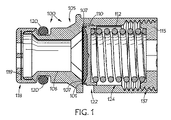
図1は、本願発明に従ったシール101を採用した圧力調整バルブ100の一実施形態の部分的に破断された概略断面図である。燃料圧力調整バルブ100は、主として、燃料通路106とシート107を区画形成しているハウジング105から構成される。ピン110は、ハウジング105内に配置される。ピン110は、バルブ100が閉じたときにシート107に接触するシールとして機能する立ち上がったエラストマーのエンボス101を備える。ハウジング内に配置されたばね112は、ピン110を付勢してゴムのエンボス101をシート107に接触させた状態を維持し、流体通路106のようなピン110と反対側の燃料圧がばね112の張力に打ち勝つまでバルブ100を閉じた状態に維持する。ハウジング105内に配置された調節ねじ115あるいは同様の機構が、ばね112によって供される付勢力を調節するために使用される。図1に示される実施形態はまた、入口フィルタ118を採用し、フィルタ118は、バルブハウジング105にスナップ止めされたナイロン樹脂製のハウジング内に保持されたナイロンメッシュのスクリーン119であってもよい。このようなフィルタスクリーンは、一般的に20〜50ミクロンのメッシュの穴を有する。Oリング120が、バルブとその取付け部との間のシールとなるためにハウジング105に外嵌されてもよく、バルブとその取付け部は、燃料タンクもしくは燃料システム内の他の場所のいずれかにおいて、燃料ポンプ本体、または他の燃料システムの機構であってもよい。そのOリングは、一般的には、フッ素エラストマー(FKM)ゴム製でありうるが、取り扱われている燃料に適合したいかなるゴムでも使用されうる。
FIG. 1 is a partially cutaway schematic cross-sectional view of one embodiment of a
ハウジング本体105は、好ましくは、燃料通路106のような、フィルタ118とシール101との間およびシール101から吐出口122を通る流路を備える。シール101より上のハウジングのボア124は、バルブピン110を作用的に収容し、バルブばね112の長さを制限する。好ましくは、ピン100は、本体105のボア124の中に軸方向に収容される。ハウジング105は、ピン110のシール101に協働的に接触するシールシート107を区画形成する。ハウジング105は真鍮製であってもよいし、選択的にニッケル等によりメッキされてもよい。他方において、ほとんどのいかなる非腐食性の金属あるいは腐食防止コーティングされた他の金属がハウジング105に採用可能である。代替的に、湿気や燃料に耐性のあるプラスチックを用いたプラスチック構造が用いられてもよい。
The
図2は、シーリング環状部230の上にオーバーモールド成形されたゴムシール101を表す概略円筒形のピン110の一実施形態の、拡大されたより詳細な部分的に破断された概略断面図である。オーバーモールド成形されたシール101は、環状部230を越えて、フランジ235の底部の上まで拡張してもよい。フランジ235は、ボア124内にピン110を整列させる。ピン110はまた、好ましくはばね112に係合し、また、ばね112とともにピン110を整列させるために概略円形状の凹部237を区画形成する。代替的に、ピン110は、ばね112と係合しピン110とともにばね112を整列させるためにピン110から突出したボス部あるいは他の構造を形成してもよい。シーリング環状部230を覆うオーバーモールド成形されたゴムシール101の相対的な薄さは、本バルブに反復性と耐久性を与える。環状部230の相対的に浅い深さのために、この性能の反復性と耐久性をより助長することができる。好ましくは、環状部230のシール101の厚さは、シール101の形状およびゴムの膨潤による膨張を制限できる程度まで充分に薄い。好ましくは、シール101の形状は環状部230の補強金属によって維持される。
FIG. 2 is an enlarged, more detailed, partially broken schematic cross-sectional view of one embodiment of a generally
ピン110はニッケルメッキした真鍮製でもよく、耐腐食性のあるいかなる金属から製造されてもよいし、コーティングされてもよい。代替的に、ピン110は、プラスチックから製造されてもよい。シール101は、FKMより製造されるが、取り扱われている燃料に適した他の配合ゴムが使用されもよい。
The
図1を参照すると、ばね112は、ピン110上部と調節ねじ115の間に圧縮した状態に保たれる。ばねはステンレス鋼であってもよいし、取り扱われている燃料に関して適当な耐腐食性のある他の材料を使用してもよい。さらに、ばねは図1に図示するようなコイルばねであってもよいが、ある種の弾性構造、あるいは片持ちもしくは円錐ばねであってもよい。バルブ開弁圧は、正確なバルブ100の開弁圧を提供するため、正確なばね力がピン110に付与されてシール101より下において所望の流体圧に釣り合うまで、本体105内で区画形成されたねじ山137におけるねじ115の軸方向位置を調節することによって較正され、その後ねじ115はその位置で固定される。図1の実施形態に示されるように、ハウジング105と調節ねじ115の間においてねじ山をロックするためにアプセッタ型等が使用されてもよい。他方で、機械的なロックもしくは調節ピンのような他の部品が使われてもよい。調節ねじはニッケルコーティングされた真鍮製であってもよい。他方で、耐腐食コーティングあるいはメッキされた、ほとんどのいかなる非腐食性の金属もしくは他の金属がねじ115を製造する際に使用されうる。湿度と燃料に耐性のあるプラスチックを用いたプラスチック構造もまた、使用されてもよい。ねじ山とは別の調節手段もまた、製造や組み立て工程の材料に合うものが使用されてもよい。
Referring to FIG. 1, the
図3に注目すると、本発明のバルブ内の構成要素の配置は、先行技術とは対照的に実質的に異なる流路を形成する。図3は、バルブ100が開いた状態を示し、その結果として矢印で表示するような直線形の流線型の流れが生じる。本発明の構成では、ハウジングによって区画形成されたシート107の金属表面は平坦であり、上部に立ち上がった環状のリングは、好ましくは金属補強されたエンボス230に成型されたゴム101の薄い層により形成される。このような実施形態においては、長時間経過によりゴムに起こる変位や膨潤によって、バルブ内の流路が変化することがない。好ましくは、ゴムのエンボスの薄い部分の厚さは、形状の膨張を制限し、これは補強金具によって維持される。バルブが開き始めると、流体の流れは方向が変わったり、回旋状の通路によって拘束されることなく、ハウジングシートの金属表面と平行に直線状になる。この結果は、流れの開始時における圧力降下の減少である。
Referring to FIG. 3, the arrangement of components within the valve of the present invention forms a substantially different flow path as opposed to the prior art. FIG. 3 shows a state in which the
流れに対する圧力降下に関して、本発明は、圧力調整バルブが動作するときに圧力降下の減少と、圧力調整バルブが動作しているときの流体の流量の範囲におけるより直線的な流量対圧力降下の関係とを、燃料噴射装置に与える。圧力降下の減少により、燃料噴射装置が、より低い圧力の変化にさらされたときに、燃料噴射装置の性能の確実さが向上する。この直線的関係は、圧力降下の予測可能性を高めることより、燃料噴射制御システムの効率を改善する。 With respect to pressure drop over flow, the present invention provides a relationship between reduced pressure drop when the pressure regulating valve is operating and a more linear flow rate versus pressure drop in the range of fluid flow rates when the pressure regulating valve is operating. To the fuel injector. The reduced pressure drop increases the certainty of the fuel injector performance when the fuel injector is exposed to lower pressure changes. This linear relationship improves the efficiency of the fuel injection control system by increasing the predictability of the pressure drop.
圧力調整バルブの幾つかの実施形態では、図4に図示されるように、付勢力は、ばね等以外の機構(412)によって付与されてもよいし、および/また、図5に図示されるように、手動調節ねじ以外の機構(514)によって調節されてもよい。 In some embodiments of the pressure regulating valve, as shown in FIG. 4, the biasing force may be applied by a mechanism (412) other than a spring and / or illustrated in FIG. As such, it may be adjusted by a mechanism (514) other than a manual adjustment screw.
例えば、図4は、油圧式付勢機構の実施例412を採用した本発明の調整バルブの実施形態400の部分破断図を示す。図示された油圧式付勢機構412は、近くに(あるいは離れた所に)設置された機構412に流体圧を与える油圧(あるいは空気圧の)バルブのようなものによって、その場所で制御されてもよい。この制御バルブは、また燃料噴射システムにおける車両エンジン制御モジュール(ECM)等によって制御されてもよいし、あるいは、バルブ400を採用する他のシステムにおける同様の制御機構によって制御されてもよい。油圧(補助)シリンダ等の形態をとる機構412は、プッシュロッド415を介してピン110を付勢してゴムのエンボス101をシート107に接触させた状態を維持し、ピン110と反対側の燃料圧がシリンダ412によって付与される圧力に打ち勝つまでバルブ400を閉じた状態に維持する。代替的に、機構412と同様の油圧または空気圧の機構が、圧力調整バルブの実施形態において、ばね(112)の張力を調節するために使用されてもよい(置き換えるのではなく)。
For example, FIG. 4 shows a partial cutaway view of a regulator valve embodiment 400 of the present invention employing a hydraulic biasing mechanism embodiment 412. The illustrated hydraulic biasing mechanism 412 may be controlled in place by something like a hydraulic (or pneumatic) valve that provides fluid pressure to a mechanism 412 located nearby (or remotely). Good. This control valve may also be controlled by a vehicle engine control module (ECM) or the like in the fuel injection system, or may be controlled by a similar control mechanism in other systems that employ the valve 400. The mechanism 412, which takes the form of a hydraulic (auxiliary) cylinder or the like, biases the
他の例として、図5は、電子的に作動する付勢調節機構の実施例515を採用した本発明の調整バルブの実施形態500の部分破断図を示す。バルブ500において、ばね112によって及ぼされる付勢力は、図5において517として概略的に示された電動ステッピングモータ等によって調節あるいは調整される。図示された実施例では、ステッピングモータ517は、螺旋軸515を回転させ、ばね112の張力を調節し、そして延いては付勢ばね112がピン110に力を付与し、ピン110と反対側の燃料圧がばね112に付与された張力に打ち勝つまでゴムのエンボス101をシート107に接触させた状態を維持し、バルブ100を閉じた状態に維持する。代替的に、図示されているようなステッピングモータと螺旋軸ではなく、ソレノイド等がばね112における付勢を調節するために使用されてもよい。
As another example, FIG. 5 shows a partial cutaway view of a regulating
油圧を付与するためのこれらあるいは他の機構が、ピン110を付勢するため、および/または、これらあるいは他の電子機構で、ピン110に付勢された付勢力を調節するために、相互に交換できるように使用してもよい。とにかく、このような実施形態は、例えば、環境上の、排気ガスの、もしくは出力の最適化のための付加された高度なエンジン制御機能をもたらすために燃料噴射装置に使われているように自動的もしくはプログラムされたロジックに従って付勢力を変化させることができる。
These or other mechanisms for applying hydraulic pressure may be mutually coupled to bias the
本発明およびその利点を説明してきたが、それは種々の変更、置換および改変が、添付の特許請求の範囲によって定義されているような、本発明の意図や範囲から逸脱することなく、ここに可能であることを理解すべきである。さらに本出願の範囲は、明細書中に記載されているプロセス、機械、製造、組成物、手段、方法そして手順の特定の実施形態に限定されることを意図するものでない。当業者は、本発明の開示から容易に理解するであろうから、ここに記載された対応する実施形態と実質的に同一の機能を実現する、もしくは実質的に同じ結果を達成する現存のもしくは後に開発されるプロセス、機械、製造、組成物、手段、方法そして手順は、本発明によって利用できるであろう。したがって、添付の特許請求の範囲は、それらの範囲内でそのようなプロセス、機械、製造、組成物、手段、方法そして手順を含むことを意図している。 Having described the invention and its advantages, it will be understood that various changes, substitutions and modifications may be made herein without departing from the spirit and scope of the invention as defined by the appended claims. Should be understood. Furthermore, the scope of this application is not intended to be limited to the specific embodiments of the processes, machines, manufacture, compositions, means, methods and procedures described in the specification. Those of ordinary skill in the art will readily appreciate from the disclosure of the present invention, so that an existing or achieving substantially the same function or achieving substantially the same results as the corresponding embodiments described herein. Later developed processes, machines, manufacture, compositions, means, methods and procedures may be utilized by the present invention. Accordingly, the appended claims are intended to include within their scope such processes, machines, manufacture, compositions of matter, means, methods, or procedures.
Claims (29)
前記ハウジング内において軸方向に配置されたピンとを備え、前記ピンはバルブが閉じたときに前記シートに接触する立ち上がったエラストマーのエンボスを有し、
前記ピンに付勢力を与え、前記エラストマーのエンボスを前記シートに接触させた状態を維持して、前記バルブを閉じた状態に維持するとともに前記バルブの開弁圧を制御するための付勢手段と、
前記付勢力を調節する手段と
を備えた圧力調整バルブ。 A housing that internally defines a fluid passage and a flat sheet disposed around the opening of the fluid passage;
An axially disposed pin within the housing, the pin having a raised elastomeric embossment that contacts the seat when the valve is closed;
An urging means for applying an urging force to the pin and maintaining the state in which the elastomer emboss is in contact with the seat to maintain the valve in a closed state and to control a valve opening pressure of the valve; ,
A pressure adjusting valve comprising: means for adjusting the biasing force.
前記ハウジング内において前記流路の周囲に平坦なシートを区画形成し、
ピンに立ち上がったエラストマーのエンボスを区画形成し、
前記ハウジング内に前記ピンを軸方向に収容し、
前記バルブが閉じるときに前記エンボスが前記シートに接触するように前記ピンに付勢力を与え、
前記付勢力のレベルに基づいて前記圧力調整バルブのハウジングを通過して外部へ流れる流体の流れを制御し、前記バルブが開くときには前記流体が前記平坦なシートを越えて前記平坦なシートと前記エンボスの間とを流れる方法。 A flow path is defined in the housing of the pressure adjustment valve,
A flat sheet is defined around the flow path in the housing,
Compartment formation of the embossed elastomer that stood up on the pin,
Housing the pin in the housing in the axial direction;
Energizing the pin so that the embossment contacts the seat when the valve is closed,
Based on the level of the biasing force, the flow of the fluid flowing through the pressure regulating valve housing to the outside is controlled, and when the valve is opened, the fluid passes over the flat sheet and the embossed flat sheet. To flow between.
Applications Claiming Priority (3)
| Application Number | Priority Date | Filing Date | Title |
|---|---|---|---|
| US12/590,696 | 2009-11-12 | ||
| US12/590,696 US9328836B2 (en) | 2009-11-12 | 2009-11-12 | Pressure regulator valve seals, systems and methods |
| PCT/US2010/055633 WO2011059893A1 (en) | 2009-11-12 | 2010-11-05 | Pressure regulator valve seals, systems and methods |
Publications (1)
| Publication Number | Publication Date |
|---|---|
| JP2013511008A true JP2013511008A (en) | 2013-03-28 |
Family
ID=43617951
Family Applications (1)
| Application Number | Title | Priority Date | Filing Date |
|---|---|---|---|
| JP2012538864A Pending JP2013511008A (en) | 2009-11-12 | 2010-11-05 | Pressure regulating valve seal, pressure regulating system and method |
Country Status (10)
| Country | Link |
|---|---|
| US (1) | US9328836B2 (en) |
| EP (1) | EP2499405B1 (en) |
| JP (1) | JP2013511008A (en) |
| KR (1) | KR20120091355A (en) |
| CN (1) | CN102597586A (en) |
| BR (1) | BR112012009280A2 (en) |
| CA (1) | CA2777385A1 (en) |
| IN (1) | IN2012DN03149A (en) |
| MX (1) | MX2012004756A (en) |
| WO (1) | WO2011059893A1 (en) |
Cited By (2)
| Publication number | Priority date | Publication date | Assignee | Title |
|---|---|---|---|---|
| JP2015040474A (en) * | 2013-08-20 | 2015-03-02 | 三菱電機株式会社 | Fuel supply device |
| DE102016122781A1 (en) | 2015-11-30 | 2017-06-01 | Aisan Kogyo Kabushiki Kaisha | Pressure control valve |
Families Citing this family (20)
| Publication number | Priority date | Publication date | Assignee | Title |
|---|---|---|---|---|
| US8210156B2 (en) * | 2009-07-01 | 2012-07-03 | Ford Global Technologies, Llc | Fuel system with electrically-controllable mechanical pressure regulator |
| US9328836B2 (en) * | 2009-11-12 | 2016-05-03 | Schrader Electronics Ltd. | Pressure regulator valve seals, systems and methods |
| EP2597034B1 (en) * | 2011-11-28 | 2015-11-04 | AIRBUS HELICOPTERS DEUTSCHLAND GmbH | Counterbalanced control stick system |
| JP6190580B2 (en) * | 2012-09-13 | 2017-08-30 | エドワーズ株式会社 | Rotary part of vacuum pump and vacuum pump |
| BE1022252B1 (en) * | 2013-05-14 | 2016-03-04 | Atlas Copco Airpower, Naamloze Vennootschap | MINIMUM PRESSURE VALVE |
| WO2014183173A1 (en) * | 2013-05-14 | 2014-11-20 | Atlas Copco Airpower, Naamloze Vennootschap | Minimum pressure valve |
| DE202015106096U1 (en) * | 2015-11-11 | 2016-02-19 | Holger Blum | Pressure maintenance and control valve |
| DE202015106097U1 (en) * | 2015-11-11 | 2016-02-01 | Holger Blum | Conveyor for a vacuum distillation plant |
| DE202015106101U1 (en) * | 2015-11-11 | 2016-02-01 | Holger Blum | metering |
| US10080332B1 (en) * | 2016-07-29 | 2018-09-25 | Mjnn, Llc | Self-sealing dripper apparatus |
| CN109952458B (en) * | 2016-09-21 | 2020-10-23 | 克诺尔商用车制动系统有限公司 | Minimum pressure valve for a screw compressor of a vehicle, in particular a commercial vehicle |
| CN106297913B (en) * | 2016-10-20 | 2023-09-15 | 中国船舶集团有限公司第七一八研究所 | Sealing structure capable of being automatically opened |
| CN107044369A (en) * | 2017-04-21 | 2017-08-15 | 上海中船三井造船柴油机有限公司 | Marine low speed diesel engine fuel oil supply system with pressure limiting and cushioning effect |
| CN107990032A (en) * | 2017-11-20 | 2018-05-04 | 余庆敏 | A kind of adjustable gas constant pressure valve |
| US10400911B2 (en) * | 2017-11-30 | 2019-09-03 | Sensata Technologies, Inc. | In-line fluid pressure regulator |
| AT16152U1 (en) * | 2018-03-01 | 2019-02-15 | Ing Andreas Zieger Dipl | Sealing system for valve |
| KR102195000B1 (en) * | 2019-04-30 | 2020-12-24 | 한국콘트롤공업 주식회사 | Relief Valve |
| CN113124158B (en) * | 2019-12-30 | 2022-04-22 | 中兴通讯股份有限公司 | Sealing assembly, shell and terminal equipment |
| KR102291256B1 (en) * | 2020-04-06 | 2021-08-20 | 주식회사 코아비스 | Fuel pump |
| KR20220125866A (en) | 2021-03-04 | 2022-09-15 | 삼성전자주식회사 | Vacuum valve and apparatus for fabricating semiconductor having the same |
Citations (12)
| Publication number | Priority date | Publication date | Assignee | Title |
|---|---|---|---|---|
| JPS496232U (en) * | 1972-04-18 | 1974-01-19 | ||
| JPS5020261Y1 (en) * | 1969-11-20 | 1975-06-19 | ||
| JPS5986768A (en) * | 1982-08-19 | 1984-05-19 | スペリー ウィッカース ツアイグニーデルラッツングデル スペリー ゲーエムベーハー | Safety valve device |
| JPH01122567U (en) * | 1988-02-15 | 1989-08-21 | ||
| JPH0332258U (en) * | 1989-08-08 | 1991-03-28 | ||
| JPH0577665U (en) * | 1992-03-19 | 1993-10-22 | 高雄 山根 | valve |
| JP2000028010A (en) * | 1998-07-14 | 2000-01-25 | Nok Corp | Valve device |
| JP2001082271A (en) * | 1999-08-05 | 2001-03-27 | Robert Bosch Gmbh | Pressure control valve |
| JP2001324246A (en) * | 2000-05-12 | 2001-11-22 | Zexel Valeo Climate Control Corp | Expansion valve and freezing cycle using it |
| JP2006152011A (en) * | 2004-11-25 | 2006-06-15 | Fujikura Rubber Ltd | Surface-treating composition, rubber surface-treating method, and manufacturing method of relief valve |
| JP2007026056A (en) * | 2005-07-15 | 2007-02-01 | Toho Seisakusho:Kk | Fluid pressure adjusting device |
| JP2008138732A (en) * | 2006-11-30 | 2008-06-19 | Piolax Inc | Relief valve |
Family Cites Families (16)
| Publication number | Priority date | Publication date | Assignee | Title |
|---|---|---|---|---|
| US2820474A (en) * | 1954-09-10 | 1958-01-21 | Anderson Greenwood & Co | Relief valve with high-pressure seal |
| US3438391A (en) * | 1964-01-13 | 1969-04-15 | Superior Valve & Fittings Co | Check valves having plastic sealing member |
| GB1371514A (en) | 1972-06-13 | 1974-10-23 | Alumasc Ltd | Safety relief valve for example for beverage-dispensing pressure- gas systems |
| JPH01122567A (en) | 1987-11-06 | 1989-05-15 | Japan Synthetic Rubber Co Ltd | Manufacture of solid electrolyte sheet |
| US5113900A (en) | 1991-01-30 | 1992-05-19 | Bridge Products, Inc. | Check valve with quick lock attachment feature |
| DE19913805A1 (en) | 1999-03-26 | 2000-04-20 | Bosch Gmbh Robert | Pressure limitation and safety valve for fuel feed pumps has valve body formed by plate of elastomer material to give short construction length |
| US6068022A (en) * | 1999-08-25 | 2000-05-30 | Schrader-Bridgeport International, Inc. | Jet pump with improved control valve and pressure relief valve therefore |
| CN2403966Y (en) * | 2000-01-05 | 2000-11-01 | 熊磊 | Non-return valve |
| US6311716B1 (en) * | 2000-09-05 | 2001-11-06 | John Blue Company | Fluid flow divider |
| DE10148960A1 (en) | 2000-10-06 | 2002-04-11 | Luk Fahrzeug Hydraulik | Pressure relief valve has cylindrical valve component and on side facing sealing seat has suitable recess by means of which insert with base element for elastomer coating is fitted |
| US6543745B1 (en) * | 2001-10-09 | 2003-04-08 | Halkey-Roberts Corporation | Male luer valve |
| US20030217770A1 (en) * | 2002-05-24 | 2003-11-27 | Schultz Jeffrey A. | Combination thermal and pressure relief valve |
| US7059582B2 (en) * | 2003-12-01 | 2006-06-13 | Societe Bic | Fuel cell supply having fuel compatible materials |
| CN101749215B (en) | 2004-11-12 | 2012-02-15 | Lg电子株式会社 | Discharge valve and valve assembly of reciprocating compressor having the same |
| JP2008075827A (en) * | 2006-09-25 | 2008-04-03 | Denso Corp | Fluid control valve |
| US9328836B2 (en) * | 2009-11-12 | 2016-05-03 | Schrader Electronics Ltd. | Pressure regulator valve seals, systems and methods |
-
2009
- 2009-11-12 US US12/590,696 patent/US9328836B2/en active Active
-
2010
- 2010-11-05 MX MX2012004756A patent/MX2012004756A/en not_active Application Discontinuation
- 2010-11-05 EP EP10779873.8A patent/EP2499405B1/en not_active Not-in-force
- 2010-11-05 CN CN2010800510409A patent/CN102597586A/en active Pending
- 2010-11-05 KR KR20127015055A patent/KR20120091355A/en not_active IP Right Cessation
- 2010-11-05 IN IN3149DEN2012 patent/IN2012DN03149A/en unknown
- 2010-11-05 WO PCT/US2010/055633 patent/WO2011059893A1/en active Application Filing
- 2010-11-05 CA CA 2777385 patent/CA2777385A1/en not_active Abandoned
- 2010-11-05 JP JP2012538864A patent/JP2013511008A/en active Pending
- 2010-11-05 BR BR112012009280A patent/BR112012009280A2/en not_active IP Right Cessation
Patent Citations (12)
| Publication number | Priority date | Publication date | Assignee | Title |
|---|---|---|---|---|
| JPS5020261Y1 (en) * | 1969-11-20 | 1975-06-19 | ||
| JPS496232U (en) * | 1972-04-18 | 1974-01-19 | ||
| JPS5986768A (en) * | 1982-08-19 | 1984-05-19 | スペリー ウィッカース ツアイグニーデルラッツングデル スペリー ゲーエムベーハー | Safety valve device |
| JPH01122567U (en) * | 1988-02-15 | 1989-08-21 | ||
| JPH0332258U (en) * | 1989-08-08 | 1991-03-28 | ||
| JPH0577665U (en) * | 1992-03-19 | 1993-10-22 | 高雄 山根 | valve |
| JP2000028010A (en) * | 1998-07-14 | 2000-01-25 | Nok Corp | Valve device |
| JP2001082271A (en) * | 1999-08-05 | 2001-03-27 | Robert Bosch Gmbh | Pressure control valve |
| JP2001324246A (en) * | 2000-05-12 | 2001-11-22 | Zexel Valeo Climate Control Corp | Expansion valve and freezing cycle using it |
| JP2006152011A (en) * | 2004-11-25 | 2006-06-15 | Fujikura Rubber Ltd | Surface-treating composition, rubber surface-treating method, and manufacturing method of relief valve |
| JP2007026056A (en) * | 2005-07-15 | 2007-02-01 | Toho Seisakusho:Kk | Fluid pressure adjusting device |
| JP2008138732A (en) * | 2006-11-30 | 2008-06-19 | Piolax Inc | Relief valve |
Cited By (4)
| Publication number | Priority date | Publication date | Assignee | Title |
|---|---|---|---|---|
| JP2015040474A (en) * | 2013-08-20 | 2015-03-02 | 三菱電機株式会社 | Fuel supply device |
| DE102016122781A1 (en) | 2015-11-30 | 2017-06-01 | Aisan Kogyo Kabushiki Kaisha | Pressure control valve |
| US10184576B2 (en) | 2015-11-30 | 2019-01-22 | Aisan Kogyo Kabushiki Kaisha | Pressure control valve |
| DE102016122781B4 (en) | 2015-11-30 | 2023-01-19 | Aisan Kogyo Kabushiki Kaisha | pressure control valve |
Also Published As
| Publication number | Publication date |
|---|---|
| EP2499405B1 (en) | 2019-07-03 |
| CN102597586A (en) | 2012-07-18 |
| KR20120091355A (en) | 2012-08-17 |
| WO2011059893A1 (en) | 2011-05-19 |
| CA2777385A1 (en) | 2011-05-19 |
| MX2012004756A (en) | 2012-06-08 |
| BR112012009280A2 (en) | 2016-06-07 |
| US9328836B2 (en) | 2016-05-03 |
| IN2012DN03149A (en) | 2015-09-18 |
| US20110108130A1 (en) | 2011-05-12 |
| EP2499405A1 (en) | 2012-09-19 |
Similar Documents
| Publication | Publication Date | Title |
|---|---|---|
| JP2013511008A (en) | Pressure regulating valve seal, pressure regulating system and method | |
| TWI548827B (en) | Diaphragm and diaphragm valve | |
| JP4413260B2 (en) | High pressure fuel pump | |
| US7114928B2 (en) | High-pressure fuel pump and assembly structure of high-pressure pump | |
| RU2447344C2 (en) | Valve module for supply of fluid, uppermost gaseous, media | |
| JP4617260B2 (en) | Valve for controlling fluid | |
| CN109854428B (en) | Axial fluid pressure regulator | |
| JP5984362B2 (en) | Proportional valve with improved sealing performance | |
| JP2003510507A (en) | Valve for controlling liquid | |
| US20140231694A1 (en) | Valve having an enhanced cold start capability | |
| JP2012102874A (en) | Proportional valve having improved seal seat | |
| JP2005090233A (en) | Fuel injection valve | |
| EP1967727A3 (en) | Fuel injector with improved implementation of a control valve for controlling an injection needle | |
| EP1808596A1 (en) | Valve assembly for an injection valve and injection valve | |
| KR20060015732A (en) | Valve for controlling liquids | |
| KR101719813B1 (en) | Injection valve | |
| JP4372817B2 (en) | High pressure fuel supply pump | |
| JP6270649B2 (en) | Flow regulating valve and pressure regulating device | |
| KR20040091753A (en) | Fuel injection valve | |
| JP4983696B2 (en) | Gaseous fuel injector | |
| CN113357381B (en) | Flow control valve | |
| JPS618462A (en) | Electrostriction fuel injection valve | |
| JP2022121870A (en) | pressure regulating valve | |
| EP1711730A1 (en) | Integrated post-guided seat ring assembly | |
| JP3876334B2 (en) | Pressure control valve |
Legal Events
| Date | Code | Title | Description |
|---|---|---|---|
| A977 | Report on retrieval |
Free format text: JAPANESE INTERMEDIATE CODE: A971007 Effective date: 20130807 |
|
| A131 | Notification of reasons for refusal |
Free format text: JAPANESE INTERMEDIATE CODE: A131 Effective date: 20130827 |
|
| A02 | Decision of refusal |
Free format text: JAPANESE INTERMEDIATE CODE: A02 Effective date: 20140304 |