JP2013510778A - Molded metal container - Google Patents
Molded metal container Download PDFInfo
- Publication number
- JP2013510778A JP2013510778A JP2012538856A JP2012538856A JP2013510778A JP 2013510778 A JP2013510778 A JP 2013510778A JP 2012538856 A JP2012538856 A JP 2012538856A JP 2012538856 A JP2012538856 A JP 2012538856A JP 2013510778 A JP2013510778 A JP 2013510778A
- Authority
- JP
- Japan
- Prior art keywords
- container
- molded
- outsert
- metal container
- peripheral edge
- Prior art date
- Legal status (The legal status is an assumption and is not a legal conclusion. Google has not performed a legal analysis and makes no representation as to the accuracy of the status listed.)
- Pending
Links
Images


Classifications
-
- B—PERFORMING OPERATIONS; TRANSPORTING
- B65—CONVEYING; PACKING; STORING; HANDLING THIN OR FILAMENTARY MATERIAL
- B65D—CONTAINERS FOR STORAGE OR TRANSPORT OF ARTICLES OR MATERIALS, e.g. BAGS, BARRELS, BOTTLES, BOXES, CANS, CARTONS, CRATES, DRUMS, JARS, TANKS, HOPPERS, FORWARDING CONTAINERS; ACCESSORIES, CLOSURES, OR FITTINGS THEREFOR; PACKAGING ELEMENTS; PACKAGES
- B65D1/00—Containers having bodies formed in one piece, e.g. by casting metallic material, by moulding plastics, by blowing vitreous material, by throwing ceramic material, by moulding pulped fibrous material, by deep-drawing operations performed on sheet material
- B65D1/02—Bottles or similar containers with necks or like restricted apertures, designed for pouring contents
- B65D1/0223—Bottles or similar containers with necks or like restricted apertures, designed for pouring contents characterised by shape
- B65D1/023—Neck construction
- B65D1/0246—Closure retaining means, e.g. beads, screw-threads
-
- B—PERFORMING OPERATIONS; TRANSPORTING
- B65—CONVEYING; PACKING; STORING; HANDLING THIN OR FILAMENTARY MATERIAL
- B65D—CONTAINERS FOR STORAGE OR TRANSPORT OF ARTICLES OR MATERIALS, e.g. BAGS, BARRELS, BOTTLES, BOXES, CANS, CARTONS, CRATES, DRUMS, JARS, TANKS, HOPPERS, FORWARDING CONTAINERS; ACCESSORIES, CLOSURES, OR FITTINGS THEREFOR; PACKAGING ELEMENTS; PACKAGES
- B65D1/00—Containers having bodies formed in one piece, e.g. by casting metallic material, by moulding plastics, by blowing vitreous material, by throwing ceramic material, by moulding pulped fibrous material, by deep-drawing operations performed on sheet material
- B65D1/40—Details of walls
- B65D1/42—Reinforcing or strengthening parts or members
- B65D1/44—Corrugations
-
- B—PERFORMING OPERATIONS; TRANSPORTING
- B65—CONVEYING; PACKING; STORING; HANDLING THIN OR FILAMENTARY MATERIAL
- B65D—CONTAINERS FOR STORAGE OR TRANSPORT OF ARTICLES OR MATERIALS, e.g. BAGS, BARRELS, BOTTLES, BOXES, CANS, CARTONS, CRATES, DRUMS, JARS, TANKS, HOPPERS, FORWARDING CONTAINERS; ACCESSORIES, CLOSURES, OR FITTINGS THEREFOR; PACKAGING ELEMENTS; PACKAGES
- B65D41/00—Caps, e.g. crown caps or crown seals, i.e. members having parts arranged for engagement with the external periphery of a neck or wall defining a pouring opening or discharge aperture; Protective cap-like covers for closure members, e.g. decorative covers of metal foil or paper
- B65D41/02—Caps or cap-like covers without lines of weakness, tearing strips, tags, or like opening or removal devices
- B65D41/04—Threaded or like caps or cap-like covers secured by rotation
- B65D41/08—Threaded or like caps or cap-like covers secured by rotation engaging a threaded ring clamped on the external periphery of the neck or wall
-
- B—PERFORMING OPERATIONS; TRANSPORTING
- B65—CONVEYING; PACKING; STORING; HANDLING THIN OR FILAMENTARY MATERIAL
- B65D—CONTAINERS FOR STORAGE OR TRANSPORT OF ARTICLES OR MATERIALS, e.g. BAGS, BARRELS, BOTTLES, BOXES, CANS, CARTONS, CRATES, DRUMS, JARS, TANKS, HOPPERS, FORWARDING CONTAINERS; ACCESSORIES, CLOSURES, OR FITTINGS THEREFOR; PACKAGING ELEMENTS; PACKAGES
- B65D2203/00—Decoration means, markings, information elements, contents indicators
Abstract
本発明は、薄厚側壁を有する金属製の成形容器ボディを含む成形金属容器に関する。成形容器ボディは、ボディテーパー部(tapered body portion)、ボディ中央部およびボディ下部を含み、ボディテーパー部はボディテーパー部と一体的なロール済み周縁部を有する開口端を含む。底部がボディ下部の一端を封止しており、ボディ下部はボディ中央部と一体化しており、ボディ中央部はボディテーパー部と一体化している。代表的な態様においては、成形金属容器は、複数のねじ山を有するアウトサート部品を含み、アウトサート部品は、ボディテーパー部の開口端近傍の外周に嵌合しており、アウトサート部品は、アウトサート部品の外周に形成されている保持リングまたは保持リングとして機能する端部を含む。複数のねじ山は、アウトサート部品の外側表面に螺旋状に設けられており、成形金属容器とは別個の容器クロージャーを成形容器ボディに係合して保持するためのものである。他の代表的な態様においては、ネックリング(neck ring)が成形容器ボディと一体的に形成されている。 The present invention relates to a molded metal container including a metal molded container body having a thin side wall. The molded container body includes a tapered body portion, a body center portion and a lower body portion, the body taper portion including an open end having a rolled peripheral edge integral with the body taper portion. The bottom part seals one end of the lower part of the body, the lower part of the body is integrated with the central part of the body, and the central part of the body is integrated with the tapered body part. In a representative aspect, the molded metal container includes an outsert part having a plurality of threads, and the outsert part is fitted to the outer periphery in the vicinity of the opening end of the body taper portion. It includes an end portion functioning as a retaining ring or retaining ring formed on the outer periphery of the outsert component. The plurality of threads are spirally provided on the outer surface of the outsert component and are for engaging and holding a container closure separate from the molded metal container to the molded container body. In another exemplary embodiment, a neck ring is integrally formed with the molded container body.
Description
本発明は、薄厚側壁を有する金属製の成形容器ボディを含む成形金属容器に関する。成形容器ボディは、ボディテーパー部(tapered body portion)、ボディ中央部およびボディ下部を含み、ボディテーパー部はボディテーパー部と一体的なロール済み周縁部を有する開口端を含む。底部がボディ下部の一端を封止しており、ボディ下部はボディ中央部と一体化しており、ボディ中央部はボディテーパー部と一体化している。代表的な態様においては、成形金属容器は、複数のねじ山を有するアウトサート部品を含み、アウトサート部品は、ボディテーパー部の開口端近傍の外周に嵌合しており、アウトサート部品は、アウトサート部品の外周に形成されている保持リングまたは保持リングとして機能する端部を含む。複数のねじ山は、アウトサート部品の外側表面に螺旋状に設けられており、成形金属容器とは別個の容器クロージャーを成形容器ボディに係合して保持するためのものである。他の代表的な態様においては、ネックリング(neck ring)が成形容器ボディと一体的に形成されている。 The present invention relates to a molded metal container including a metal molded container body having a thin side wall. The molded container body includes a tapered body portion, a body center portion and a lower body portion, the body taper portion including an open end having a rolled peripheral edge integral with the body taper portion. The bottom part seals one end of the lower part of the body, the lower part of the body is integrated with the central part of the body, and the central part of the body is integrated with the tapered body part. In a representative aspect, the molded metal container includes an outsert part having a plurality of threads, and the outsert part is fitted to the outer periphery in the vicinity of the opening end of the body taper portion. It includes an end portion functioning as a retaining ring or retaining ring formed on the outer periphery of the outsert component. The plurality of threads are spirally provided on the outer surface of the outsert component and are for engaging and holding a container closure separate from the molded metal container to the molded container body. In another exemplary embodiment, a neck ring is integrally formed with the molded container body.
本発明の以前には、製品を入れる容器(しばしば、金属シートや金属塊から形成される)の設計においては、製品を入れる容器の頭頂に大きな垂直荷重がかかる際に変形や潰れが生じないように、容器の壁厚を充分に大きくする必要があった(以下、「製品を入れる容器」をしばしば単に「製品容器」と称する)。そのような大きな垂直荷重が生ずるのは、典型的には、充填ラインで製品容器にクロージャー(closure)を取り付けて容器を密封する時である。この点については、製品容器にクロージャーを取り付けて容器を密封するために、しばしば、175ポンド(lbs)を超える荷重が製品容器の頭頂にかかり得る。 Prior to the present invention, the design of the container for the product (often formed from a metal sheet or metal lump) would not deform or collapse when a large vertical load is applied to the top of the container for the product. In addition, the wall thickness of the container has to be sufficiently large (hereinafter, the “container for the product” is often simply referred to as “product container”). Such large vertical loads typically occur when a closure is attached to the product container at the filling line to seal the container. In this regard, loads of over 175 pounds (lbs) can often be applied to the top of the product container to attach the closure to the product container and seal the container.
その場合の1つの欠点は、荷重に耐えるように製品容器の壁厚を小さく設計すると、製品容器の製造用材料の量が増えて、容器の費用が上がることである。 One disadvantage in that case is that designing the product container with a small wall thickness to withstand the load increases the amount of material for manufacturing the product container and increases the cost of the container.
もう1つの欠点は、製品容器の壁厚を大きくすると、製品容器の成形がより難しくなり、製品容器の設計における可能な機能上・装飾上の選択肢のタイプや種類が限定され得ることである。 Another disadvantage is that increasing the wall thickness of the product container makes it more difficult to mold and limits the types and types of possible functional and decorative options in the product container design.
製品充填とクロージャー取り付けにより飲料を密封する際の大きな垂直荷重を製品容器の頭頂部で遮断することができ、製品充填とクロージャー取り付けの際の容器の変形と潰れを防止できるシステムと方法の必要性が、長年にわたり認識されている。また、食品と飲料に好適な低コストの金属容器の必要性が長年にわたり認識されており、また、薄厚及び/又は弱い側壁構造を有する他のタイプや種類の容器の必要性も認識されている。加えて、上記の欠点または他の欠点を克服する必要性がある。これらの全てに基づいて、本発明は開発されたものである。 The need for a system and method that can block large vertical loads at the top of the product container at the top of the product container and prevent deformation and crushing of the container during product filling and closure installation by product filling and closure installation Has been recognized for many years. Also, the need for low cost metal containers suitable for food and beverages has been recognized for many years, and the need for other types and types of containers with thin and / or weak sidewall structures has also been recognized. . In addition, there is a need to overcome the above or other shortcomings. Based on all of these, the present invention has been developed.
本発明は、先行技術の欠点を克服して、また、更なる利益を提供する。本発明の第1態様の成形金属容器は、薄厚側壁を有する金属製の成形容器ボディを含み、成形容器ボディは、ボディテーパー部、ボディ中央部およびボディ下部を含み、ボディテーパー部はボディテーパー部と一体的なロール済み周縁部を有する開口端を含む。底部がボディ下部の一端を封止しており、ボディ下部はボディ中央部と一体化しており、ボディ中央部はボディテーパー部と一体化している。アウトサート部品が、ボディテーパー部の開口端近傍の外周に嵌合している。アウトサート部品は、アウトサート部品の外周に形成されている保持リング、および複数のねじ山を含む。複数のねじ山は、アウトサート部品の外側表面に螺旋状に設けられており、成形金属容器とは別個の容器クロージャーを成形容器ボディに係合して保持するためのものである。 The present invention overcomes the shortcomings of the prior art and provides further benefits. The molded metal container according to the first aspect of the present invention includes a metal molded container body having a thin side wall, the molded container body includes a body tapered portion, a body center portion, and a lower body portion, and the body tapered portion is a body tapered portion. And an open end having a rolled peripheral edge integral therewith. The bottom part seals one end of the lower part of the body, the lower part of the body is integrated with the central part of the body, and the central part of the body is integrated with the tapered body part. The outsert component is fitted to the outer periphery near the opening end of the body taper portion. The outsert component includes a retaining ring formed on the outer periphery of the outsert component and a plurality of threads. The plurality of threads are spirally provided on the outer surface of the outsert component and are for engaging and holding a container closure separate from the molded metal container to the molded container body.
本発明は、先行技術のさらなる欠点を克服して、また、更なる利益を提供する。本発明の第2態様の成形金属容器は、ボディテーパー部およびネックリングを含み、ボディテーパー部は、ボディテーパー部と一体的なロール済み周縁部を有する開口端を含み、ネックリングは、ボディテーパー部の開口端近傍の外周にボディテーパー部と一体的に取り付けられている。成形金属容器はさらに、ボディ中央部、ボディ下部および底部を含む。底部はボディ下部の一端を封止しており、ボディ下部はボディ中央部と一体化しており、ボディ中央部はボディテーパー部と一体化しており、それによって薄厚側壁を有する金属製の成形容器ボディを形成している。 The present invention overcomes further disadvantages of the prior art and provides further benefits. The molded metal container according to the second aspect of the present invention includes a body taper portion and a neck ring, the body taper portion includes an open end having a rolled peripheral edge integral with the body taper portion, and the neck ring includes a body taper. The body taper portion is integrally attached to the outer periphery in the vicinity of the opening end of the portion. The molded metal container further includes a body center portion, a body lower portion and a bottom portion. The bottom part seals one end of the lower part of the body, the lower part of the body is integrated with the center part of the body, and the central part of the body is integrated with the body taper part, thereby forming a metal molded container body having a thin side wall. Is forming.
本発明は、先行技術のさらなる欠点を克服して、また、更なる利益を提供する。本発明の第3態様の成形金属容器は、保持リングおよびボディテーパー部を含み、ボディテーパー部は、ボディテーパー部と一体的なロール済み周縁部を有する開口端、ボディテーパー部と一体的であり且つボディテーパー部の外周から外側に延びる下側周縁部、および、ボディテーパー部と一体的であり且つボディテーパー部の外周から外側に延びる上側周縁部を有し、保持リングは、下側周縁部の上に配置され、下側周縁部と開口端近傍に位置する上側周縁部との間に挟み込まれ又は接着されている。成形金属容器はさらに、ボディ中央部、ボディ下部および底部を含む。底部はボディ下部の一端を封止しており、ボディ下部はボディ中央部と一体化しており、ボディ中央部はボディテーパー部と一体化しており、それによって薄厚側壁を有する金属製の成形容器ボディを形成している。 The present invention overcomes further disadvantages of the prior art and provides further benefits. The molded metal container according to the third aspect of the present invention includes a retaining ring and a body taper portion, and the body taper portion is integral with the body taper portion, an open end having a rolled peripheral edge integral with the body taper portion. And a lower peripheral edge extending outward from the outer periphery of the body taper portion, and an upper peripheral edge integral with the body taper portion and extending outward from the outer periphery of the body taper portion. It is arrange | positioned above and is pinched | interposed or adhere | attached between the lower side peripheral part and the upper side peripheral part located in the opening edge vicinity. The molded metal container further includes a body center portion, a body lower portion and a bottom portion. The bottom part seals one end of the lower part of the body, the lower part of the body is integrated with the center part of the body, and the central part of the body is integrated with the body taper part, thereby forming a metal molded container body having a thin side wall. Is forming.
上記で要旨を説明した方法に対応するシステムとコンピュータープログラムも、以下に説明し請求する。 Systems and computer programs corresponding to the methods outlined above are also described and claimed below.
さらなる特徴と利益が、本発明の技術を通じて実現される。本発明の他の態様と要素を以下に詳しく説明し、本発明の一部と考える。本発明の利益と特徴をよりよく理解するために、明細書の記載と図面を参照されたい。 Additional features and benefits are realized through the techniques of the present invention. Other aspects and elements of the invention are described in detail below and are considered part of the invention. For a better understanding of the benefits and features of the present invention, refer to the description and to the drawings.
本発明の主題を詳細かつ明確に請求の範囲に記載する。本発明の上記および他の諸目的、諸特徴、諸利益は、添付の図面に参照しながら行なう以下の詳細な説明から明らかとなる。 The subject matter of the present invention is set forth in detail in the claims. The above and other objects, features and advantages of the present invention will become apparent from the following detailed description with reference to the accompanying drawings.
以下の詳細な説明においては、図面の例示に参照しながら、本発明の好ましい態様および利益と特徴を説明する。 In the following detailed description, preferred embodiments, benefits and features of the present invention are described with reference to exemplary drawings.
発明の詳細な説明Detailed Description of the Invention
本発明においては、成形金属容器への垂直荷重を遮断して容器の変形を緩和する方法を用いる。そうした方法の詳細については、本願と同日に提出した別出願(発明の名称「成形金属容器への垂直荷重を遮断して容器の変形を緩和する方法」、発明者は John E. Adams et al.)に記載されている。この言及により上記別出願の内容全体が本願明細書に組み込まれるものである。 In the present invention, a method is used in which the vertical load applied to the formed metal container is interrupted to reduce the deformation of the container. The details of such a method are described in a separate application filed on the same day as the present application (name of the invention "method of blocking vertical load on a formed metal container to mitigate deformation of the container"), the inventor of John E. Adams et al. )It is described in. By this reference, the entire contents of the above-mentioned separate application are incorporated in the present specification.
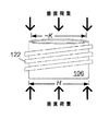
以下、図面に参照して詳述する。図1には、成形金属容器への製品充填とクロージャーの取り付け中に該容器への垂直荷重を遮断して容器の変形を緩和するためのシステムと方法の1例が示されていることが見て取れよう。1つの代表的態様においては、複数の成形金属容器102A〜102Cを、複数の円筒状金属管を用いて形成して、移送機304に載せて移送することができる。次に、保持リングを成形金属容器102A〜102Cに形成または取り付けることができる。保持リング支持体302A〜302Bを用いて、成形金属容器への製品充填とクロージャー202の取り付け中に該容器を支持することができる。この点については、成形金属容器102Cへの充填またはクロージャー202の取り付け中に、保持リングと成形金属容器102Cの開口端との間で垂直荷重を遮断することができる。
Hereinafter, it will be described in detail with reference to the drawings. It can be seen in FIG. 1 that one example of a system and method for mitigating container deformation by blocking vertical loading on a container during product filling and closure installation in a molded metal container is shown. Like. In one exemplary embodiment, a plurality of molded
本明細書では、「垂直荷重(column loading)」(「アキシアル荷重(axially loading)」とも称する)は、一次軸(primary axis)と同軸方向に沿うかまたは平行な方向の荷重または力と定義される。この場合、一次軸は、成形金属容器102の頭頂の開口端から底部の封止端へ延びる軸である。1つの代表的態様においては、そのような垂直荷重は、成形金属容器102へ製品を充填する場合、成形金属容器102にクロージャーを取り付ける場合、または、成形金属容器を垂直方向に積み重ねる場合(たとえば物流用パレットの上に積み重ねる時、商店での陳列時、最終完成製品を貯蔵する時など)に典型的に生じ、また、特定の態様において要求され及び/又は所望されるのに応じて他の状況においても生ずる。
As used herein, “column loading” (also referred to as “axially loading”) is defined as a load or force in a direction along or parallel to the primary axis. The In this case, the primary axis is an axis extending from the open end at the top of the shaped
本明細書ではさらに、円筒状管とは、円筒状の表面で包まれる空間として定義される。1例としては、飲料用容器などの容器は円筒状管と呼ぶことができる。さらに、成形容器102は成形金属容器と呼ぶことができる。
Further herein, a cylindrical tube is defined as a space enclosed by a cylindrical surface. As an example, a container such as a beverage container can be referred to as a cylindrical tube. Further, the shaped
保持リングと成形金属容器102A〜102Cの開口端との間の領域で垂直荷重を遮断することの利点は、成形金属容器の保持リングより下の領域に垂直荷重がかからないことである。こうして、保持リングと成形金属容器の開口端との間の領域で垂直荷重を遮断することにより、金属その他の材料から製造した、壁厚のより小さい成形容器を使用できるようになり、つまり、従来技術においては大きな垂直荷重で変形したり潰れたりする可能性のある小さい壁厚を有する成形容器を問題なく使用できる。経済的利益としては、壁厚のより小さい成形容器は、製造用材料を減量することができるので、製造コストを削減することができる。この利益は、金属容器の場合に特に当てはまるものである。マーケティングおよび容器製造における利益としては、壁厚のより小さい容器は、成形がより容易であり、種々の成形方法で高度に成形することができる。成形方法としては、たとえばブロー成形、圧力ラム、エンボス加工、ロール加工、液圧成形、空気圧成形またはスタンピングにより成形された一対の半部材の使用など、特定の態様において要求され及び/又は所望されるのに応じて種々の成形方法が使用できる。
The advantage of blocking the vertical load in the region between the retaining ring and the open ends of the formed
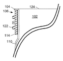
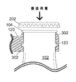
図2A〜2Cに、垂直荷重を受けるアウトサート部品106(保持リング108を含む)を含む、製品容器102(「成形容器102」または「成形金属容器102」とも表記する)の1例を示す。図2Aは、容器の開口端の周囲に配置されたアウトサート部品106を含む成形容器102を示す。図2Bは、ロール済み周縁部104の下方に位置するアウトサート部品106を含む成形容器102の断面を示す。本明細書においては、成形した、滑らかな、または他の形の周縁部を、「ロール済み周縁部」と称する。
2A-2C illustrate an example of a product container 102 (also referred to as a “formed
図2Cは、ロール済み周縁部104の下方に位置するアウトサート部品106を含む成形容器102の断面図を示す。ロール済み周縁部104はアウトサート部品106と連結して、ねじ込み式のクロージャーの取り付けまたは取り外しの際にアウトサート部品106が容器の頸部の周囲で滑るのを防止する。
FIG. 2C shows a cross-sectional view of the molded
1つの代表的態様においては、保持リング108を有する円形のアウトサート部品106、および、所望により、取り外し可能のクロージャー202(図には示さない)を係合して保持するためのねじ山122を、成形容器102の開口端の外周に取り付けることができる。該所望により用いるねじ山は、複数のものであってよく、アウトサート部品の外側表面に螺旋状に設けられ、成形金属容器とは別個の容器クロージャーを容器のボディに係合して保持する。図2Bはまた、成形容器102の薄厚側壁の断面110がどのようにして容器の開口端124の頂部に位置するロール済み周縁部104またはその他の成形周縁部104となり得るかを示す。ロール済み周縁部104は、アウトサート部品106が成形容器102の開口端124から滑り落ちないように保持し、同時に、人間の口と接触する滑らかな周縁部を提供して消費者が成形容器102から製品を注いで飲む際に快適感を与える。
In one exemplary embodiment, a
1つの代表的態様においては、アウトサート部品106の長さ‘B’は、5 mm 〜30 mm の範囲であり、好ましくは20 mm より小さい。開口部の長さ‘H’は、13 mm 〜50 mm の範囲である。ロール済み周縁部の長さ‘I’は、0.25 mm 〜5 mm の範囲であり、好ましくは3 mm より小さい。開口部の直径‘K’は、10 mm 〜47 mm の範囲であり、好ましくは32 mm より小さい。
In one exemplary embodiment, the length 'B' of the
図2Bに示す代表的態様においては、アウトサート部品106は、特定の態様において要求され及び/又は所望されるのに応じて、ポリマー、金属若しくはガラス又はその他の材料から製造することができる。さらに、アウトサート部品106は、特定の態様において要求され及び/又は所望されるのに応じて、王冠型、ねじ込み式蓋栓型、ロールオン ピルファー プルーフ(ROPP)蓋栓型などのクロージャー、プラスチック製のクロージャー、またはスナップ式蓋栓型若しくはその他の型式のクロージャーと組み合わせて用いることができる。王冠は、特定の態様において要求され及び/又は所望されるのに応じて、金属、プラスチックまたはその他の材料のものでよい。プラスチック製のクロージャーは、特定の態様において要求され及び/又は所望されるのに応じて、ねじ込み式、ねじ切り(twist-off)式またはその他の型式のものを用いることができる。1つの代表的態様においては、保持リングの長さ‘Q’は、1 mm 〜10 mm の範囲であり、好ましくは5 mm より小さい。
In the exemplary embodiment shown in FIG. 2B, the
図2Cに示す代表的態様においては、アウトサート部品106は、特定の態様において要求され及び/又は所望されるのに応じて、ポリマー、金属若しくはガラス又はその他の材料から製造することができる。さらに、アウトサート部品は、特定の態様において要求され及び/又は所望されるのに応じて、王冠型、ねじ込み式蓋栓型、ロールオン ピルファー プルーフ(ROPP)蓋栓型などのクロージャー、プラスチック製のクロージャー、またはスナップ式蓋栓型若しくはその他の型のクロージャーと組み合わせて用いることができる。王冠は、特定の態様において要求され及び/又は所望されるのに応じて、金属、プラスチックまたはその他の材料のものでよい。プラスチック製のクロージャーは、特定の態様において要求され及び/又は所望されるのに応じて、ねじ込み式、ねじ切り式またはその他の型式のものを用いることができる。アウトサート部品の頭頂にある段は、アウトサート部品の上端周縁部を覆うように容器材料がせり出すことを許容するものであり、このせり出し部分がアウトサート部品を把持し、クロージャーを容器に取り付けたり容器から取り外したりする際にアウトサート部品が回転したり滑ったりしないように保持するために役立つものである。
In the exemplary embodiment shown in FIG. 2C, the
1つの代表的態様においては、保持リングの長さ‘Q’は、1 mm 〜10 mm の範囲であり、好ましくは5 mm より小さい。さらに、成形容器のロール済み周縁部104は、アウトサート部品106の頭端部でアウトサート部品106を係合して、クロージャーを成形容器102に取り付け及び/又は成形容器102から取り外す際にアウトサート部品106がボディテーパー部の外周上で回転するのを防止することができる。別の代表的態様においては、ロール済み周縁部104は、アウトサート部品106を係合してアウトサート部品と一体化するような形状となっており、これにより人間の口と接触する滑らかな周縁部を提供することができる。アウトサート部品106を係合して固定するこのようなロール済み周縁部を用いる方法は、特定の態様において要求され及び/又は所望されるのに応じて、本発明の他の態様に適用することができる。
In one exemplary embodiment, the retaining ring length 'Q' is in the range of 1 mm to 10 mm, preferably less than 5 mm. In addition, the rolled
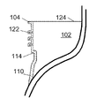
図3A〜3Bに、垂直荷重を受けるアウトサート部品106を含む製品容器102(「成形容器102」とも表記する)の1例を示す。アウトサート部品106はさらに、取り外し可能のクロージャー202(図には示さない)に係合して保持するためのねじ山122を所望により有している。1つの代表的態様においては、該所望により用いるねじ山は、複数のものであってよく、アウトサート部品の外側表面に螺旋状に設けられ、成形金属容器とは別個の容器クロージャーを容器のボディに係合して保持する。容器102は、ロール済み周縁部104をさらに含む。図3Aは、容器の開口端の周囲に配置されたアウトサート部品106を含む成形容器102を示す。図3Bは、ロール済み周縁部104の下方に位置するアウトサート部品106を含む成形容器102の断面を示す。
3A-3B show an example of a product container 102 (also referred to as “molded
図2A〜2Bに示すアウトサート部品の場合とは対照的に、図3A〜3Bに示す代表的態様におけるアウトサート部品の場合は、成形容器102の一端の頸部を成形して保持リングとして機能する端部を形成することによって保持リングを設け、アウトサート部品106を成形容器102の開口端124に取り付けた時にアウトサート部品106の下側周縁部の下に空隙112が生ずる。これは、成形容器のボディテーパー部に、デボス加工された領域をボディテーパー部と一体的に設けることであると言える。本明細書においては、保持リングとして機能する端部114のような保持リングとして機能する端部をも、保持リングと称することができる。
In contrast to the case of the outsert part shown in FIGS. 2A to 2B, in the case of the outsert part in the exemplary embodiment shown in FIGS. 3A to 3B, the neck part at one end of the molded
図3Bはまた、成形容器102の薄厚側壁の断面110がどのようにして容器の開口端124の頭頂部に位置するロール済み周縁部104またはその他の成形周縁部104となり得るかを示す。ロール済み周縁部104は、アウトサート部品106が成形容器102の開口端124から滑り落ちないように保持し、同時に、滑らかな周縁部を提供して消費者が成形容器102から製品を注いで飲む際に快適感を与える。
FIG. 3B also illustrates how the
1つの代表的態様においては、アウトサート部品106は、特定の態様において要求され及び/又は所望されるのに応じて、ポリマー、金属若しくはガラス又はその他の材料から製造することができる。さらに、アウトサート部品は、特定の態様において要求され及び/又は所望されるのに応じて、王冠型、ねじ込み式蓋栓型、ロールオン ピルファー プルーフ(ROPP)蓋栓型などのクロージャー、プラスチック製のクロージャー、またはスナップ式蓋栓型若しくはその他の型式のクロージャーと組み合わせて用いることができる。王冠は、特定の態様において要求され及び/又は所望されるのに応じて、金属、プラスチックまたはその他の材料のものでよい。プラスチック製のクロージャーは、特定の態様において要求され及び/又は所望されるのに応じて、ねじ込み式、ねじ切り(twist-off)式またはその他の型式のものを用いることができる。アウトサート部品106の下端部が構成する、保持リングとして機能する端部114は、保持リングとして機能し、保持リングと称することもできる。
In one exemplary embodiment, the
1つの代表的態様においては、アウトサート部品106の長さ‘B’は、5 mm 〜30 mm の範囲であり、好ましくは20 mm より小さい。開口部の長さ‘H’は、13 mm 〜50 mm の範囲である。ロール済み周縁部の長さ‘I’は、0.25 mm 〜5 mm の範囲であり、好ましくは3 mm より小さい。開口部の直径‘K’は、10 mm 〜47 mm の範囲であり、好ましくは32 mm より小さい。保持リングとして機能する端部の長さ‘P’は、2.5 mm 〜10 mm の範囲であり、好ましくは7 mm より小さい。
In one exemplary embodiment, the length 'B' of the
図4A〜4Bに、容器と一体的なねじ山および容器と一体的な保持リングを含む製品容器102(「成形容器102」とも表記する)の1例を示す。図4Aに示す代表的態様においては、ねじ山122、ロール済み周縁部104、および保持リング114は、容器102と一体的に形成することができる。この態様の1つの利点は、さらなるアウトサート部品や、図6A〜6Bに示す保持リング114A〜114Bのような別個の保持リングを必要としないことである。このことは、製造ラインの速度を高め、容器製造工程を簡素化し、容器102の製造費用の低減に繋がる。特定の態様において要求され及び/又は所望されるのに応じて、王冠型、ねじ込み式蓋栓型、ロールオン ピルファー プルーフ(ROPP)蓋栓型などのクロージャー、プラスチック製のクロージャー、またはスナップ式蓋栓型若しくはその他の型式のクロージャーを用いることができる。要求され及び/又は所望されるのに応じて、王冠は、金属、プラスチックまたはその他の材料でできているものでよい。プラスチック製のクロージャーは、特定の態様において要求され及び/又は所望されるのに応じて、ねじ込み式、ねじ切り式またはその他の型式のものでよい。
4A-4B illustrate an example of a product container 102 (also referred to as “molded
1つの代表的態様においては、アウトサート部品106の長さ‘B’は、5 mm 〜30 mm の範囲であり、好ましくは20 mm より小さい。開口部の長さ‘H’は、13 mm 〜50 mm の範囲である。ロール済み周縁部の長さ‘I’は、0.25 mm 〜5 mm の範囲であり、好ましくは3 mm より小さい。開口部の直径‘K’は、10 mm 〜47 mm の範囲であり、好ましくは32 mm より小さい。保持リングとして機能する端部の長さ‘P’は、2.5 mm 〜10 mm の範囲であり、好ましくは7 mm より小さい。
In one exemplary embodiment, the length 'B' of the
図4Bはまた、成形容器102の薄厚側壁の断面110がどのようにして容器102の開口端124の頭頂部に位置するロール済み周縁部104またはその他の成形周縁部104となり得るかを示す。ねじ山122および保持リング114は、容器の側壁110と一体的であり、この態様においてはアウトサート部品は不要である。
4B also illustrates how the
図5A〜5Bに、内側へ延びる、容器と一体的な保持リングを含む、製品容器102(「成形容器102」とも表記する)の1例を示す。図5Bは、成形容器102の開口端124の断面を示し、側壁110、形成されている周縁部104、および形成されている保持リング120を示す。1つの代表的態様においては、保持リング120は、成形容器102の側壁の中に形成することができる。本発明の1つの利点は、保持リングを成形容器の側壁の中に形成することによって、別個の保持リングやアウトサート部品が不要になることである。
5A-5B show an example of a product container 102 (also referred to as “molded
図5Aに示す代表的態様においては、アウトサート部品106の長さ‘B’は、5 mm 〜30 mm の範囲であり、好ましくは20 mm より小さい。開口部の長さ‘H’は、13 mm 〜50 mm の範囲である。ロール済み周縁部の長さ‘I’は、0.25 mm 〜5 mm の範囲であり、好ましくは3 mm より小さい。開口部の直径‘K’は、10 mm 〜47 mm の範囲であり、好ましくは32 mm より小さい。保持リングの長さ‘J’は、1 mm 〜8 mm の範囲であり、好ましくは5 mm より小さい。
In the exemplary embodiment shown in FIG. 5A, the length 'B' of the
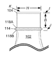
図6A〜6Dに、製品容器102(「成形容器102」とも表記する)の1例を示す。製品容器は、容器に挟み込まれ又は接着された、対称形状を有する保持リング114Bまたは非対称形状を有する保持リング114Aを含む。図6A〜6Bは、容器の開口端の周囲に配置されたアウトサート部品106を含む成形容器102を示す。図6Aは、成形された外周縁部(図6Bに示す保持リング114Bにおけるような連続的円周状の外周縁部とは異なる)を有する非対称保持リング114Aを示す。保持リングの内周は、成形容器102の開口端に嵌合する(fit around)ようなサイズになっている。1つの代表的態様においては、成形された外周縁部は、特定の態様において要求され及び/又は所望されるのに応じて、どのような形状をもとり得る。
6A to 6D show an example of a product container 102 (also referred to as “molded
図6Bは、対称保持リング114Bを示す。「対称」とは、保持リング114Bの外周縁部が連続的円周状の形状であることを意味する。保持リングの内周は、成形容器102の開口端に嵌合するようなサイズになっている。
FIG. 6B shows a
図6Cは、ロール済み周縁部104の近傍に位置する上側周縁部118Aと下側周縁部118Bとの間に挟み込まれ又は接着された保持リング114を含む成形容器102を示す。上側周縁部118Aと下側周縁部188Bとは、成形金属容器のボディテーパー部と一体となっている。
FIG. 6C shows the molded
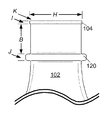
図6Dは、保持リング114を含む成形容器102を示す。保持リング114は、成形金属容器102のボディテーパー部に容器と一体的に形成されている下側の棚と、容器と一体的に形成されている上側周縁部118Bとの間に挟み込まれ又は接着されている。保持リング114は、下側の棚の上に載っている。容器と一体的に形成されている上側周縁部118Bは、保持リング114を下側の棚と上側周縁部との間に挟み込み又は接着している。上側周縁部118Aと下側の棚とは、成形金属容器のボディテーパー部と一体となっている。本明細書では、下側の棚を「下側周縁部」とも称する。
FIG. 6D shows the molded
図6C〜6Dに示す代表的態様においては、開口端の長さ‘B’は、5 mm 〜30 mm の範囲であり、好ましくは20 mm より小さい。開口部の長さ‘H’は、13 mm 〜50 mm の範囲である。ロール済み周縁部の長さ‘I’は、0.25 mm 〜5 mm の範囲であり、好ましくは3 mm より小さい。開口部の直径‘K’は、10 mm 〜47 mm の範囲であり、好ましくは32 mm より小さい。保持リングは下側周縁部と上側周縁部との間に挟み込まれ又は接着されており、下側周縁部、上側周縁部および保持リングの長さの合計‘J’は、1 mm 〜8 mm の範囲であり、好ましくは5 mm より小さい。 In the exemplary embodiment shown in FIGS. 6C-6D, the open end length 'B' ranges from 5 mm to 30 mm, preferably less than 20 mm. The length ‘H’ of the opening is in the range of 13 mm to 50 mm. The length ‘I’ of the rolled periphery is in the range of 0.25 mm to 5 mm, preferably less than 3 mm. The diameter of the opening 'K' is in the range of 10 mm to 47 mm, preferably less than 32 mm. The retaining ring is sandwiched or bonded between the lower peripheral edge and the upper peripheral edge, and the total length “J” of the lower peripheral edge, the upper peripheral edge and the retaining ring is 1 mm to 8 mm. Range, preferably less than 5 mm.
1つの代表的態様においては、下側周縁部118Bは、成形容器102の側壁の中にボディテーパー部と一体的に形成することができる。保持リング114は、成形容器102の開口端の外周に嵌合させることができる。上側周縁部118Aは、下側周縁部118Bおよび保持リング114の上方にボディテーパー部と一体的に形成することができる。保持リング114は、上側周縁部118Aと下側周縁部118Bとの間に挟み込みまたは接着させて保持される。
In one exemplary embodiment, the lower
図7A〜7Bに、外側へ延びる一体的な保持リングを含む製品容器102(「成形容器102」とも表記する)の1例を示す。図7Aは、外側へ延びる一体的な保持リング120を含む成形容器102を示す。図7Bは、成形容器102の開口端124の断面を示し、側壁110、形成されている周縁部104、および形成されている保持リング120を示す。1つの代表的態様においては、保持リング120は、成形容器102の側壁の中に容器と一体的に形成することができる。
7A-7B illustrate an example of a product container 102 (also referred to as “molded
この代表的態様における1つの利点は、保持リングを成形容器の側壁の中に形成することによって、別個の保持リングやアウトサート部品が不要になることである。 One advantage of this exemplary embodiment is that a separate retaining ring or outsert component is not required by forming the retaining ring in the side wall of the molded container.
1つの代表的態様においては、開口端の長さ‘B’は、5 mm 〜30 mm の範囲であり、好ましくは20 mm より小さい。開口部の長さ‘H’は、13 mm 〜50 mm の範囲である。ロール済み周縁部の長さ‘I’は、0.25 mm 〜5 mm の範囲であり、好ましくは3 mm より小さい。開口部の直径‘K’は、10 mm 〜47 mm の範囲であり、好ましくは32 mm より小さい。保持リングは下側周縁部と上側周縁部との間に挟み込まれ又は接着されており、下側周縁部、上側周縁部および保持リングの長さの合計‘J’は、1 mm 〜8 mm の範囲であり、好ましくは5 mm より小さい。 In one exemplary embodiment, the open end length 'B' ranges from 5 mm to 30 mm, preferably less than 20 mm. The length ‘H’ of the opening is in the range of 13 mm to 50 mm. The length ‘I’ of the rolled periphery is in the range of 0.25 mm to 5 mm, preferably less than 3 mm. The diameter of the opening 'K' is in the range of 10 mm to 47 mm, preferably less than 32 mm. The retaining ring is sandwiched or bonded between the lower peripheral edge and the upper peripheral edge, and the total length “J” of the lower peripheral edge, the upper peripheral edge and the retaining ring is 1 mm to 8 mm. Range, preferably less than 5 mm.
図8に、垂直荷重を受けるアウトサート部品106の1例を示す。1つの代表的態様においては、アウトサート部品106は、成形容器102の開口端124の周囲に配置され、所望によりねじ山122を有する。ねじ山122は、取り外し可能のクロージャー202(図には示さない)を係合して保持するためのものであり、容器の開口端にクロージャーを取り付ける際に保持リングまたは保持リングとして機能する周縁部が垂直荷重を支えるように設計されている。該所望により用いるねじ山は、複数のものであってよく、アウトサート部品の外側表面に螺旋状に設けられ、成形金属容器とは別個の容器クロージャーを容器のボディに係合して保持する。このようなアウトサート部品は、特定の態様において要求され及び/又は所望されるのに応じて、プラスチック、金属または他の材料から製造することができる。
FIG. 8 shows an example of the
1つの代表的態様においては、製品を充填するときまたはクロージャーを取り付けるときの垂直荷重は、たとえば、クロージャーが王冠型のものである場合には600ポンド(lbs)〜800 lbs の範囲、クロージャーがROPP蓋栓型のものである場合には300 lbs 〜500 lbs の範囲、クロージャーがプラスチック製のねじ込み式またはねじ切り式のものである場合には30 lbs 〜80 lbs の範囲であるが、これらに限定されるものではない。 In one exemplary embodiment, the vertical load when filling the product or installing the closure is, for example, in the range of 600 pounds (lbs) to 800 lbs when the closure is of the crown type, and the closure is ROPP The range is 300 lbs to 500 lbs if it is a cap type, or 30 lbs to 80 lbs if the closure is a plastic screw-in or threaded type. It is not something.
本明細書では、「垂直荷重」(「アキシアル荷重」とも称する)は、一次軸と同軸方向に沿うかまたは平行な方向の荷重または力と定義される。この場合、一次軸は、成形金属容器102の頭頂の開口端から底部の封止端へ延びる軸である。1つの代表的態様においては、そのような垂直荷重は、成形金属容器102へ製品を充填する場合、成形金属容器102にクロージャーを取り付ける場合、または、成形金属容器を垂直方向に積み重ねる場合(たとえば物流用パレットの上に積み重ねる時、商店での陳列時、最終完成製品を貯蔵する時など)に典型的に生じ、また、特定の態様において要求され及び/又は所望されるのに応じて他の状況においても生ずる。
As used herein, “vertical load” (also referred to as “axial load”) is defined as a load or force in a direction along or parallel to the primary axis. In this case, the primary axis is an axis extending from the open end at the top of the shaped
1つの代表的態様においては、開口部の外周の長さ‘H’は、13 mm 〜50 mm の範囲である。開口部の内直径‘K’は、およそ、10 mm 〜47 mm の範囲であり、好ましくは32 mm より小さく、アウトサート部品106はボディテーパー部の開口端近傍の外周に嵌合する。
In one exemplary embodiment, the outer peripheral length ‘H’ of the opening is in the range of 13 mm to 50 mm. The inner diameter 'K' of the opening is approximately in the range of 10 mm to 47 mm, preferably less than 32 mm, and the
図9に、アウトサート部品106を含む製品容器102(「成形容器102」とも表記する)、およびねじ込み式スクリューキャップ型クロージャー202の取り付けの1例を示す。製品容器102は、保持リング支持体302の使用を介して垂直荷重を受ける。1つの代表的態様においては、保持リング支持体302は、成形容器102をクロージャー取り付け工程を行なう場所まで移送するためのシステムと連結している。クロージャー取り付けシステムはクロージャー202を取り付けることができるが、その際、クロージャーが王冠型のものである場合には600ポンド(lbs)〜800 lbs の範囲の垂直荷重、クロージャーがROPP蓋栓型のものである場合には300 lbs 〜500 lbs の範囲の垂直荷重、クロージャーがプラスチック製のねじ込み式またはねじ切り式のものである場合には30 lbs 〜80 lbs の範囲の垂直荷重を、それぞれ通常引き起こす。このように、垂直荷重は、用いるクロージャーの型式や種類に応じて異なる。
FIG. 9 shows an example of attachment of a product container 102 (also referred to as “molded
クロージャーの取り付けの間、保持リング支持体302は、保持リング108を介して成形容器102を支持する。この点について、垂直荷重は、保持リング118と成形容器102(アウトサート部品106を含み、所望によりさらに、クロージャー202を受けて係合するためのねじ山を含む)の開口端との間の領域で遮断される。1つの代表的態様においては、該所望により用いるねじ山は、複数のものであってよく、アウトサート部品の外側表面に螺旋状に設けられ、成形金属容器とは別個の容器クロージャーを容器のボディに係合して保持する。
During attachment of the closure, the retaining
図10A〜10Bに、王冠型クロージャー202を含む製品容器102(「成形容器102」とも表記する)の1例を示す。図10Aは、保持リング支持体302によって支持されるロール済み周縁部104を含む成形容器102を示す。図10Bは、保持リング120を含む成形容器102に嵌合する形状を有する保持リング支持体302の断面を示す。
FIGS. 10A to 10B show an example of a product container 102 (also referred to as “molded
1つの代表的態様においては、王冠型クロージャー202は、特定の態様において要求され及び/又は所望されるのに応じて、スズ、鋼、アルミニウム及び/又はその他の金属でできているものでよい。また、別の代表的態様においては、王冠型クロージャー202は、特定の態様において要求され及び/又は所望されるのに応じて、プラスチック、ポリマー、ポリプロピレン(PP)、高密度ポリエチレン(HDPE)またはその他の材料でできているものでよい。非金属製の王冠型クロージャー202は、特定の態様において要求され及び/又は所望されるのに応じて、所望により、塗布、メッキ、またはその他のコーティング方法により金属で被覆する最終加工を行うことにより、プラスチック製のものが金属製に見える外観になっていてもよい。
In one exemplary embodiment, the
1つの代表的態様においては、保持リング支持体302は、成形容器102と相補的な形状を有するものでよい。この場合、垂直荷重は、より広い表面に分配され、保持リング120によっても支えられるため、垂直荷重による影響を減じ、その結果、製品を充填する時及び/又はクロージャー202を取り付ける時の成形容器102の保持リング120より下の部分の変形や潰れを減ずることができる。
In one exemplary embodiment, the retaining
1つの利点は、より薄い壁厚の容器を用いることができ、これにより、成形容器102の材料費が節約でき、製品容器の製造費用の低減と、形成及び/又はその他の成形がより容易であるより薄い側壁を有する容器の製造とに繋がることである。この態様においては、クロージャー202を取り付ける時の垂直荷重が、保持リング支持体302、およびネックリング120と成形容器102の開口端との間の容器材料で支えられる。
One advantage is that thinner wall thickness containers can be used, thereby saving the material costs of the molded
図11に、成形容器102の1例を示す。成形容器102は、特定の好ましい態様における寸法比をもって特徴付けることができる。このような成形容器102は、特定の態様において要求され及び/又は所望されるのに応じて、直線的な側壁を有していてもよい。アウトサート部品106の長さ‘B’は、5 mm 〜30 mm の範囲であり、好ましくは20 mm より小さい。開口部の長さ‘H’は、13 mm 〜50 mm の範囲である。ロール済み周縁部の長さ‘I’は、0.25 mm 〜5 mm の範囲であり、好ましくは3 mm より小さい。開口部の直径‘K’は、10 mm 〜47 mm の範囲であり、好ましくは27 mm より小さい。
FIG. 11 shows an example of the molded
複数の代表的な態様においては、成形容器のサイズは、特定の態様において要求され及び/又は所望されるのに応じて、小さかったり、中くらいであったり、大きかったりする。典型的な500ミリリットル(ml)容器の場合の寸法比の代表例を以下に挙げるが、これに限定されるものではない。成形容器120の全長‘A’は、230 mm 〜280 mm の範囲であり、好ましくは251 mm である。容器のボディテーパー部の最小直径‘L’は、20 mm 〜30 mm の範囲であり、好ましくは25 mm である。ボディ中央部の最大直径‘M’は、50 mm 〜80 mm の範囲であり、好ましくは68mmである。ボディ下部の最小直径‘N’は、45 mm 〜70 mm の範囲であり、好ましくは59 mm である。底部の最大直径‘O’は、50 mm 〜75 mm の範囲であり、好ましくは69 mm である。ボディテーパー部の長さ‘C’は、80 mm 〜100の範囲であり、好ましくは80 mm である。ボディ中央部の長さ‘D’は、20 mm 〜50 mm の範囲であり、好ましくは30 mm である。ボディ下部の長さ‘E’は、100 mm 〜120 mm の範囲であり、好ましくは106 mm である。底部の長さ‘F’は、18 mm 〜30 mm の範囲であり、好ましくは22 mm である。成形容器102の長さ‘G’は、50 mm 〜75 mm の範囲であり、好ましくは69 mm より小さい。
In some exemplary embodiments, the size of the molded container may be small, medium, or large, as required and / or desired in a particular embodiment. Representative examples of the dimensional ratio in the case of a typical 500 milliliter (ml) container are listed below, but are not limited thereto. The total length 'A' of the molded
成形容器102が金属から製造される代表的な態様においては、金属の厚さは0.0030インチ〜0.0250インチの範囲である。
In an exemplary embodiment where the shaped
1つの代表的態様においては、成形容器は金属製のものでよい。薄厚側壁を有する金属製の成形容器ボディはボディテーパー部を有し、ボディテーパー部はボディテーパー部と一体的なロール済み周縁部(ロール済み周縁部の長さは‘I’である)を有する開口端(開口部の直径は‘K’である)を含む。成形容器ボディはさらに、直径‘M’のボディ中央部、直径‘N’のボディ下部、および直径‘O’の底部を含み、底部はボディ下部の一端を封止している。ボディ下部はボディ中央部と一体化しており、ボディ中央部はボディテーパー部と一体化している。 In one exemplary embodiment, the molded container may be metallic. A metal molded container body having a thin side wall has a body taper portion, and the body taper portion has a rolled peripheral edge (the length of the rolled peripheral edge is 'I') integral with the body taper. Includes open end (opening diameter is 'K'). The molded container body further includes a body central portion having a diameter 'M', a lower body portion having a diameter 'N', and a bottom portion having a diameter 'O', and the bottom portion seals one end of the lower portion of the body. The lower part of the body is integrated with the central part of the body, and the central part of the body is integrated with the tapered body part.
別の代表的態様においては、開口部の直径‘K’、ボディ中央部の直径‘M’、ボディ下部の直径‘N’、および底部の直径‘O’の間に、たとえば、‘K’<‘M’、‘M’>‘N’ および ‘N’<‘O’ という関係が成り立つが、これに限られるものではない。 In another exemplary embodiment, between the opening diameter “K”, the body center diameter “M”, the body lower diameter “N”, and the bottom diameter “O”, for example, “K” < The relations 'M', 'M'> 'N' and 'N' <'O' hold true, but are not limited to this.
この代表的態様においては、内径がほぼ‘K’、外径が‘H’、長さが‘B’であるアウトサート部品は、ボディテーパー部の開口端近傍の外周に嵌合している。アウトサート部品は、アウトサート部品の外周に形成されている保持リング、および複数のねじ山を含む。複数のねじ山は、アウトサート部品の外側表面に螺旋状に設けられており、成形容器とは別個の容器クロージャーを成形容器ボディに係合して保持するためのものである。 In this representative embodiment, an outsert part having an inner diameter of approximately 'K', an outer diameter of 'H', and a length of 'B' is fitted to the outer periphery in the vicinity of the opening end of the body taper portion. The outsert component includes a retaining ring formed on the outer periphery of the outsert component and a plurality of threads. The plurality of threads are spirally provided on the outer surface of the outsert component, and are for engaging and holding a container closure separate from the molded container to the molded container body.
別の代表的態様においては、長さ‘E’を有する複数の第1溝130A〜130D(概ね長方形である)は、成形容器102のボディ下部に沿って方向付けされていてよい。特定の態様において要求され及び/又は所望されるのに応じて、複数の第1溝は、ボディ中央部の近傍に位置する隆起したエンボス加工された上側縁部、および、底部と一体化している下側縁部をさらに含む。このような溝は、特定の態様において要求され及び/又は所望されるのに応じて、本明細書に記載した任意の成形方法またはその他の成形方法によって形成することができる。
In another exemplary embodiment, a plurality of first grooves 130 </ b> A- 130 </ b> D (generally rectangular) having a length of “E” may be oriented along the lower body portion of the molded
別の代表的態様においては、長さ‘C’を有する複数の第2溝126A〜126D(概ね長方形である)は、成形容器のボディテーパー部に沿って方向付けされていてよい。特定の態様において要求され及び/又は所望されるのに応じて、複数の第2溝は、ボディ中央部の近傍に位置する隆起したエンボス加工された下側縁部、および、開口端と一体化している上側縁部をさらに含む。このような溝は、特定の態様において要求され及び/又は所望されるのに応じて、本明細書に記載した任意の成形方法またはその他の成形方法によって形成することができる。
In another exemplary embodiment, a plurality of
別の代表的態様においては、ラベル領域132を、ボディ中央部の近傍に形成してもよいし、また、複数の第1溝130A〜130Dの上側縁部とボディ中央部の近傍に位置する複数の第2溝126A〜126Dの下側縁部とによって規定される境界に形成してもよい。特定の態様において要求され及び/又は所望されるのに応じて、ラベル領域132は、エンボス加工またはデボス加工により形成された複数の表示記号128を含んでいてもよい。
In another representative aspect, the
1つの代表的態様においては、成形容器は、ボディテーパー部、ボディ中央部(直径‘M’を有する)、ボディ下部(直径‘N’を有する)および底部(直径‘O’を有する)を含む。ボディテーパー部は、ロール済み周縁部(長さ‘I’を有する)を有する開口端(開口部の直径は‘K’である)を含み(これにより、人間の口と接触する滑らかな表面を形成する)、さらに、ボディテーパー部の特定部分(長さが‘J’であって、開口端からの距離‘B’の位置にある部分)の外周にボディテーパー部と一体的に取り付けられたネックリングを含む。ネックリングはボディテーパー部から外側または内側に延びている。底部はボディ下部の一端を封止しており、ボディ下部はボディ中央部と一体化しており、ボディ中央部はボディテーパー部と一体化しており、それによって薄厚側壁を有する金属製の成形容器ボディを形成している。 In one exemplary embodiment, the molded container includes a body taper, a body center (having a diameter 'M'), a lower body (having a diameter 'N'), and a bottom (having a diameter 'O'). . The body taper includes an open end (the diameter of the opening is 'K') with a rolled peripheral edge (having a length 'I'), which provides a smooth surface that contacts the human mouth. In addition, the body taper portion is integrally attached to the outer periphery of the specific portion of the body taper portion (the length is “J” and is located at a distance “B” from the opening end). Includes neck ring. The neck ring extends outward or inward from the body taper portion. The bottom part seals one end of the lower part of the body, the lower part of the body is integrated with the center part of the body, and the central part of the body is integrated with the body taper part, thereby forming a metal molded container body having a thin side wall. Is forming.
この態様においては、特定の態様において要求され及び/又は所望されるのに応じて、複数の第1溝、複数の第2溝、ラベル領域、エンボス加工及び/又はデボス加工により形成された表示記号128、及び/又は他の特徴を有してよい。特定の態様において要求され及び/又は所望されるのに応じて、‘K’、‘M’、‘N’および‘O’の間に、‘K’<‘M’、‘M’>‘N’ および ‘N’<‘O’ という関係が成り立ってよい。
In this aspect, a plurality of first grooves, a plurality of second grooves, label regions, embossing and / or debossing symbols as required and / or desired in a
別の代表的態様においては、成形容器は、保持リングおよびボディテーパー部を含む。ボディテーパー部は、ロール済み周縁部(長さ‘I’を有する)を有する開口端(開口部の直径は‘K’である)を含み、これにより、人間の口と接触する滑らかな表面を形成する。下側周縁部が、ボディテーパー部と一体的であり且つボディテーパー部の外周から外側に延びており、上側周縁部が、ボディテーパー部と一体的であり且つボディテーパー部の外周から外側に延びており、保持リングは、下側周縁部の上に配置され、下側周縁部と開口端近傍に位置する上側周縁部との間に挟み込まれ又は接着されている。ボディ中央部の直径は‘M’であり、ボディ下部の直径は‘N’であり、底部の直径は‘O’である。底部はボディ下部の一端を封止しており、ボディ下部はボディ中央部と一体化しており、ボディ中央部はボディテーパー部と一体化しており、それによって薄厚側壁を有する金属製の成形容器ボディを形成している。 In another exemplary embodiment, the molded container includes a retaining ring and a body taper. The body taper includes an open end (the diameter of the opening is 'K') having a rolled periphery (having a length 'I'), thereby providing a smooth surface in contact with the human mouth. Form. The lower peripheral edge is integral with the body taper and extends outward from the outer periphery of the body taper, and the upper peripheral edge is integral with the body taper and extends outward from the outer periphery of the body taper. The retaining ring is disposed on the lower peripheral edge and is sandwiched or bonded between the lower peripheral edge and the upper peripheral edge located in the vicinity of the opening end. The diameter at the center of the body is 'M', the diameter at the bottom of the body is 'N', and the diameter at the bottom is 'O'. The bottom part seals one end of the lower part of the body, the lower part of the body is integrated with the center part of the body, and the central part of the body is integrated with the body taper part, thereby forming a metal molded container body having a thin side wall. Is forming.
この態様においては、特定の態様において要求され及び/又は所望されるのに応じて、複数の第1溝130A〜130D、複数の第2溝126A〜126D、ラベル領域132、エンボス加工及び/又はデボス加工により形成された表示記号128、及び/又は他の特徴を有してよい。特定の態様において要求され及び/又は所望されるのに応じて、‘K’、‘M’、‘N’および‘O’の間に、‘K’<‘M’、‘M’>‘N’ および ‘N’<‘O’ という関係が成り立ってよい。
In this aspect, a plurality of
別の代表的態様においては、成形容器は、金属製の成形容器ボディを含む。成形容器ボディは、ボディテーパー部を含む。ボディテーパー部は、ボディテーパー部と一体的なロール済み周縁部(長さ‘I’を有する)を有する開口端(開口部の直径は‘K’である)を含み、これにより、人間の口と接触する滑らかな表面を形成する。ボディテーパー部は、開口端近傍に、デボス加工された領域(その長さは‘B’+‘P’である)を含む。ボディ中央部の直径は‘M’であり、ボディ下部の直径は‘N’であり、底部の直径は‘O’である。底部は容器ボディの一端を封止しており、底部はボディ下部と一体化しており、ボディ下部はボディ中央部と一体化しており、ボディ中央部はボディテーパー部と一体化しており、‘K’<‘M’、‘M’>‘N’ および ‘N’<‘O’ という関係が成り立つ。 In another exemplary embodiment, the molded container includes a metal molded container body. The molded container body includes a body taper portion. The body taper includes an open end (the diameter of the opening is 'K') having a rolled peripheral edge (having a length 'I') integral with the body taper, thereby allowing a human mouth Form a smooth surface in contact with. The body taper portion includes a debossed region (its length is 'B' + 'P') in the vicinity of the opening end. The diameter at the center of the body is 'M', the diameter at the bottom of the body is 'N', and the diameter at the bottom is 'O'. The bottom part seals one end of the container body, the bottom part is integrated with the lower part of the body, the lower part of the body is integrated with the central part of the body, and the central part of the body is integrated with the body taper part. The relations “<“ M ”,“ M ”>“ N ”and“ N ”<“ O ”hold.
内径がほぼ‘K’、外径が‘H’、長さが‘B’であるアウトサート部品は、ボディテーパー部の開口端近傍の外周に嵌合している。アウトサート部品は、保持リングとして機能する端部と複数のねじ山とを含む。保持リング端部は、長さが‘P’であり、アウトサート部品の外周の、アウトサート部品の底部とデボス加工された領域の下側縁部との間にある部分に形成されている。複数のねじ山は、アウトサート部品の外側表面に螺旋状に設けられており、成形容器とは別個の容器クロージャーを成形容器ボディに係合して保持するためのものである。 An outsert part having an inner diameter of approximately “K”, an outer diameter of “H”, and a length of “B” is fitted to the outer periphery of the body taper portion in the vicinity of the opening end. The outsert component includes an end that functions as a retaining ring and a plurality of threads. The retaining ring end is 'P' in length and is formed on the outer periphery of the outsert part, between the bottom of the outsert part and the lower edge of the debossed area. The plurality of threads are spirally provided on the outer surface of the outsert component, and are for engaging and holding a container closure separate from the molded container to the molded container body.
この態様においては、特定の態様において要求され及び/又は所望されるのに応じて、複数の第1溝130A〜130D、複数の第2溝126A〜126D、ラベル領域132、エンボス加工及び/又はデボス加工により形成された表示記号128、及び/又は他の特徴を有してよい。
In this aspect, a plurality of
本発明の好ましい態様について説明したが、現在および未来において、以下に示す本願の請求の範囲内に含まれる種々の改善や拡張を実施し得ることが当業者に理解される。これら請求項は、初めて記載した発明に対して適切な保護を維持するためのものと理解されたい。 While preferred embodiments of the present invention have been described, it will be appreciated by those skilled in the art that various improvements and enhancements may be made now and in the future which fall within the scope of the claims of this application. It is to be understood that these claims are intended to maintain adequate protection for the invention first described.
Claims (20)
薄厚側壁を有する金属製の成形容器ボディと、成形容器ボディに取り付けられた、複数のねじ山を有するアウトサート部品とを含み、
該成形容器ボディは、ボディテーパー部、ボディ中央部、ボディ下部および底部を含み、
ボディテーパー部はボディテーパー部と一体的なロール済み周縁部を有する開口端を含み、底部はボディ下部の一端を封止しており、ボディ下部はボディ中央部と一体化しており、ボディ中央部はボディテーパー部と一体化しており、
該アウトサート部品はボディテーパー部の開口端近傍の外周に嵌合しており、該アウトサート部品は該アウトサート部品の外周に形成されている保持リングを含み、
該複数のねじ山は、該アウトサート部品の外側表面に螺旋状に設けられており、成形金属容器とは別個の容器クロージャーを成形容器ボディに係合して保持するためのものである、
ことを特徴とする成形金属容器。 A molded metal container,
A metal molded container body having a thin sidewall, and an outsert part having a plurality of threads attached to the molded container body,
The molded container body includes a body taper part, a body center part, a body lower part and a bottom part,
The body taper portion includes an open end having a rolled peripheral edge that is integral with the body taper portion, the bottom portion seals one end of the lower body portion, and the lower body portion is integrated with the central body portion. Is integrated with the body taper,
The outsert part is fitted to the outer periphery in the vicinity of the opening end of the body taper part, and the outsert part includes a holding ring formed on the outer periphery of the outsert part,
The plurality of threads are spirally provided on the outer surface of the outsert part and are for engaging and holding a container closure separate from the molded metal container to the molded container body.
A molded metal container characterized by that.
ボディテーパー部、ボディ中央部、ボディ下部および底部を含み、
ボディテーパー部は、ボディテーパー部と一体的なロール済み周縁部を有する開口端、および、ボディテーパー部の開口端近傍の外周にボディテーパー部と一体的なネックリングを含み、
底部はボディ下部の一端を封止しており、ボディ下部はボディ中央部と一体化しており、ボディ中央部はボディテーパー部と一体化しており、それによって薄厚側壁を有する金属製の成形容器ボディを形成している、
ことを特徴とする成形金属容器。 A molded metal container,
Includes body taper, body center, lower body and bottom,
The body taper portion includes an opening end having a rolled peripheral edge portion integral with the body taper portion, and a neck ring integral with the body taper portion on the outer periphery in the vicinity of the opening end of the body taper portion,
The bottom part seals one end of the lower part of the body, the lower part of the body is integrated with the center part of the body, and the central part of the body is integrated with the body taper part, thereby forming a metal molded container body having a thin side wall. Forming the
A molded metal container characterized by that.
‘K’<‘M’、‘M’>‘N’ および ‘N’<‘O’ The following relationship is established among the diameter “K” of the opening, the diameter “M” of the center of the body, the diameter “N” of the lower part of the body, and the diameter “O” of the bottom. The molded metal container as described.
'K'<'M','M'>'N' and 'N'<'O'
保持リング、ボディテーパー部、ボディ中央部、ボディ下部および底部を含み、
ボディテーパー部は、ボディテーパー部と一体的なロール済み周縁部を有する開口端、ボディテーパー部と一体的であり且つボディテーパー部の外周から外側に延びる下側周縁部、および、ボディテーパー部と一体的であり且つボディテーパー部の外周から外側に延びる上側周縁部を有し、
保持リングは、下側周縁部の上に配置され、下側周縁部と開口端近傍に位置する上側周縁部との間に挟み込まれ又は接着されており、
底部はボディ下部の一端を封止しており、ボディ下部はボディ中央部と一体化しており、ボディ中央部はボディテーパー部と一体化しており、それによって薄厚側壁を有する金属製の成形容器ボディを形成している、
ことを特徴とする成形金属容器。 A molded metal container,
Includes retaining ring, body taper, body center, lower body and bottom
The body taper portion has an open end having a rolled peripheral edge portion integral with the body taper portion, a lower peripheral edge portion that is integral with the body taper portion and extends outward from the outer periphery of the body taper portion, and a body taper portion An upper peripheral portion that is integral and extends outward from the outer periphery of the body taper portion;
The retaining ring is disposed on the lower peripheral edge, and is sandwiched or adhered between the lower peripheral edge and the upper peripheral edge located in the vicinity of the opening end,
The bottom part seals one end of the lower part of the body, the lower part of the body is integrated with the center part of the body, and the central part of the body is integrated with the body taper part, thereby forming a metal molded container body having a thin side wall. Forming the
A molded metal container characterized by that.
Applications Claiming Priority (3)
| Application Number | Priority Date | Filing Date | Title |
|---|---|---|---|
| US12/618,362 | 2009-11-13 | ||
| US12/618,362 US8360266B2 (en) | 2009-11-13 | 2009-11-13 | Shaped metal vessel |
| PCT/US2010/055095 WO2011059854A1 (en) | 2009-11-13 | 2010-11-02 | Shaped metal vessel |
Related Child Applications (1)
| Application Number | Title | Priority Date | Filing Date |
|---|---|---|---|
| JP2016183732A Division JP6270946B2 (en) | 2009-11-13 | 2016-09-21 | Molded metal container |
Publications (2)
| Publication Number | Publication Date |
|---|---|
| JP2013510778A true JP2013510778A (en) | 2013-03-28 |
| JP2013510778A5 JP2013510778A5 (en) | 2013-12-19 |
Family
ID=43991960
Family Applications (2)
| Application Number | Title | Priority Date | Filing Date |
|---|---|---|---|
| JP2012538856A Pending JP2013510778A (en) | 2009-11-13 | 2010-11-02 | Molded metal container |
| JP2016183732A Active JP6270946B2 (en) | 2009-11-13 | 2016-09-21 | Molded metal container |
Family Applications After (1)
| Application Number | Title | Priority Date | Filing Date |
|---|---|---|---|
| JP2016183732A Active JP6270946B2 (en) | 2009-11-13 | 2016-09-21 | Molded metal container |
Country Status (12)
| Country | Link |
|---|---|
| US (1) | US8360266B2 (en) |
| EP (2) | EP2499066A4 (en) |
| JP (2) | JP2013510778A (en) |
| KR (2) | KR20120092664A (en) |
| CN (1) | CN102686495B (en) |
| AU (1) | AU2010319768B2 (en) |
| BR (1) | BR112012011394B1 (en) |
| CA (1) | CA2780887C (en) |
| IL (1) | IL219763A0 (en) |
| MX (1) | MX2012005639A (en) |
| WO (1) | WO2011059854A1 (en) |
| ZA (1) | ZA201203950B (en) |
Cited By (3)
| Publication number | Priority date | Publication date | Assignee | Title |
|---|---|---|---|---|
| JP2015105124A (en) * | 2013-11-29 | 2015-06-08 | 株式会社吉野工業所 | Synthetic resin blow container |
| JP2018162071A (en) * | 2017-03-24 | 2018-10-18 | ユニバーサル製缶株式会社 | Bottle can |
| JP2018162107A (en) * | 2018-06-21 | 2018-10-18 | ユニバーサル製缶株式会社 | Bottle can |
Families Citing this family (18)
| Publication number | Priority date | Publication date | Assignee | Title |
|---|---|---|---|---|
| CH703187A1 (en) * | 2010-05-27 | 2011-11-30 | Bottletec Gmbh | Container closure thread. |
| US8763829B2 (en) * | 2011-07-22 | 2014-07-01 | Craig Allen Madaus | Collapsible container for holding liquids or objects |
| BR122018017039B1 (en) | 2011-09-16 | 2020-01-21 | Ball Corp | process for manufacturing a container shaped from a tablet in an impact extrusion manufacturing process |
| MX2014009940A (en) * | 2012-02-17 | 2015-02-10 | Coca Cola Co | Metal beverage container with improved finish geometry. |
| US11952164B1 (en) | 2012-08-10 | 2024-04-09 | Powercan Holding, Llc | Resealable container lid and accessories including methods of manufacture and use |
| MX368657B (en) | 2013-03-15 | 2019-10-10 | Ball Corp | Method and apparatus for forming a threaded neck on a metallic bottle. |
| CN105324316B (en) | 2013-04-09 | 2018-01-12 | 鲍尔公司 | The Aluminum Bottle of the impact extrusion with threaded neck manufactured by the aluminium and the alloy of enhancing that recycle |
| JP6679492B2 (en) | 2014-02-07 | 2020-04-15 | ボール コーポレイションBall Corporation | Metal container with screwed closure |
| USD791593S1 (en) * | 2015-07-17 | 2017-07-11 | Cj Cheiljedang Corp. | Container for food packing |
| US10220983B1 (en) * | 2015-07-27 | 2019-03-05 | James R. Gilliam | Threaded bottle ring and method of fabrication and attachment |
| US20180044155A1 (en) | 2016-08-12 | 2018-02-15 | Ball Corporation | Apparatus and Methods of Capping Metallic Bottles |
| EP4219780A1 (en) | 2016-12-30 | 2023-08-02 | Ball Corporation | Aluminum alloy for impact extruded containers and method of making the same |
| US10875684B2 (en) | 2017-02-16 | 2020-12-29 | Ball Corporation | Apparatus and methods of forming and applying roll-on pilfer proof closures on the threaded neck of metal containers |
| JP7046163B2 (en) | 2017-09-15 | 2022-04-01 | ボール コーポレイション | Equipment and methods for forming metal stoppers for threaded containers |
| BE1026592B1 (en) | 2018-09-06 | 2020-04-06 | Anheuser Busch Inbev Sa | METAL BOTTLE HOLDER CONTAINING A CURL SECTION FOR RECORDING A CROWN TYPE CLOSURE |
| CA3118298A1 (en) | 2018-11-05 | 2020-05-14 | Ball Corporation | Metallic container with a threaded closure |
| US11148847B2 (en) | 2019-05-01 | 2021-10-19 | Pepsico, Inc. | Plastic neck outsert for metal beverage container |
| CN114040822A (en) | 2019-06-26 | 2022-02-11 | 鲍尔公司 | Method and apparatus for sealing metal containers using metal end closures |
Citations (11)
| Publication number | Priority date | Publication date | Assignee | Title |
|---|---|---|---|---|
| JPS60120920U (en) * | 1984-08-20 | 1985-08-15 | 東洋製罐株式会社 | metal container |
| JPS6160439A (en) * | 1984-08-20 | 1986-03-28 | 東洋製罐株式会社 | Vessel and manufacture thereof |
| JPS6151314U (en) * | 1984-09-06 | 1986-04-07 | ||
| WO1998004464A1 (en) * | 1996-07-26 | 1998-02-05 | Plastic Technologies, Inc. | Container having disappearing and reappearing indicia |
| US6010026A (en) * | 1994-11-22 | 2000-01-04 | Aluminum Company Of America | Assembly of aluminum can and threaded sleeve |
| JP2001114245A (en) * | 1999-10-13 | 2001-04-24 | Daiwa Can Co Ltd | Production of printed bottle-shaped can |
| US6375020B1 (en) * | 1999-07-12 | 2002-04-23 | Cebal Entec, S.A. | Cap system for aluminum and/or steel bottles |
| JP2003205924A (en) * | 2002-01-17 | 2003-07-22 | Daiwa Can Co Ltd | Bottle type can and method for manufacturing the same |
| JP2004075105A (en) * | 2002-08-14 | 2004-03-11 | Mitsubishi Materials Corp | Holder and bottle can |
| JP2006036216A (en) * | 2004-07-22 | 2006-02-09 | Mitsubishi Materials Corp | Bottle can and bottle can with cap |
| US7946436B2 (en) * | 2005-10-10 | 2011-05-24 | Rieke Corporation | Beverage container with threaded plastic drinking sleeve |
Family Cites Families (36)
| Publication number | Priority date | Publication date | Assignee | Title |
|---|---|---|---|---|
| US3245569A (en) | 1964-08-17 | 1966-04-12 | Essich Helmut | Bottle stopper arrangement |
| US4007851A (en) | 1975-05-09 | 1977-02-15 | Zapata Industries, Inc. | Anti-missiling bottle closure |
| CH649057A5 (en) * | 1982-06-10 | 1985-04-30 | Stericric Sa | BOTTLE FOR LIQUIDS CAPABLE OF SUPPORTING TERMINAL STERILIZATION, PROVIDED WITH A TAMPER-FREE CLOSING DEVICE. |
| US4822326A (en) | 1987-08-20 | 1989-04-18 | Boardman Molded Products, Inc. | Method of forming a tamper evident sealing liner |
| FR2638717B3 (en) * | 1988-11-04 | 1991-03-15 | Scheidegger Albert | CAPPING ASSEMBLY HIGHLIGHTING THE FIRST OPENING |
| US5249449A (en) | 1992-04-23 | 1993-10-05 | Reynolds Metals Company | Can necking apparatus with spindle containing pressurizing gas reservoir |
| US5718352A (en) | 1994-11-22 | 1998-02-17 | Aluminum Company Of America | Threaded aluminum cans and methods of manufacture |
| US5448903A (en) | 1994-01-25 | 1995-09-12 | Ball Corporation | Method for necking a metal container body |
| US5678445A (en) | 1996-05-01 | 1997-10-21 | Coors Brewing Company | Apparatus for necking can bodies |
| US5823372A (en) | 1998-01-28 | 1998-10-20 | Levine; Alan | Pump insert for bottle caps |
| US6857304B2 (en) | 1999-08-30 | 2005-02-22 | Daiwa Can Company | Bottle-shaped can manufacturing method |
| DE60021696T2 (en) | 1999-08-30 | 2006-06-08 | Daiwa Can Co. | METHOD FOR PRODUCING A BOTTLE-TYPE CONTAINER AND MOLDING TOOL |
| BR9905474B1 (en) | 1999-10-27 | 2009-01-13 | device for expanding and shaping tin bodies. | |
| TW448120B (en) * | 1999-11-26 | 2001-08-01 | Takeuchi Press | Metal container with thread |
| KR20000024132A (en) * | 2000-01-20 | 2000-05-06 | 이정민 | 2-piece container made of metal and its structure |
| US20020162371A1 (en) | 2001-05-01 | 2002-11-07 | Peter Hamstra | Method of pressure-ram-forming metal containers and the like |
| US6802196B2 (en) | 2001-05-01 | 2004-10-12 | Alcan International Limited | Methods of and apparatus for pressure-ram-forming metal containers and the like |
| US6442988B1 (en) | 2001-05-01 | 2002-09-03 | Alcan International Limited | Methods of spin forming initially cylindrical containers and the like |
| JP4715060B2 (en) * | 2001-08-20 | 2011-07-06 | 阪神化成工業株式会社 | Plastic container |
| US20030132188A1 (en) | 2001-11-08 | 2003-07-17 | Beek Alex Van Der | Threading method of a metallic bottle |
| US20030102278A1 (en) | 2001-12-04 | 2003-06-05 | Thomas Chupak | Aluminum receptacle with threaded outsert |
| DE10212877A1 (en) | 2001-12-10 | 2003-06-26 | Karl Matheis | Bottle closure has a plastics conical stopper inserted into the neck opening, in a positive fit or friction lock fitting, covered by a removable seal which applies an axial and/or radial force on it |
| ES2272986T3 (en) | 2002-06-03 | 2007-05-01 | Novelis, Inc. | METAL TRAINING DEVICE WITH LINEAR DRAG. |
| US20040035871A1 (en) | 2002-08-20 | 2004-02-26 | Thomas Chupak | Aluminum aerosol can and aluminum bottle and method of manufacture |
| US6752000B2 (en) | 2002-11-27 | 2004-06-22 | Delaware Capital Formation, Inc. | Single cam container necking apparatus and method |
| HU3282U (en) * | 2003-12-17 | 2007-05-29 | Crown Packaging Technology Inc | Reclosable metal container |
| KR20070015217A (en) | 2004-05-05 | 2007-02-01 | 더 코카콜라 컴파니 | Carbonated beverage dispenser |
| US7191032B2 (en) | 2004-05-14 | 2007-03-13 | Novelis Inc. | Methods of and apparatus for forming hollow metal articles |
| DE102004032100B4 (en) * | 2004-07-01 | 2006-06-22 | Rainer Ammann | Method for detaching or separating a sealing film and screw caps sealed onto the edge of the neck of a bottle or the like to carry out these methods |
| ITMI20042138A1 (en) | 2004-11-08 | 2005-02-08 | Frattini Costr Mecc | PROCEDURE FOR SHAPING THE SURFACE OF A METAL CONTAINER |
| US20060131256A1 (en) | 2004-12-07 | 2006-06-22 | Guest Supply, Inc. | Bottle closure |
| ITMI20050397A1 (en) | 2005-03-11 | 2006-09-12 | Frattini Costr Mecc | DEVICE FOR EFFECTIVE OPERATIONS OF DEFORMATION LOCALIZED E-OR EXTENDED IN CONTINUOUS METAL CONTAINERS |
| US7308915B2 (en) | 2005-04-21 | 2007-12-18 | Jpro Dairy International, Inc. | Packaging system for storing and mixing separate ingredient components |
| US20070051687A1 (en) | 2005-09-07 | 2007-03-08 | Omnitech International, Inc | Reclosable metal bottle |
| JP5003021B2 (en) * | 2006-05-29 | 2012-08-15 | 澁谷工業株式会社 | Capper |
| JP5290569B2 (en) * | 2007-12-19 | 2013-09-18 | 武内プレス工業株式会社 | Manufacturing method and manufacturing apparatus of metal bottle container with screw. |
-
2009
- 2009-11-13 US US12/618,362 patent/US8360266B2/en active Active
-
2010
- 2010-11-02 EP EP10830528.5A patent/EP2499066A4/en not_active Ceased
- 2010-11-02 WO PCT/US2010/055095 patent/WO2011059854A1/en active Application Filing
- 2010-11-02 AU AU2010319768A patent/AU2010319768B2/en active Active
- 2010-11-02 CN CN201080060777.7A patent/CN102686495B/en active Active
- 2010-11-02 CA CA2780887A patent/CA2780887C/en active Active
- 2010-11-02 BR BR112012011394-1A patent/BR112012011394B1/en active IP Right Grant
- 2010-11-02 EP EP15177568.1A patent/EP2955131A1/en not_active Withdrawn
- 2010-11-02 JP JP2012538856A patent/JP2013510778A/en active Pending
- 2010-11-02 KR KR1020127015199A patent/KR20120092664A/en active Search and Examination
- 2010-11-02 MX MX2012005639A patent/MX2012005639A/en active IP Right Grant
- 2010-11-02 KR KR1020177034373A patent/KR101965366B1/en active IP Right Grant
-
2012
- 2012-05-13 IL IL219763A patent/IL219763A0/en unknown
- 2012-05-30 ZA ZA2012/03950A patent/ZA201203950B/en unknown
-
2016
- 2016-09-21 JP JP2016183732A patent/JP6270946B2/en active Active
Patent Citations (11)
| Publication number | Priority date | Publication date | Assignee | Title |
|---|---|---|---|---|
| JPS60120920U (en) * | 1984-08-20 | 1985-08-15 | 東洋製罐株式会社 | metal container |
| JPS6160439A (en) * | 1984-08-20 | 1986-03-28 | 東洋製罐株式会社 | Vessel and manufacture thereof |
| JPS6151314U (en) * | 1984-09-06 | 1986-04-07 | ||
| US6010026A (en) * | 1994-11-22 | 2000-01-04 | Aluminum Company Of America | Assembly of aluminum can and threaded sleeve |
| WO1998004464A1 (en) * | 1996-07-26 | 1998-02-05 | Plastic Technologies, Inc. | Container having disappearing and reappearing indicia |
| US6375020B1 (en) * | 1999-07-12 | 2002-04-23 | Cebal Entec, S.A. | Cap system for aluminum and/or steel bottles |
| JP2001114245A (en) * | 1999-10-13 | 2001-04-24 | Daiwa Can Co Ltd | Production of printed bottle-shaped can |
| JP2003205924A (en) * | 2002-01-17 | 2003-07-22 | Daiwa Can Co Ltd | Bottle type can and method for manufacturing the same |
| JP2004075105A (en) * | 2002-08-14 | 2004-03-11 | Mitsubishi Materials Corp | Holder and bottle can |
| JP2006036216A (en) * | 2004-07-22 | 2006-02-09 | Mitsubishi Materials Corp | Bottle can and bottle can with cap |
| US7946436B2 (en) * | 2005-10-10 | 2011-05-24 | Rieke Corporation | Beverage container with threaded plastic drinking sleeve |
Cited By (3)
| Publication number | Priority date | Publication date | Assignee | Title |
|---|---|---|---|---|
| JP2015105124A (en) * | 2013-11-29 | 2015-06-08 | 株式会社吉野工業所 | Synthetic resin blow container |
| JP2018162071A (en) * | 2017-03-24 | 2018-10-18 | ユニバーサル製缶株式会社 | Bottle can |
| JP2018162107A (en) * | 2018-06-21 | 2018-10-18 | ユニバーサル製缶株式会社 | Bottle can |
Also Published As
| Publication number | Publication date |
|---|---|
| JP2017019567A (en) | 2017-01-26 |
| KR20120092664A (en) | 2012-08-21 |
| MX2012005639A (en) | 2012-08-03 |
| CA2780887A1 (en) | 2011-05-19 |
| BR112012011394A2 (en) | 2016-04-26 |
| BR112012011394B1 (en) | 2022-09-20 |
| CN102686495B (en) | 2015-04-01 |
| WO2011059854A1 (en) | 2011-05-19 |
| EP2499066A1 (en) | 2012-09-19 |
| EP2499066A4 (en) | 2013-04-24 |
| KR20170134784A (en) | 2017-12-06 |
| AU2010319768A1 (en) | 2012-07-05 |
| ZA201203950B (en) | 2013-02-27 |
| JP6270946B2 (en) | 2018-01-31 |
| CN102686495A (en) | 2012-09-19 |
| CA2780887C (en) | 2018-03-13 |
| US20110114649A1 (en) | 2011-05-19 |
| KR101965366B1 (en) | 2019-04-03 |
| AU2010319768B2 (en) | 2015-06-04 |
| IL219763A0 (en) | 2012-07-31 |
| EP2955131A1 (en) | 2015-12-16 |
| US8360266B2 (en) | 2013-01-29 |
Similar Documents
| Publication | Publication Date | Title |
|---|---|---|
| JP6270946B2 (en) | Molded metal container | |
| JP6238948B2 (en) | Method for reducing deformation of container by blocking vertical load on molded metal container | |
| JP2007297140A (en) | Aluminum can with screw and method for manufacturing the same | |
| MXPA04005442A (en) | Aluminum receptacle with threaded neck. | |
| US20190315534A1 (en) | Metal Child Resistant Container | |
| MX2015004085A (en) | Container, closure, and package. | |
| JP2016108016A (en) | Resin container | |
| US8402722B2 (en) | Method for manufacturing a container assembly | |
| EP1687209A1 (en) | A preform of a plastic container particularly for packaging foodstuffs | |
| BR202013011217U2 (en) | Improvement introduced in beverage and similar packaging | |
| CN2913201Y (en) | Container capable of resealing | |
| JP4221318B2 (en) | Manufacturing method for canned products with screws | |
| JP5254701B2 (en) | Metal can container | |
| JP2006213387A (en) | Pilfer-proof cap, and container with cap | |
| JP2016179847A (en) | Synthetic resin container | |
| JP2023060482A (en) | cap |
Legal Events
| Date | Code | Title | Description |
|---|---|---|---|
| A521 | Request for written amendment filed |
Free format text: JAPANESE INTERMEDIATE CODE: A523 Effective date: 20131101 |
|
| A621 | Written request for application examination |
Free format text: JAPANESE INTERMEDIATE CODE: A621 Effective date: 20131101 |
|
| A977 | Report on retrieval |
Free format text: JAPANESE INTERMEDIATE CODE: A971007 Effective date: 20140411 |
|
| A131 | Notification of reasons for refusal |
Free format text: JAPANESE INTERMEDIATE CODE: A131 Effective date: 20140501 |
|
| A601 | Written request for extension of time |
Free format text: JAPANESE INTERMEDIATE CODE: A601 Effective date: 20140729 |
|
| A602 | Written permission of extension of time |
Free format text: JAPANESE INTERMEDIATE CODE: A602 Effective date: 20140805 |
|
| A601 | Written request for extension of time |
Free format text: JAPANESE INTERMEDIATE CODE: A601 Effective date: 20140829 |
|
| A602 | Written permission of extension of time |
Free format text: JAPANESE INTERMEDIATE CODE: A602 Effective date: 20140910 |
|
| A601 | Written request for extension of time |
Free format text: JAPANESE INTERMEDIATE CODE: A601 Effective date: 20140925 |
|
| A602 | Written permission of extension of time |
Free format text: JAPANESE INTERMEDIATE CODE: A602 Effective date: 20141002 |
|
| A521 | Request for written amendment filed |
Free format text: JAPANESE INTERMEDIATE CODE: A523 Effective date: 20141031 |
|
| A131 | Notification of reasons for refusal |
Free format text: JAPANESE INTERMEDIATE CODE: A131 Effective date: 20150630 |
|
| A601 | Written request for extension of time |
Free format text: JAPANESE INTERMEDIATE CODE: A601 Effective date: 20150929 |
|
| A601 | Written request for extension of time |
Free format text: JAPANESE INTERMEDIATE CODE: A601 Effective date: 20151028 |
|
| A521 | Request for written amendment filed |
Free format text: JAPANESE INTERMEDIATE CODE: A523 Effective date: 20151127 |
|
| A02 | Decision of refusal |
Free format text: JAPANESE INTERMEDIATE CODE: A02 Effective date: 20160524 |