JP2018162071A - Bottle can - Google Patents
Bottle can Download PDFInfo
- Publication number
- JP2018162071A JP2018162071A JP2017059127A JP2017059127A JP2018162071A JP 2018162071 A JP2018162071 A JP 2018162071A JP 2017059127 A JP2017059127 A JP 2017059127A JP 2017059127 A JP2017059127 A JP 2017059127A JP 2018162071 A JP2018162071 A JP 2018162071A
- Authority
- JP
- Japan
- Prior art keywords
- cap
- axis
- bottle
- male screw
- bulging
- Prior art date
- Legal status (The legal status is an assumption and is not a legal conclusion. Google has not performed a legal analysis and makes no representation as to the accuracy of the status listed.)
- Pending
Links
Images


Abstract
Description
本発明は、缶軸を中心とする有底筒状の缶本体の上端部に、雄ネジ部と膨出部とを備えてキャップが取り付けられる円筒状のキャップ取付部が形成された金属製のボトル缶に関するものである。 The present invention is made of metal in which a cylindrical cap mounting portion having a male screw portion and a bulging portion and having a cap attached thereto is formed at the upper end portion of a bottomed cylindrical can body centering on a can shaft. It relates to bottle cans.
このようなボトル缶として、例えば特許文献1には、筒状の胴部と、該胴部の上部に、缶軸に対して傾斜しかつ上方に向かって縮径した肩部と、該肩部の上部に、上方に向かって延びる筒状の口部(キャップ取付部)とからなり、該口部は、肩部の上端に接続する基部と、該基部に接続するスカート谷部と、該スカート谷部に接続するスカート部(膨出部)と、該スカート部に接続するネジ部(雄ネジ部)とを有するアルミニウム等の金属製のものが記載されている。ここで、この特許文献1の図1では、雄ネジ部の終端(下端)は缶軸方向において膨出部の中にまで到達している。
As such a bottle can, for example, in
こうしたボトル缶は、内部に飲料等が充填された後、キャップ取付部に同じくアルミニウム等の金属製のキャップが被せられ、ブロックにより缶軸方向に荷重がかけられることによってキャップが絞り加工されるとともに、スレッドローラーによって缶軸に垂直な方向に向けて内周側にキャップに荷重がかけられることにより上記雄ネジ部に倣うように雌ネジ部が成形され、さらにスカートローラーによってキャップ下端の開放端部が内周側に押圧されることにより膨出部下側の縮径部に巻き締められて封止される。 In such a bottle can, after the beverage is filled inside, the cap mounting portion is similarly covered with a metal cap such as aluminum, and the cap is drawn by applying a load in the can axis direction by the block. The threaded roller applies a load to the cap on the inner peripheral side in the direction perpendicular to the can axis, thereby forming a female threaded part to follow the male threaded part, and the skirt roller further opens the lower end of the cap. By being pressed toward the inner peripheral side, it is wound and sealed around the reduced diameter portion below the bulging portion.
ところで、近年このようなボトル缶では、その缶本体を形成する金属材料の省資源化や材料製造の際の省エネルギー化のために缶本体の軽量化が求められており、例えば1缶当たり1g軽量化できただけでも、膨大な数が市場に流通するボトル缶では大幅な省資源化や省エネルギー化、あるいは缶本体のコスト削減を図ることができる。ここで、このような缶本体の軽量化を図るには、缶本体に成形される金属板の元板厚を薄くすることによって胴部や肩部、キャップ取付部を薄肉化することが考えられる。 By the way, in recent years, such bottle cans have been required to reduce the weight of the can body in order to save resources of the metal material forming the can body and save energy when manufacturing the material. Even if it can only be made into a bottle, a huge number of bottle cans distributed in the market can achieve significant resource and energy savings or cost reduction of the can body. Here, in order to reduce the weight of such a can body, it is conceivable to reduce the thickness of the body portion, the shoulder portion, and the cap attachment portion by reducing the original plate thickness of the metal plate formed on the can body. .
しかしながら、そのような薄肉化したボトル缶において、特許文献1に記載されているように雄ネジ部の終端が膨出部に到達していると、膨出部が下方に向かって膨らむ拡径部の缶軸方向の長さが周方向に不均一となり、この雄ネジ部の終端近傍では拡径部が短くなって、拡径部の缶軸に沿った断面が該缶軸に対してなす傾斜角度が大きくなるため、缶軸方向の座屈強度を確保することができなくなって、キャッピングの際にキャップを絞り加工したときにキャップ取付部に局所的な座屈を生じるおそれがある。
However, in such a thinned bottle can, as described in
このような局所的な座屈が生じると、この座屈が生じた部分が起点となってスカートローラーによってキャップの開放端部を膨出部の縮径部に巻き締めする際の押圧力に抗しきれずに、雄ネジ部に変形を生じてしまう。そして、このように雄ネジ部が変形すると、一旦キャップをキャップ取付部から取り外した後に再び雄ネジ部にねじ込んで取り付ける際の回転トルク(リシールトルク)が増大したり、場合によってはキャップを取り付けることができなくなってリシールできなくなったりすることがある。 When such local buckling occurs, the portion where the buckling occurs is the starting point and resists the pressing force when the open end of the cap is wound around the reduced diameter portion of the bulge by the skirt roller. The male screw part is deformed without being completely closed. When the male screw portion is deformed in this way, the rotational torque (reseal torque) when the cap is once removed from the cap mounting portion and then screwed into the male screw portion is increased, or in some cases, the cap is attached. May not be able to be resealed.
本発明は、このような背景の下になされたもので、薄肉化したボトル缶であっても、キャップ取付部の缶軸方向の座屈強度を確保することができて、リシールトルクが増大したり、リシールできなくなったりするのを防ぐことが可能なボトル缶を提供することを目的としている。 The present invention has been made under such a background. Even in a thin bottle can, the buckling strength in the can axis direction of the cap mounting portion can be secured, and the reseal torque is increased. It is an object of the present invention to provide a bottle can that can prevent re-sealing.
上記課題を解決して、このような目的を達成するために、本発明は、缶軸を中心とする有底筒状の缶本体の上端部に、キャップが取り付けられる円筒状のキャップ取付部が形成された金属製のボトル缶であって、上記キャップ取付部は、上端側に上記キャップの雌ネジ部にねじ込まれる雄ネジ部を備えるとともに、下端側には下方に向かう従い外周側に膨らんだ後に縮径して上記キャップの下端の開放端部が巻き締められる膨出部を備え、上記膨出部は、上記缶軸に沿った断面が該缶軸回りの全周に亙って同一で、上記雄ネジ部と上記缶軸方向に分けられていることを特徴とする。 In order to solve the above-described problems and achieve such an object, the present invention provides a cylindrical cap attachment portion to which a cap is attached to an upper end portion of a bottomed cylindrical can body centering on a can shaft. In the formed metal bottle can, the cap mounting portion includes a male screw portion screwed into the female screw portion of the cap on the upper end side, and bulges toward the outer peripheral side toward the lower side on the lower end side. The bulging portion is provided with a bulging portion that is later reduced in diameter and wound with the open end portion of the lower end of the cap, and the bulging portion has the same cross section along the can axis over the entire circumference of the can axis. The male screw part and the can axis direction are divided.
このように構成されたボトル缶においては、キャップ取付部の雄ネジ部が膨出部に到達することなく膨出部と缶軸方向に分けられており、膨出部は缶軸に沿った断面が缶軸回りの全周に亙って同一であって、膨出部の下方に向かって膨らむ拡径部の缶軸方向の長さは均一であり、缶軸に沿った断面で拡径部が缶軸に対してなす傾斜角度も一定である。このため、膨出部の缶軸方向の座屈強度も缶軸回りの全周に亙って均一とすることができて、キャッピングの際の絞り加工の荷重によってキャップ取付部に局所的な座屈が生じるのを防ぐことができる。 In the bottle can configured in this way, the male threaded portion of the cap mounting portion is divided into the bulging portion and the can axis direction without reaching the bulging portion, and the bulging portion is a cross section along the can axis Is the same over the entire circumference of the can axis, and the length of the enlarged diameter portion expanding toward the lower side of the bulging portion is uniform, and the enlarged diameter portion in a cross section along the can axis The inclination angle made by the can axis is constant. For this reason, the buckling strength of the bulging portion in the can axis direction can be made uniform over the entire circumference around the can axis, and the local buckling strength can be applied to the cap mounting portion by the drawing load during capping. It is possible to prevent bending.
従って、スカートローラーによって押圧してキャップの開放端部を膨出部の縮径部に巻き締めする際に、このような局所的な座屈を起点として雄ネジ部に変形が生じるのも防ぐことができる。このため、このような雄ネジ部の変形によって一旦取り外したキャップをリシールできなくなるような事態が生じたりするのは勿論、リシールトルクが増大したりするのも防ぐことができ、リシール性を損なうことなく確実にボトル缶を薄肉化することが可能となる。 Therefore, when the skirt roller is pressed and the open end of the cap is wound around the reduced diameter portion of the bulging portion, it is possible to prevent deformation of the male screw portion starting from such local buckling. Can do. For this reason, it is possible to prevent the resealing torque from being increased as well as to prevent the cap once resealed from being deformed due to the deformation of the male screw part, thereby impairing the resealability. It is possible to reduce the thickness of the bottle can without fail.
また、上記膨出部と上記雄ネジ部との間に、上記キャップ取付部の内周側に凹む凹部を上記缶軸回りの全周に亙って形成することにより、雄ネジ部と膨出部とをさらに確実に缶軸方向に分けて雄ネジ部が膨出部に達するのを防ぐことができるとともに、キャップ取付部の缶軸方向への座屈強度を一層向上させることができる。 Further, by forming a concave portion recessed on the inner peripheral side of the cap mounting portion between the bulging portion and the male screw portion over the entire circumference around the can shaft, the male screw portion and the bulging portion are formed. It is possible to further reliably divide the portion in the can axis direction and prevent the male screw portion from reaching the bulging portion, and to further improve the buckling strength of the cap mounting portion in the can axis direction.
なお、このように雄ネジ部と膨出部を缶軸方向に分けると、キャップ取付部の缶軸方向の長さは長くなり、これに伴ってキャップの長さも長くなるので、薄肉化によるボトル缶やキャップ付きボトル缶としての軽量化が損なわれるおそれがある。そこで、そのような場合には、上記雄ネジ部を、有効ネジ巻き数が1.0巻き〜1.7巻きの範囲として巻き数を減らし、雄ネジ部の缶軸方向の長さを短くすればよい。 If the male screw part and the bulging part are divided in the can axis direction in this way, the length of the cap attaching part in the can axis direction becomes longer, and accordingly the length of the cap also becomes longer. There is a possibility that the weight reduction as a can or a bottle can with a cap may be impaired. Therefore, in such a case, the number of turns of the male screw portion in the range of 1.0 to 1.7 turns of the effective screw winding is reduced, and the length of the male screw portion in the can axis direction is shortened. That's fine.
以上説明したように、本発明によれば、ボトル缶の薄肉化を図っても、キャッピングの際にキャップ取付部に局所的な座屈が生じるのを防ぐことができ、キャップの開放端部の巻締めによって雄ネジ部が変形するのを防止して、キャップのリシールトルクが増大したり、キャップがリシール不能となったりするのを防ぐことができる。 As described above, according to the present invention, even when the bottle can is thinned, it is possible to prevent local buckling from occurring in the cap mounting portion during capping, and to prevent the open end portion of the cap. It is possible to prevent the male screw portion from being deformed by winding and prevent the reseal torque of the cap from increasing or the cap from becoming unable to be resealed.
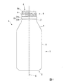
図1および図2は、本発明の第1の実施形態を示すものである。本実施形態のボトル缶において、その缶本体1は、底部2と、この底部2と一体に形成されて底部2の外周縁から上端側(図1および図2において上側)に延びる外周部3とを備えた缶軸Cを中心とする概略多段の有底円筒状をなしている。底部2には、缶軸C方向の内側(缶本体1の上端側)に凹む断面略円弧状のドーム部2aが中央に形成されるとともに、このドーム部2aの外周には缶軸C方向の外側(缶本体1の下端側)に突出する環状凸部2bが缶軸C回りの周方向に連続して形成されている(図5参照。)。
1 and 2 show a first embodiment of the present invention. In the bottle can of this embodiment, the
また、外周部3には底部2から缶本体1の上端側の開口部4に向けて順に、缶軸Cを中心とした円筒状の胴部5と、上端側に向かうに従い一定の傾斜で漸次縮径する円錐台面状の肩部6と、この肩部6からさらに上端側に向かって延びる筒状の首部7と、キャップ取付部8とが形成されている。このキャップ取付部8は、缶本体1を封止するキャップの雌ネジ部にねじ込まれる雄ネジ部9を上端側に備えるとともに、この雄ネジ部9よりも下端側には下方に向かう従い外周側に膨らんだ後に縮径して上記キャップの下端の開放端部が巻き締められる膨出部10を備えている。なお、キャップ取付部8の最上端部はカール部8aとされている。
In addition, the outer peripheral portion 3 has a
ここで、缶本体1の底部2の下端縁(環状凸部2bの下端縁)から外周部3の上端(カール部8aの上端縁)までの缶高さは、内容物の容量が310ml用のボトル缶の缶本体1では131.6mm〜133.6mm、内容物の容量が410ml用のボトル缶の缶本体1では163.0mm〜165.0mmとされる。また、缶本体1の外周部3における胴部5の直径は、ともに64.24mm〜68.24mmとされる。
Here, the can height from the lower end edge of the
このようなボトル缶を製造するには、まずカッピングプレス機によるカッピングプレス工程において、金属板を円板状に打ち抜いて絞り加工を施すことにより深さの浅いカップ状素材を製造する。このカッピングプレス工程においてカップ状素材に成形される金属板は、310ml用のボトル缶の缶本体1では元板厚が0.260mm〜0.310mm、410ml用のボトル缶の缶本体1では元板厚が0.310mm〜0.365mmのアルミニウム板またはJIS H 4000におけるA3004あるいはA3104のアルミニウム合金板であって、205℃×20分ベーキング後の0.2%耐力が235N/mm2〜265N/mm2の範囲のものが例えば用いられる。
In order to manufacture such a bottle can, first, in a cupping press process by a cupping press machine, a metal plate having a shallow depth is manufactured by punching a metal plate into a disk shape and performing a drawing process. The metal plate formed into a cup-shaped material in this cupping press process has a base plate thickness of 0.260 mm to 0.310 mm in the
次に、このカップ状素材にDIプレス機によるDIプレス工程において再絞りおよびしごき加工を施して缶軸C方向に延伸することにより、外周部に上記缶軸Cを中心とした円筒部が形成されるとともに、底部には缶本体1と同様のドーム部2aと環状凸部2bが形成された有底円筒体を成形する。この有底円筒体および缶本体1の底部2の厚さは、カッピングプレス工程においてカップ状素材に成形される金属板の元板厚と略等しい。
Next, the cup-shaped material is subjected to redrawing and ironing in a DI pressing process by a DI press machine and stretched in the direction of the can axis C, thereby forming a cylindrical portion around the can axis C on the outer periphery. In addition, a bottomed cylindrical body having a
また、この有底円筒体の上記円筒部は、その外径(直径)が缶本体1の胴部5の外径と略等しい一定外径とされる。さらに、この円筒部の底部側の部分は厚さ(肉厚)が薄くされた薄肉部であるウォール部とされるとともに、底部とは反対の上端側の部分は、ウォール部よりも厚さが厚くされた厚肉部であるフランジ部とされている。ここで、このような厚さの異なるウォール部とフランジ部とを円筒部に形成するには、上述のようにDIプレス機において複数のしごきダイスとの間でしごき加工を行うパンチの外表面のフランジ部と対応する位置に、肉厚の差を考慮した深さの凹部を形成しておけばよい。
The cylindrical portion of the bottomed cylindrical body has a constant outer diameter that is substantially equal to the outer diameter of the
また、このような有底円筒体においては、円筒部のウォール部のうち最薄部の厚さが0.100mm〜0.130mmの範囲とされるとともに、円筒部のうち最も厚肉となるフランジ部の厚さが0.160mm〜0.210mmとされる。さらに、このフランジ部とウォール部のうち最薄部との間の段差は0.090mm以下となるようにされ、0.070mm以下とされるのが望ましく、ただし0.045mm以上であることが望ましい。 In such a bottomed cylindrical body, the thickness of the thinnest portion of the wall portion of the cylindrical portion is in the range of 0.100 mm to 0.130 mm, and the flange that is the thickest of the cylindrical portion The thickness of the part is 0.160 mm to 0.210 mm. Further, the step between the flange portion and the thinnest portion of the wall portion is set to 0.090 mm or less, preferably 0.070 mm or less, but preferably 0.045 mm or more. .
このように成形された有底円筒体は、トリマーによるトリミング工程において円筒部の上端縁が所定のトリム代で切断されて高さが揃えられてから、第1の洗浄工程において洗浄、乾燥され、次に塗装工程において内外面に塗装が施されて焼き付けられる。さらに、塗装が施された有底円筒体は、ボトルネッカーによるボトルネック成形工程において、円筒部のうちフランジ部の範囲が縮径されて上記肩部6と首部7が成形される。
The bottomed cylindrical body formed in this manner is cleaned and dried in the first cleaning step after the upper edge of the cylindrical portion is cut at a predetermined trim margin in the trimming step by the trimmer and the height is aligned. Next, in the painting process, the inner and outer surfaces are painted and baked. Further, the bottomed cylindrical body to which the coating has been applied, in the bottle neck forming process by the bottle necker, the diameter of the flange portion of the cylindrical portion is reduced, and the
次いで、首部7の上端側が拡径されて上記膨出部10が形成されるとともに、この膨出部10よりも上端側にはスレッディング加工によって上記雄ネジ部9が形成され、雄ネジ部9よりも上端側部分が外周側に折り返されてカールされてからスロットル加工によって潰されて上記カール部8aとされることにより、キャップ取付部8が成形される。
Next, the upper end side of the
ここで、雄ネジ部9は、カール部8a側から平面視に時計回り方向に向かうに従い下端側に向かって捩れつつネジ山が不完全ネジ部において徐々に外周側に突出し、ネジ始まり部においてネジ山の左右の斜面が対称なネジとして有効に機能する完全ネジ部となる。さらに、雄ネジ部9は、この完全ネジ部においてネジ山が有効ネジ巻き数1巻以上(本実施形態では2.2巻)周回したところで内周側に徐々に後退して再び不完全ネジ部となる。このような雄ネジ部9の完全ネジ部におけるネジ谷の底からネジ山の頂点までのネジ高さは、例えば雄ネジ部9において最も外径の大きなネジ山のネジ谷部からネジ高さの50%以上とされる。
Here, the
また、上記膨出部10は、缶軸Cに沿った断面において凸曲線を描きつつ下方に向かうに従い外周側に膨らむ拡径部10aを上端側に備えるとともに、下端側にはこの拡径部10aの断面がなす凸曲線に滑らかに連なる断面凸曲線状をなして下方に向かうに従い縮径する縮径部10bを備えている。縮径部10bの断面がなす凸曲線は拡径部10aがなす凸曲線よりも曲率半径が小さく、この縮径部10bに上記キャップの開放端部が巻き締められる。ただし、拡径部10aは、缶軸Cに沿った断面において直線状に下方に向かうに従い外周側に膨らんでいてもよく、その缶軸Cに対する傾斜角は3°〜30°が好ましく、5°〜15°がより好ましい。このような角度範囲であれば、膨出部10の座屈強度が一層向上する。また、縮径部10bも、缶軸Cに沿った断面において直線状に下方に向かうに従い縮径していてもよく、その缶軸Cに対する傾斜角は40°〜50°が好ましい。このような角度範囲であれば、キャップの開放端部を裾巻きするのに適している。なお、この膨出部10における拡径部10aと縮径部10bとの境界、すなわち膨出部10の最大外径の位置における該膨出部10の缶軸Cに対する径方向の厚さtは、上述のような元板厚が薄肉化された金属板から成形されるボトル缶においては0.165mm〜0.220mmの範囲とされる。
Further, the bulging
そして、上記構成のボトル缶では、こうして成形された缶本体1の上記キャップ取付部8において、膨出部10は、缶軸Cに沿った断面が缶軸C回りの全周に亙って同一で、雄ネジ部9と缶軸C方向に分けられている。すなわち、雄ネジ部9の終端(下端)は、膨出部10に達することはなく、本実施形態では図1に示すように雄ネジ部9の上記終端におけるネジ山およびネジ谷と膨出部10の拡径部10aとの間には缶軸C方向に間隔があけられている。
And in the bottle can of the said structure, in the said
このように構成されたボトル缶においては、キャップ取付部8の雄ネジ部9が膨出部10に達することなく膨出部10と缶軸C方向に分けられており、膨出部10は缶軸Cに沿った断面が缶軸C回りの全周に亙って同一であるので、膨出部10の下方に向かって膨らむ拡径部10aの缶軸C方向の長さも全周に亙って均一であるとともに、この拡径部10aが缶軸Cに沿った断面で缶軸Cに対してなす傾斜角度も一定であり、従って膨出部10の缶軸C方向の座屈強度も缶軸C回りの全周に亙って均一とすることができる。
In the bottle can configured as described above, the
このため、拡径部10aの長さや傾斜角度、座屈強度の不均一により、キャッピングの際の絞り加工の荷重によってキャップ取付部8に局所的な座屈が生じるのを防ぐことができ、スカートローラーによって押圧してキャップの開放端部を膨出部10の縮径部10bに巻き締めする際に、このような局所的な座屈を起点として雄ネジ部9に変形が生じるのを防ぐことができる。従って、上述のようにボトル缶の缶本体1を薄肉化しても、このような雄ネジ部9の変形によって一旦取り外したキャップをリシールできなくなるような事態が生じたり、リシールトルクが増大したりするのを防ぐことができ、確実にキャップをリシールすることが可能となる。
For this reason, it is possible to prevent local buckling from occurring in the
また、本実施形態では、上述のように雄ネジ部9の終端におけるネジ山およびネジ谷と膨出部10の拡径部10aとの間に缶軸C方向に間隔があけられており、これにより一層確実に雄ネジ部9が膨出部10に到達して食い込むのを防ぐことができる。ただし、このように雄ネジ部9が膨出部10に食い込むことがなければ、雄ネジ部9の終端におけるネジ山およびネジ谷と膨出部10の拡径部10aとは接していてもよい。
Moreover, in this embodiment, the space | interval is opened in the can axis | shaft C direction between the screw thread and screw trough in the terminal end of the
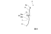
次に、図3および図4は、本発明の第2の実施形態を示すものであり、図1および図2に示した第1の実施形態と供給する部分には同一の符号を配して説明を省略する。この第2の実施形態においては、キャップ取付部8の雄ネジ部9と膨出部10との間に、キャップ取付部8の内周側に凹む凹部11が缶軸C回りの全周に亙って形成されていることを特徴とする。
Next, FIGS. 3 and 4 show the second embodiment of the present invention, and the same reference numerals are assigned to the parts to be supplied with the first embodiment shown in FIGS. Description is omitted. In the second embodiment, a
本実施形態における凹部11は、缶軸C方向において雄ネジ部9の終端から僅かに下端側に間隔をあけた位置から缶軸Cに沿った断面において凹曲線を描きつつ内周側に凹み始め、最も凹んだ位置を経た後に外周側に切れ上がって膨出部10の拡径部10aに交差している。この凹部11が缶軸Cに沿った断面においてなす凹曲線の曲率半径は、本実施形態では拡径部10aの断面がなす凸曲線の曲率半径よりも大きくされている。
In this embodiment, the
このように構成された第2の実施形態では、この凹部11によって雄ネジ部9と膨出部10とをさらに確実に缶軸C方向に分けることができ、雄ネジ部9が膨出部10に到達して食い込むのを防ぐことができる。また、こうして内周側に凹む凹部11が全周に亙って形成されることにより、キャップ取付部8の缶軸C方向への荷重に対する座屈強度を一層向上させることができる。
In the second embodiment configured as described above, the
さらに、図5および図6は、それぞれ本発明の第3、第4の実施形態を示すものであって、図1および図2に示した第1の実施形態と供給する部分にはやはり同一の符号を配して説明を省略する。これら第3、第4の実施形態においては、上記第1、第2の第1、第2の実施形態における雄ネジ部9の有効ネジ巻き数が2.2巻きであったのに対し、雄ネジ部9の有効ネジ巻き数が1.0巻き〜1.7巻きの範囲(例えば1.5巻き)とされていることを特徴とする。なお、図5に示す第3の実施形態では凹部11がなく、図6に示す第4の実施形態では雄ネジ部9と膨出部10との間に凹部11が形成されている。
Further, FIGS. 5 and 6 show third and fourth embodiments of the present invention, respectively, which are the same as those supplied in the first embodiment shown in FIGS. The reference numerals are assigned and the description is omitted. In the third and fourth embodiments, the effective screw winding number of the
このような第3、第4の実施形態では、有効ネジ巻き数が少ないので、雄ネジ部9の缶軸C方向の長さを短くすることができる。従って、キャップ取付部8や、このキャップ取付部8に取り付けられるキャップの缶軸C方向の長さも短くすることができるので、缶本体1の薄肉化と併せて、雄ネジ部9と膨出部10とを缶軸C方向に分けても、確実にボトル缶やキャップ付きボトル缶の軽量化を促すことが可能となる。
In such third and fourth embodiments, since the number of effective screw turns is small, the length of the
次に、本発明の実施例を挙げて本発明の効果について実証する。本実施例では、上記第1の実施形態に基づいて内容物の容量が410ml用のボトル缶として元板厚が0.365mm、円筒部におけるウォール部のうち最薄部の厚さが0.120mm、フランジ部の厚さが0.165mmの有底円筒体(DI缶)から缶高さ165.0mm、胴部の外径が66.0mmのボトル缶を20缶成形した。これらの実施例のボトル缶の有効ネジ巻き数は2.2巻き、膨出部10の缶軸C方向の長さは6.25mmで缶軸C回りの全周で同一の寸法、形状であった。
Next, the effect of the present invention will be demonstrated with examples of the present invention. In this example, the base plate thickness is 0.365 mm as a bottle can with a capacity of 410 ml based on the first embodiment, and the thickness of the thinnest portion of the wall portion in the cylindrical portion is 0.120 mm. From the bottomed cylindrical body (DI can) having a flange portion thickness of 0.165 mm, 20 cans having a can height of 165.0 mm and a barrel portion having an outer diameter of 66.0 mm were molded. The number of effective screw windings of the bottle cans of these examples is 2.2, the length of the bulging
また、この実施例に対する比較例として、キャップ取付部以外は実施例と同一の寸法形状、有効ネジ巻き数で、雄ネジ部が膨出部に到達していて、膨出部の缶軸方向の長さが最長で6.25mm、最短で3.3mmとなる従来のボトル缶を薄肉化したものも20缶成形した。この比較例のボトル缶では、雄ネジ部の終端におけるネジ谷部が膨出部に達していて、このネジ谷の終端付近が膨出部の缶軸方向最短の位置となる。なお、これら実施例と比較例の膨出部の最大外径の位置における膨出部の缶軸に対する径方向の厚さtは、いずれも平均で0.170mmであった。 In addition, as a comparative example for this embodiment, the male screw portion reaches the bulging portion with the same dimensions and shape as the embodiment except for the cap mounting portion, and the number of effective screw turns, and the bulging portion in the can axis direction 20 cans were formed by thinning a conventional bottle can having a maximum length of 6.25 mm and a minimum length of 3.3 mm. In the bottle can of this comparative example, the thread valley at the end of the male thread reaches the bulge, and the vicinity of the end of the thread is the shortest position in the can axis direction of the bulge. In addition, the thickness t in the radial direction with respect to the can shaft of the bulging portion at the position of the maximum outer diameter of the bulging portion in these examples and comparative examples was 0.170 mm on average.
そして、これら実施例と比較例のボトル缶で、缶軸C方向の荷重1000Nで絞り加工を行うとともに、缶軸Cに垂直な方向にスレッドローラーによる先端荷重130N、スカートローラーによる先端荷重100Nでキャッピングを行った後、キャップを一旦取り外してから再び雄ネジ部にねじ込んで、元の位置よりも手前に30°まで戻してリシールしたときに要した最大リシールトルクを測定した。 The bottle cans of these examples and comparative examples are drawn with a load of 1000 N in the direction of the can axis C and capped with a tip load of 130 N by a thread roller and a tip load of 100 N by a skirt roller in a direction perpendicular to the can axis C. After the cap was removed, the cap was once removed and screwed into the male threaded portion again, and the maximum resealing torque required when resealing by returning to 30 ° before the original position was measured.
その結果、比較例のボトル缶では、20缶中17缶では上記リシールトルクは0Nであったものの、1缶では50.0Nのリシールトルクを要し、他の1缶では80.0Nのリシールトルクを要し、さらに残りの1缶では雄ネジ部の変形によってリシール自体が不可能であった。これに対して本発明に基づく実施例のボトル缶では、20缶いずれもリシールトルクは0Nで、軽快なリシールが可能であった。 As a result, in the bottles of the comparative example, the reseal torque was 17N in 20 cans, but the reseal torque of 50.0N was required in one can, and the reseal torque of 80.0N in the other can. In the remaining one can, resealing itself was impossible due to deformation of the male screw portion. On the other hand, in the bottle cans of the examples based on the present invention, the reseal torque of all 20 cans was 0 N, and light reseal was possible.
1 缶本体
2 底部
3 外周部
4 開口部
5 胴部
6 肩部
7 首部
8 キャップ取付部
8a カール部
9 雄ネジ部
10 膨出部
10a 拡径部
10b 縮径部
C 缶軸
DESCRIPTION OF
Claims (3)
上記キャップ取付部は、上端側に上記キャップの雌ネジ部にねじ込まれる雄ネジ部を備えるとともに、下端側には下方に向かう従い外周側に膨らんだ後に縮径して上記キャップの下端の開放端部が巻き締められる膨出部を備え、
上記膨出部は、上記缶軸に沿った断面が該缶軸回りの全周に亙って同一で、上記雄ネジ部と上記缶軸方向に分けられていることを特徴とするボトル缶。 A metal bottle can in which a cylindrical cap attachment portion to which a cap is attached is formed at the upper end portion of a bottomed cylindrical can body centering on a can axis,
The cap mounting portion includes a male screw portion that is screwed into the female screw portion of the cap on the upper end side, and is reduced in diameter after being bulged toward the outer peripheral side toward the lower end side, and is opened at the lower end of the cap. It has a bulging part where the part is wound,
The bottle can characterized in that the bulging portion has the same cross-section along the can axis over the entire circumference of the can axis and is divided in the male screw portion and the can axis direction.
Priority Applications (1)
| Application Number | Priority Date | Filing Date | Title |
|---|---|---|---|
| JP2017059127A JP2018162071A (en) | 2017-03-24 | 2017-03-24 | Bottle can |
Applications Claiming Priority (1)
| Application Number | Priority Date | Filing Date | Title |
|---|---|---|---|
| JP2017059127A JP2018162071A (en) | 2017-03-24 | 2017-03-24 | Bottle can |
Related Child Applications (2)
| Application Number | Title | Priority Date | Filing Date |
|---|---|---|---|
| JP2018118318A Division JP6478438B2 (en) | 2018-06-21 | 2018-06-21 | Bottle can |
| JP2019155932A Division JP7262344B2 (en) | 2019-08-28 | 2019-08-28 | bottle can |
Publications (2)
| Publication Number | Publication Date |
|---|---|
| JP2018162071A true JP2018162071A (en) | 2018-10-18 |
| JP2018162071A5 JP2018162071A5 (en) | 2019-02-21 |
Family
ID=63859579
Family Applications (1)
| Application Number | Title | Priority Date | Filing Date |
|---|---|---|---|
| JP2017059127A Pending JP2018162071A (en) | 2017-03-24 | 2017-03-24 | Bottle can |
Country Status (1)
| Country | Link |
|---|---|
| JP (1) | JP2018162071A (en) |
Citations (11)
| Publication number | Priority date | Publication date | Assignee | Title |
|---|---|---|---|---|
| JP2003205945A (en) * | 2002-01-17 | 2003-07-22 | Mitsubishi Materials Corp | Metal bottle can and method for producing it |
| JP2004074170A (en) * | 2002-08-09 | 2004-03-11 | Mitsubishi Materials Corp | Bottle can screw-forming device and bottle can |
| JP2004338759A (en) * | 2003-05-15 | 2004-12-02 | Mitsubishi Materials Corp | Cap, bottle having cap, and method of releasing inner pressure of bottle having cap |
| JP2006176183A (en) * | 2004-12-24 | 2006-07-06 | Mitsubishi Materials Corp | Bottle can and manufacturing method of the same |
| JP2007297140A (en) * | 1994-11-22 | 2007-11-15 | Alcoa Inc | Aluminum can with screw and method for manufacturing the same |
| JP2008087071A (en) * | 2007-12-10 | 2008-04-17 | Universal Seikan Kk | Method and device for forming mouth portion of metal bottle body, and metal bottle body and capped metal bottle |
| JP2013510778A (en) * | 2009-11-13 | 2013-03-28 | ザ コカ・コーラ カンパニー | Molded metal container |
| JP2015511562A (en) * | 2012-03-15 | 2015-04-20 | アルダフ エムピー グループ ネザーランド ベー.ヴェー. | Metal package with tubular part |
| JP2016036843A (en) * | 2014-08-08 | 2016-03-22 | ユニバーサル製缶株式会社 | Method and apparatus for manufacturing bottle can with screw |
| US20160251104A1 (en) * | 2013-07-24 | 2016-09-01 | Alpha Consolidated Holdings Inc. | Bottle with expansion chamber and pinch grips |
| JP2016196332A (en) * | 2015-04-06 | 2016-11-24 | 武内プレス工業株式会社 | Screwed metal container |
-
2017
- 2017-03-24 JP JP2017059127A patent/JP2018162071A/en active Pending
Patent Citations (12)
| Publication number | Priority date | Publication date | Assignee | Title |
|---|---|---|---|---|
| JP2007297140A (en) * | 1994-11-22 | 2007-11-15 | Alcoa Inc | Aluminum can with screw and method for manufacturing the same |
| JP2003205945A (en) * | 2002-01-17 | 2003-07-22 | Mitsubishi Materials Corp | Metal bottle can and method for producing it |
| JP2004074170A (en) * | 2002-08-09 | 2004-03-11 | Mitsubishi Materials Corp | Bottle can screw-forming device and bottle can |
| JP2004338759A (en) * | 2003-05-15 | 2004-12-02 | Mitsubishi Materials Corp | Cap, bottle having cap, and method of releasing inner pressure of bottle having cap |
| JP2006176183A (en) * | 2004-12-24 | 2006-07-06 | Mitsubishi Materials Corp | Bottle can and manufacturing method of the same |
| JP2008087071A (en) * | 2007-12-10 | 2008-04-17 | Universal Seikan Kk | Method and device for forming mouth portion of metal bottle body, and metal bottle body and capped metal bottle |
| JP2013510778A (en) * | 2009-11-13 | 2013-03-28 | ザ コカ・コーラ カンパニー | Molded metal container |
| JP2017019567A (en) * | 2009-11-13 | 2017-01-26 | ザ コカ・コーラ カンパニーThe Coca‐Cola Company | Shaped metal vessel |
| JP2015511562A (en) * | 2012-03-15 | 2015-04-20 | アルダフ エムピー グループ ネザーランド ベー.ヴェー. | Metal package with tubular part |
| US20160251104A1 (en) * | 2013-07-24 | 2016-09-01 | Alpha Consolidated Holdings Inc. | Bottle with expansion chamber and pinch grips |
| JP2016036843A (en) * | 2014-08-08 | 2016-03-22 | ユニバーサル製缶株式会社 | Method and apparatus for manufacturing bottle can with screw |
| JP2016196332A (en) * | 2015-04-06 | 2016-11-24 | 武内プレス工業株式会社 | Screwed metal container |
Similar Documents
| Publication | Publication Date | Title |
|---|---|---|
| US11130607B2 (en) | Bottle can, bottle can with cap, and method for manufacturing bottle can | |
| CN210618740U (en) | Bottle-shaped can with lid and apparatus for manufacturing the same | |
| JP6817106B2 (en) | Bottle type can | |
| JP6877943B2 (en) | How to make bottle cans | |
| JP7206046B2 (en) | Bottle can and method for manufacturing bottle can | |
| JP6478438B2 (en) | Bottle can | |
| JP2019199307A (en) | Bottle can | |
| JP2018162071A (en) | Bottle can | |
| JP2018131261A (en) | Manufacturing method for bottle can | |
| JP7220983B2 (en) | bottle can, bottle can with cap | |
| JP7072380B2 (en) | How to make a bottle can | |
| US11440695B2 (en) | Method for manufacturing metal bottle, and metal bottle | |
| JP2018193137A (en) | Bottle can, bottle can with cap and production method of bottle can | |
| JP2018104096A (en) | Bottle can and bottle can with cap | |
| JP2018154407A (en) | Production method of bottle can | |
| WO2019039184A1 (en) | Bottle-shaped can and capped bottle-shaped can | |
| JP2018103254A (en) | Bottle can, capped bottle can, and manufacturing method for the same | |
| JP2019111554A (en) | Method for manufacturing bottle can | |
| JP6496868B1 (en) | Manufacturing method for bottle cans | |
| JP2023102644A (en) | Bottle-shape can, and roughly-shaped material for bottle-shape can | |
| JP2005014942A (en) | Cap and bottle can with cap | |
| JP2022177092A (en) | Bottle can body, bottle can body with cap, method for capping bottle can body | |
| JP2019112081A (en) | Bottle can, capped bottle can and manufacturing method for bottle can | |
| JP2020152445A (en) | Bottle can and manufacturing method the same | |
| JP2018131262A (en) | Cap for bottle can, bottle can, and method of capping bottle can with cap for bottle can |
Legal Events
| Date | Code | Title | Description |
|---|---|---|---|
| RD03 | Notification of appointment of power of attorney |
Free format text: JAPANESE INTERMEDIATE CODE: A7423 Effective date: 20181026 |
|
| A521 | Request for written amendment filed |
Free format text: JAPANESE INTERMEDIATE CODE: A523 Effective date: 20190109 |
|
| A621 | Written request for application examination |
Free format text: JAPANESE INTERMEDIATE CODE: A621 Effective date: 20190109 |
|
| A871 | Explanation of circumstances concerning accelerated examination |
Free format text: JAPANESE INTERMEDIATE CODE: A871 Effective date: 20190109 |
|
| A975 | Report on accelerated examination |
Free format text: JAPANESE INTERMEDIATE CODE: A971005 Effective date: 20190128 |
|
| A131 | Notification of reasons for refusal |
Free format text: JAPANESE INTERMEDIATE CODE: A131 Effective date: 20190219 |
|
| A521 | Request for written amendment filed |
Free format text: JAPANESE INTERMEDIATE CODE: A523 Effective date: 20190411 |
|
| A131 | Notification of reasons for refusal |
Free format text: JAPANESE INTERMEDIATE CODE: A131 Effective date: 20190716 |
|
| A521 | Request for written amendment filed |
Free format text: JAPANESE INTERMEDIATE CODE: A523 Effective date: 20190828 |
|
| A02 | Decision of refusal |
Free format text: JAPANESE INTERMEDIATE CODE: A02 Effective date: 20191029 |