JP2013507533A5 - - Google Patents
Download PDFInfo
- Publication number
- JP2013507533A5 JP2013507533A5 JP2012532436A JP2012532436A JP2013507533A5 JP 2013507533 A5 JP2013507533 A5 JP 2013507533A5 JP 2012532436 A JP2012532436 A JP 2012532436A JP 2012532436 A JP2012532436 A JP 2012532436A JP 2013507533 A5 JP2013507533 A5 JP 2013507533A5
- Authority
- JP
- Japan
- Prior art keywords
- guide element
- combing machine
- machine according
- combing
- sliver
- Prior art date
- Legal status (The legal status is an assumption and is not a legal conclusion. Google has not performed a legal analysis and makes no representation as to the accuracy of the status listed.)
- Pending
Links
- 230000001154 acute Effects 0.000 claims 1
- 238000005452 bending Methods 0.000 claims 1
- 239000000969 carrier Substances 0.000 claims 1
- 239000000835 fiber Substances 0.000 claims 1
Images
Claims (15)
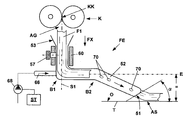
各プレスローラ対(K)と搬送テーブル(T)との間に、プレスローラ対(K)から排出されたスライバ(F1)のためのガイドエレメント(FE)が設けられており、該ガイドエレメント(FE)は、規定された軌道においてスライバ(F1)を正確に案内するため及び搬送テーブル(T)上に位置正確に排出するために形成されていることを特徴とするコーミング機械。 Combing machine comprising a plurality of combing heads (K1 to Kx) arranged side by side, provided with means (33, 39) provided with combed fiber fleece (V) formed in the individual combing heads ) Are combined into one sliver (F1), supplied to the press roller pair (K), and then discharged onto the transfer table (T), on which the sliver (F1) is adjacent. In a type in which the other slivers (F2 to Fx) discharged in the arranged combing head are arranged next to each other and supplied to the subsequent draft device (D) as one sliver complex (FV) ,
Between each pair of press rollers (K) and the conveying table (T), the guide element (FE) is provided for the sliver discharged from the pair of press rollers (K) (F1), said guide element ( Combing machine characterized in that FE) is formed in order to accurately guide the sliver (F1) in a defined trajectory and to accurately eject the sliver on the transfer table (T) .
Applications Claiming Priority (3)
| Application Number | Priority Date | Filing Date | Title |
|---|---|---|---|
| CH01553/09A CH702008A2 (en) | 2009-10-08 | 2009-10-08 | Comber sliver with guide means. |
| CH1553/09 | 2009-10-08 | ||
| PCT/CH2010/000241 WO2011041919A1 (en) | 2009-10-08 | 2010-10-04 | Combing machine having a sliver-guiding means |
Publications (2)
| Publication Number | Publication Date |
|---|---|
| JP2013507533A JP2013507533A (en) | 2013-03-04 |
| JP2013507533A5 true JP2013507533A5 (en) | 2013-11-21 |
Family
ID=43478412
Family Applications (1)
| Application Number | Title | Priority Date | Filing Date |
|---|---|---|---|
| JP2012532436A Pending JP2013507533A (en) | 2009-10-08 | 2010-10-04 | Combing machine with sliver guide means |
Country Status (5)
| Country | Link |
|---|---|
| EP (1) | EP2486176B1 (en) |
| JP (1) | JP2013507533A (en) |
| CN (1) | CN102549205B (en) |
| CH (1) | CH702008A2 (en) |
| WO (1) | WO2011041919A1 (en) |
Families Citing this family (4)
| Publication number | Priority date | Publication date | Assignee | Title |
|---|---|---|---|---|
| PL2354343T3 (en) | 2010-02-10 | 2014-12-31 | Ruwa Drahtschweisswerk Ag | Cantilever plate connecting element / pressure elements |
| CH709311A2 (en) | 2014-02-27 | 2015-08-28 | Rieter Ag Maschf | An apparatus for forming a nonwoven fabric made of fiber packets. |
| DE102018122276B4 (en) * | 2018-09-12 | 2021-02-11 | TRüTZSCHLER GMBH & CO. KG | Comber |
| DE102020115191A1 (en) | 2020-06-08 | 2021-12-09 | Trützschler GmbH & Co Kommanditgesellschaft | Comber |
Family Cites Families (12)
| Publication number | Priority date | Publication date | Assignee | Title |
|---|---|---|---|---|
| JPS5112493Y1 (en) * | 1968-03-18 | 1976-04-05 | ||
| JPS513809B1 (en) * | 1968-08-14 | 1976-02-06 | ||
| GB1271316A (en) * | 1969-04-21 | 1972-04-19 | Osaka Kiko Kabushiki Kaisha | An improved method and apparatus for producing combed sliver |
| JPH0456768U (en) * | 1990-09-14 | 1992-05-15 | ||
| DE10127814A1 (en) * | 2001-06-07 | 2002-12-12 | Truetzschler Gmbh & Co Kg | Turntable for fibre band release unit for drafting or carding assembly discharges fibre through sickle-shaped tube with air cushion between fibre and tube |
| CN2552957Y (en) * | 2002-05-10 | 2003-05-28 | 郑伟东 | Combing machine table-top delivery apparatus |
| CN1510183A (en) * | 2002-12-23 | 2004-07-07 | 倪 远 | Method and device for combining carding, combing and drawing |
| DE102005001241A1 (en) * | 2004-02-19 | 2005-09-01 | Maschinenfabrik Rieter Ag | Textile machine fleece combing station has calender with moving drum and swivel-mounted moving drum |
| CN2813644Y (en) * | 2005-08-09 | 2006-09-06 | 东台纺织机械有限责任公司 | Comber cotton-fleece guiding device |
| EP2044249B1 (en) * | 2006-07-25 | 2011-06-15 | Maschinenfabrik Rieter Ag | Combing machine |
| CN101495686B (en) * | 2006-07-25 | 2011-04-06 | 里特机械公司 | Combing machine |
| DE102007045706A1 (en) * | 2007-09-24 | 2009-04-02 | TRüTZSCHLER GMBH & CO. KG | Comber, has combing head including one-piece stretching unit, silver depositing device including rotatable tube wheel, and individual strut attached to support having movable upper surface with respect to belt guide |
-
2009
- 2009-10-08 CH CH01553/09A patent/CH702008A2/en not_active Application Discontinuation
-
2010
- 2010-10-04 CN CN201080045250.7A patent/CN102549205B/en not_active Expired - Fee Related
- 2010-10-04 EP EP10767907.8A patent/EP2486176B1/en not_active Not-in-force
- 2010-10-04 WO PCT/CH2010/000241 patent/WO2011041919A1/en active Application Filing
- 2010-10-04 JP JP2012532436A patent/JP2013507533A/en active Pending
Similar Documents
| Publication | Publication Date | Title |
|---|---|---|
| CN101333706B (en) | Apparatus for the sorting or selection of a fibre sliver comprising textile fibres | |
| JP2013507533A5 (en) | ||
| CN104200581B (en) | Correction correcting unit and ATM | |
| JP2009013570A5 (en) | ||
| ITMI20081136A1 (en) | EQUIPMENT FOR THE FIBER SORTING OR THE FIBER SELECTION OF A FIBER BAND INCLUDING TEXTILE FIBERS, ESPECIALLY FOR COMBING | |
| JP2009013560A5 (en) | ||
| CN101799886A (en) | Counting and combining device | |
| CN104372452A (en) | Cleaner for fiber bundle feeder in fore-spinning frame | |
| CN104153054A (en) | Draw frame and lap machine combine | |
| CN107119352B (en) | Winding machine for winding slivers into lap | |
| CN102094266B (en) | Air suction pipe for yarn strip bundling device for spinning device and method for manufacturing the same | |
| US9725830B2 (en) | Device for conveying a fiber web or a web of nonwoven | |
| JP2008081320A5 (en) | ||
| CN205076523U (en) | Cloth rolling machine | |
| CN104928814B (en) | Fibre controlling part part, drafting system and spinning machinery | |
| RU2014153635A (en) | REWINDER | |
| JP2018035463A5 (en) | ||
| EP1783253A3 (en) | Fiber bundle concentrating device in spinning machine and method for manufacturing perforated belt | |
| JP2014530965A5 (en) | ||
| JP5883608B2 (en) | Modular plastic belt conveyor drive | |
| CN204206783U (en) | Cotton harvester | |
| ITBS20130120A1 (en) | COMPACTION DEVICE OF A TAPE OF FIBER TEXTILE IN A FILATOIO | |
| CN106239952A (en) | Shoulder wedge feeding system | |
| CN202809056U (en) | Strip guiding device of lap former | |
| JP2009114583A5 (en) |