JP2013504147A - Electrochemical energy storage device for vehicles and method for cooling or heating such electrochemical energy storage device - Google Patents
Electrochemical energy storage device for vehicles and method for cooling or heating such electrochemical energy storage device Download PDFInfo
- Publication number
- JP2013504147A JP2013504147A JP2012527222A JP2012527222A JP2013504147A JP 2013504147 A JP2013504147 A JP 2013504147A JP 2012527222 A JP2012527222 A JP 2012527222A JP 2012527222 A JP2012527222 A JP 2012527222A JP 2013504147 A JP2013504147 A JP 2013504147A
- Authority
- JP
- Japan
- Prior art keywords
- heat
- storage device
- energy storage
- flat
- electrochemical energy
- Prior art date
- Legal status (The legal status is an assumption and is not a legal conclusion. Google has not performed a legal analysis and makes no representation as to the accuracy of the status listed.)
- Pending
Links
Images


Classifications
-
- H—ELECTRICITY
- H01—ELECTRIC ELEMENTS
- H01M—PROCESSES OR MEANS, e.g. BATTERIES, FOR THE DIRECT CONVERSION OF CHEMICAL ENERGY INTO ELECTRICAL ENERGY
- H01M10/00—Secondary cells; Manufacture thereof
- H01M10/60—Heating or cooling; Temperature control
- H01M10/65—Means for temperature control structurally associated with the cells
- H01M10/655—Solid structures for heat exchange or heat conduction
- H01M10/6556—Solid parts with flow channel passages or pipes for heat exchange
- H01M10/6557—Solid parts with flow channel passages or pipes for heat exchange arranged between the cells
-
- H—ELECTRICITY
- H01—ELECTRIC ELEMENTS
- H01M—PROCESSES OR MEANS, e.g. BATTERIES, FOR THE DIRECT CONVERSION OF CHEMICAL ENERGY INTO ELECTRICAL ENERGY
- H01M10/00—Secondary cells; Manufacture thereof
- H01M10/60—Heating or cooling; Temperature control
- H01M10/61—Types of temperature control
- H01M10/613—Cooling or keeping cold
-
- H—ELECTRICITY
- H01—ELECTRIC ELEMENTS
- H01M—PROCESSES OR MEANS, e.g. BATTERIES, FOR THE DIRECT CONVERSION OF CHEMICAL ENERGY INTO ELECTRICAL ENERGY
- H01M10/00—Secondary cells; Manufacture thereof
- H01M10/04—Construction or manufacture in general
- H01M10/0413—Large-sized flat cells or batteries for motive or stationary systems with plate-like electrodes
-
- H—ELECTRICITY
- H01—ELECTRIC ELEMENTS
- H01M—PROCESSES OR MEANS, e.g. BATTERIES, FOR THE DIRECT CONVERSION OF CHEMICAL ENERGY INTO ELECTRICAL ENERGY
- H01M10/00—Secondary cells; Manufacture thereof
- H01M10/04—Construction or manufacture in general
- H01M10/0436—Small-sized flat cells or batteries for portable equipment
-
- H—ELECTRICITY
- H01—ELECTRIC ELEMENTS
- H01M—PROCESSES OR MEANS, e.g. BATTERIES, FOR THE DIRECT CONVERSION OF CHEMICAL ENERGY INTO ELECTRICAL ENERGY
- H01M10/00—Secondary cells; Manufacture thereof
- H01M10/05—Accumulators with non-aqueous electrolyte
- H01M10/052—Li-accumulators
- H01M10/0525—Rocking-chair batteries, i.e. batteries with lithium insertion or intercalation in both electrodes; Lithium-ion batteries
-
- H—ELECTRICITY
- H01—ELECTRIC ELEMENTS
- H01M—PROCESSES OR MEANS, e.g. BATTERIES, FOR THE DIRECT CONVERSION OF CHEMICAL ENERGY INTO ELECTRICAL ENERGY
- H01M10/00—Secondary cells; Manufacture thereof
- H01M10/60—Heating or cooling; Temperature control
- H01M10/61—Types of temperature control
- H01M10/615—Heating or keeping warm
-
- H—ELECTRICITY
- H01—ELECTRIC ELEMENTS
- H01M—PROCESSES OR MEANS, e.g. BATTERIES, FOR THE DIRECT CONVERSION OF CHEMICAL ENERGY INTO ELECTRICAL ENERGY
- H01M10/00—Secondary cells; Manufacture thereof
- H01M10/60—Heating or cooling; Temperature control
- H01M10/62—Heating or cooling; Temperature control specially adapted for specific applications
- H01M10/625—Vehicles
-
- H—ELECTRICITY
- H01—ELECTRIC ELEMENTS
- H01M—PROCESSES OR MEANS, e.g. BATTERIES, FOR THE DIRECT CONVERSION OF CHEMICAL ENERGY INTO ELECTRICAL ENERGY
- H01M10/00—Secondary cells; Manufacture thereof
- H01M10/60—Heating or cooling; Temperature control
- H01M10/63—Control systems
- H01M10/633—Control systems characterised by algorithms, flow charts, software details or the like
-
- H—ELECTRICITY
- H01—ELECTRIC ELEMENTS
- H01M—PROCESSES OR MEANS, e.g. BATTERIES, FOR THE DIRECT CONVERSION OF CHEMICAL ENERGY INTO ELECTRICAL ENERGY
- H01M10/00—Secondary cells; Manufacture thereof
- H01M10/60—Heating or cooling; Temperature control
- H01M10/64—Heating or cooling; Temperature control characterised by the shape of the cells
- H01M10/647—Prismatic or flat cells, e.g. pouch cells
-
- H—ELECTRICITY
- H01—ELECTRIC ELEMENTS
- H01M—PROCESSES OR MEANS, e.g. BATTERIES, FOR THE DIRECT CONVERSION OF CHEMICAL ENERGY INTO ELECTRICAL ENERGY
- H01M10/00—Secondary cells; Manufacture thereof
- H01M10/60—Heating or cooling; Temperature control
- H01M10/65—Means for temperature control structurally associated with the cells
- H01M10/655—Solid structures for heat exchange or heat conduction
- H01M10/6551—Surfaces specially adapted for heat dissipation or radiation, e.g. fins or coatings
-
- H—ELECTRICITY
- H01—ELECTRIC ELEMENTS
- H01M—PROCESSES OR MEANS, e.g. BATTERIES, FOR THE DIRECT CONVERSION OF CHEMICAL ENERGY INTO ELECTRICAL ENERGY
- H01M10/00—Secondary cells; Manufacture thereof
- H01M10/60—Heating or cooling; Temperature control
- H01M10/65—Means for temperature control structurally associated with the cells
- H01M10/655—Solid structures for heat exchange or heat conduction
- H01M10/6554—Rods or plates
- H01M10/6555—Rods or plates arranged between the cells
-
- H—ELECTRICITY
- H01—ELECTRIC ELEMENTS
- H01M—PROCESSES OR MEANS, e.g. BATTERIES, FOR THE DIRECT CONVERSION OF CHEMICAL ENERGY INTO ELECTRICAL ENERGY
- H01M50/00—Constructional details or processes of manufacture of the non-active parts of electrochemical cells other than fuel cells, e.g. hybrid cells
- H01M50/10—Primary casings, jackets or wrappings of a single cell or a single battery
- H01M50/116—Primary casings, jackets or wrappings of a single cell or a single battery characterised by the material
-
- H—ELECTRICITY
- H01—ELECTRIC ELEMENTS
- H01M—PROCESSES OR MEANS, e.g. BATTERIES, FOR THE DIRECT CONVERSION OF CHEMICAL ENERGY INTO ELECTRICAL ENERGY
- H01M50/00—Constructional details or processes of manufacture of the non-active parts of electrochemical cells other than fuel cells, e.g. hybrid cells
- H01M50/20—Mountings; Secondary casings or frames; Racks, modules or packs; Suspension devices; Shock absorbers; Transport or carrying devices; Holders
- H01M50/204—Racks, modules or packs for multiple batteries or multiple cells
- H01M50/207—Racks, modules or packs for multiple batteries or multiple cells characterised by their shape
- H01M50/209—Racks, modules or packs for multiple batteries or multiple cells characterised by their shape adapted for prismatic or rectangular cells
-
- H—ELECTRICITY
- H01—ELECTRIC ELEMENTS
- H01M—PROCESSES OR MEANS, e.g. BATTERIES, FOR THE DIRECT CONVERSION OF CHEMICAL ENERGY INTO ELECTRICAL ENERGY
- H01M50/00—Constructional details or processes of manufacture of the non-active parts of electrochemical cells other than fuel cells, e.g. hybrid cells
- H01M50/20—Mountings; Secondary casings or frames; Racks, modules or packs; Suspension devices; Shock absorbers; Transport or carrying devices; Holders
- H01M50/258—Modular batteries; Casings provided with means for assembling
-
- H—ELECTRICITY
- H01—ELECTRIC ELEMENTS
- H01M—PROCESSES OR MEANS, e.g. BATTERIES, FOR THE DIRECT CONVERSION OF CHEMICAL ENERGY INTO ELECTRICAL ENERGY
- H01M50/00—Constructional details or processes of manufacture of the non-active parts of electrochemical cells other than fuel cells, e.g. hybrid cells
- H01M50/20—Mountings; Secondary casings or frames; Racks, modules or packs; Suspension devices; Shock absorbers; Transport or carrying devices; Holders
- H01M50/289—Mountings; Secondary casings or frames; Racks, modules or packs; Suspension devices; Shock absorbers; Transport or carrying devices; Holders characterised by spacing elements or positioning means within frames, racks or packs
- H01M50/291—Mountings; Secondary casings or frames; Racks, modules or packs; Suspension devices; Shock absorbers; Transport or carrying devices; Holders characterised by spacing elements or positioning means within frames, racks or packs characterised by their shape
-
- H—ELECTRICITY
- H01—ELECTRIC ELEMENTS
- H01M—PROCESSES OR MEANS, e.g. BATTERIES, FOR THE DIRECT CONVERSION OF CHEMICAL ENERGY INTO ELECTRICAL ENERGY
- H01M50/00—Constructional details or processes of manufacture of the non-active parts of electrochemical cells other than fuel cells, e.g. hybrid cells
- H01M50/50—Current conducting connections for cells or batteries
- H01M50/543—Terminals
- H01M50/552—Terminals characterised by their shape
- H01M50/553—Terminals adapted for prismatic, pouch or rectangular cells
- H01M50/557—Plate-shaped terminals
-
- H—ELECTRICITY
- H01—ELECTRIC ELEMENTS
- H01M—PROCESSES OR MEANS, e.g. BATTERIES, FOR THE DIRECT CONVERSION OF CHEMICAL ENERGY INTO ELECTRICAL ENERGY
- H01M6/00—Primary cells; Manufacture thereof
- H01M6/50—Methods or arrangements for servicing or maintenance, e.g. for maintaining operating temperature
- H01M6/5038—Heating or cooling of cells or batteries
-
- H—ELECTRICITY
- H01—ELECTRIC ELEMENTS
- H01M—PROCESSES OR MEANS, e.g. BATTERIES, FOR THE DIRECT CONVERSION OF CHEMICAL ENERGY INTO ELECTRICAL ENERGY
- H01M2220/00—Batteries for particular applications
- H01M2220/20—Batteries in motive systems, e.g. vehicle, ship, plane
-
- Y—GENERAL TAGGING OF NEW TECHNOLOGICAL DEVELOPMENTS; GENERAL TAGGING OF CROSS-SECTIONAL TECHNOLOGIES SPANNING OVER SEVERAL SECTIONS OF THE IPC; TECHNICAL SUBJECTS COVERED BY FORMER USPC CROSS-REFERENCE ART COLLECTIONS [XRACs] AND DIGESTS
- Y02—TECHNOLOGIES OR APPLICATIONS FOR MITIGATION OR ADAPTATION AGAINST CLIMATE CHANGE
- Y02E—REDUCTION OF GREENHOUSE GAS [GHG] EMISSIONS, RELATED TO ENERGY GENERATION, TRANSMISSION OR DISTRIBUTION
- Y02E60/00—Enabling technologies; Technologies with a potential or indirect contribution to GHG emissions mitigation
- Y02E60/10—Energy storage using batteries
-
- Y—GENERAL TAGGING OF NEW TECHNOLOGICAL DEVELOPMENTS; GENERAL TAGGING OF CROSS-SECTIONAL TECHNOLOGIES SPANNING OVER SEVERAL SECTIONS OF THE IPC; TECHNICAL SUBJECTS COVERED BY FORMER USPC CROSS-REFERENCE ART COLLECTIONS [XRACs] AND DIGESTS
- Y02—TECHNOLOGIES OR APPLICATIONS FOR MITIGATION OR ADAPTATION AGAINST CLIMATE CHANGE
- Y02P—CLIMATE CHANGE MITIGATION TECHNOLOGIES IN THE PRODUCTION OR PROCESSING OF GOODS
- Y02P70/00—Climate change mitigation technologies in the production process for final industrial or consumer products
- Y02P70/50—Manufacturing or production processes characterised by the final manufactured product
Abstract
電気化学的エネルギー貯蔵装置(1)は、複数の平型ガルバニセル(3)が設けられているハウジング(2)を備える。隣り合う2つの平型ガルバニセルの間に、それぞれ1つの平型熱伝導体(4)および/あるいは平型弾性体(5)が設けられている。好適には、平型ガルバニセル、平型熱伝導体および/あるいは平型弾性体が、接触面で、面圧の意味での力(11)を互いにかけ合い、熱伝導体(4)が、当該熱伝導体が接触面で作用する力(11)の方向に移動できないように係合する、1つの構造体あるいは複数の構造体(8,9)を有する壁をハウジングが備える。 The electrochemical energy storage device (1) comprises a housing (2) provided with a plurality of flat galvanic cells (3). One flat heat conductor (4) and / or flat elastic body (5) is provided between two adjacent flat galvanic cells. Preferably, the flat galvanic cell, the flat heat conductor and / or the flat elastic body apply a force (11) in the sense of surface pressure to each other at the contact surface, and the heat conductor (4) The housing comprises a wall having one structure or a plurality of structures (8, 9) that engage the conductor in such a way that it cannot move in the direction of the force (11) acting on the contact surface.
Description
本願発明は、車両用の電気化学的エネルギー貯蔵装置と、そのような電気化学的エネルギー貯蔵装置特にリチウムイオン蓄電池を冷却あるいは加熱するための方法に関する。しかし本発明は、リチウムのない電気化学的エネルギー貯蔵装置にも、かつ車両に依存することもなく使用され得る。 The present invention relates to an electrochemical energy storage device for a vehicle and a method for cooling or heating such an electrochemical energy storage device, in particular a lithium ion battery. However, the present invention can also be used in lithium-free electrochemical energy storage devices and without depending on the vehicle.
従来技術から、電気エネルギーを貯蔵するためのガルバニセルを有する電気化学的エネルギー貯蔵装置の数多くの構造形態が知られている。その際、そのようなエネルギー貯蔵装置に送られる電気エネルギーは、化学エネルギーに変換されて貯蔵される。このような変換は損失を被る。なぜなら、この変換の間に不可逆化学反応が起こり、当該不可逆化学反応が、蓄電池の変質あるいは破損を引き起こすからである。その際に起こるエネルギー損失は、熱の形で放出され、それがガルバニセルの温度上昇と結び付きかねない。 From the prior art, a number of structural forms of electrochemical energy storage devices having galvanic cells for storing electrical energy are known. In that case, the electrical energy sent to such an energy storage device is converted into chemical energy and stored. Such conversion suffers losses. This is because an irreversible chemical reaction occurs during this conversion, and the irreversible chemical reaction causes deterioration or damage of the storage battery. The energy loss that occurs is released in the form of heat, which can be linked to a temperature increase in the galvanic cell.
ガルバニセル内の温度が上がりすぎると、エネルギー貯蔵装置の破壊の危険性が存在し、当該エネルギー貯蔵装置は特定の条件下で燃焼あるいは爆発しかねない。このような望ましくない現象は、電気化学的エネルギー貯蔵装置をできる限り効果的に冷却することによって回避することができる。 If the temperature in the galvanic cell rises too much, there is a risk of destruction of the energy storage device, which may burn or explode under certain conditions. Such undesirable phenomena can be avoided by cooling the electrochemical energy storage device as effectively as possible.
他方で、多くの電気化学的エネルギー貯蔵装置は、その構造とその作用原則に依存する下限駆動温度より上で初めて効率的あるいは信頼性を有して作動する。それゆえ、電気化学的エネルギー貯蔵装置の使用目的あるいは適用によっては、熱供給によってその温度を上げることが望ましいかもしれない。 On the other hand, many electrochemical energy storage devices operate efficiently or reliably for the first time above a lower drive temperature that depends on their structure and principle of operation. Therefore, depending on the intended use or application of the electrochemical energy storage device, it may be desirable to increase its temperature by supplying heat.
車両に電気化学的エネルギー貯蔵装置を用いる場合、車両内で生じる力、たとえば、バッテリーハウジングとセルに伝達される慣性力に関わるさらなる要求が考慮されるべきである。そのような力は、バッテリーハウジング内のセルの振動あるいはバッテリーハウジング内のガルバニセルの望ましくない他の相対運動をもたらしかねない。 When using an electrochemical energy storage device in a vehicle, further requirements regarding forces generated in the vehicle, such as inertial forces transmitted to the battery housing and cells, should be considered. Such forces can result in cell vibration within the battery housing or other undesirable relative movement of the galvanic cell within the battery housing.
同様の作用は、車両の外でも、たとえば振動あるいは震動が起こりかねない産業設備との関連で、起こり得る。 Similar effects can occur outside the vehicle, for example in connection with industrial equipment where vibration or vibration can occur.
それゆえ本願発明の課題は、特に車両での駆動に適した電気化学的エネルギー貯蔵装置と、そのような電気化学的エネルギー貯蔵装置を冷却あるいは加熱するためのできる限り効果的な方法とを提供することである。 The object of the present invention is therefore to provide an electrochemical energy storage device that is particularly suitable for driving in vehicles and a method that is as effective as possible for cooling or heating such an electrochemical energy storage device. That is.
これは、本発明に従えば、独立請求項の対象によって達成される。 This is achieved according to the invention by the subject matter of the independent claims.
本発明に係る電気化学的エネルギー貯蔵装置は、複数の平型ガルバニセルが設けられているハウジングを備える。隣り合う2つの平型ガルバニセルの間に、それぞれ1つの平型熱伝導体および/あるいは平型弾性体が設けられている。 The electrochemical energy storage device according to the present invention includes a housing in which a plurality of flat galvanic cells are provided. One flat thermal conductor and / or flat elastic body is provided between two adjacent flat galvanic cells.
本願発明の記載との関連では、電気化学的エネルギー貯蔵装置とは、電気エネルギーが取り出され得る各種のエネルギー貯蔵装置と理解されるべきであり、電気化学的反応がエネルギー貯蔵装置の内部で行われる。この概念は、特にあらゆる種類のガルバニセル、特に一次セルと二次セルと、そのようなセルから成るバッテリーに相互接続されたそのようなセルを含む。そのような電気化学的エネルギー貯蔵装置は通常、いわゆるセパレータによって分離されている負極と正極とを備える。電極の間では、電解質を通じてイオン輸送が行われる。 In the context of the description of the present invention, an electrochemical energy storage device is to be understood as a variety of energy storage devices from which electrical energy can be extracted and the electrochemical reaction takes place inside the energy storage device. . This concept includes in particular all types of galvanic cells, in particular such cells interconnected with primary and secondary cells and batteries consisting of such cells. Such electrochemical energy storage devices usually comprise a negative electrode and a positive electrode separated by a so-called separator. Between the electrodes, ion transport is performed through the electrolyte.
平型の物的対象物とは、本願発明との関連では、その底面と上面とはその側面よりもはるかに大きいほぼ直角柱の形状を有する対象物と理解されるべきである。幾何学において通例であるように、この場合角柱とは、底面が多角形であり、その側辺はほぼ平行かつほぼ同じ長さである幾何学体と理解されるべきである。幾何学における通例の用語に従えば、そのような角柱は、平らな多角形が、この平面上にない直線に沿って空間で平行移動することによってできる。この多角形の平行移動が、当該多角形の面に対して垂直に行われれば、直角柱と呼ばれる。多角形は通例底面と呼ばれ、これと合同かつ平行な、角柱の別の画定面は上面と呼ばれる。残りのすべての画定面は、角柱の側面とも総称される。時々、この側面の部分は、正面とも呼ばれる。 A flat physical object is to be understood in the context of the present invention as an object having a substantially right prism shape whose bottom and top surfaces are much larger than its side surfaces. As is customary in geometry, in this case, a prism is to be understood as a geometric body with a polygonal bottom surface and sides that are approximately parallel and approximately the same length. In accordance with common terminology in geometry, such a prism can be made by translating a flat polygon in space along a straight line that is not on this plane. If this parallel movement of the polygon is performed perpendicular to the surface of the polygon, it is called a right prism. The polygon is commonly referred to as the bottom surface, and another defining surface of the prism that is congruent and parallel is referred to as the top surface. All remaining delimiting surfaces are also collectively referred to as prismatic sides. Sometimes this side section is also called the front.
そのような角柱のガルバニセルの重要な例は、通常ほぼ平型でしばしば角が丸くなった直方体の形状を取る、いわゆるパウチセルあるいはいわゆるコーヒーバッグセルである。そのようなガルバニセルでは、角柱形状はしばしば、単にセルのハウジングあるいはフィルム外装にのみ関連する。なぜなら、しばしば導体とも称される電気的接続接触部が、角柱に形作られたハウジングあるいは角柱に形作られた外装から突出しているからである。 An important example of such a prismatic galvanic cell is the so-called pouch cell or the so-called coffee bag cell, which takes the form of a rectangular parallelepiped which is usually almost flat and often rounded. In such galvanic cells, the prismatic shape is often related only to the cell housing or film sheath. This is because the electrical connection contact, often referred to as a conductor, protrudes from a housing formed in a prism or an exterior formed in a prism.
そのような平型の物的対象物は、接触面たいていは底面あるいは上面で、面圧の意味での力を互いにかけ合うように、省スペースに設けられ得る。 Such flat physical objects can be provided in a space-saving manner so that forces in the sense of surface pressure are applied to each other on the contact surface, usually the bottom or top surface.
面圧とは通常、面で接する2つの固体の間に作用する、面単位ごとの力と理解される。2つの固体が1つの力によって互いに圧迫されれば、固体間の接触面では、面圧とも称される正常な負荷分配が生じる。面圧は、圧力とは異なって等方性ではなく、すなわち面圧は、応力のように方向性を有し、接触面にわたって必ずしも一定ではない。面圧の作用で、関係する物体に、特徴的な応力分配が生じる。 Surface pressure is usually understood as a force per surface that acts between two solids in contact with a surface. If two solids are pressed together by a single force, a normal load distribution, also referred to as surface pressure, occurs at the contact surface between the solids. Unlike the pressure, the surface pressure is not isotropic, that is, the surface pressure has directionality like stress and is not necessarily constant over the contact surface. Due to the effect of the surface pressure, a characteristic stress distribution occurs in the object concerned.
熱伝導体とは、本願発明との関連では、熱を伝導するため特に、当該熱伝導体が接触する物体から熱を誘導するために適している物的対象物と理解されるべきである。 A heat conductor is to be understood in the context of the present invention as a physical object that is suitable for conducting heat, in particular for inducing heat from an object with which the heat conductor contacts.
弾性体とは、本願発明との関連では、外部の力の影響で、いわゆる弾性変形を受ける物的対象物と理解されるべきである。この場合弾性体は、外部から作用する力に対し、変形の進行と共に増大する対応する抵抗力で抵抗し、その結果変形は最終的に力の均衡で停止する。外部の力がなくなると、変形は完全に元に戻ることが、弾性体にとって特徴的である。本願発明との関連では、弾性体とは、理想的な弾性体の理想的な弾性特性が、少なくともほとんど存在する、実質的に弾性の物体とも理解されるべきである。 In the context of the present invention, an elastic body should be understood as a physical object that undergoes so-called elastic deformation under the influence of an external force. In this case, the elastic body resists the externally acting force with a corresponding resistance force that increases as the deformation proceeds, so that the deformation finally stops at the balance of the force. It is characteristic for an elastic body that when the external force is lost, the deformation is completely restored. In the context of the present invention, an elastic body should also be understood as a substantially elastic object in which at least almost the ideal elastic properties of an ideal elastic body are present.
本願発明の記載との関連では、熱移動媒体とは、その物理的な特性によって、熱伝導および/あるいは熱移動により、熱移動媒体での対流を介して、熱を移動するのに適する、ガス状あるいは液体の材料と理解されるべきである。一般的に技術において用いられる熱移動媒体の重要な例は、たとえば空気あるいは水である。適用との関連に応じて、別のガスあるいは液体、たとえば希ガスあるいは液化された希ガスあるいは高い熱容量および/あるいは熱伝導性を有する物質のような、たとえば化学的に不活性な(反応性が低い)ガスあるいは液体も一般に使われている。 In the context of the description of the present invention, a heat transfer medium is a gas suitable for transferring heat via convection in the heat transfer medium, due to its physical properties, by heat conduction and / or heat transfer. Should be understood as a solid or liquid material. An important example of a heat transfer medium commonly used in the art is, for example, air or water. Depending on the application, another gas or liquid, for example a noble gas or a liquefied noble gas or a substance having a high heat capacity and / or thermal conductivity, for example chemically inert (reactive Low) gas or liquid is also commonly used.
有利な実施形態とさらなる形態とは、従属請求項の対象である。 Advantageous embodiments and further embodiments are the subject of the dependent claims.
本発明に係る電気化学的エネルギー貯蔵装置の好ましい実施形態は、平型ガルバニセル、平型熱伝導体および/あるいは平型弾性体が、接触面で、面圧の意味での力を互いにかけ合うことを特徴とする。このような力によって、接する面の接触とひいてはこれらの面を通る熱移行とが、規則的に改善される。なぜならば、これによって、理想的な平面性からの接触面のわずかな偏向が大幅に補償され得るからである。これは特に、たとえば、理想的でない平面に対して充分な圧力がかけられると、熱伝導体の接触面を好適に形成するように、理想的な平面からのこの面の偏向に容易に適合できるフィルムによって、いわゆるコーヒーバッグセルのハウジングが形成される場合に当てはまる。 A preferred embodiment of the electrochemical energy storage device according to the present invention is that the flat galvanic cell, the flat heat conductor and / or the flat elastic body apply forces in the sense of surface pressure to each other at the contact surface. Features. Such forces regularly improve the contact of the contacting surfaces and thus the heat transfer through these surfaces. This is because a slight deflection of the contact surface from the ideal flatness can be greatly compensated. This can be easily adapted to the deflection of this surface from the ideal plane, in particular, for example, when sufficient pressure is applied to the non-ideal plane, to suitably form the contact surface of the heat conductor. This is the case when the film forms the so-called coffee bag cell housing.
本発明に係る電気化学的エネルギー貯蔵装置のさらなる好ましい実施形態は、1つの構造体あるいは複数の構造体を有する少なくとも1つの壁をハウジングが備え、それによって少なくとも1つの熱伝導体が、当該熱伝導体が接触面で作用する力の方向に移動できないように係合することを特徴とする。ゆえにこの実施例では、熱伝導体は好適には同時に、固定プレートとして用いられ、当該固定プレートは、車両内で生じる力が、ガルバニセルの望ましからぬ移動をもたらし得ないことを確実にする。 A further preferred embodiment of the electrochemical energy storage device according to the invention comprises a housing comprising at least one wall having one structure or a plurality of structures, whereby at least one heat conductor It is characterized by engaging so that a body cannot move to the direction of the force which acts on a contact surface. Thus, in this embodiment, the heat conductor is preferably used at the same time as a fixing plate, which ensures that the forces generated in the vehicle cannot lead to unwanted movement of the galvanic cell.
本発明に係る電気化学的エネルギー貯蔵装置のさらなる好ましい実施形態は、熱伝導体が、ハウジングから突出する熱交換要素と熱伝導可能に接合されていることを特徴とする。そのような熱交換要素は、熱伝導体からとひいては熱伝導体を通じて接するガルバニセルから周辺への熱移行を改善するのに適している。 A further preferred embodiment of the electrochemical energy storage device according to the invention is characterized in that the heat conductor is joined in a heat-conductive manner with a heat exchange element protruding from the housing. Such a heat exchanging element is suitable for improving the heat transfer from the galvanic cell which contacts the heat conductor and thus through the heat conductor to the surroundings.
本発明に係る電気化学的エネルギー貯蔵装置のさらなる好ましい実施形態は、熱伝導体が、ガス状あるいは液体の熱移動媒体が貫流できる通路を備えるハウジング部品と熱伝導可能に接合されていることを特徴とする。これの代替としてあるいはこれとの組み合わせで、電気化学的エネルギー貯蔵装置は、ガス状あるいは液体の熱移動媒体が貫流できる通路を備える熱伝導体を装備されていてよい。 A further preferred embodiment of the electrochemical energy storage device according to the invention is characterized in that the heat conductor is joined in a heat-conductive manner with a housing part comprising a passage through which a gaseous or liquid heat transfer medium can flow. And As an alternative or in combination, the electrochemical energy storage device may be equipped with a heat conductor with a passage through which a gaseous or liquid heat transfer medium can flow.
本願発明の記載された実施形態のいくつかを、当業者は、その技術的常識に基づいて組み合わせることができるであろう。ここであるいは以下の記載で最終的に記述され得ない別の実施例を、当業者は、その技術的常識を使って本明細書に基づいて、容易に見出すことができるであろう。本発明は、ここに記述された実施例に限定されていない。 One of ordinary skill in the art will be able to combine some of the described embodiments of the present invention based on their common general knowledge. Other embodiments that may not be finally described here or in the following description will be readily apparent to one of ordinary skill in the art based on this specification, using its common general knowledge. The invention is not limited to the embodiments described herein.
以下に本発明が、好ましい実施例に基づいてかつ図を使って、より詳細に記述される。図に示されるのは以下である。 In the following, the invention will be described in more detail on the basis of preferred embodiments and using the figures. The following is shown in the figure.
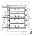
本発明に係る電気化学的エネルギー貯蔵装置は、複数の平型ガルバニセル3が設けられているハウジング2を備える。隣り合うそれぞれ2つの平型ガルバニセル3の間に、1つの平型熱伝導体4および/あるいは平型弾性体5が設けられている。
The electrochemical energy storage device according to the present invention includes a
たとえば図1に概略的に表わされているように、角柱のガルバニセル3の2つの大きな面に、好適にはそれぞれ1つの熱伝導体4と弾性体5とが設けられている。その際、セルと弾性体5との距離と容積が対応して寸法決めされれば、弾性体5は、セルの接触面と弾性体の接触面との間に作用する力11によって圧迫されることが達成され得る。この処置によって、関係する物体の接触面すなわち熱伝導体4とガルバニセル3と弾性体5の接触面に、面圧が生じることが達成され得、当該面圧は、ガルバニセル3が熱伝導体4の間で押込まれ、それによっていわば固定されるようにする。
For example, as schematically shown in FIG. 1, two large surfaces of a prismatic
ガルバニセル3のそれぞれ1つの表面が熱伝導体4と熱的に接触しているので、この熱伝導体4は、接触面に生じる熱を、熱伝導力によって誘導できる。熱伝導体4が付加的に、ハウジングの対応する構造体9に機械的に固定されており、その結果、接触面に対して垂直に熱伝導体が移動できなければ、それによってガルバニセル3も、接触面に対して垂直の方向での移動が阻止され、あるいは少なくとも困難になり、あるいは最小限に限定される。
Since each one surface of the
存在する面圧の圧力はさらに、ガルバニセル3がそれぞれ、隣接する熱伝導体4に圧迫され、それによってガルバニセル3と熱伝導体4との間の熱移行が改善されるようにする。ガルバニセル3を冷却する場合には、矢印10が、ガルバニセル3から熱伝導体4への熱流を明示している。矢印10は同時に、ガルバニセル3を熱伝導体4に圧迫する力を明示している。
The surface pressure pressure present further causes each
図1に表わされているように、平型ガルバニセル3、平型熱伝導体4および/あるいは平型弾性体5は、接触面で、面圧の意味での力を互いにかけ合う。好ましくはこれは、少なくとも1つの熱伝導体4が、当該熱伝導体が接触面に作用する力11の方向に移動できないように係合する、1つの構造体あるいは複数の構造体8,9を有する、少なくとも1つの壁をハウジングが備えることによって達成される。
As shown in FIG. 1, the flat
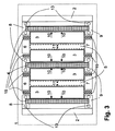
図2は本発明のさらなる好ましい実施形態を示しており、熱伝導体が、ハウジング2から突出する熱交換要素12と熱伝導可能に接合されている。そのような熱交換要素12は、好適には、冷却面あるいは冷却リブの形状で、あるいは類似のやり方で実施され得る。その際、これらの熱交換要素12が、熱伝導体4の熱移行面を熱移動媒体に対してできる限り拡大させ、それによってこのやり方で、熱伝導体4と周辺との間のできる限り効率的な熱移行を行えば、有利である。
FIG. 2 shows a further preferred embodiment of the invention, in which a heat conductor is joined in a heat-conducting manner with a
そのような熱交換要素12と熱伝導体4は、他方でガルバニセル3の冷却だけでなく、その加熱にも用いられ得る。ガルバニセル3がたとえばその駆動温度より下であれば、熱伝導体4を加熱し、熱伝導体4がこの熱を、共通の接触面を介してガルバニセル3に放出することによって、これらのガルバニセルを効果的に加熱することが可能である。この場合、熱流は、矢印10によって表わされる方向とは逆に流れる。
Such a
この場合でも、たとえば、ガルバニセルの目下の温度を超える温度の熱移動媒体が、これらの熱交換要素を環流すれば、熱交換要素12は有利な変形実施形態を表わすことができる。
Even in this case, the
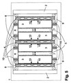
図3は本発明のさらなる好ましい実施形態を示しており、ハウジング要素8,9が、ガス状あるいは液体の熱移動媒体が貫流できる通路13を備える。本発明のこの実施形態では、ハウジング部品8,9と熱伝導体4との間の特に良好な熱伝導接触が特に有利である。なぜならば、このやり方で、ガルバニ要素3と、熱移動媒体が流れる通路13との間の熱流が、特に効果的に熱交換に寄与できるからである。
FIG. 3 shows a further preferred embodiment of the invention in which the
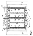
図4は本発明のさらなる実施形態を示しており、熱伝導体4自身が、ガス状あるいは液体の熱移動媒体が貫流できる通路14に貫通されている。本発明のこの実施形態では、ハウジング部品8,9は有利に、熱を絶縁するハウジング部品として実施されてよい。なぜならば、熱移動はこれらのハウジング部品を介して行われる必要がないからである。この実施形態のさらなる利点は、熱源あるいはヒートシンクすなわちガルバニセル3と熱移動媒体との間の熱移動経路が、ここに示された本発明の別の実施形態の場合よりも短いことにある。
FIG. 4 shows a further embodiment of the invention, in which the heat conductor 4 itself passes through a passage 14 through which a gaseous or liquid heat transfer medium can flow. In this embodiment of the invention, the
少なくとも、熱移動がハウジング部品8,9を介して行われる必要がないため、これらのハウジング部品が熱を絶縁するハウジング部品として実施され得る場合に、これらのハウジング部品8,9は、弾性体としても実施されてよい。これによって、電気化学的セル3の弾性のある収納のさらなる改善を達成することができる。
Since at least the heat transfer does not have to take place through the
図5と図6は、本発明のすでに記述された実施形態の組み合わせを示しており、ガルバニセル3と周辺との間の熱移動の有効性のさらなる増加を伴っている。
5 and 6 show a combination of the already described embodiments of the present invention, with a further increase in the effectiveness of heat transfer between the
図7においては、本発明のさらなる実施形態が概略的に明示されており、電気化学的(「ガルバニ」)セル3が、熱伝導体4に両側で接触され、それによってこれらのセルの冷却および/あるいは加熱の有効性をさらに上昇することができる。面圧は好適には、それぞれ1つのセル3と2つの熱伝導体4とから成るこれらのアセンブリの間に設けられた、圧迫された弾性体5によって、作り出され得る。
In FIG. 7, a further embodiment of the present invention is schematically illustrated, in which an electrochemical (“galvanic”)
示された構造上の処置は、本発明の実施例に応じて様々な利点を有する。これらの処置は様々なやり方で、車両に生じるできる限りすべての力を、ガルバニセル3からバッテリーハウジング2に伝達するという目的の達成に寄与する。このような力の伝達によって、ガルバニセル3の振動あるいはガルバニセル3とバッテリーハウジング2の相対運動が生じないことが保証され得る。
The structural treatment shown has various advantages depending on the embodiment of the invention. These treatments contribute in various ways to the achievement of the purpose of transmitting all possible forces generated in the vehicle from the
その際好適には複数のセル3が、熱伝導体4としての熱伝導板あるいは繊維複合プレートの間に設けられ、当該熱伝導板あるいは繊維複合プレートは、ハウジングの構造体8,9に固定されている場合に同時に固定プレートとして使われる熱伝導板とセル表面との間に前調節された面圧を有する。その際固定プレート4は、矢印10の方向で直交する慣性力を、電極パケットの表面から中間プロフィール8,9に、あるいは直接バッテリーハウジングに伝達する。その上固定プレートは熱伝導体4として、ガルバニセル3の表面から周囲たとえば冷却循環器への熱伝導に寄与する。
In this case, a plurality of
好適には固定プレートは、ガルバニセルと固定プレートとの間に遊びと相対運動なしに慣性力の伝達が行われるように、実施されている。その際考えられ得る実施形態は、固定プレートとバッテリーハウジングとの間あるいは固定プレートと中間プロフィール8,9との間のネジ接合である。
The fixing plate is preferably implemented in such a way that an inertial force is transmitted between the galvanic cell and the fixing plate without play and relative movement. A possible embodiment is then a screw connection between the fixing plate and the battery housing or between the fixing plate and the
別の可能性は、バッテリーハウジングあるいは中間プロフィールに溝を備え、この溝に固定プレートが噛み合うことである。これの代替として、固定プレートと中間プロフィールとは、好適には一体的な部材としても実施されてよく、バッテリーハウジングと螺合されてよい。この変形実施形態では、周回するフレームを有する固定プレートが使用されるであろう。これの代替として、固定プレートとバッテリーハウジングとは、好適には一体的な部材としても実施されてよい。本発明を実現するためのさらなる可能性は、底面プレート、固定プレートおよび/あるいは中間プロフィールを、バッテリーハウジングの側壁あるいは蓋部と接合して隆起と湾曲に対する高い剛性を有する支持構造体にすることである。 Another possibility is to have a groove in the battery housing or intermediate profile, and the fixing plate engages in this groove. As an alternative to this, the fixing plate and the intermediate profile may preferably be implemented as an integral member and may be screwed onto the battery housing. In this alternative embodiment, a fixed plate with a rotating frame would be used. As an alternative to this, the fixing plate and the battery housing may preferably also be implemented as an integral member. A further possibility for realizing the present invention is to join the bottom plate, the fixed plate and / or the intermediate profile to the side wall or lid of the battery housing into a support structure with high rigidity against bulge and curvature. is there.
本発明の対応する実施形態では、中間プロフィールは、水平と垂直の慣性力も、ガルバニセル3の端面からバッテリーハウジング2に伝達する。
In a corresponding embodiment of the invention, the intermediate profile also transmits horizontal and vertical inertia forces from the end face of the
たとえばリチウムイオン平型セルにおいてそうであり得るように、駆動時のガルバニセルの厚さが変化させられる限りにおいて、このような厚さの変化は、それぞれ2つのガルバニセルの間の弾性体5の変形によって補償され得る。
For example, as in a lithium ion flat cell, as long as the thickness of the galvanic cell during driving can be changed, such a change in thickness is caused by deformation of the
本発明のいくつかの実施例で備わっている通路は、電気的エネルギー貯蔵装置の冷却あるいは加熱の有効性を改善するための、熱移動媒体の貫流に用いられる。好ましくはその際、最大限許容し得るガルバニセルの駆動温度を維持することに用いられるべき液体冷却が使用される。ガルバニセルのそのような冷却は、走行中の車両においても停止中の車両においても、特に電気化学的エネルギー貯蔵装置の充電時にも、発生するセルの熱を確実に周囲にあるいは車両の暖房のために車両内部に排出することを保証する。 The passages provided in some embodiments of the present invention are used to flow through a heat transfer medium to improve the effectiveness of cooling or heating the electrical energy storage device. Preferably, liquid cooling is used here, which should be used to maintain the maximum allowable galvanic cell drive temperature. Such cooling of the galvanic cell ensures that the heat generated in the cell, both in the running vehicle and in the stopped vehicle, especially when charging the electrochemical energy storage device, to the surroundings or for heating the vehicle. Guarantee that it will be discharged into the vehicle.
そのような液体冷却は好適には、冷却剤循環器を使ってかつそれに接続されている熱交換器によって実現され得る。これの代替として、気化装置とコンデンサとコンプレッサとを有する冷却剤循環器あるいは冷媒循環器が実現され得る。2つの循環器の組み合わせが可能であり、かつ応用目的によっては有利でもあり得る。 Such liquid cooling can preferably be achieved by means of a heat exchanger using and connected to a coolant circulator. As an alternative to this, a coolant circulator or refrigerant circulator having a vaporizer, a condenser and a compressor can be realized. A combination of two circulators is possible and may be advantageous depending on the application purpose.
電気化学的エネルギー貯蔵装置は有利には、走行駆動、停止、充電駆動のサイクルにおいて、走行駆動中の車両の走行距離の最大化とエネルギー消費の最小化のために意図して使用され得る蓄熱装置としても用いられてよい。これを達成するために、電気化学的エネルギー貯蔵装置が充電時に優先的に冷却されれば、有利である。 The electrochemical energy storage device is advantageously a heat storage device that can be used with the intention of maximizing the mileage and minimizing energy consumption of the vehicle during travel drive in a travel drive, stop, charge drive cycle May also be used. In order to achieve this, it is advantageous if the electrochemical energy storage device is preferentially cooled during charging.
別の実施例とも組み合わせ可能な、本願発明のさらなる好ましい実施例に従えば、隣り合う貯蔵セルの間の中間室に、潜熱蓄熱装置が設けられている。これらの潜熱蓄熱装置は、弾性体と同一であってもあるいは弾性体に収納されていてもよい。しかし潜熱蓄熱装置は、熱伝導体に組み込まれていてもよい。好適には潜熱蓄熱装置は、セル間の中間室の全長と全幅にわたって延伸しており、好適には、その溶解熱がバッテリーの作動温度よりいくらか上にある物質を含む。そのような材料の溶解熱は、貯蔵セルの損失熱を受け入れることによって、電気化学的エネルギー貯蔵装置の冷却に用いられ得る。組み込まれた潜熱蓄熱装置に付加的に、あるいは代替的に、外部に取り付けられた蓄熱装置との熱交換も行われてよい。 According to a further preferred embodiment of the invention, which can be combined with another embodiment, a latent heat storage device is provided in the intermediate chamber between adjacent storage cells. These latent heat storage devices may be the same as the elastic body or may be accommodated in the elastic body. However, the latent heat storage device may be incorporated in the heat conductor. Preferably, the latent heat storage device extends over the entire length and width of the intermediate chamber between the cells, and preferably includes a material whose heat of fusion is somewhat above the operating temperature of the battery. The heat of dissolution of such materials can be used to cool the electrochemical energy storage device by accepting the heat loss of the storage cell. In addition to or in place of the built-in latent heat storage device, heat exchange with an external heat storage device may also be performed.
熱伝導体がガルバニセルの全長と全幅にわたって延伸する、本発明の実施形態の根本的な利点は、貯蔵セルから放出される熱が、貯蔵セルの全長と全幅とにわたって排出され得、それによって、貯蔵セルの表面と貯蔵セル内部での垂直温度勾配と水平温度勾配とが回避されるということにある。 The fundamental advantage of embodiments of the present invention where the heat conductor extends over the entire length and width of the galvanic cell is that the heat released from the storage cell can be exhausted over the entire length and width of the storage cell, thereby storing it. The vertical and horizontal temperature gradients inside the cell surface and inside the storage cell are avoided.
すべてのガルバニセルが熱交換器に対してほぼ同距離になるように熱交換器を設けることが、熱交換器使用の際に特に有利である。このやり方で、ガルバニセル間の均等な温度分布が少なくともほとんど保証されていることを達成できる。特に有利なのは、本発明に係る電気化学的エネルギー貯蔵装置に、組み込まれた冷却器と分離した熱交換器と組み込まれた潜熱蓄熱装置とから組み合わされたシステムを装備することである。必要な場合には、あらゆる場合に電気化学的エネルギー貯蔵装置のよどみ点温度の維持を保証するために、電気的に駆動される加熱要素を熱交換器に組み込んでもよい。 It is particularly advantageous when using a heat exchanger to provide a heat exchanger so that all galvanic cells are at approximately the same distance to the heat exchanger. In this way, it can be achieved that an even temperature distribution between the galvanic cells is at least almost guaranteed. It is particularly advantageous to equip the electrochemical energy storage device according to the invention with a system that combines an integrated cooler, a separate heat exchanger and an integrated latent heat storage device. If necessary, an electrically driven heating element may be incorporated into the heat exchanger to ensure maintenance of the stagnation temperature of the electrochemical energy storage device in all cases.
車両の乗客室を温度調節するために、好適には気化装置と、膨張弁と、コレクタあるいは乾燥機と、コンデンサと、好適には電気的に駆動されるコンプレッサとから成る冷媒循環器を備えることが有利である。 In order to regulate the temperature of the passenger compartment of the vehicle, it preferably comprises a refrigerant circulator consisting of a vaporizer, an expansion valve, a collector or dryer, a condenser, and preferably an electrically driven compressor. Is advantageous.
充電時あるいは放電時に電気化学的エネルギー貯蔵装置に生じる損失熱を受け入れるために、電気化学的エネルギー貯蔵装置の熱容量をできる限り良好に利用するために、放電プロセスの終わりに、電気化学的エネルギー貯蔵装置のまさに許容し得る最高温度が達成されるように、バッテリーの冷却を制御することが有利であり、ひいては好ましい。このやり方で、充電プロセスあるいは放電プロセスで生じる損失熱のできる限り大部分を、電気化学的エネルギー貯蔵装置の熱容量に貯蔵することが可能である。 In order to take advantage of the heat capacity of the electrochemical energy storage device as well as possible to accept the heat loss generated in the electrochemical energy storage device during charging or discharging, the electrochemical energy storage device at the end of the discharging process It is advantageous and thus preferred to control the cooling of the battery so that the very maximum allowable temperature is achieved. In this way, it is possible to store as much as possible of the heat lost during the charging or discharging process in the heat capacity of the electrochemical energy storage device.
これを達成するために、一般的に有利なのは、バッテリー加熱を制御するための温度設定値をできる限り低く、つまり好適には最小限許容し得る駆動温度よりいくらか高く調節することである。その際、熱エネルギーが電気化学的エネルギー貯蔵装置の冷却を介して排出される前に、電気化学的エネルギー貯蔵装置の熱容量がまず完全に利用されれば、電気化学的エネルギー貯蔵装置のエネルギーバランスに、しばしば特に好都合に作用する。 In order to achieve this, it is generally advantageous to adjust the temperature setpoint for controlling battery heating as low as possible, i.e. preferably somewhat above the minimum acceptable drive temperature. At that time, if the heat capacity of the electrochemical energy storage device is first fully utilized before the heat energy is discharged through the cooling of the electrochemical energy storage device, the energy balance of the electrochemical energy storage device can be improved. Often works particularly well.
図に基づく本願発明の記述に関連して、以下の参照符号が用いられた。 In connection with the description of the invention based on the figures, the following reference numerals have been used.
1 電気化学的エネルギー貯蔵装置
2 ハウジング
3 電気化学的(ガルバニ)セル
4 熱伝導体
5 弾性体
6、7、8、9 ハウジング部品、ハウジングの構造体
10 力もしくは熱流の方向を示す矢印
11 力の方向を示す矢印
12 熱交換要素
13 ハウジング構造体もしくは中間プロフィールの通路
14 熱伝導体の通路
15 導体、電気的接続接触部
DESCRIPTION OF
Claims (12)
隣り合う2つの平型ガルバニセルの間に、それぞれ1つの平型熱伝導体(4)および/あるいは平型弾性体(5)が設けられていることを特徴とする電気化学的エネルギー貯蔵装置。 In an electrochemical energy storage device (1) having a housing (2) provided with a plurality of flat galvanic cells (3),
An electrochemical energy storage device, wherein one flat heat conductor (4) and / or flat elastic body (5) is provided between two adjacent flat galvanic cells.
隣り合う2つの平型ガルバニセルの間に、それぞれ1つの平型熱伝導体(4)および/あるいは平型弾性体(5)が設けられることを特徴とする方法。 In a method for cooling or heating an electrochemical energy storage device having a housing (2) provided with a plurality of flat galvanic cells (3),
A method characterized in that one flat thermal conductor (4) and / or flat elastic body (5) is provided between two adjacent flat galvanic cells.
Applications Claiming Priority (3)
| Application Number | Priority Date | Filing Date | Title |
|---|---|---|---|
| DE102009040147A DE102009040147A1 (en) | 2009-09-04 | 2009-09-04 | Electrochemical energy storage device for vehicles and method for cooling or heating such an electrochemical energy storage device |
| DE102009040147.4 | 2009-09-04 | ||
| PCT/EP2010/005289 WO2011026592A1 (en) | 2009-09-04 | 2010-08-27 | Electrochemical energy store for vehicles and method for cooling or heating such an electrochemical energy store |
Publications (2)
| Publication Number | Publication Date |
|---|---|
| JP2013504147A true JP2013504147A (en) | 2013-02-04 |
| JP2013504147A5 JP2013504147A5 (en) | 2013-09-26 |
Family
ID=42938386
Family Applications (1)
| Application Number | Title | Priority Date | Filing Date |
|---|---|---|---|
| JP2012527222A Pending JP2013504147A (en) | 2009-09-04 | 2010-08-27 | Electrochemical energy storage device for vehicles and method for cooling or heating such electrochemical energy storage device |
Country Status (8)
| Country | Link |
|---|---|
| US (1) | US20120282506A1 (en) |
| EP (1) | EP2474055B1 (en) |
| JP (1) | JP2013504147A (en) |
| KR (1) | KR20120060879A (en) |
| CN (1) | CN102576824A (en) |
| BR (1) | BR112012004909A2 (en) |
| DE (1) | DE102009040147A1 (en) |
| WO (1) | WO2011026592A1 (en) |
Cited By (13)
| Publication number | Priority date | Publication date | Assignee | Title |
|---|---|---|---|---|
| JP2012204039A (en) * | 2011-03-24 | 2012-10-22 | Kayaba Ind Co Ltd | Electrical storage device |
| JP2014157721A (en) * | 2013-02-15 | 2014-08-28 | Honda Motor Co Ltd | Battery module and battery pack |
| JP2014170697A (en) * | 2013-03-05 | 2014-09-18 | Honda Motor Co Ltd | Battery pack |
| JP2015204267A (en) * | 2014-04-16 | 2015-11-16 | 三菱電機株式会社 | battery pack |
| JP2016152096A (en) * | 2015-02-17 | 2016-08-22 | 株式会社豊田自動織機 | Battery module |
| WO2016147861A1 (en) * | 2015-03-19 | 2016-09-22 | 株式会社オートネットワーク技術研究所 | Electrical storage pack |
| JP2018029000A (en) * | 2016-08-16 | 2018-02-22 | 株式会社オートネットワーク技術研究所 | Power storage module |
| JP2018506828A (en) * | 2015-03-16 | 2018-03-08 | エルジー・ケム・リミテッド | Battery compression blocker and battery module including the same |
| JP2019009022A (en) * | 2017-06-26 | 2019-01-17 | 株式会社東芝 | Battery device |
| JP2020080219A (en) * | 2018-11-12 | 2020-05-28 | トヨタ自動車株式会社 | Battery pack |
| JP2021015678A (en) * | 2019-07-10 | 2021-02-12 | 本田技研工業株式会社 | Power storage module |
| JP2021150166A (en) * | 2020-03-19 | 2021-09-27 | 信越ポリマー株式会社 | Heat dissipation structure and battery having the same |
| JP2021150018A (en) * | 2020-03-16 | 2021-09-27 | 信越ポリマー株式会社 | Heat dissipation structure and battery having the same |
Families Citing this family (42)
| Publication number | Priority date | Publication date | Assignee | Title |
|---|---|---|---|---|
| DE102009048250A1 (en) * | 2009-10-05 | 2011-04-07 | Li-Tec Battery Gmbh | battery assembly |
| US8936864B2 (en) | 2010-07-07 | 2015-01-20 | GM Global Technology Operations LLC | Batteries with phase change materials |
| DE102011076575A1 (en) | 2011-05-27 | 2012-11-29 | Bmw Ag | Energy storage module of several, in particular prismatic memory cells and method for producing an energy storage module and method for producing an end plate for an energy storage module |
| DE102011076580A1 (en) | 2011-05-27 | 2012-11-29 | Bayerische Motoren Werke Aktiengesellschaft | Energy storage module of several prismatic storage cells |
| DE102011076583A1 (en) | 2011-05-27 | 2012-11-29 | Bayerische Motoren Werke Aktiengesellschaft | Energy storage module of several particular prismatic memory cells and method for producing an energy storage module |
| DE102011081393B4 (en) * | 2011-08-23 | 2015-06-03 | Continental Automotive Gmbh | Energy storage device for a motor vehicle |
| DE102011084536B4 (en) * | 2011-10-14 | 2018-02-15 | Continental Automotive Gmbh | Cooling device for an electrical energy storage and energy storage device |
| JP5751127B2 (en) * | 2011-10-21 | 2015-07-22 | 株式会社豊田自動織機 | Battery module |
| DE102011118106A1 (en) * | 2011-11-10 | 2013-05-16 | Westinghouse Electric Germany Gmbh | Heat storage module for use in modular heat accumulator in e.g. iron and steel industry, has storage elements for effectuation and achievement of temperature stratification and thermally disconnected or insulated from each other |
| KR20130062551A (en) * | 2011-12-05 | 2013-06-13 | 에스케이이노베이션 주식회사 | The battery module equipped with a flexible member |
| CN103247765B (en) * | 2012-02-06 | 2015-07-29 | 有量科技股份有限公司 | Heat dissipation battery module |
| EP2637234B1 (en) * | 2012-03-07 | 2014-10-15 | MAGNA STEYR Battery Systems GmbH & Co OG | Battery structure for a motor vehicle |
| DE102012207162A1 (en) * | 2012-04-30 | 2013-10-31 | Robert Bosch Gmbh | Process for the production of Li-ion battery modules and a corresponding Li-ion battery module |
| DE102012011083A1 (en) | 2012-06-02 | 2013-12-05 | Audi Ag | Memory element comprising a plurality of lithium cells |
| DE102012112294A1 (en) * | 2012-12-14 | 2014-06-18 | Dr. Ing. H.C. F. Porsche Aktiengesellschaft | Electric energy storage |
| JP5978983B2 (en) * | 2012-12-21 | 2016-08-24 | 株式会社豊田自動織機 | Battery module |
| DE102013201102A1 (en) * | 2013-01-24 | 2014-08-07 | Robert Bosch Gmbh | Device for controlling the temperature of battery cells |
| US20140255747A1 (en) * | 2013-03-06 | 2014-09-11 | Amita Technologies Inc Ltd. | Heat dissipating battery module |
| US10020531B2 (en) | 2013-03-14 | 2018-07-10 | Enerdel, Inc. | Battery system with internal cooling passages |
| US9296310B2 (en) * | 2014-03-18 | 2016-03-29 | Ford Global Technologies, Llc | Traction battery thermal management system |
| KR101743697B1 (en) * | 2014-04-14 | 2017-06-20 | 주식회사 엘지화학 | Battery module having separated cooling path and venting path and battery pack including the same |
| DE102015214659A1 (en) * | 2015-07-31 | 2017-02-02 | Volkswagen Aktiengesellschaft | Traction battery with a battery case |
| EP3139107B1 (en) * | 2015-09-04 | 2019-08-28 | Lumenion GmbH | Thermal storage device and method for operating a thermal storage device |
| CN105552268B (en) * | 2016-01-30 | 2018-06-22 | 华南理工大学 | It is a kind of to fill gelled multiple exit batteries of electric automobile air cooling battery case |
| DE102016004526A1 (en) | 2016-04-14 | 2016-12-22 | Daimler Ag | Temperature control device for an electric battery |
| DE102016219284A1 (en) | 2016-10-05 | 2018-04-05 | Bayerische Motoren Werke Aktiengesellschaft | Electric energy storage with an emergency cooling device |
| DE102016219283A1 (en) * | 2016-10-05 | 2018-04-05 | Bayerische Motoren Werke Aktiengesellschaft | Electric energy storage with cooling plates arranged between the cells for emergency cooling |
| EP3316339B1 (en) * | 2016-10-26 | 2018-10-24 | Samsung SDI Co., Ltd. | A cooling system for cooling electrochemical cells of a battery system |
| KR102410517B1 (en) * | 2017-08-11 | 2022-06-20 | 현대자동차주식회사 | Battery module |
| KR102600089B1 (en) * | 2018-10-12 | 2023-11-07 | 주식회사 엘지에너지솔루션 | Battery module |
| DE102019109812B3 (en) | 2019-04-12 | 2020-06-10 | Airbus Defence and Space GmbH | Cooling element, device and method for cooling battery cells, in particular for pouch cells, and battery pack |
| KR102479967B1 (en) * | 2019-05-10 | 2022-12-20 | 주식회사 엘지에너지솔루션 | Battery module |
| DE102019207998A1 (en) * | 2019-05-31 | 2020-12-03 | Siemens Mobility GmbH | Energy storage device and vehicle |
| DE102019208806B3 (en) * | 2019-06-18 | 2020-08-27 | Audi Ag | Method for injecting a filling compound, in particular a heat-conducting paste, into a battery module device, injection system and motor vehicle with a battery module device |
| KR20210152238A (en) * | 2020-06-08 | 2021-12-15 | 주식회사 엘지에너지솔루션 | Battery Pack With Multi-Layered Battery Modules |
| DE102021115657A1 (en) | 2021-06-17 | 2022-12-22 | Dr. Ing. H.C. F. Porsche Aktiengesellschaft | Liquid-cooled automotive traction battery module |
| EP4123253B1 (en) * | 2021-07-20 | 2023-07-12 | Rosenberger Hochfrequenztechnik GmbH & Co. KG | Multi-layer latent heat storage |
| DE102021127920A1 (en) | 2021-10-27 | 2023-04-27 | Bayerische Motoren Werke Aktiengesellschaft | Electrical energy store for a motor vehicle, in particular for a motor vehicle, and motor vehicle |
| JP2023074273A (en) * | 2021-11-17 | 2023-05-29 | プライムプラネットエナジー&ソリューションズ株式会社 | battery module |
| FR3131093A1 (en) * | 2021-12-20 | 2023-06-23 | Renault S.A.S. | Battery module comprising a fluid applying pressure to a cell |
| DE102022110300A1 (en) | 2022-04-28 | 2023-11-02 | Bayerische Motoren Werke Aktiengesellschaft | Heat exchange element for a high-voltage storage module |
| CN114744348B (en) * | 2022-05-17 | 2023-11-14 | 江苏富士特电气技术有限公司 | Electrochemical energy storage device adapting to multiple types of electric appliances |
Citations (4)
| Publication number | Priority date | Publication date | Assignee | Title |
|---|---|---|---|---|
| JP2004071178A (en) * | 2002-08-01 | 2004-03-04 | Nissan Motor Co Ltd | Battery assembly |
| JP2004235110A (en) * | 2003-01-31 | 2004-08-19 | Yuasa Corp | Battery |
| JP2006252821A (en) * | 2005-03-08 | 2006-09-21 | Toyota Motor Corp | Battery module, battery pack, and manufacturing method of battery module |
| JP2009170687A (en) * | 2008-01-17 | 2009-07-30 | Meidensha Corp | Electrochemical power storage element module |
Family Cites Families (8)
| Publication number | Priority date | Publication date | Assignee | Title |
|---|---|---|---|---|
| US1881461A (en) * | 1929-03-05 | 1932-10-11 | John E Furtney | Battery carrier terminal assembly |
| DE4340007A1 (en) * | 1992-12-05 | 1994-06-09 | Volkswagen Ag | Car battery mount - has springs or rubber blocks, or has battery encased in thick rubber container with lid |
| DE19503085C2 (en) * | 1995-02-01 | 1997-02-20 | Deutsche Automobilgesellsch | Battery module with several electrochemical cells |
| KR20040082437A (en) * | 2002-02-19 | 2004-09-24 | 쓰리엠 이노베이티브 프로퍼티즈 컴파니 | Temperature control apparatus and method for high energy electrochemical cells |
| US7018701B2 (en) * | 2002-06-06 | 2006-03-28 | Fuji Polymer Industries Co., Ltd. | Thermally conductive sheet and method for manufacturing the same |
| JP4494719B2 (en) * | 2003-01-24 | 2010-06-30 | 古河電気工業株式会社 | Storage battery heat sink and storage battery cooling device |
| JP2009140714A (en) * | 2007-12-05 | 2009-06-25 | Furukawa Battery Co Ltd:The | Battery pack module |
| DE102007063191A1 (en) * | 2007-12-20 | 2009-06-25 | Daimler Ag | Battery, in particular for use in a vehicle |
-
2009
- 2009-09-04 DE DE102009040147A patent/DE102009040147A1/en not_active Withdrawn
-
2010
- 2010-08-27 JP JP2012527222A patent/JP2013504147A/en active Pending
- 2010-08-27 EP EP10749475.9A patent/EP2474055B1/en not_active Not-in-force
- 2010-08-27 WO PCT/EP2010/005289 patent/WO2011026592A1/en active Application Filing
- 2010-08-27 US US13/393,195 patent/US20120282506A1/en not_active Abandoned
- 2010-08-27 CN CN2010800391325A patent/CN102576824A/en active Pending
- 2010-08-27 KR KR1020127008657A patent/KR20120060879A/en not_active Application Discontinuation
- 2010-08-27 BR BR112012004909A patent/BR112012004909A2/en not_active IP Right Cessation
Patent Citations (4)
| Publication number | Priority date | Publication date | Assignee | Title |
|---|---|---|---|---|
| JP2004071178A (en) * | 2002-08-01 | 2004-03-04 | Nissan Motor Co Ltd | Battery assembly |
| JP2004235110A (en) * | 2003-01-31 | 2004-08-19 | Yuasa Corp | Battery |
| JP2006252821A (en) * | 2005-03-08 | 2006-09-21 | Toyota Motor Corp | Battery module, battery pack, and manufacturing method of battery module |
| JP2009170687A (en) * | 2008-01-17 | 2009-07-30 | Meidensha Corp | Electrochemical power storage element module |
Cited By (21)
| Publication number | Priority date | Publication date | Assignee | Title |
|---|---|---|---|---|
| JP2012204039A (en) * | 2011-03-24 | 2012-10-22 | Kayaba Ind Co Ltd | Electrical storage device |
| JP2014157721A (en) * | 2013-02-15 | 2014-08-28 | Honda Motor Co Ltd | Battery module and battery pack |
| JP2014170697A (en) * | 2013-03-05 | 2014-09-18 | Honda Motor Co Ltd | Battery pack |
| JP2015204267A (en) * | 2014-04-16 | 2015-11-16 | 三菱電機株式会社 | battery pack |
| JP2016152096A (en) * | 2015-02-17 | 2016-08-22 | 株式会社豊田自動織機 | Battery module |
| JP2018506828A (en) * | 2015-03-16 | 2018-03-08 | エルジー・ケム・リミテッド | Battery compression blocker and battery module including the same |
| WO2016147861A1 (en) * | 2015-03-19 | 2016-09-22 | 株式会社オートネットワーク技術研究所 | Electrical storage pack |
| JP2016177935A (en) * | 2015-03-19 | 2016-10-06 | 株式会社オートネットワーク技術研究所 | Power storage pack |
| US10333186B2 (en) | 2015-03-19 | 2019-06-25 | Autonetworks Technologies, Ltd. | Electricity storage pack |
| US10985414B2 (en) | 2016-08-16 | 2021-04-20 | Autonetworks Technologies, Ltd. | Power storage device including cooling member with bulging portion caused by evaporation of coolant |
| JP2018029000A (en) * | 2016-08-16 | 2018-02-22 | 株式会社オートネットワーク技術研究所 | Power storage module |
| WO2018034129A1 (en) * | 2016-08-16 | 2018-02-22 | 株式会社オートネットワーク技術研究所 | Power storage module |
| JP2019009022A (en) * | 2017-06-26 | 2019-01-17 | 株式会社東芝 | Battery device |
| JP2020080219A (en) * | 2018-11-12 | 2020-05-28 | トヨタ自動車株式会社 | Battery pack |
| JP7161673B2 (en) | 2018-11-12 | 2022-10-27 | トヨタ自動車株式会社 | assembled battery |
| JP2021015678A (en) * | 2019-07-10 | 2021-02-12 | 本田技研工業株式会社 | Power storage module |
| JP7094920B2 (en) | 2019-07-10 | 2022-07-04 | 本田技研工業株式会社 | Power storage module |
| JP2021150018A (en) * | 2020-03-16 | 2021-09-27 | 信越ポリマー株式会社 | Heat dissipation structure and battery having the same |
| JP7399760B2 (en) | 2020-03-16 | 2023-12-18 | 信越ポリマー株式会社 | Heat dissipation structure and battery equipped with the same |
| JP2021150166A (en) * | 2020-03-19 | 2021-09-27 | 信越ポリマー株式会社 | Heat dissipation structure and battery having the same |
| JP7399764B2 (en) | 2020-03-19 | 2023-12-18 | 信越ポリマー株式会社 | Heat dissipation structure and battery equipped with the same |
Also Published As
| Publication number | Publication date |
|---|---|
| EP2474055B1 (en) | 2014-04-09 |
| EP2474055A1 (en) | 2012-07-11 |
| BR112012004909A2 (en) | 2016-04-05 |
| CN102576824A (en) | 2012-07-11 |
| KR20120060879A (en) | 2012-06-12 |
| DE102009040147A1 (en) | 2011-03-10 |
| US20120282506A1 (en) | 2012-11-08 |
| WO2011026592A1 (en) | 2011-03-10 |
Similar Documents
| Publication | Publication Date | Title |
|---|---|---|
| JP2013504147A (en) | Electrochemical energy storage device for vehicles and method for cooling or heating such electrochemical energy storage device | |
| JP5938115B2 (en) | Battery module, battery temperature management system, and vehicle including the system | |
| JP5137480B2 (en) | Power supply for vehicle | |
| JP5142605B2 (en) | Power supply for vehicle | |
| JP5804323B2 (en) | Power storage element and power storage device | |
| JP5456371B2 (en) | Battery system for vehicle and vehicle equipped with this battery system | |
| CN102104122B (en) | Battery pack and the vehicle comprising this battery pack | |
| JP5334420B2 (en) | Battery system | |
| JP5899132B2 (en) | Power storage module | |
| WO2016129571A1 (en) | Battery device | |
| WO2012133707A1 (en) | Power source device and vehicle provided with power source device | |
| WO2013146561A1 (en) | Power supply device, and vehicle and power storage device equipped with same | |
| JP2014514691A (en) | Energy storage device, energy storage cell and heat conducting element having elastic means | |
| JP2012516007A (en) | Temperature controlled battery system II | |
| JP6020942B2 (en) | Power storage device | |
| KR20140016326A (en) | Energy storage device | |
| JP5585621B2 (en) | Power supply for vehicle | |
| KR101781923B1 (en) | Battery cooler for vehicle | |
| US20150255835A1 (en) | Connection apparatus and method for controlling the temperature of battery cells, and temperature-control apparatus, battery module, battery pack, battery and battery system | |
| KR20170022741A (en) | Battery module | |
| CN217182265U (en) | Battery and electric equipment | |
| WO2014010437A1 (en) | Power source device and vehicle provided with said power source device | |
| KR102136858B1 (en) | A Coolong/Heating Structure composed of cylindrical battery Cells | |
| WO2022104547A1 (en) | Battery, device using battery, and method and device for preparing battery | |
| JP2020035565A (en) | Battery pack |
Legal Events
| Date | Code | Title | Description |
|---|---|---|---|
| A521 | Request for written amendment filed |
Free format text: JAPANESE INTERMEDIATE CODE: A523 Effective date: 20130807 |
|
| A621 | Written request for application examination |
Free format text: JAPANESE INTERMEDIATE CODE: A621 Effective date: 20130807 |
|
| A977 | Report on retrieval |
Free format text: JAPANESE INTERMEDIATE CODE: A971007 Effective date: 20140825 |
|
| A131 | Notification of reasons for refusal |
Free format text: JAPANESE INTERMEDIATE CODE: A131 Effective date: 20140902 |
|
| RD04 | Notification of resignation of power of attorney |
Free format text: JAPANESE INTERMEDIATE CODE: A7424 Effective date: 20141217 |
|
| A02 | Decision of refusal |
Free format text: JAPANESE INTERMEDIATE CODE: A02 Effective date: 20150323 |