JP2013250071A - Full charge capacity detection device and storage battery system - Google Patents
Full charge capacity detection device and storage battery system Download PDFInfo
- Publication number
- JP2013250071A JP2013250071A JP2012122900A JP2012122900A JP2013250071A JP 2013250071 A JP2013250071 A JP 2013250071A JP 2012122900 A JP2012122900 A JP 2012122900A JP 2012122900 A JP2012122900 A JP 2012122900A JP 2013250071 A JP2013250071 A JP 2013250071A
- Authority
- JP
- Japan
- Prior art keywords
- capacity
- fcc
- value
- reliability
- full charge
- Prior art date
- Legal status (The legal status is an assumption and is not a legal conclusion. Google has not performed a legal analysis and makes no representation as to the accuracy of the status listed.)
- Pending
Links
Images


Classifications
-
- Y—GENERAL TAGGING OF NEW TECHNOLOGICAL DEVELOPMENTS; GENERAL TAGGING OF CROSS-SECTIONAL TECHNOLOGIES SPANNING OVER SEVERAL SECTIONS OF THE IPC; TECHNICAL SUBJECTS COVERED BY FORMER USPC CROSS-REFERENCE ART COLLECTIONS [XRACs] AND DIGESTS
- Y02—TECHNOLOGIES OR APPLICATIONS FOR MITIGATION OR ADAPTATION AGAINST CLIMATE CHANGE
- Y02E—REDUCTION OF GREENHOUSE GAS [GHG] EMISSIONS, RELATED TO ENERGY GENERATION, TRANSMISSION OR DISTRIBUTION
- Y02E60/00—Enabling technologies; Technologies with a potential or indirect contribution to GHG emissions mitigation
- Y02E60/10—Energy storage using batteries
Abstract
Description
本発明は、満充電容量検出装置及び蓄電池システムに関する。 The present invention relates to a full charge capacity detection device and a storage battery system.
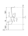
蓄電池から成る電池モジュールに流れる電流の積算量を、電池モジュールのSOC(state of charge)の変化量で除することにより、電池モジュールの満充電容量を検出する方法が知られている。この方法において、ΔSOC(SOCの変化量)が小さいとき、電池モジュールの電流測定値に含まれる誤差の影響が大きくなって、満充電容量の検出精度が低下する。例えば、図12に示す如く、停電時に備えて一定の残容量を確保しつつ平常時には所謂ピークシフト用の充放電を行うといった使用形態も存在するが、このような使用形態では、平常時の充放電におけるΔSOCが十分に大きくない可能性も高い。 There is known a method of detecting the full charge capacity of a battery module by dividing the integrated amount of current flowing through the battery module composed of a storage battery by the amount of change in the SOC (state of charge) of the battery module. In this method, when ΔSOC (the amount of change in SOC) is small, the influence of an error included in the current measurement value of the battery module increases, and the detection accuracy of the full charge capacity decreases. For example, as shown in FIG. 12, there is a usage form in which charge / discharge for so-called peak shift is performed in normal times while securing a certain remaining capacity in preparation for a power failure. There is a high possibility that ΔSOC in the discharge is not sufficiently large.
満充電容量の検出精度を向上させるべく、第1従来方法では、満充電容量の検出を行う際、通常使用状態のSOC下限値を超えて放電を行った後、SOC上限値を超えて充電を行うことで、ΔSOCを拡大させている(下記特許文献1参照)。第2従来方法では、ΔSOCが所定値より小さいとき、満充電容量の検出を実行しないようにしている(下記特許文献2参照)。
In order to improve the detection accuracy of the full charge capacity, in the first conventional method, when the full charge capacity is detected, the discharge exceeds the SOC lower limit value in the normal use state, and then the charge exceeds the SOC upper limit value. By doing so, ΔSOC is expanded (see
第1従来方法は、SOC下限値を超えた放電又はSOC上限値を超えた充電を許容できない使用形態(例えば、図12に示すような使用形態)に利用できないし、SOC下限値を超えた放電又はSOC上限値を超えた充電の実行期間中、電池モジュールの通常使用が制限される。また、第2従来方法では、ΔSOCが所定値よりも小さい状態が継続すると、満充電容量検出を継続的に実行できない。図12に示すような使用形態では、特に、ΔSOCが所定値を下回る状態が継続的に又は頻繁に発生しうる。 The first conventional method cannot be used for a usage pattern that cannot allow discharge exceeding the SOC lower limit value or charging exceeding the SOC upper limit value (for example, a usage pattern as shown in FIG. 12), and discharge exceeding the SOC lower limit value. Alternatively, normal use of the battery module is restricted during the charging period exceeding the SOC upper limit value. Further, in the second conventional method, when the state where ΔSOC is smaller than a predetermined value continues, the full charge capacity detection cannot be executed continuously. In the usage pattern as shown in FIG. 12, in particular, a state where ΔSOC falls below a predetermined value may occur continuously or frequently.
そこで本発明は、安定的に満充電容量を精度良く検出ならしめる満充電容量検出装置及び蓄電池システムを提供することを目的とする。 Therefore, an object of the present invention is to provide a full charge capacity detection device and a storage battery system that can detect a full charge capacity stably and accurately.
本発明に係る満充電容量検出装置は、蓄電池から成る電池モジュールの、対象期間中における残容量変化量と、前記対象期間中に前記電池モジュールに流れる電流の積算量とに基づき、前記電池モジュールの満充電容量を推定することで推定容量値を生成する満充電容量推定部と、前記残容量変化量に基づき前記推定容量値の信頼度を求める信頼度導出部と、複数のタイミングで生成された複数の推定容量値と、前記複数の推定容量値に対応する複数の信頼度とに基づき、前記満充電容量の出力容量値を生成する出力処理部と、を備えたことを特徴とする。 A full charge capacity detection device according to the present invention is based on a remaining capacity change amount of a battery module made of a storage battery during a target period and an integrated amount of current flowing through the battery module during the target period. A full charge capacity estimation unit that generates an estimated capacity value by estimating a full charge capacity, a reliability derivation unit that obtains a reliability of the estimated capacity value based on the remaining capacity change amount, and a plurality of timings And an output processing unit that generates an output capacity value of the full charge capacity based on a plurality of estimated capacity values and a plurality of reliability levels corresponding to the plurality of estimated capacity values.
本発明に係る蓄電池システムは、蓄電池から成る電池モジュールと、前記電池モジュールの満充電容量を検出する上記の満充電容量検出装置と、を備えたことを特徴とする。 A storage battery system according to the present invention includes a battery module including a storage battery, and the above-described full charge capacity detection device that detects a full charge capacity of the battery module.
本発明によれば、安定的に満充電容量を精度良く検出ならしめる満充電容量検出装置及び蓄電池システムを提供することが可能である。 ADVANTAGE OF THE INVENTION According to this invention, it is possible to provide the full charge capacity detection apparatus and storage battery system which can detect a full charge capacity stably accurately.
以下、本発明の実施形態の例を、図面を参照して具体的に説明する。参照される各図において、同一の部分には同一の符号を付し、同一の部分に関する重複する説明を原則として省略する。尚、本明細書では、記述の簡略化上、情報、信号、物理量、状態量又は部材等を参照する記号又は符号を記すことによって該記号又は符号に対応する情報、信号、物理量、状態量又は部材等の名称を省略又は略記することがある。 Hereinafter, an example of an embodiment of the present invention will be specifically described with reference to the drawings. In each of the drawings to be referred to, the same part is denoted by the same reference numeral, and redundant description regarding the same part is omitted in principle. In this specification, for simplification of description, a symbol or reference that refers to information, signal, physical quantity, state quantity, member, or the like is written to indicate information, signal, physical quantity, state quantity or Names of members and the like may be omitted or abbreviated.
<<第1実施形態>>
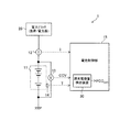
本発明の第1実施形態を説明する。図1は、本発明の第1実施形態に係る蓄電池システム1の概略全体構成図である。蓄電池システム1は、電池モジュール11、電流センサ12、電圧センサ13、温度センサ14及び電池制御部15を備える。電力ブロック20も蓄電池システム1の構成要素に含まれている、と考えても良い。
<< First Embodiment >>
A first embodiment of the present invention will be described. FIG. 1 is a schematic overall configuration diagram of a
電池モジュール11は、1以上の蓄電池(換言すれば二次電池)から成る。電池モジュール11を形成する蓄電池は、任意の種類の蓄電池であり、例えば、リチウムイオン電池、ニッケル水素電池である。図1では、直列接続された複数の蓄電池にて電池モジュール11が形成されているが、電池モジュール11を形成する蓄電池の個数は1でも良い。電池モジュール11に含まれる蓄電池の一部又は全部は、互いに並列接続されていても良い。以下では、電池モジュール11を1つの蓄電池として捉えて考える。本実施形態において、放電及び充電とは、特に記述なき限り電池モジュール11の放電及び充電を意味する。
The
電池モジュール11には電力ブロック20が接続されている。電力ブロック20は、負荷及び電力源から成る。電池モジュール11は、電力ブロック20内の負荷に対して放電電力を供給することができると共に電力ブロック20内の電力源から充電電力の供給を受けることができる。電池モジュール11と、電力ブロック20内の負荷及び電力源との間に、電力変換回路(不図示)が介在していても良い。
A
電流センサ12は、電池モジュール11と電力ブロック20との間に介在し、電池モジュール11に流れる電流の値(以下、電池電流値とも言う)を測定する。電流センサ12によって測定された電池電流値を記号Iにて表す。電圧センサ13は、電池モジュール11の出力電圧の値(以下、電池電圧値とも言う)を測定する。電圧センサ13によって測定された電池電圧値を記号CCVにて表す。電池電圧値CCVは、電池モジュール11の端子電圧値、電池モジュール11の正極及び負極間の電位差である。温度センサ14は、電池モジュール11の温度(以下、電池温度という)を測定する。温度センサ14によって測定された電池温度を記号Tにて表す。電池温度Tは、例えば、電池モジュール11内の蓄電池を包むパックの表面温度、又は、電池モジュール11内の特定部位における温度である。
The
センサ12、13及び14によって測定された電池電流値I、電池電圧値CCV及び電池温度Tは、電池制御部15に送られる。電池制御部15は、電池電流値I、電池電圧値CCV及び電池温度Tを含む電池状態データを用いて電池モジュール11の充電及び放電を制御する。
The battery current value I, the battery voltage value CCV, and the battery temperature T measured by the
電池制御部15は、満充電容量検出装置30を有している。満充電容量検出装置30は、電池電流値I、電池電圧値CCV及び電池温度Tに基づいて電池モジュール11の満充電容量を検出する。満充電容量検出装置30による満充電容量の検出値を記号FCCOUTにて表す。
The
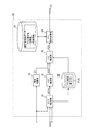
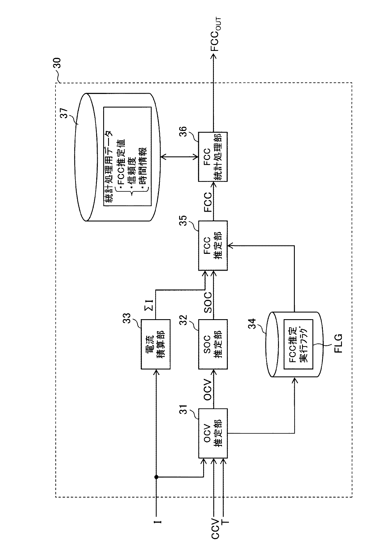
図2に、満充電容量検出装置30の内部ブロック図を示す。尚、以下では、センサ12、13及び14によって測定された電池電流値I、電池電圧値CCV及び電池温度Tを、測定電流値I、測定電圧値CCV及び測定温度Tと呼ぶこともあるし、測定値I、CCV及びTと呼ぶこともある。
FIG. 2 shows an internal block diagram of the full charge
満充電容量検出装置30は、測定値I、CCV及びTの全部又は一部を用いて電池モジュール11の開放電圧OCVを推定するOCV推定部31と、OCV推定部31による開放電圧OCVの推定値に基づき電池モジュール11の残容量指標であるSOC(state of charge)を推定するSOC推定部32と、測定値Iを積算することで電流積算量ΣIを算出する電流積算部33と、FCC推定部35によるFCC推定処理の実行/不実行を制御するためのFCC推定実行フラグFLGを保持及び記憶するフラグ記憶部34と、フラグFLGに“ON”が設定されている時にSOC推定部32の推定結果と電流積算部33の電流積算結果を用いて電池モジュール11の満充電容量FCCを推定するFCC推定部35と、統計処理用データを参照しつつFCC推定部35の推定結果を用いて満充電容量の検出値FCCOUTを算出及び出力するFCC統計処理部36と、統計処理用データを保持及び記憶する統計処理用データ記憶部37と、を備える。以下、図2に示される各部位の動作、機能及び構成を詳細に説明する。以下の説明における開放電圧、満充電容量、残容量及びSOCは、特に記述無き限り、電池モジュール11のそれらを指す。
The full charge
OCV推定部31は、電池モジュール11の充電及び放電が停止している時の測定電圧値CCVに基づき開放電圧OCVを推定し、開放電圧OCVを推定した際、FCC推定実行フラグFLGに“ON”を設定する。より具体的には例えば、充放電実行状態から充放電停止状態への切り替わり時点より所定の一定時間(例えば1時間)が経過した時点において、OCV推定部31は、測定電圧値CCVを電圧センサ13から取得し、取得した測定電圧値CCVを開放電圧OCVの値として推定及び導出すると共にフラグFLGに“ON”を設定する。OCV推定部31は、上記の一定時間を測定温度Tに応じて変化させても良い。充放電実行状態とは、電池モジュール11の充電又は放電が行われている状態を指し、例えば、測定電流値Iの絶対値が所定値ITHより大きい状態に相当する。充放電停止状態とは、電池モジュール11の充電及び放電が停止している状態を指し、例えば、測定電流値Iの絶対値が所定値ITH以下の状態に相当する。所定値ITHは、ゼロであっても良いし、微小な正の値であっても良い。OCV推定部31は、測定電流値Iに基づき、或いは、充放電実行状態及び充放電停止状態間を切り替えるスイッチング素子の状態に基づき、開放電圧OCVの推定タイミングを決定することができる。
The
電池モジュール11のSOCは、電池モジュール11の満充電容量に対する電池モジュール11の残容量の比であって、電池モジュール11の開放電圧OCVに依存する。SOC推定部32は、電池モジュール11の開放電圧OCVと残容量指標SOCとの関係を規定するテーブルデータ又は演算式を保持している。SOC推定部32は、そのテーブルデータ又は演算式を用いてOCV推定部31による開放電圧OCVの推定値を電池モジュール11の残容量指標SOCに変換する。
The SOC of the
電流積算部33は、任意の期間中における測定電流値Iを積算し、その積算値を電流積算量ΣIとして算出及び出力する。この積算が成される期間を、対象期間と呼ぶ。尚、電池モジュール11の放電時における電池電流値Iの極性が負であり、電池モジュール11の充電時における電池電流値Iの極性が正であるとする。
The current integrating
フラグ記憶部34は、半導体メモリ等にて形成され、フラグFLGを含む任意のフラグの状態を記憶及び保持する。フラグFLGには“ON”又は“OFF”が設定される。
The
FCC推定部35は、フラグFLGに“ON”が設定されているときに、電池モジュール11の満充電容量FCCを推定するFCC推定処理を実行する。フラグFLGに“ON”が設定されている場合、FCC統計処理部36により後続のFCC統計処理も実行される。フラグFLGに“OFF”が設定されている時には、FCC推定処理及びFCC統計処理は実行されない。OCV推定部31によってフラグFLGに“ON”が設定された後、1回分のFCC推定処理及びFCC統計処理が完了すると、OCV推定部31、FCC推定部35又はFCC統計処理部36によりフラグFLGに“OFF”が設定される。
The
図3を参照して、FCC推定処理を説明する。今、時刻ti-1及びti間において電池モジュール11の充電又は放電が行われたことを想定し、時刻ti-1及びtiにおいてSOC推定部32にて推定されたSOCを夫々SOCi-1及びSOCiにて表す。FCC推定処理は、フラグFLGに“ON”が設定される度に実行される。時刻ti-1は第(i−1)回目のFCC推定処理の実行タイミングに相当し、時刻tiは第i回目のFCC推定処理の実行タイミングに相当すると(iは整数)。電流積算部33は、FCC推定処理の実行タイミングに同期して積算処理を行うことができる。図3の例では、電流積算部33は、時刻ti-1及びti間の期間を対象期間に設定し、対象期間中の測定電流値Iを積算することで電流積算量ΣIを算出する。時刻ti-1及びti間の電流積算量ΣIを記号ΣIiにて表す。時刻ti-1及びti間におけるSOCの変化量をΔSOCiにて表す(下記式(A1)参照)。SOCは、電池モジュール11の残容量を比にて表したものであるため、ΔSOCiは残容量変化量の一種である。
The FCC estimation process will be described with reference to FIG. Now, the time t i-1 and t i between the assumption that the charging or discharging of the
FCC推定部35による満充電容量FCCの推定値を、便宜上、推定容量値とも呼ぶ。FCC推定部35は、下記式(A1)及び(A2)に従って、時刻tiにおける満充電容量FCCの推定値である推定容量値FCCiを算出する。推定容量値FCCiの算出後、電流積算部33は、電流積算量ΣIをリセットし、ΣI=0である状態を起点として時刻ti以降の測定電流値Iの積算を開始する。
ΔSOCi=SOCi−SOCi-1 ・・・(A1)
FCCi=ΣIi/ΔSOCi ・・・(A2)
The estimated value of the full charge capacity FCC by the
ΔSOC i = SOC i −SOC i−1 (A1)
FCC i = ΣI i / ΔSOC i (A2)
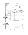
FCC統計処理部36は、複数の推定容量値を用いたFCC統計処理により、電池モジュール11の満充電容量の検出値である出力容量値FCCOUTを算出する。図4に、出力容量値FCCOUTの生成概念図を示す。図4において、波形311、312、313及び314は、夫々、測定電流値I、SOCの推定値、FCC推定値(推定容量値FCCi)及びFCC出力値(出力容量値FCCOUT)の波形を表している。波形313aは、波形314を示すグラフに波形313を点線にて重畳したものである。満充電容量検出装置30では、推定容量値FCCiをそのまま出力容量値FCCOUTとして出力するのではなく、各推定容量値FCCiの信頼度を考慮して出力容量値FCCOUTを決定する。
The FCC
電流センサ12による測定電流値Iには誤差(オフセット誤差及び非直線性誤差など)が含まれており、満充電容量FCCの推定に用いるΔSOCが小さいと、ΔSOCに対する測定電流値Iの誤差の比率が大きくなり、結果、推定容量値FCCiに対する測定電流値Iの誤差の影響が大きくなる。即ち、満充電容量FCCの推定に用いるΔSOCが小さいと、推定容量値FCCiに含まれる誤差が増大しがちになり、推定容量値FCCiの信頼度は低くなる。FCC統計処理では、比較的低い信頼度に対応する推定容量値が出力容量値FCCOUTにあまり反映されず、比較的高い信頼度に対応する推定容量値が出力容量値FCCOUTに大きく反映されるように、複数の推定容量値の統計値を出力容量値FCCOUTとして求める。図4では、例えば、ΔSOC2が小さいことに対応して推定容量値FCC2に対する信頼度が低く設定され、結果、時刻t2における推定容量値及び出力容量値間の差が特に大きくなっている。
The measured current value I by the
統計処理用データ記憶部37と合わせて、FCC統計処理の内容を詳細に説明する。図5は、FCC統計処理部36の内部ブロック図を含む、満充電容量検出装置30の一部ブロック図である。FCC統計処理部36は、信頼度導出部51、統計演算部52及び出力調整部53を備える。図6は、順次求められる残容量変化量ΔSOCi、推定容量値FCCi及び信頼度Wiと、各時刻との対応関係を示している。任意の整数iについて、時刻ti+1は時刻tiよりも遅く、時刻ti及びti+1において、電池モジュール11の放電若しくは充電、又は、充電及び放電の双方が行われたものとする。ΔSOCiは、時刻tiにて求められた残容量変化量(時刻ti-1及びti間におけるSOCの変化量)であり、FCCiは、時刻tiにて求められた推定容量値であり、Wiは、推定容量値FCCiに対応する信頼度である。
The details of the FCC statistical processing will be described in detail together with the statistical processing
統計処理用データ記憶部37は、半導体メモリ等にて形成され、推定容量値FCCi及び信頼度Wiが得られる度に、FCCi及びWiをそれらに対応する時間情報と共に統計処理用データに含めて記憶する。今、時刻tn-1以後であって且つ時刻tnの直前において、記憶部37は、推定容量値FCC1〜FCCn-1及び信頼度W1〜Wn-1を、それらに対応する時間情報と共に統計処理用データに含めて記憶しているとする。nは3以上の整数である。推定容量値FCCi及び信頼度Wiに対応する時間情報は、例えば時刻tiそのものであるが、時刻tiから現在時刻までの経過時間を求めることができる情報であれば任意である。任意の1つの時刻に対応する推定容量値、信頼度及び時間情報の組を、便宜上、組データと呼ぶ。
The statistical processing
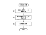
図7は、FCC統計処理の動作手順を表すフローチャートである。FCC統計処理は、ステップS11〜S13の処理から構成される。フラグFLGが“ON”となって推定容量値FCCiが得られる度に、ステップS11〜S13から成るFCC統計処理を行うことができる。ここでは、時刻tnが現在時刻であるとし、時刻tnにおけるFCC統計処理を説明する。 FIG. 7 is a flowchart showing the operation procedure of the FCC statistical processing. The FCC statistical process includes the processes of steps S11 to S13. Every time the flag FLG is “ON” and the estimated capacity value FCC i is obtained, the FCC statistical processing including steps S11 to S13 can be performed. Here, assuming that the time t n is the current time, the FCC statistical processing at the time t n will be described.
ステップS11において、FCC統計処理部36は、統計処理用データの更新処理を行う。統計処理用データの更新処理において、FCC統計処理部36は、記憶部37に記憶されている統計処理用データの内、上記経過時間が所定のデータ保持時間を超えた組データを統計処理用データの中から除外する。ここでは、図6に示す如く、所定のデータ保持時間が、時刻t2及びtn間の時間よりも長いが、時刻t1及びtn間の時間よりも短いものとする。そうすると、時刻tnに実行されるステップS11において、記憶部37に記憶されている統計処理用データの中から、FCC1、W1及びt1から成る組データが除外される(記憶部37の記憶内容から削除される)。
In step S <b> 11, the FCC
ステップS11の統計処理用データの更新処理において、信頼度導出部51は、新たな推定容量値に対応する新たな信頼度を導出する。ここでは、時刻tnにおいて推定容量値FCCnが新たに得られたことを想定しているため、新たな推定容量値FCCnに対応する新たな信頼度Wnが導出される。統計処理用データの更新処理では、FCCn、Wn及びtnから成る組データが統計処理用データに追加されて記憶部37に記憶される。結果、時刻tnにおける統計処理用データの更新処理の完了後、記憶部37内の統計処理用データには、FCC2〜FCCn、W2〜Wn及びt2〜tnが含まれていることになる。信頼度導出部51は、残容量変化量ΔSOCiの増大に伴って信頼度Wiが増大するように信頼度Wiを求める。具体的には例えば、下記式(A3)に従って信頼度Wiを求める。
Wi=ΔSOCi ・・・(A3)
In the statistical data update process in step S11, the
W i = ΔSOC i (A3)
ステップS11に続くステップS12において、統計処理部52は、記憶部37に記憶されている統計処理用データから統計容量値FCCAVEを算出する。この際、統計処理部52は、統計処理用データに含まれる推定容量値FCC2〜FCCnの内、比較的大きな信頼度に対応する推定容量値が、比較的小さな信頼度に対応する推定容量値よりも、統計容量値FCCAVEに大きく寄与するように(結果、出力容量値FCCOUTにも大きく寄与するように)、統計容量値FCCAVEを求める。具体的には例えば、統計処理部52は、信頼度W2〜Wnを加重平均係数として用いた、推定容量値FCC2〜FCCnの加重平均演算によって時刻tnの統計容量値FCCAVEを算出する。即ち、統計処理部52は、下記式(A4)に従って、時刻tnの統計容量値FCCAVEを算出することができる。
In step S12 following step S11, the
ステップS12に続くステップS13において、出力調整部53は、出力調整処理を介して統計容量値FCCAVEから出力容量値FCCOUTを決定する。出力調整処理において、出力調整部53は、複数の信頼度に応じて出力容量値FCCOUTの更新の有無を制御することができる。つまり例えば、出力調整処理において、出力調整部53は、原則として統計容量値FCCAVEをそのまま出力容量値FCCOUTとして出力するが、統計処理用データに含まれる信頼度の総和又は平均値(今の例において、W2〜Wnの和又は平均値)が所定の閾値よりも小さい場合においては、出力容量値FCCOUTを更新しない。信頼度の総和又は平均値が低い場合、統計容量値FCCAVEの、満充電容量の推定値としての信頼性が低いため、出力容量値FCCOUTを更新しない方が妥当な容量値を出力できるからである。より具体的には、出力調整部53は、統計処理用データに含まれる信頼度の総和又は平均値が所定の閾値以上である場合、FCCAVE[n−1]と一致していた出力容量値FCCOUTを時刻tnにおいてFCCAVE[n]に更新するが、その総和又は平均値が上記閾値よりも小さい場合、出力容量値FCCOUTを時刻tnにおいてFCCAVE[n]に更新せずにFCCAVE[n−1]のまま維持する。FCCAVE[i]は、時刻tiにおけるステップS12で求められる統計容量値FCCAVEを表す。
In step S13 following step S12, the
蓄電池システム1では、例えば、停電時に備えて一定の残容量を確保しつつ平常時には所謂ピークシフト用の充放電を行うといった使用形態が想定される(図12参照)。このような使用形態では、平常時の充放電におけるΔSOCが十分に大きくない可能性も高い。本実施形態では、このような使用形態においても、ΔSOCからFCC推定の信頼度を求めて信頼度に応じた統計処理を行うことで、妥当なFCC又は信頼性の高いFCCを検出及び出力することが可能となる。第2従来方法と異なり、ΔSOCが小さくても信頼度を考慮して安定的にFCCOUTを得ることができる(満充電容量検出が継続的に停止するといったことが回避される)。
In the
<<第2実施形態>>
本発明の第2実施形態を説明する。第2実施形態及び後述の第3〜第7実施形態では、第1実施形態で述べた技術の変形技術を説明する。第2〜第7実施形態の記載事項を第1実施形態に適用することができ、矛盾なき限り、第2〜第7実施形態の内の任意の2以上の実施形態の記載事項を自由に組み合わせて第1実施形態に適用することもできる。
<< Second Embodiment >>
A second embodiment of the present invention will be described. In the second embodiment and third to seventh embodiments described later, modified techniques of the technique described in the first embodiment will be described. The items described in the second to seventh embodiments can be applied to the first embodiment, and as long as there is no contradiction, the items described in any two or more of the second to seventh embodiments can be freely combined. It can also be applied to the first embodiment.
OCV推定部31は、第1実施形態で述べた方法以外の、公知の任意の開放電圧推定方法を用いて開放電圧OCVを推定しても良い。
The
或いは、OCV推定部31は、以下に示す方法を用いて開放電圧OCVを推定しても良い。図8(a)〜(c)及び図9を参照する。図8(a)は、電池モジュール11内の等価回路である。電池モジュール11内の等価回路は、電圧OCVを出力し且つ内部抵抗がゼロの電圧源VSと、抵抗成分と容量成分を含むインピーダンス回路Zとの直列接続回路である、と考えることができる。図8(b)及び図8(c)の回路ZA及びZBは、インピーダンス回路Zの内部回路の第1例及び第2例である。回路ZAは、抵抗R0と、抵抗R1及びコンデンサC1の並列接続回路とを直列接続した回路である。回路ZBは、抵抗R0と、抵抗R1及びコンデンサC1の並列接続回路と、抵抗R2及びコンデンサC2の並列接続回路と、を直列接続した回路である。以下では、特に記述なき限り、回路ZBをインピーダンス回路Zとみなす。
Or the
図9には、測定電圧値CCVの波形410CCVと、電池モジュール11の真の開放電圧値の波形410OCVとが示されている。図9では、時刻tA及びtB間の期間P0において充電及び放電が停止しており、その後、時刻tB及びtC間の期間P1において放電が行われ、その後、時刻tC及びtD間の期間P2において充電及び放電が停止している。時刻tC0は、時刻tC直前の時刻であって期間P1に属し、時刻tC1は、時刻tCより後の時刻であって期間P2に属する。OCV推定部31は、まず、時刻tC0の測定値CCV及びIであるCCVON[tC0]及びI[tC0]と、既知の抵抗値RTOTALに基づき、式(B1)に従って、時刻tC0の開放電圧OCVON:EST[tc0]を推定する。抵抗値RTOTALは、下記式(B2)に従う(数式においてR0、R1及びR2は、抵抗R0、R1及びR2の抵抗値を示す)。その後、時刻tC1において、OCV推定部31は、時刻tC1の測定値CCVであるCCVOFF[tC1]を用い、下記式(B3)に従って初期残存電圧VDIFFを求める。初期残存電圧VDIFFは、時刻tC1において回路Zに加わる電圧(回路Zに残存している電圧)である。
FIG. 9 shows a waveform 410 CCV of the measured voltage value CCV and a waveform 410 OCV of the true open-circuit voltage value of the
残存電圧VDIFFを求めた後、OCV推定部31は、下記式(B4)に従い、期間P2中の任意の時刻tにおける開放電圧OCVOFF:EST[t]を推定することができる。CCVOFF[t]は、期間P2中の時刻tにおける測定電圧値CCVである。VTRANS[t]は、期間P2中の時刻tにおいて回路Zに加わる電圧であり、回路ZBを回路Zとみなした場合、式(B5)に従って求められる。但し、式(B5)の右辺における“t”は時刻tC1からの経過時間を示す。VDIIF1及びVDIIF2は、初期残存電圧VDIFFと既知の係数α1及びα2を用いて、下記式(B6)〜(B9)に従い定められる。時定数τ1及びτ2は、実験等を介して予め設定される。RTOTAL、α1、α2、τ1及びτ2の値は、固定値でも良いが、測定温度T又は電池モジュール11の劣化度などに応じた可変値であっても良い。
After obtaining the residual voltage V DIFF , the
期間P1において充電が行われていた場合も同様の方法にて開放電圧の推定が可能である。本方法を用いれば、充電又は放電の停止後、電池モジュール11の端子電圧の安定を待たずとも、精度よく開放電圧を推定することが可能となる。OCV推定部31は、充電又は放電の停止後、開放電圧を精度良く推定できる条件が成立したときに(例えば、時刻tCから所定時間が経過したときに)、開放電圧OCVOFF:EST[t]の推定を行ってフラグFLGに“ON”を設定すればよい。
Even when charging is performed in the period P1, the open circuit voltage can be estimated by the same method. If this method is used, it is possible to accurately estimate the open-circuit voltage without waiting for the terminal voltage of the
<<第3実施形態>>
本発明の第3実施形態を説明する。信頼度Wiを用いたFCC統計処理によって出力容量値FCCOUTの信頼性が担保されるわけであるが、ΔSOCiが所定の下限値よりも小さい場合には、ΔSOCiを用いて推定容量値FCCiを求める処理、及び、FCCiを用いて行われるべきであったFCC統計処理を実行しないようにしても良い。
<< Third Embodiment >>
A third embodiment of the present invention will be described. Although the reliability of the output capacity value FCC OUT is ensured by the FCC statistical processing using the reliability W i , if ΔSOC i is smaller than a predetermined lower limit value, the estimated capacity value is calculated using ΔSOC i. The processing for obtaining FCC i and the FCC statistical processing that should have been performed using FCC i may not be executed.
<<第4実施形態>>
本発明の第4実施形態を説明する。信頼度Wiの導出式は上記の式(A3)に限定されない。例えば、信頼度導出部51は、式(A3a)、式(A3b)又は式(A3c)に従って、信頼度Wiを導出しても良い。
Wi=(ΔSOCi)2 ・・・(A3a)
Wi=ΔSOCi×(di-1+di) ・・・(A3b)
Wi=(ΔSOCi)2×(di-1+di) ・・・(A3c)
<< Fourth Embodiment >>
A fourth embodiment of the present invention will be described. The derivation formula of the reliability W i is not limited to the above formula (A3). For example, the
W i = (ΔSOC i ) 2 (A3a)
W i = ΔSOC i × (d i-1 + d i ) (A3b)
W i = (ΔSOC i ) 2 × (d i-1 + d i ) (A3c)
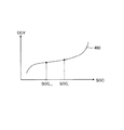
di-1及びdiの説明に図10を参照する。図10の曲線440は、SOC及びOCVを横軸及び縦軸にとった、OCV及びSOC間の関係を示す曲線である。図10には、SOC推定部32による時刻ti-1及びtiのSOCの推定値SOCi-1及びSOCiも示されている。SOCi-1及びSOCiは、信頼度Wiに対応するFCCiの推定に用いるΔSOCiの算出元の残容量指標である(上記式(A1)参照)。式(A3b)及び(A3c)において、diは、SOC=SOCi-1であるときの曲線440の傾きであり、di-1は、SOC=SOCiであるときの曲線440の傾きである。信頼度導出部51は、曲線440を特定可能なテーブルデータ等を保持し、そのテーブルデータ等を用いて、SOCi-1及びSOCiから傾きdi-1及びdiを得ることができる。傾きdi-1及びdiが大きい方が、SOC推定の精度が高く、結果、FCC推定の信頼度も高くなる。故に、式(A3b)及び(A3c)では、傾きdi-1及びdiの増加に伴って信頼度Wiを増加させている。
Refer to FIG. 10 for an explanation of d i−1 and d i . A curve 440 in FIG. 10 is a curve showing a relationship between the OCV and the SOC with the SOC and OCV taken on the horizontal axis and the vertical axis. FIG. 10 also shows SOC estimated values SOC i−1 and SOC i at times t i−1 and t i by the
また、FCC統計処理部36は、時刻tiで信頼度Wiを求めた後、時刻tiから時間が経過するにつれて信頼度Wiの値を減少させても良い。例えば、FCC統計処理部36は、時刻tiにて求めた信頼度Wiを初期信頼度Wi[INIT]として取扱い、時刻tiにてFCC統計処理を行う場合には、初期信頼度Wi[INIT]を信頼度Wiとして用いて時刻tiの統計容量値FCCAVEを算出する。その後、時刻ti+jにてFCC統計処理を行う場合には、信頼度補正量を初期信頼度Wi[INIT]から減じて得た信頼度を信頼度Wiとして用いて時刻ti+jの統計容量値FCCAVEを算出する(但し、jは正の整数であって、信頼度Wiの下限はゼロである)。信頼度補正量は、時刻ti及びti+j間の時間差の増大に伴って増大する。
Moreover, FCC
<<第5実施形態>>
本発明の第5実施形態を説明する。上記式(A4)による統計容量値FCCAVEの導出方法は例示に過ぎず、比較的大きな信頼度に対応する推定容量値が比較的小さな信頼度に対応する推定容量値よりも統計容量値FCCAVEに大きく寄与する限り、統計容量値FCCAVEの導出方法は様々に変形可能である。或いは、統計演算部52は、信頼度を用いずに複数の推定容量値FCCiから統計容量値FCCAVEを求めても良い。即ち例えば、統計演算部52は、下記式(A4a)に従い、複数の推定容量値FCCiの単純平均によって、時刻tnの統計容量値FCCAVEを算出しても良い。
<< Fifth Embodiment >>
A fifth embodiment of the present invention will be described. The method of deriving the statistical capacitance FCC AVE by the formula (A4) are merely exemplary, relatively large corresponding to the reliability is estimated capacitance value is relatively small reliability than the estimated capacitance value corresponding to the statistical capacity value FCC AVE As long as it greatly contributes to the above, the method for deriving the statistical capacity value FCC AVE can be variously modified. Alternatively, the
<<第6実施形態>>
本発明の第6実施形態を説明する。満充電容量は、基本的に、電池モジュール11の使用による劣化と共に減少してゆくはずである。故に、出力調整部53は、任意の時刻tiにて出力される出力容量値FCCOUTが初期の出力容量値FCCOUT(1番最初に求められた出力容量値FCCOUT)を超えないように、出力容量値FCCOUTに上限を課しても良い。即ち例えば、時刻tiにて求められた統計容量値FCCAVEが初期の出力容量値FCCOUTよりも大きいとき、出力調整部53は、その初期の出力容量値FCCOUTを、時刻tiの出力容量値FCCOUTとして出力しても良い。
<< Sixth Embodiment >>
A sixth embodiment of the present invention will be described. The full charge capacity should basically decrease with deterioration due to use of the
<<第7実施形態>>
本発明の第7実施形態を説明する。ステップS13の出力調整処理(図7参照)において、出力調整部53は、複数の信頼度Wiに応じた更新制限範囲を設定し、更新制限範囲内において出力容量値FCCOUTの更新を行うようにしても良い。
<< Seventh Embodiment >>
A seventh embodiment of the present invention will be described. In the output adjustment process (see FIG. 7) in step S13, the
図11を参照し、これを実現する方法例を説明する。図11において、各黒四角形は、各時刻において導出された各統計容量値FCCAVEを表しており、各範囲530は、各時刻において設定された各更新制限範囲を表している。統計容量値FCCAVEは、第1又は第5実施形態に記載の方法に従って求められる。実線折れ線510は、更新制限範囲の設定を含む出力調整処理を行った場合における、出力容量値FCCOUTの時間変化を表している。更新制限範囲の設定を含む出力調整処理を行った場合、各時刻の出力容量値FCCOUTは各時刻の更新制限範囲530内に収められる。参考用の破線折れ線520は、更新制限範囲の設定を含む出力調整処理を行わなかった場合(即ち、各時刻において導出された統計容量値FCCAVEをそのまま出力容量値FCCOUTとして出力する場合)における、出力容量値FCCOUTの時間変化を表している。
An example of a method for realizing this will be described with reference to FIG. In FIG. 11, each black square represents each statistical capacity value FCC AVE derived at each time, and each
ここでは、説明の具体化のため、第1実施形態と同様、時刻tnが現在時刻であるとし、時刻tnにおける更新制限範囲の設定を含む出力調整処理の説明を行う。時刻tnにおける出力調整処理において、出力調整部53は、まず、統計処理用データに含まれる信頼度の総和ΣWi(今の例において、W2〜Wnの和)又は平均値に基づき、エラー幅W_ERRを設定する。時刻tnにおける出力調整処理を行う際、第1実施形態で述べたように、統計処理用データに含まれる信頼度は信頼度W2〜Wnであるため、総和ΣWiは信頼度W2〜Wnの合計値である。例えば、出力調整部53は、下記式(C1)に従ってエラー幅W_ERRを設定する。kは所定の係数である。kは、総和ΣWiの元になる信頼度の個数、即ち(n−1)に比例する係数であっても良く、この場合、エラー幅W_ERRは信頼度W2〜Wnの平均値(ΣWi/(n−1))に反比例する。エラー幅W_ERRが、信頼度の総和又は平均値の増大に伴って減少する限り、エラー幅W_ERRの算出式は式(C1)に限定されない。
For the sake of concrete description, as in the first embodiment, the time t n is the current time, a description of the output adjustment processing including setting the update limit range at time t n. In the output adjustment process at the time t n , the
出力調整部53は、時刻tnにおける統計容量値FCCAVEを基準とし且つエラー幅W_ERRを持つ更新制限範囲を設定し、出力容量値FCCOUTの変動がなるだけ抑制されるように(即ち、出力容量値FCCOUTの変動が最小化されるように)更新制限範囲内において出力容量値FCCOUTの更新を行う。
The
説明の具体化及び明確化のため、時刻tn-1及びtnおける出力容量値FCCOUTを記号FCCOUT[n−1]及びFCCOUT[n]で表し、時刻tnおける統計容量値FCCAVEを記号FCCAVE[n]で表し、信頼度W2〜Wnに基づくエラー幅W_ERRを記号W_ERR[n]で表す。そうすると、以下の第1〜第3ケースへの場合分けを介して、FCCOUT[n]が決定される。第1〜第3ケースは、夫々、時刻tnが図11の時刻tX1〜tX3に相当する場合に対応している。つまり、出力調整部53は、
第1不等式“FCCOUT[n−1]≦FCCAVE[n]−W_ERR[n]”が成立する第1ケースにおいては、式“FCCOUT[n]=FCCAVE[n]−W_ERR[n]”にてFCCOUT[n]を求め、
第2不等式“FCCAVE[n]−W_ERR[n]<FCCOUT[n−1]<FCCAVE[n]+W_ERR[n]”が成立する第2ケースにおいては、式“FCCOUT[n]=FCCOUT[n−1]”にてFCCOUT[n]を求め(即ちFCCOUTを更新せず)、
第3不等式“FCCAVE[n]+W_ERR[n]≦FCCOUT[n−1]”が成立する第3ケースにおいては、式“FCCOUT[n]=FCCAVE[n]+W_ERR[n]”にてFCCOUT[n]を求める。
In order to clarify and clarify the description, the output capacity value FCC OUT at times t n−1 and t n is represented by symbols FCC OUT [n−1] and FCC OUT [n], and the statistical capacity value FCC at time t n is shown . AVE is represented by the symbol FCC AVE [n], and the error width W_ERR based on the reliability W 2 to W n is represented by the symbol W_ERR [n]. Then, FCC OUT [n] is determined through the case division into the following first to third cases. The first to third cases correspond to cases where the time t n corresponds to the times t X1 to t X3 in FIG. That is, the
In the first case where the first inequality “FCC OUT [n−1] ≦ FCC AVE [n] −W_ERR [n]” is satisfied, the expression “FCC OUT [n] = FCC AVE [n] −W_ERR [n]”. To find FCC OUT [n]
In the second case where the second inequality “FCC AVE [n] −W_ERR [n] <FCC OUT [n−1] <FCC AVE [n] + W_ERR [n]” is satisfied, the expression “FCC OUT [n] = FCC OUT [n-1] ”is used to obtain FCC OUT [n] (ie, FCC OUT is not updated)
In the third case where the third inequality “FCC AVE [n] + W_ERR [n] ≦ FCC OUT [n−1]” is satisfied, the expression “FCC OUT [n] = FCC AVE [n] + W_ERR [n]” is satisfied. To obtain FCC OUT [n].
信頼度の総和又は平均値が大きいとき、統計容量値FCCAVEの信頼性は高いため、統計容量値FCCAVEそのもの又はそれに近い値を出力容量値FCCOUTとして出力することに問題は少なく、また出力精度の面においても妥当である。故に、上記方法例では、信頼度の総和又は平均値が大きいときにエラー幅W_ERRを小さくしている。これに対し、信頼度の総和又は平均値が小さく統計容量値FCCAVEの信頼性が低い場合には、真の満充電容量から見た統計容量値FCCAVEの誤差が大きい可能性が高い。他方、ユーザ又は上位システムに提供される出力容量値FCCOUTが大きく変動することは妥当でない又は不自然であることも多い。従って、信頼度の総和又は平均値が小さく統計容量値FCCAVEの信頼性が低い場合には、更新制限範囲の幅に相当するエラー幅W_ERRを増大させて出力容量値FCCOUTの変動の抑制を優先する。このような方法により、FCC推定の信頼度に応じ、FCC出力値の精度担保及び変動抑制を両立できる。 Since the statistical capacity value FCC AVE has high reliability when the total or average value of reliability is large, there is little problem in outputting the statistical capacity value FCC AVE itself or a value close thereto as the output capacity value FCC OUT. It is reasonable in terms of accuracy. Therefore, in the above method example, the error width W_ERR is reduced when the reliability sum or average value is large. On the other hand, when the total or average value of the reliability is small and the reliability of the statistical capacity value FCC AVE is low, there is a high possibility that the error of the statistical capacity value FCC AVE viewed from the true full charge capacity is large. On the other hand, it is often inappropriate or unnatural that the output capacity value FCC OUT provided to the user or the host system fluctuates greatly. Therefore, when the total or average value of the reliability is small and the reliability of the statistical capacity value FCC AVE is low, the error width W_ERR corresponding to the width of the update limit range is increased to suppress the fluctuation of the output capacity value FCC OUT. Prioritize. By such a method, both accuracy guarantee and fluctuation suppression of the FCC output value can be achieved in accordance with the reliability of FCC estimation.
尚、第1又は第3ケースにおいても、信頼度の総和又は平均値が所定の閾値よりも小さい場合においては、第1実施形態で述べたように、出力容量値FCCOUTを更新しないようにしても良い(即ち、FCCOUT[n]=FCCOUT[n−1]、としても良い)。また、エラー幅W_ERRを信頼度の総和又は平均値に依存しない固定幅にすることも可能である。 Even in the first or third case, when the reliability sum or average value is smaller than the predetermined threshold, the output capacitance value FCC OUT is not updated as described in the first embodiment. (That is, FCC OUT [n] = FCC OUT [n−1] may be used). Further, the error width W_ERR may be a fixed width that does not depend on the sum of reliability or the average value.
<<変形等>>
本発明の実施形態は、特許請求の範囲に示された技術的思想の範囲内において、適宜、種々の変更が可能である。以上の実施形態は、あくまでも、本発明の実施形態の例であって、本発明ないし各構成要件の用語の意義は、以上の実施形態に記載されたものに制限されるものではない。上述の説明文中に示した具体的な数値は、単なる例示であって、当然の如く、それらを様々な数値に変更することができる。上述の実施形態に適用可能な注釈事項として、以下に、注釈1及び注釈2を記す。各注釈に記載した内容は、矛盾なき限り、任意に組み合わせることが可能である。
<< Deformation, etc. >>
The embodiment of the present invention can be appropriately modified in various ways within the scope of the technical idea shown in the claims. The above embodiment is merely an example of the embodiment of the present invention, and the meaning of the term of the present invention or each constituent element is not limited to that described in the above embodiment. The specific numerical values shown in the above description are merely examples, and as a matter of course, they can be changed to various numerical values. As annotations applicable to the above-described embodiment,
[注釈1]
満充電容量検出装置30を、ハードウェア、或いは、ハードウェアとソフトウェアの組み合わせによって構成することができる。装置30にて実現される機能の内、任意の特定の機能をプログラムとして記述して、該プログラムを装置30に搭載可能なフラッシュメモリに保存しておき、該プログラムを装置30内の演算処理装置(例えば、装置30又は電池制御部15に搭載可能なマイクロコンピュータ)上で実行することによって、その特定の機能を実現するようにしてもよい。
[Note 1]
The full charge
[注釈2]
例えば、以下のように考えることができる。統計演算部52及び出力調整部53は、複数の推定容量値FCCi及び複数の信頼度Wiに基づき出力容量値FCCOUTを生成する出力処理部を形成している。第7実施形態における出力調整部53は、更新制限範囲を設定する更新制限範囲設定部を内包していると言える。
[Note 2]
For example, it can be considered as follows. The
1 蓄電池システム
11 電池モジュール
30 満充電容量検出装置
31 OCV推定部
32 SOC推定部
33 電流積算部
34 フラグ記憶部
35 FCC推定部
36 FCC統計処理部
37 統計処理用データ記憶部
51 信頼度導出部
52 統計演算部
53 出力調整部
DESCRIPTION OF
Claims (7)
前記残容量変化量に基づき前記推定容量値の信頼度を求める信頼度導出部と、
複数のタイミングで生成された複数の推定容量値と、前記複数の推定容量値に対応する複数の信頼度とに基づき、前記満充電容量の出力容量値を生成する出力処理部と、を備えた
ことを特徴とする満充電容量検出装置。 Estimated capacity value by estimating the full charge capacity of the battery module based on the remaining capacity change amount during the target period and the integrated amount of current flowing through the battery module during the target period of the battery module comprising the storage battery A full charge capacity estimation unit for generating
A reliability deriving unit for determining the reliability of the estimated capacity value based on the remaining capacity change amount;
An output processing unit configured to generate an output capacity value of the full charge capacity based on a plurality of estimated capacity values generated at a plurality of timings and a plurality of reliability levels corresponding to the plurality of estimated capacity values; A full charge capacity detection device characterized by the above.
前記出力処理部は、前記複数のタイミングで生成された前記複数の推定容量値の内、比較的大きな信頼度に対応する推定容量値を、比較的小さな信頼度に対応する推定容量値よりも、前記出力容量値に大きく寄与させる
ことを特徴とする請求項1に記載の満充電容量検出装置。 Increasing the reliability as the reliability deriving unit and the remaining capacity change amount increase,
The output processing unit has an estimated capacity value corresponding to a relatively large reliability among the estimated capacity values generated at the plurality of timings, rather than an estimated capacity value corresponding to a relatively small reliability. The full charge capacity detection apparatus according to claim 1, wherein the full charge capacity detection apparatus greatly contributes to the output capacity value.
ことを特徴とする請求項1又は請求項2に記載の満充電容量検出装置。 The output processing unit generates the output capacity value through a weighted average calculation of the plurality of estimated capacity values using the plurality of reliability as a weighted average coefficient. 2. The full charge capacity detection device according to 2.
ことを特徴とする請求項1〜請求項3の何れかに記載の満充電容量検出装置。 The full-charge capacity detection apparatus according to claim 1, wherein the output processing unit controls whether or not the output capacity value is updated based on the plurality of reliability levels.
ことを特徴とする請求項1〜請求項4の何れかに記載の満充電容量検出装置。 The output processing unit includes a statistical calculation unit that derives a statistical capacity value based on the plurality of estimated capacity values, and an update limit range setting unit that sets an update limit range according to the plurality of reliability levels, and the update The full charge capacity detection device according to claim 1, wherein the output capacity value is updated within a limited range.
前記出力処理部は、前記出力容量値の変動が抑制されるように前記更新制限範囲内において前記出力容量値を更新する
ことを特徴とする請求項5に記載の満充電容量検出装置。 The update restriction range has an error width according to the sum or average value of the plurality of reliability levels,
The full charge capacity detection device according to claim 5, wherein the output processing unit updates the output capacity value within the update limit range so that a change in the output capacity value is suppressed.
前記電池モジュールの満充電容量を検出する満充電容量検出装置と、を備え、
前記満充電容量検出装置として、請求項1〜請求項6の何れかに記載の満充電容量検出装置を用いた
ことを特徴とする蓄電池システム。 A battery module comprising a storage battery;
A full charge capacity detection device for detecting a full charge capacity of the battery module,
A storage battery system using the full charge capacity detection device according to any one of claims 1 to 6 as the full charge capacity detection device.
Priority Applications (1)
| Application Number | Priority Date | Filing Date | Title |
|---|---|---|---|
| JP2012122900A JP2013250071A (en) | 2012-05-30 | 2012-05-30 | Full charge capacity detection device and storage battery system |
Applications Claiming Priority (1)
| Application Number | Priority Date | Filing Date | Title |
|---|---|---|---|
| JP2012122900A JP2013250071A (en) | 2012-05-30 | 2012-05-30 | Full charge capacity detection device and storage battery system |
Publications (1)
| Publication Number | Publication Date |
|---|---|
| JP2013250071A true JP2013250071A (en) | 2013-12-12 |
Family
ID=49848917
Family Applications (1)
| Application Number | Title | Priority Date | Filing Date |
|---|---|---|---|
| JP2012122900A Pending JP2013250071A (en) | 2012-05-30 | 2012-05-30 | Full charge capacity detection device and storage battery system |
Country Status (1)
| Country | Link |
|---|---|
| JP (1) | JP2013250071A (en) |
Cited By (9)
| Publication number | Priority date | Publication date | Assignee | Title |
|---|---|---|---|---|
| WO2016038873A1 (en) * | 2014-09-12 | 2016-03-17 | 日本電気株式会社 | Control device, control method, and recording medium |
| JP2018119828A (en) * | 2017-01-24 | 2018-08-02 | 株式会社豊田自動織機 | Battery pack |
| WO2019116640A1 (en) * | 2017-12-13 | 2019-06-20 | 住友電気工業株式会社 | Battery monitoring device, computer program, and battery monitoring method |
| US10330735B2 (en) | 2015-06-17 | 2019-06-25 | Gs Yuasa International Ltd. | State estimation device and state estimation method |
| JP2019211289A (en) * | 2018-06-01 | 2019-12-12 | マツダ株式会社 | Battery capacity estimation device and battery capacity estimation method |
| JP2020106298A (en) * | 2018-12-26 | 2020-07-09 | トヨタ自動車株式会社 | Full charge capacity calculation device |
| JP2020125914A (en) * | 2019-02-01 | 2020-08-20 | トヨタ自動車株式会社 | Full charge capacity estimation device |
| WO2020262655A1 (en) * | 2019-06-27 | 2020-12-30 | パナソニックIpマネジメント株式会社 | Secondary battery control device |
| US10914788B2 (en) | 2018-02-28 | 2021-02-09 | Kabushiki Kaisha Toshiba | Battery system, remaining capacity estimation device, and remaining capacity estimation method |
-
2012
- 2012-05-30 JP JP2012122900A patent/JP2013250071A/en active Pending
Cited By (17)
| Publication number | Priority date | Publication date | Assignee | Title |
|---|---|---|---|---|
| US10444296B2 (en) | 2014-09-12 | 2019-10-15 | Nec Corporation | Control device, control method, and recording medium |
| WO2016038873A1 (en) * | 2014-09-12 | 2016-03-17 | 日本電気株式会社 | Control device, control method, and recording medium |
| US10330735B2 (en) | 2015-06-17 | 2019-06-25 | Gs Yuasa International Ltd. | State estimation device and state estimation method |
| JP2018119828A (en) * | 2017-01-24 | 2018-08-02 | 株式会社豊田自動織機 | Battery pack |
| EP3726235A4 (en) * | 2017-12-13 | 2021-08-25 | Sumitomo Electric Industries, Ltd. | Battery monitoring device, computer program, and battery monitoring method |
| CN111480087A (en) * | 2017-12-13 | 2020-07-31 | 住友电气工业株式会社 | Battery monitoring device, computer program, and battery monitoring method |
| JPWO2019116640A1 (en) * | 2017-12-13 | 2021-01-07 | 住友電気工業株式会社 | Battery monitoring device, computer program and battery monitoring method |
| WO2019116640A1 (en) * | 2017-12-13 | 2019-06-20 | 住友電気工業株式会社 | Battery monitoring device, computer program, and battery monitoring method |
| JP7067566B2 (en) | 2017-12-13 | 2022-05-16 | 住友電気工業株式会社 | Battery monitoring device, computer program and battery monitoring method |
| US10914788B2 (en) | 2018-02-28 | 2021-02-09 | Kabushiki Kaisha Toshiba | Battery system, remaining capacity estimation device, and remaining capacity estimation method |
| JP2019211289A (en) * | 2018-06-01 | 2019-12-12 | マツダ株式会社 | Battery capacity estimation device and battery capacity estimation method |
| JP7183577B2 (en) | 2018-06-01 | 2022-12-06 | マツダ株式会社 | Battery capacity estimation device and battery capacity estimation method |
| JP2020106298A (en) * | 2018-12-26 | 2020-07-09 | トヨタ自動車株式会社 | Full charge capacity calculation device |
| JP7087994B2 (en) | 2018-12-26 | 2022-06-21 | トヨタ自動車株式会社 | Full charge capacity calculation device |
| JP2020125914A (en) * | 2019-02-01 | 2020-08-20 | トヨタ自動車株式会社 | Full charge capacity estimation device |
| WO2020262655A1 (en) * | 2019-06-27 | 2020-12-30 | パナソニックIpマネジメント株式会社 | Secondary battery control device |
| JP7466155B2 (en) | 2019-06-27 | 2024-04-12 | パナソニックIpマネジメント株式会社 | Secondary battery control device |
Similar Documents
| Publication | Publication Date | Title |
|---|---|---|
| JP2013250071A (en) | Full charge capacity detection device and storage battery system | |
| JP5541112B2 (en) | Battery monitoring device and battery monitoring method | |
| KR102435037B1 (en) | A method for calibrating a battery, a method for estimating the state of health of a battery, and a system for performing theses methods | |
| JP5393837B2 (en) | Battery charge rate estimation device | |
| JP5051661B2 (en) | Method and apparatus for estimating SOC value of secondary battery, and degradation determination method and apparatus | |
| WO2005085889A1 (en) | Method of estimating the state-of-charge and of the use time left of a rechargeable battery, and apparatus for executing such a method | |
| JP6158195B2 (en) | Battery state estimation device and storage battery system | |
| US9651624B2 (en) | Systems and methods for state of charge estimation | |
| EP2439550B1 (en) | Battery state of charge calculation device | |
| US10038325B2 (en) | Electric storage device and deterioration determination method | |
| JP5535968B2 (en) | CHARGE RATE ESTIMATION DEVICE, CHARGE RATE ESTIMATION METHOD, AND PROGRAM | |
| JP2017122622A (en) | State estimation device and state estimation method | |
| WO2019230033A1 (en) | Parameter estimation device, parameter estimation method, and computer program | |
| TWI628453B (en) | Method for estimated battery capacity | |
| JP2014025738A (en) | Residual capacity estimation device | |
| JP2015224975A (en) | Battery charge/discharge current detection device | |
| JP2011169831A (en) | Device and method for detection of battery state | |
| JP7172013B2 (en) | BATTERY MANAGEMENT DEVICE, BATTERY MANAGEMENT METHOD AND BATTERY PACK | |
| JP2014068468A (en) | Charge control device | |
| US10578675B2 (en) | Estimation method for battery capacity | |
| JP4509670B2 (en) | Remaining capacity calculation device for power storage device | |
| JP2016211923A (en) | Charging amount estimation method and charging amount estimation device | |
| JP5886225B2 (en) | Battery control device and battery control method | |
| JP6350174B2 (en) | Battery system control device and battery system control method | |
| JP2011172415A (en) | Secondary battery device |