JP2013244591A - Tongue-less spiral coil insert extraction tool - Google Patents
Tongue-less spiral coil insert extraction tool Download PDFInfo
- Publication number
- JP2013244591A JP2013244591A JP2012122457A JP2012122457A JP2013244591A JP 2013244591 A JP2013244591 A JP 2013244591A JP 2012122457 A JP2012122457 A JP 2012122457A JP 2012122457 A JP2012122457 A JP 2012122457A JP 2013244591 A JP2013244591 A JP 2013244591A
- Authority
- JP
- Japan
- Prior art keywords
- claw
- coil insert
- pivot
- spiral coil
- mandrel
- Prior art date
- Legal status (The legal status is an assumption and is not a legal conclusion. Google has not performed a legal analysis and makes no representation as to the accuracy of the status listed.)
- Granted
Links
- 238000000605 extraction Methods 0.000 title claims abstract description 36
- 210000000078 claw Anatomy 0.000 claims abstract description 113
- 230000006835 compression Effects 0.000 claims description 11
- 238000007906 compression Methods 0.000 claims description 11
- 238000004519 manufacturing process Methods 0.000 abstract description 8
- 238000003780 insertion Methods 0.000 description 13
- 230000037431 insertion Effects 0.000 description 13
- 210000002105 tongue Anatomy 0.000 description 8
- 238000009434 installation Methods 0.000 description 2
- 229910052751 metal Inorganic materials 0.000 description 2
- 239000002184 metal Substances 0.000 description 2
- 238000000034 method Methods 0.000 description 2
- 230000002093 peripheral effect Effects 0.000 description 2
- 238000003825 pressing Methods 0.000 description 2
- 229910001018 Cast iron Inorganic materials 0.000 description 1
- 229910000831 Steel Inorganic materials 0.000 description 1
- 229910052782 aluminium Inorganic materials 0.000 description 1
- XAGFODPZIPBFFR-UHFFFAOYSA-N aluminium Chemical compound [Al] XAGFODPZIPBFFR-UHFFFAOYSA-N 0.000 description 1
- 238000013459 approach Methods 0.000 description 1
- 230000000694 effects Effects 0.000 description 1
- 238000012986 modification Methods 0.000 description 1
- 230000004048 modification Effects 0.000 description 1
- 238000010079 rubber tapping Methods 0.000 description 1
- 239000010959 steel Substances 0.000 description 1
Images


Classifications
-
- B—PERFORMING OPERATIONS; TRANSPORTING
- B25—HAND TOOLS; PORTABLE POWER-DRIVEN TOOLS; MANIPULATORS
- B25B—TOOLS OR BENCH DEVICES NOT OTHERWISE PROVIDED FOR, FOR FASTENING, CONNECTING, DISENGAGING OR HOLDING
- B25B27/00—Hand tools, specially adapted for fitting together or separating parts or objects whether or not involving some deformation, not otherwise provided for
- B25B27/14—Hand tools, specially adapted for fitting together or separating parts or objects whether or not involving some deformation, not otherwise provided for for assembling objects other than by press fit or detaching same
- B25B27/143—Hand tools, specially adapted for fitting together or separating parts or objects whether or not involving some deformation, not otherwise provided for for assembling objects other than by press fit or detaching same for installing wire thread inserts or tubular threaded inserts
-
- Y—GENERAL TAGGING OF NEW TECHNOLOGICAL DEVELOPMENTS; GENERAL TAGGING OF CROSS-SECTIONAL TECHNOLOGIES SPANNING OVER SEVERAL SECTIONS OF THE IPC; TECHNICAL SUBJECTS COVERED BY FORMER USPC CROSS-REFERENCE ART COLLECTIONS [XRACs] AND DIGESTS
- Y10—TECHNICAL SUBJECTS COVERED BY FORMER USPC
- Y10T—TECHNICAL SUBJECTS COVERED BY FORMER US CLASSIFICATION
- Y10T29/00—Metal working
- Y10T29/53—Means to assemble or disassemble
- Y10T29/53991—Work gripper, anvil, or element
Landscapes
- Engineering & Computer Science (AREA)
- Mechanical Engineering (AREA)
- Hand Tools For Fitting Together And Separating, Or Other Hand Tools (AREA)
- Wire Processing (AREA)
- Prostheses (AREA)
Abstract
Description
本発明は、被加工物に装着されたタング無し螺旋状コイルインサートを被加工物から抜取るためのタング無し螺旋状コイルインサート抜取り工具に関するものである。 The present invention relates to a tongueless spiral coil insert extraction tool for extracting a tongueless spiral coil insert mounted on a workpiece from the workpiece.
従来、アルミニウムなどの軽金属、プラスチック、鋳鉄などから成る被加工物に直接タップ立てしたままでは雌ネジが弱くて高い締め付け力が得られない場合に、信頼性の高いネジ締結を保障するべく螺旋状コイルインサートが使用されている。 Conventionally, in order to ensure reliable screw tightening when the internal thread is weak and high tightening force cannot be obtained with tapping directly on a workpiece made of light metal such as aluminum, plastic, cast iron, etc. Coil inserts are used.
螺旋状コイルインサートにはタング付き螺旋状コイルインサートとタング無し螺旋状コイルインサートがあるが、タング付き螺旋状コイルインサートは、被加工物に装着後タングを除去し、更に、除去したタングを回収する作業が必要となる。そこで、このような作業が必要とされないタング無し螺旋状コイルインサートが使用されることがある。 There are spiral coil inserts with tongues and spiral coil inserts without tongues, but spiral coil inserts with tongues remove the tongues after mounting on the workpiece, and collect the removed tongues Work is required. Therefore, a tangless spiral coil insert that does not require such work may be used.
特許文献1には、斯かるタング無し螺旋状コイルインサートのための取付工具が開示されている。 Patent Document 1 discloses an installation tool for such a tongueless spiral coil insert.
本願添付の図7〜図9を参照して説明すると、次の通りである。 The following description will be made with reference to FIGS. 7 to 9 attached to the present application.
取付工具300は、管状体部材301と、管状体部材301に支持されたマンドレル集合体302とを備えている。枢動爪303がマンドレル集合体302の長手方向に形成された空洞304内に配置され、枢動爪303は、一方の先端部に、タング無し螺旋状コイルインサート100の端部コイル部100aの切欠き101(図9)に係合するフック部分305を備えている。
The
本例においては、枢動爪303は、ばね306によって枢動軸307の周りに付勢されており、マンドレル集合体302が矢印308方向へと移動して、枢動爪303の他端309がマンドレル集合体302に形成した穴に入ったとき、枢動爪303は枢動軸307の回りに回転し、フック部分305がコイルインサート100の工具挿入方向出口側の端部コイル部100aの切欠き101に没入するように構成されている。
In this example, the
上記特許文献1に記載されるタング無し螺旋状コイルインサートのための取付工具300は、操作性に優れているが、特に、枢動爪303を備えたマンドレル集合体302は、その構造が複雑で、製造及び組立が困難で、製品コストを高いものとする要因となっている。
The
そこで、本発明者は、特許文献2に記載する挿入工具を提案した。 Therefore, the present inventor has proposed an insertion tool described in Patent Document 2.
つまり、本願添付の図6(a)、(b)に示すように、特許文献2に記載する挿入工具は、タング無し螺旋状コイルインサート100(図7、図9参照)を被加工物に挿入するために、先端部がネジ軸45とされるマンドレル41と、細長形状部材であって、一端にネジ軸45に螺合したタング無し螺旋状コイルインサート100の出口側端部コイル部100aの切欠き101に係合する爪部81を備えた作動部82と、作動部82と一体に形成された支持部83とを備えた枢動爪80を備えている。枢動爪80は、枢動爪取付溝71に装着され、且つ、支持部83が枢動軸84にて揺動自在にマンドレル41に取り付けられ、付勢手段88(88a、88b)が支持部83に作用して、爪部81に形成したフック部分90がタング無し螺旋状コイルインサート100の切欠き101に弾発的に係合するように、爪部81をネジ軸45の半径方向外方向へと付勢している。
That is, as shown in FIGS. 6A and 6B attached to the present application, the insertion tool described in Patent Document 2 inserts a tongueless spiral coil insert 100 (see FIGS. 7 and 9) into a workpiece. In order to achieve this, a
斯かる構成のタング無し螺旋状コイルインサート挿入工具は、従来の工具に比して、構造がより簡単で、製造組み立ても容易であり、従って、製造コストの低減をも可能な、しかも、操作性に優れている。 The tongue-less spiral coil insert insertion tool having such a configuration is simpler in structure and easier to manufacture and assemble than the conventional tool, and thus can reduce the manufacturing cost. Is excellent.
本発明者は、上記特許文献2に記載されるタング無し螺旋状コイルインサート挿入工具の特徴ある構成に着目し、斯かる挿入工具の構成をタング無し螺旋状コイルインサートの抜取り工具にも適用し得ないかを検討した結果、極めて好適に具現化し得ることを見出した。 The inventor pays attention to the characteristic configuration of the tangless spiral coil insert insertion tool described in Patent Document 2 and can apply the configuration of the insertion tool to the tangless spiral coil insert extraction tool. As a result of examining whether or not there is, it has been found that it can be realized very suitably.
すなわち、本発明の目的は、従来の工具に比して、構造がより簡単で、製造組み立ても容易であり、従って、製造コストの低減をも可能な、しかも、操作性に優れたタング無し螺旋状コイルインサート抜取り工具を提供することである。 That is, the object of the present invention is that the structure is simpler and easier to manufacture and assemble than conventional tools, and thus the manufacturing cost can be reduced, and the tangless helix has excellent operability. To provide a coil insert removal tool.
上記目的は本発明に係るタング無し螺旋状コイルインサート抜取り工具にて達成される。要約すれば、本発明は、被加工物に装着されたタング無し螺旋状コイルインサートを前記被加工物から抜取るために、先端部がネジ軸とされるマンドレルと、
細長形状部材であって、一端に前記タング無し螺旋状コイルインサートの前記被加工物の表面側に位置した端部コイル部の切欠きに係合する爪部を備えた作動部と、前記作動部と一体に形成された支持部とを備えた枢動爪と、
を有するタング無し螺旋状コイルインサート抜取り工具であって、
前記マンドレルは、前記ネジ軸が形成された小径軸部と、前記小径軸部に連接して形成された外径が前記小径軸部より大径とされる細長筒形状の管状軸部とを有し、
前記小径軸部及び前記管状軸部には、前記枢動爪を設置するために、前記小径軸部の端面から前記マンドレルの軸線方向に所定長さに亘って枢動爪取付溝が形成され、
前記枢動爪は、前記枢動爪取付溝に装着され、且つ、前記支持部が枢動軸にて揺動自在に前記マンドレルに取り付けられ、
前記管状軸部には、前記枢動爪の前記支持部に作用する付勢手段を備え、
前記付勢手段は、前記支持部に作用して、前記爪部に形成したフック部分が前記タング無し螺旋状コイルインサートの前記被加工物の表面側に位置した端部コイル部の前記切欠きに弾発的に係合するように、前記爪部を前記ネジ軸の半径方向外方向へと付勢していることを特徴とするタング無し螺旋状コイルインサート抜取り工具である。
The above objective is accomplished by a tongueless spiral coil insert extraction tool according to the present invention. In summary, the present invention provides a mandrel having a tip as a screw shaft for removing a tongueless helical coil insert mounted on a workpiece from the workpiece,
An operating part comprising a claw part which engages with a notch of an end coil part located on the surface side of the workpiece of the non-tang helical coil insert at one end; A pivoting claw comprising a support part formed integrally with
A tongueless spiral coil insert extraction tool having
The mandrel has a small-diameter shaft portion on which the screw shaft is formed, and an elongated cylindrical tubular shaft portion whose outer diameter is formed to be connected to the small-diameter shaft portion and is larger in diameter than the small-diameter shaft portion. And
In order to install the pivot claw in the small diameter shaft portion and the tubular shaft portion, a pivot claw attachment groove is formed over a predetermined length from the end surface of the small diameter shaft portion in the axial direction of the mandrel,
The pivot claw is attached to the pivot claw attachment groove, and the support portion is pivotally attached to the mandrel with a pivot shaft,
The tubular shaft portion includes a biasing means that acts on the support portion of the pivot claw,
The biasing means acts on the support portion, and a hook portion formed on the claw portion is formed in the notch of the end coil portion located on the surface side of the workpiece of the tongueless spiral coil insert. A tongueless spiral coil insert extraction tool characterized in that the claw portion is urged radially outward of the screw shaft so as to be elastically engaged.
本発明の一実施態様によると、前記付勢手段は、前記管状軸部の内部に収納された圧縮コイルバネと、前記圧縮コイルバネにより前記枢動爪の前記支持部の端面に当接されるバネ受け部材と、を備えている。 According to an embodiment of the present invention, the biasing means includes a compression coil spring housed in the tubular shaft portion, and a spring receiver abutted against the end surface of the support portion of the pivot claw by the compression coil spring. And a member.
本発明の他の実施態様によると、前記枢動爪は、細長形状の板部材とされ、前記爪部は、前記板部材の先端から所定距離の板厚端面領域に形成され、前記支持部は、前記付勢手段の前記バネ受け部材に当接する後端面が幅方向に傾斜しており、前記バネ受け部材が前記傾斜した後端面に係合することにより、前記爪部を前記ネジ軸の半径方向外方向へと付勢する。 According to another embodiment of the present invention, the pivot claw is an elongated plate member, the claw portion is formed in a plate thickness end surface region at a predetermined distance from the tip of the plate member, and the support portion is The rear end surface of the urging means that contacts the spring receiving member is inclined in the width direction, and the spring receiving member engages with the inclined rear end surface, thereby allowing the claw portion to have a radius of the screw shaft. Energize outward.
本発明の他の実施態様によると、前記ネジ軸の先端部に一体に、前記枢動爪より更に前記ネジ軸の軸線方向外方へと所定長さ突出して、前記コイルインサートの内部に螺合又は挿入可能なガイド部が形成される。 According to another embodiment of the present invention, a predetermined length protrudes from the pivot claw further outward in the axial direction of the screw shaft integrally with the tip end portion of the screw shaft, and is screwed into the coil insert. Alternatively, an insertable guide portion is formed.
本発明によれば、従来の工具に比して、構造がより簡単で、製造組み立ても容易である。従って、本発明のタング無し螺旋状コイルインサート抜取り工具は、製造コストの低減が可能であり、しかも、操作性に優れている。 According to the present invention, as compared with a conventional tool, the structure is simpler and the production and assembly is easier. Therefore, the tongueless spiral coil insert extraction tool of the present invention can reduce the manufacturing cost and is excellent in operability.
以下、本発明に係るタング無し螺旋状コイルインサート抜取り工具を図面に則して更に詳しく説明する。 Hereinafter, the tongueless spiral coil insert extraction tool according to the present invention will be described in more detail with reference to the drawings.
実施例1
(工具の全体構成)
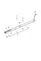
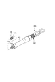
図4-1に、本発明に係るタング無し螺旋状コイルインサート抜取り工具1の一実施例の全体構成を示す。本実施例によると、タング無し螺旋状コイルインサート抜取り工具1は、手動式とされ、マンドレル組立体40を有する。
Example 1
(Overall tool configuration)
FIG. 4-1 shows the overall configuration of an embodiment of the tongueless spiral coil insert extraction tool 1 according to the present invention. According to this embodiment, the tongueless spiral coil insert extraction tool 1 is a manual type and has a
マンドレル組立体40は、マンドレル41を備えている。マンドレル41にはマンドレル駆動ハンドル50が設けられ、手動でマンドレル41を回転駆動するように構成される。駆動ハンドル50でマンドレル41を回転することにより、マンドレル41の先端部を構成するネジ軸45が回転する。このとき、マンドレル駆動ハンドル50でマンドレル41の回転操作を容易にするために、図4-2(b)に示すように、作業者が把持し得る把持管51をマンドレル41に回転自在に装着することができる。把持管51は、例えばマンドレル41に環状溝52を形成しておき、必要に応じてこの溝41に止め輪53を取付けることによりマンドレル41に装着することができる。
The
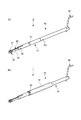
本発明のタング無し螺旋状コイルインサート抜取り工具1は、図5(a)〜(d)に示すように、既に被加工物200に装着されたタング無し螺旋状コイルインサート100を抜取るものであり、従って、タング無し螺旋状コイルインサート抜取り工具1の先端ねじ軸45を、被加工物200に装着されたコイルインサート100の入口側コイル部(即ち、抜取り工具1が接近する被加工物表面側のコイル部)100bに適合し、マンドレル駆動ハンドル50を回転することにより、マンドレル41のネジ軸45が、コイルインサート100の入口側コイル部100bから反端側の他端側コイル部100a方向へと、つまり、コイルインサート内部へと螺入される(図5(a)、(b))。次いで、マンドレル駆動ハンドル50を逆転させると、ねじ軸45は、先ほどとは逆回転し、コイルインサート100から離脱するべくコイルインサート内部から入口側コイル部100b方向へと戻され、爪部81がコイル部100bの切欠き部101に係合し、コイルインサート100が被加工物200から抜取られる。詳しくは後述する。
The tongueless spiral coil insert extraction tool 1 of the present invention is for extracting the tongueless
(マンドレル組立体)
次に、本発明の特徴部を構成するマンドレル組立体40について、図1(a)〜(c)、図2、図3(a)〜(d)及び図4を参照して説明する。
(Mandrel assembly)
Next, a
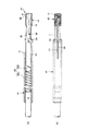
図4を参照して上述したように、マンドレル組立体40は、マンドレル41を備えており、本実施例によれば、マンドレル41は、先端部がネジ軸45とされる。
As described above with reference to FIG. 4, the
更に説明すると、マンドレル41は、図4にて、ネジ軸45が形成された小径軸部42と、この小径軸部42に連接して形成された、外径が小径軸部42より大径とされ、所定の内径を有した管状軸部43とを有している。更に、管状軸部43は、マンドレル駆動ハンドル50が取り付けられた駆動軸部44と一体に接続される。駆動軸部44は、例えば、その小径接手部44aが管状軸部43の内径部に挿入され、ピン44bにて止着される。
More specifically, the
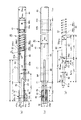
図1(a)、(b)は、マンドレル組立体40を水平に配置した状態を示しており、図1(a)は中央縦断面図であり、図1(b)は平面図である。図1(c)は、枢動爪80の正面図である。
FIGS. 1A and 1B show a state in which the
マンドレル41の小径軸部42は、図1(a)、(b)では左側端部から所定長さLに亘って、タング無し螺旋状コイルインサート100の内径ネジ部(雌ネジ)に螺合し得る雄ネジ70が形成されたネジ軸45とされる。
The small-
本実施例によると、マンドレル41の小径軸部42及び管状軸部43には、マンドレル41の軸線方向に沿って枢動爪80が取り付けられる。枢動爪80の先端面81aは、ネジ軸45の先端面42aより所定距離L45a(ネジ山1〜5個程度)だけ内方へと後退して配置される。ネジ軸45の長さL45aの領域45aは、詳しくは後述するように、ネジ軸45をコイルインサート100に挿入する際のガイド部として機能する。
According to the present embodiment, the
本実施例では、図1(a)、(b)に示すように、マンドレル41の左側端面42aから、長さL42とされる小径軸部42の全域(即ち、L71a(=L42))及び管状軸部43の長さL71bの領域に亘って、長さL71にて軸線方向に一つの枢動爪取付溝71が形成される。小径軸部42においては、小径軸部42の中心方向に深さH、幅Wにて枢動爪取付溝71が形成され、管状軸部43においては、管状軸部43の肉厚部分を貫通して形成される。小径軸部42の枢動爪取付溝71は、図面上左側端部がネジ軸45の端面42aに開口している。
In this embodiment, as shown in FIGS. 1A and 1B, from the
参考のために、一具体的寸法を挙げれば、本実施例では、マンドレル41にて、小径軸部42の長さL42=20mm、ネジ軸45の外径D=5mm、長さL=7mm(L45a=1mm)、とされた。管状軸部43は、長さL43=40mm、内径d43=7mm、外径D43=8mmとし、駆動軸部44の長さL44=53mm(L44a=14mm)、外径D44=8mm(D44a=7mm)とした。枢動爪取付溝71は、長さL71a(=L42)=20mm、L71b=24mm、深さH=4.5mmとした。
For reference, in one specific dimension, in this embodiment, the
枢動爪80は、細長形状部材であって、特に、本実施例では、厚さ(t)=1.3mmの金属製の、例えば鋼製の板部材とされ、この板厚(t)=1.3mmより僅かに大きな幅(W)、例えば、W=1.4〜1.5mmとされる枢動爪取付溝71内に可動に装着される。また、枢動爪80は、長手方向略中央部にて枢動軸受け孔84aを介して枢動軸84にて揺動自在に管状軸部43に取り付けられる。
The
更に説明すると、枢動爪80は、枢動軸84よりも左側の小径軸部42内に位置した作動部82と、枢動軸84よりも右側の管状軸部43内に位置した支持部83とにて構成される。
More specifically, the
作動部82の幅W2は、支持部83の幅W3よりも狭くされている。支持部83は、その幅W3が作動部82との連接部にて最も狭い幅W3minとされ、支持部83の後端領域にて最大の幅W3maxとされる。支持部83の幅W3maxは、作動部82が枢動軸84の回りに揺動し得るように、管状軸部43の内径d43より幾分小さくされる。支持部83の上面83aと管状軸部43の内壁との間には間隙g1が設けられる。また、支持部83の下面83bもまた、後端位置から枢動軸84側へと上方に傾斜した形状とされ、支持部83の下面83bと管状軸部43の内壁との間には、次第に大きくなる空隙g2が形成されている。
The width W2 of the operating
参考のために、一具体的寸法を挙げれば、本実施例では、枢動爪80の全長L80=46mmとされ、枢動爪80の先端(図1にて左側端)から枢動軸受け孔84aまでの作動部82の長さL82=23mm、幅W2=1.53mm、とされ、枢動軸受け孔84aから後端(図1にて右側端)まで支持部83の長さL83=23mm、最大幅W3max=4.5mm、最小幅W3min=3.5mmとされた。また、作動部82は、先端81aより距離L80a=30mmの位置から、支持部83に対して角度θ1=4°にて傾斜している。
For reference, in one specific dimension, in this embodiment, the total length L80 of the
また、作動部82の長さL82a=18.5mm、支持部83の長さL83a=26mmとされる。上記構成により、図1(c)に示すように、作動部82と支持部83との接続部には段差部85が形成され、本例では、この段差部85を形成する角度θ2=120°とされる。従って、段差部85の長さL85は略1.5mmとされる。
Further, the length L82a of the operating
枢動爪80の作動部82の先端81aの領域には、図1にて左側には、上述したように、一旦マンドレル駆動ハンドル50を回転することにより、ネジ軸45が、被加工物に装着されたコイルインサート内部へと螺入した後、マンドレル50を逆転させることによりねじ軸45がコイルインサートから離脱されるとき、タング無し螺旋状コイルインサートの入口側の端部コイル部100aの切欠き101に係合する爪部81が形成されている。即ち、爪部81は、板部材とされる作動部82の先端81aから所定長さL81の板厚端面領域に形成される。爪部81の詳細については後述する。
In the region of the
なお、爪部81は、ネジ軸45の先端面(図1にて左側面)42aから所定の距離L45aだけ後退した位置にその先端面81aが位置している。ネジ軸45の長さL45aの領域45aは、コイルインサート抜取り工具1にて被加工物に装置されたコイルインサート100を抜き取る作業を行う際に、先ず、その先端ネジ軸45を、コイルインサート100の入口部領域の1〜5個程度の雌ネジのネジ山(通常、1〜2山程度でも良い)に螺入させるためのガイド部として機能する。従って、ガイド部としての機能を増大させるために、本例では、上述したマンドレル41の形状寸法にて、小径軸部42の長さL42は20mmから26mm、長さLは7mmから13mm(L45aは1mmから6mm)程度にまで大きくすることができる。
The
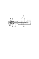
なお、別法として、図2に示すように、ネジ軸45の先端領域L70aのネジ山を削除し、単に、ネジ軸45の軸線方向に外方へと突出し、被加工物に装置されたコイルインサート100の内径部に嵌合する軸状のガイド部としても良い。
As an alternative, as shown in FIG. 2, the screw thread in the tip region L70a of the
このように、ネジ軸45の先端部に、所定長さを有したガイド部としての領域45aを有することにより、抜き取り作業性を向上させることができる。
Thus, by having the area |
一方、枢動爪80の支持部83の後端面(図1にて右側端面)は、図1(a)にて、管状軸部43の内壁面の直角方向の垂線に対して幅方向に所定角度αだけ傾斜した傾斜面87とされる。本実施例では、角度αは、5°とされた。ただし、この値に限定されるものではない。
On the other hand, the rear end surface (right end surface in FIG. 1) of the
図1(c)に示すように、この傾斜面87に付勢手段88からの押圧力(A)が付与され、支持部83の傾斜端面87が下方(B)に押圧されることにより、枢動爪80の爪部81は、上方(C)へと揺動し、タング無し螺旋状コイルインサート100の切欠き101に係止可能とする。また、爪部81が下方に押圧された場合には、傾斜面87は、上方へと可動とされる。
As shown in FIG. 1 (c), the pressing force (A) from the biasing means 88 is applied to the
本実施例では、付勢手段88は、管状軸部43の内部に収納された圧縮コイルバネ88aと、圧縮コイルバネ88aにより枢動爪80の支持部83の傾斜端面87に当接されるバネ受け部材88bと、を備えている。バネ受け部材88bは、段状の短軸部材とされ、圧縮コイルばね88aと当接する大径部88b1と、傾斜端面87に当接する小径部88b2とにて形成される。上述したように、バネ受け部材88bは圧縮コイルバネ88aにより枢動爪80の傾斜端面87に押圧(A)されることにより、枢動爪80の傾斜端面87を、図1(c)にて下方(B)へと押圧する。従って、上述したように、枢動爪80の爪部81をネジ軸45の半径方向外方向(C)へと付勢することとなる。これにより、詳しくは後述するように、爪部81に形成したフック部分90がタング無し螺旋状コイルインサート100の切欠き101に弾発的に係合する。
In this embodiment, the biasing means 88 includes a
勿論、付勢手段88は、上記構成に限定されるものではなく、例えば、バネ受け部材88bの代わりに、図6(a)に示すように、圧縮コイルバネ88aにより枢動爪80の支持部83の傾斜端面87に当接されるボールとすることもできる。
Of course, the biasing means 88 is not limited to the above-described configuration. For example, instead of the
次に、枢動爪80の爪部81について説明する。
Next, the
上述したように、本発明のタング無し螺旋状コイルインサート抜取り工具1は、既に被加工物200に装着されたタング無し螺旋状コイルインサート100を抜取るものであり、従って、図5(a)〜(d)に示すように、タング無し螺旋状コイルインサート抜取り工具1の先端ネジ軸45を、被加工物200に装着されたコイルインサート100の入口側に適合し、マンドレル駆動ハンドル50により回転されると、マンドレル41のネジ軸45が、コイルインサート100の入口側から反端側の他端側へと、つまり、コイルインサート内部へと螺入される。次いで、マンドレル50を逆転させると、ねじ軸45は、先ほどとは逆回転し、コイルインサート内部から入口側へと戻される。
As described above, the tongue-less spiral coil insert extraction tool 1 of the present invention is for extracting the tongue-free
従って、本発明の抜取り工具1は、上述したように、枢動爪80の作動部82の先端部には、図1にて左側には、爪部81が形成されている。この爪部81は、マンドレル駆動ハンドル50を回転することにより、ネジ軸45が被加工物200に装着されたコイルインサート内部へと螺入した後、マンドレル50を逆転させることによりねじ軸45がコイルインサート100から離脱されるとき、タング無し螺旋状コイルインサート100の入口側の端部コイル部100bの切欠き101に係合する。即ち、爪部81は、板部材とされる作動部82の先端81aから所定距離L81の板厚端面領域に形成される。次に、爪部81の詳細について説明する。
Therefore, as described above, the extraction tool 1 of the present invention has the
枢動爪80の爪部81には、フック部分90が形成される。このフック部分90は、図3(a)〜(d)をも参照すると理解されるように、タング無し螺旋状コイルインサート100の抜取り時に、コイルインサート100の入口側、即ち、被加工物200に装着されたコイルインサート100の工具が挿入される側の端部コイル100bの、切欠き101に係止する。
A
爪部81は、枢動爪取付溝部71内でネジ軸45の半径方向に円滑に移動可能とされた所定の形状寸法、即ち、長さL81及び厚さT1、幅W1(即ち、枢動爪80の板厚(t))の概略矩形状板部材とされる。
The
爪部81の上面は、ネジ軸45の外径と略同じか、僅かに半径方向へと突出するように設定されている。爪部81は、その上面をネジ軸45の中心方向へと押圧することにより、支持部83に対する付勢手段88、即ち、圧縮コイルバネ88aの付勢力に抗して取付溝部71内へと押入可能とされる。
The upper surface of the
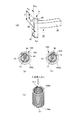
更に、図3(a)を参照して、爪部81について説明する。図3(a)は、本実施例にて使用される爪部81の一実施例を示す。また、図3(d)にタング無し螺旋状コイルインサート100の一例を示す。
Furthermore, the nail | claw
本実施例にて、爪部81の一方の面には、即ち、図3(a)にて手前側の面には、ネジ軸45と共に回転してタング無し螺旋状コイルインサート100へとねじ込まれた後、逆回転時に、図3(b)に示すように、コイルインサート100の入口側端部コイル部100bの切欠き101と弾発的に係止するフック部分90が形成されている。このフック部分90は、コイルインサート100の端部コイル部100b(図3(d)参照)の切欠き101に係合する形状とすることができる。このフック部分90の窪みの深さEは、図3(a)、(b)に示すように、抜取り作業中にコイルインサート100の切欠き101がこの窪み90の中に維持され、窪み凹面と接触し続けるように設定される。
In this embodiment, one surface of the
なお、本実施例では、フック部分90の反対側(後面)には、傾斜部分91が形成されている。この傾斜部分91は、図3(c)に示すように、ネジ軸45を被加工物に装着されているコイルインサート100にねじ込む際に、コイルインサート100の端末コイル部100b(図3(d))が、ネジ軸外周から僅かに突出した爪部81を付勢手段88による付勢力に抗して内方へと押入し、爪部81がネジ軸45内へと円滑に螺入するためのガイド機能をなす。
In the present embodiment, an
参考のために、爪部81の一具体的寸法を挙げれば、本実施例では、図3(a)にて、長さL81=1.6mm、高さT1=2.5mm、幅W1(=t)=1.3mm、とした。また、フック部90の凹み量Eは、0.1〜0.3mm程度とされる。
For reference, if one specific dimension of the
爪部81の形状は、図3(a)を参照して説明した上記実施例に示す構造のものに限定されるものではなく、当業者には他の種々の変更形態が想到されるであろう。
The shape of the
(工具の作動態様及び操作方法)
次に、特に図5(a)、(b)、(c)、(d)をも参照して、上記構成とされる本発明の螺旋状コイルインサート抜取り挿入工具1の作動態様及び操作方法について説明する。
(Tool operation mode and operation method)
Next, with reference to FIGS. 5 (a), (b), (c), and (d) in particular, the operation mode and operation method of the helical coil insert extraction / insertion tool 1 of the present invention configured as described above will be described. explain.
先ず、図5(a)に示すように、螺旋状コイルインサート抜取り挿入工具1のネジ軸45の先端部を、被加工物200に装着されているコイルインサート100の入口側(即ち、被加工物200の表面側)の端部コイル部100bに対向させる。
First, as shown in FIG. 5A, the tip end of the
次いで、ネジ軸45の先端部をコイルインサート100の入口側端部コイル部100bに適合し、図5(b)に示すように、マンドレル駆動ハンドル50を矢印で示す所定の方向(ここでは、工具側からコイルインサート側を見て時計方向)に回転させる。これにより、図5(b)に示すように、先ず、ネジ軸45の先端ガイド部45a(例えば1〜2山程度)がコイルインサート100の内周ネジ部に螺合する。更にマンドレル駆動ハンドル50を回転することにより、ネジ軸45は、コイルインサート100の他端側コイル部100aの方向へと、即ち、コイルインサート100の内部へと螺入し、ネジ軸45に設置された爪部81のフック部90が螺旋状コイルインサート100の入口側端部コイル部100bの切欠き101に至る。
Next, the tip end portion of the
勿論、ネジ軸先端ガイド部45aに、図2に示すように、ネジ山が形成されていない場合には、ネジ軸45の先端ガイド部45aを、図5(b)に示すように、コイルインサート100の入口側端部コイル部100bに適合し、そして、コイルインサート100の内部へと挿入する。次いで、マンドレル駆動ハンドル50を矢印で示す所定の方向(時計方向)に回転させる。これにより、ネジ軸45の先端ネジ山がコイルインサート100の内周ネジ部に螺合し始める。更にマンドレル駆動ハンドル50を回転することにより、ネジ軸45は、コイルインサート100の他端側コイル部100aの方向へと、即ち、コイルインサート100の内部へと螺入し、ネジ軸45に設置された爪部81のフック部90が螺旋状コイルインサート100の先端コイル部100bの切欠き101に至る。
Of course, when the screw shaft
上記いずれの場合であっても、更に、マンドレル駆動ハンドル50を所定の方向(時計方向)に回転させることにより、図3(c)に示すように、フック部分90の反対側(後面)に形成された傾斜部分91がコイルインサート100の端末コイル部100bに突き当たることにより、ネジ軸外周から僅かに突出した爪部81を付勢手段88による付勢力に抗して内方へと押入し、爪部81がネジ軸45内へと円滑に螺入される。
In any of the above cases, the mandrel drive handle 50 is further rotated in a predetermined direction (clockwise) to form on the opposite side (rear surface) of the
フック部ネジ軸45の略全体がコイルインサート100内へと螺入された時点で、即ち、爪部81がコイルインサート100の内部へと、少なくともコイルインサート100の2〜3山以上の雌ネジ山位置に位置させる。
When almost the entire hook
この状態で、図5(c)に示すように、マンドレル駆動ハンドル50の回転を矢印で示す逆方向(反時計方向)に回転させると、ネジ軸45は、コイルインサート100から離脱方向、即ち、コイルインサート100の入口側端部コイル部100b方向へと移動する。そして、ネジ軸45に設置された爪部81のフック部90が螺旋状コイルインサート100の先端コイル部100bの切欠き101に至る。爪部81は、図3(b)に示すように、タング無し螺旋状コイルインサート100の入口側の端部コイル部の切欠き101に係合する。従って、マンドレル駆動ハンドル50の回転を継続して行うことにより、爪部81のフック部90によりタング無し螺旋状コイルインサート100を逆回転させ、それにより、螺旋状コイルインサート100は、図5(d)に示すように、被加工物200から除去される。
In this state, as shown in FIG. 5C, when the rotation of the mandrel drive handle 50 is rotated in the reverse direction (counterclockwise direction) indicated by the arrow, the
本実施例によると、螺旋状コイルインサート100を被加工物200から作業性良く抜取ることができる。
According to this embodiment, the
上記実施例では、本発明が手動式のタング無し螺旋状コイルインサート抜取り工具である場合について説明したが、本発明は、電動式のタング無し螺旋状コイルインサート抜取りにも同様に適用し、同様の作用効果を得ることができる。本発明の特徴部を除いた、電動式の螺旋状コイルインサート抜取り工具の全体構成は、当業者には周知である。従って、更に詳しい説明は省略する。 In the above embodiment, the case where the present invention is a manual tangless spiral coil insert extraction tool has been described. However, the present invention is similarly applied to an electric tangless spiral coil insert extraction tool. An effect can be obtained. The overall configuration of the electric helical coil insert extraction tool, excluding the features of the present invention, is well known to those skilled in the art. Therefore, further detailed description is omitted.
1 螺旋状コイルインサート抜取り工具
40 マンドレル組立体
41 マンドレル
42 小径軸部
43 管状軸部
44 駆動軸部
45 マンドレルネジ軸
45a ガイド部
70 雄ネジ
71 枢動爪取付溝
80 枢動爪
81 爪部
82 作動部
83 支持部
84 枢動軸
85 段差
86 切り欠き凹部
87 傾斜端面
88 付勢手段
88a 圧縮コイルバネ
88b バネ受け部材
90 フック部分
DESCRIPTION OF SYMBOLS 1 Spiral coil
Claims (4)
細長形状部材であって、一端に前記タング無し螺旋状コイルインサートの前記被加工物の表面側に位置した端部コイル部の切欠きに係合する爪部を備えた作動部と、前記作動部と一体に形成された支持部とを備えた枢動爪と、
を有するタング無し螺旋状コイルインサート抜取り工具であって、
前記マンドレルは、前記ネジ軸が形成された小径軸部と、前記小径軸部に連接して形成された外径が前記小径軸部より大径とされる細長筒形状の管状軸部とを有し、
前記小径軸部及び前記管状軸部には、前記枢動爪を設置するために、前記小径軸部の端面から前記マンドレルの軸線方向に所定長さに亘って枢動爪取付溝が形成され、
前記枢動爪は、前記枢動爪取付溝に装着され、且つ、前記支持部が枢動軸にて揺動自在に前記マンドレルに取り付けられ、
前記管状軸部には、前記枢動爪の前記支持部に作用する付勢手段を備え、
前記付勢手段は、前記支持部に作用して、前記爪部に形成したフック部分が前記タング無し螺旋状コイルインサートの前記被加工物の表面側に位置した端部コイル部の前記切欠きに弾発的に係合するように、前記爪部を前記ネジ軸の半径方向外方向へと付勢していることを特徴とするタング無し螺旋状コイルインサート抜取り工具。 A mandrel whose tip is a screw shaft in order to remove the helical coil insert without tongue attached to the workpiece from the workpiece;
An operating part comprising a claw part which engages with a notch of an end coil part located on the surface side of the workpiece of the non-tang helical coil insert at one end; A pivoting claw comprising a support part formed integrally with
A tongueless spiral coil insert extraction tool having
The mandrel has a small-diameter shaft portion on which the screw shaft is formed, and an elongated cylindrical tubular shaft portion whose outer diameter is formed to be connected to the small-diameter shaft portion and is larger in diameter than the small-diameter shaft portion. And
In order to install the pivot claw in the small diameter shaft portion and the tubular shaft portion, a pivot claw attachment groove is formed over a predetermined length from the end surface of the small diameter shaft portion in the axial direction of the mandrel,
The pivot claw is attached to the pivot claw attachment groove, and the support portion is pivotally attached to the mandrel with a pivot shaft,
The tubular shaft portion includes a biasing means that acts on the support portion of the pivot claw,
The biasing means acts on the support portion, and a hook portion formed on the claw portion is formed in the notch of the end coil portion located on the surface side of the workpiece of the tongueless spiral coil insert. A tongueless spiral coil insert extraction tool characterized in that the claw portion is urged radially outward of the screw shaft so as to be elastically engaged.
Priority Applications (19)
| Application Number | Priority Date | Filing Date | Title |
|---|---|---|---|
| JP2012122457A JP5815471B2 (en) | 2012-05-29 | 2012-05-29 | Tongue-free spiral coil insert extraction tool |
| CN201380022437.9A CN104284756B (en) | 2012-05-29 | 2013-05-20 | Without caudal peduncle helical coil swivel nut drawer |
| CA2870528A CA2870528C (en) | 2012-05-29 | 2013-05-20 | Extraction tool for tangless spiral coil insert |
| PL13797722T PL2857148T3 (en) | 2012-05-29 | 2013-05-20 | Tangless helical coil insert removing tool |
| US14/403,766 US9421676B2 (en) | 2012-05-29 | 2013-05-20 | Extraction tool for tangless spiral coil insert |
| SG11201405383PA SG11201405383PA (en) | 2012-05-29 | 2013-05-20 | Extraction tool for tangless spiral coil insert |
| AU2013268604A AU2013268604B2 (en) | 2012-05-29 | 2013-05-20 | Tangless helical coil insert removing tool |
| ES13797722.9T ES2623713T3 (en) | 2012-05-29 | 2013-05-20 | Tangle-free helical insert removal tool |
| RU2014153543A RU2636339C2 (en) | 2012-05-29 | 2013-05-20 | Extractor for spiral threaded insert without trunnion |
| EP13797722.9A EP2857148B1 (en) | 2012-05-29 | 2013-05-20 | Tangless helical coil insert removing tool |
| NZ700286A NZ700286A (en) | 2012-05-29 | 2013-05-20 | Tangless helical coil insert removing tool |
| MYPI2014002715A MY166483A (en) | 2012-05-29 | 2013-05-20 | Extraction tool for tangless spiral coil insert |
| MX2014014640A MX349443B (en) | 2012-05-29 | 2013-05-20 | Tangless helical coil insert removing tool. |
| PCT/JP2013/064552 WO2013180039A1 (en) | 2012-05-29 | 2013-05-20 | Tangless helical coil insert removing tool |
| KR1020147033552A KR101963929B1 (en) | 2012-05-29 | 2013-05-20 | Tangless helical coil insert removing tool |
| BR112014027312-0A BR112014027312B1 (en) | 2012-05-29 | 2013-05-20 | EXTRACTION TOOL FOR A SPINDLESS SPIRAL COIL INSERT |
| TW102117727A TWI542453B (en) | 2012-05-29 | 2013-05-20 | No tail spiral coil sheathing tool |
| IN2289KON2014 IN2014KN02289A (en) | 2012-05-29 | 2014-10-20 | |
| HK15103125.5A HK1202490A1 (en) | 2012-05-29 | 2015-03-27 | Tangless helical coil insert removing tool |
Applications Claiming Priority (1)
| Application Number | Priority Date | Filing Date | Title |
|---|---|---|---|
| JP2012122457A JP5815471B2 (en) | 2012-05-29 | 2012-05-29 | Tongue-free spiral coil insert extraction tool |
Publications (3)
| Publication Number | Publication Date |
|---|---|
| JP2013244591A true JP2013244591A (en) | 2013-12-09 |
| JP2013244591A5 JP2013244591A5 (en) | 2015-07-16 |
| JP5815471B2 JP5815471B2 (en) | 2015-11-17 |
Family
ID=49673235
Family Applications (1)
| Application Number | Title | Priority Date | Filing Date |
|---|---|---|---|
| JP2012122457A Active JP5815471B2 (en) | 2012-05-29 | 2012-05-29 | Tongue-free spiral coil insert extraction tool |
Country Status (19)
| Country | Link |
|---|---|
| US (1) | US9421676B2 (en) |
| EP (1) | EP2857148B1 (en) |
| JP (1) | JP5815471B2 (en) |
| KR (1) | KR101963929B1 (en) |
| CN (1) | CN104284756B (en) |
| AU (1) | AU2013268604B2 (en) |
| BR (1) | BR112014027312B1 (en) |
| CA (1) | CA2870528C (en) |
| ES (1) | ES2623713T3 (en) |
| HK (1) | HK1202490A1 (en) |
| IN (1) | IN2014KN02289A (en) |
| MX (1) | MX349443B (en) |
| MY (1) | MY166483A (en) |
| NZ (1) | NZ700286A (en) |
| PL (1) | PL2857148T3 (en) |
| RU (1) | RU2636339C2 (en) |
| SG (1) | SG11201405383PA (en) |
| TW (1) | TWI542453B (en) |
| WO (1) | WO2013180039A1 (en) |
Cited By (2)
| Publication number | Priority date | Publication date | Assignee | Title |
|---|---|---|---|---|
| JP2016117123A (en) * | 2014-12-19 | 2016-06-30 | 株式会社アドバネクス | Tool for tangless coil thread |
| KR20220077848A (en) * | 2020-12-02 | 2022-06-09 | 가부시키가이샤 자노메 | Apparatus for feedind insert |
Families Citing this family (14)
| Publication number | Priority date | Publication date | Assignee | Title |
|---|---|---|---|---|
| DE102011051846B4 (en) * | 2011-07-14 | 2013-01-24 | Böllhoff Verbindungstechnik GmbH | Tool for installing or removing a tangless wire thread insert, method of manufacture therefor and method of manually changing a picking blade of this tool |
| JP5873525B2 (en) * | 2013-09-02 | 2016-03-01 | 株式会社アドバネクス | Tool for tongueless coil thread |
| CN106457492B (en) * | 2014-04-07 | 2020-01-10 | 纽弗雷公司 | Insertion tool |
| AT517753B1 (en) * | 2015-09-15 | 2019-03-15 | Fill Gmbh | Tool and method for mounting threaded inserts |
| CN105171672B (en) * | 2015-10-26 | 2017-03-22 | 新乡巴山航空材料有限公司 | Steel wire threaded sleeve installation tool free of installation handles |
| DE102016114824A1 (en) * | 2016-08-10 | 2018-02-15 | Böllhoff Verbindungstechnik GmbH | Tool for installing or removing a wire thread insert and manufacturing method therefor |
| DE102016125481A1 (en) | 2016-12-22 | 2018-06-28 | Böllhoff Verbindungstechnik GmbH | Installation tool for a wire thread insert |
| CN108705489A (en) * | 2018-07-09 | 2018-10-26 | 江西中烟工业有限责任公司 | A kind of gas spring dismantling device and its operating method for cigarette making and tipping machine |
| CN111037510A (en) * | 2018-10-11 | 2020-04-21 | 九江精密测试技术研究所 | Tool for installing tailless steel wire thread insert |
| JP6690045B1 (en) * | 2019-06-04 | 2020-04-28 | 株式会社三友精機 | Insert insertion tool and insert insertion method |
| CN110315477B (en) * | 2019-08-02 | 2024-05-10 | 天津航天机电设备研究所 | Tail breaking and taking device for installing steel wire threaded sleeve on blind hole |
| DE102020118057B4 (en) | 2020-02-07 | 2024-05-08 | Völkel GmbH | Tool for installing and/or removing a pinless thread insert |
| CN113774734B (en) * | 2021-10-27 | 2023-02-24 | 孔超 | Railway line nylon sleeve pipe pulling device |
| JP7209393B1 (en) * | 2021-12-15 | 2023-01-20 | 株式会社三友精機 | Tongue breaking tool and tongue breaking method |
Family Cites Families (13)
| Publication number | Priority date | Publication date | Assignee | Title |
|---|---|---|---|---|
| SU576210A1 (en) * | 1971-02-22 | 1977-10-15 | Mikhajlets Aleksej V | Appliance for removing a helix off a cylindrical rod |
| SU1007898A1 (en) * | 1982-01-05 | 1983-03-30 | Предприятие П/Я В-2330 | Apparatus for disassembling joint elements |
| US4528737A (en) * | 1984-02-21 | 1985-07-16 | Rexnord Inc. | Adapter for power tool installation of tangless helically coiled insert |
| US4553303A (en) * | 1984-02-21 | 1985-11-19 | Rexnord Inc. | Removal tool for tangless, helically coiled insert |
| US4553302A (en) | 1984-02-21 | 1985-11-19 | Rexnord Inc. | Installation tool, tangless helically coiled insert |
| US5212865A (en) | 1992-07-20 | 1993-05-25 | Usi Corporation | Tool for installation of tanged and tangless wire inserts |
| US5456145A (en) * | 1993-02-16 | 1995-10-10 | Kato Spring Works Company, Ltd. | Installation tool for tangless helically coiled insert |
| US6421899B1 (en) | 1999-09-15 | 2002-07-23 | Emhart Llc | Extraction and adjustment tool for tangless inserts |
| US6704984B2 (en) * | 2001-07-31 | 2004-03-16 | Newfrey Lcc | Prewinder apparatus for installation tools |
| US20100251859A1 (en) * | 2009-04-07 | 2010-10-07 | Steven Gapp | Universal Pawl Component for Open-ended Ratchet Wrench |
| JP5318659B2 (en) | 2009-05-22 | 2013-10-16 | タカタ株式会社 | Air bag, air bag device, and manufacturing method of air bag |
| TWI542452B (en) * | 2010-07-30 | 2016-07-21 | 日本史普魯股份有限公司 | Insertion tool for tangless spiral coil insert |
| JP5656590B2 (en) | 2010-12-02 | 2015-01-21 | 日本スプリュー株式会社 | Tongue-free spiral coil insert insertion tool |
-
2012
- 2012-05-29 JP JP2012122457A patent/JP5815471B2/en active Active
-
2013
- 2013-05-20 WO PCT/JP2013/064552 patent/WO2013180039A1/en active Application Filing
- 2013-05-20 BR BR112014027312-0A patent/BR112014027312B1/en active IP Right Grant
- 2013-05-20 KR KR1020147033552A patent/KR101963929B1/en active IP Right Grant
- 2013-05-20 TW TW102117727A patent/TWI542453B/en active
- 2013-05-20 EP EP13797722.9A patent/EP2857148B1/en active Active
- 2013-05-20 US US14/403,766 patent/US9421676B2/en not_active Expired - Fee Related
- 2013-05-20 PL PL13797722T patent/PL2857148T3/en unknown
- 2013-05-20 SG SG11201405383PA patent/SG11201405383PA/en unknown
- 2013-05-20 MY MYPI2014002715A patent/MY166483A/en unknown
- 2013-05-20 CN CN201380022437.9A patent/CN104284756B/en active Active
- 2013-05-20 MX MX2014014640A patent/MX349443B/en active IP Right Grant
- 2013-05-20 RU RU2014153543A patent/RU2636339C2/en active
- 2013-05-20 NZ NZ700286A patent/NZ700286A/en not_active IP Right Cessation
- 2013-05-20 CA CA2870528A patent/CA2870528C/en active Active
- 2013-05-20 ES ES13797722.9T patent/ES2623713T3/en active Active
- 2013-05-20 AU AU2013268604A patent/AU2013268604B2/en not_active Ceased
-
2014
- 2014-10-20 IN IN2289KON2014 patent/IN2014KN02289A/en unknown
-
2015
- 2015-03-27 HK HK15103125.5A patent/HK1202490A1/en not_active IP Right Cessation
Cited By (3)
| Publication number | Priority date | Publication date | Assignee | Title |
|---|---|---|---|---|
| JP2016117123A (en) * | 2014-12-19 | 2016-06-30 | 株式会社アドバネクス | Tool for tangless coil thread |
| KR20220077848A (en) * | 2020-12-02 | 2022-06-09 | 가부시키가이샤 자노메 | Apparatus for feedind insert |
| KR102630331B1 (en) * | 2020-12-02 | 2024-01-29 | 가부시키가이샤 자노메 | Apparatus for feedind insert |
Also Published As
| Publication number | Publication date |
|---|---|
| NZ700286A (en) | 2016-07-29 |
| AU2013268604B2 (en) | 2017-02-23 |
| CN104284756B (en) | 2016-04-20 |
| ES2623713T3 (en) | 2017-07-12 |
| TWI542453B (en) | 2016-07-21 |
| EP2857148B1 (en) | 2017-04-05 |
| US9421676B2 (en) | 2016-08-23 |
| KR20150017338A (en) | 2015-02-16 |
| BR112014027312A2 (en) | 2017-06-27 |
| AU2013268604A1 (en) | 2014-10-09 |
| CA2870528C (en) | 2018-11-27 |
| MX349443B (en) | 2017-07-28 |
| EP2857148A4 (en) | 2016-03-23 |
| JP5815471B2 (en) | 2015-11-17 |
| SG11201405383PA (en) | 2014-11-27 |
| PL2857148T3 (en) | 2017-09-29 |
| RU2636339C2 (en) | 2017-11-22 |
| RU2014153543A (en) | 2016-07-20 |
| HK1202490A1 (en) | 2015-10-02 |
| CA2870528A1 (en) | 2013-12-05 |
| KR101963929B1 (en) | 2019-03-29 |
| BR112014027312B1 (en) | 2021-09-21 |
| TW201410404A (en) | 2014-03-16 |
| WO2013180039A1 (en) | 2013-12-05 |
| US20150096160A1 (en) | 2015-04-09 |
| MX2014014640A (en) | 2015-02-12 |
| EP2857148A1 (en) | 2015-04-08 |
| MY166483A (en) | 2018-06-27 |
| IN2014KN02289A (en) | 2015-05-01 |
| CN104284756A (en) | 2015-01-14 |
Similar Documents
| Publication | Publication Date | Title |
|---|---|---|
| JP5815471B2 (en) | Tongue-free spiral coil insert extraction tool | |
| KR101841288B1 (en) | Insertion tool for tangless spiral coil insert | |
| US9308660B2 (en) | Plastic pipe cutter | |
| JP2005528991A (en) | Tool receiving chuck that can be used by rotating around the axis | |
| US11982078B2 (en) | Drain cable decoupler tools | |
| EP2987590A1 (en) | Screw clamping device and screw tool | |
| TWI337115B (en) | ||
| US9186783B2 (en) | Automatic bit-changing screwdriver | |
| JP5656590B2 (en) | Tongue-free spiral coil insert insertion tool | |
| JP2015042449A (en) | Mechanical pencil inner core and method for manufacturing the same | |
| JP5412744B2 (en) | Portable tools | |
| JP2004521763A5 (en) | ||
| FR3066941B3 (en) | ELECTRIC TOOL WITH INTERCHANGEABLE TOOL HOLDER AND TOOL HOLDER | |
| JP7625360B2 (en) | What are sockets and how to use them? | |
| JPH11324424A (en) | Insertion guide for key | |
| JPH09207001A (en) | Pipe scraper | |
| JP2004015950A (en) | Copper wire stripper | |
| JP2001287171A (en) | Bearing drawing jig |
Legal Events
| Date | Code | Title | Description |
|---|---|---|---|
| A521 | Request for written amendment filed |
Free format text: JAPANESE INTERMEDIATE CODE: A523 Effective date: 20150522 |
|
| A621 | Written request for application examination |
Free format text: JAPANESE INTERMEDIATE CODE: A621 Effective date: 20150522 |
|
| A871 | Explanation of circumstances concerning accelerated examination |
Free format text: JAPANESE INTERMEDIATE CODE: A871 Effective date: 20150522 |
|
| TRDD | Decision of grant or rejection written | ||
| A975 | Report on accelerated examination |
Free format text: JAPANESE INTERMEDIATE CODE: A971005 Effective date: 20150824 |
|
| A01 | Written decision to grant a patent or to grant a registration (utility model) |
Free format text: JAPANESE INTERMEDIATE CODE: A01 Effective date: 20150901 |
|
| A61 | First payment of annual fees (during grant procedure) |
Free format text: JAPANESE INTERMEDIATE CODE: A61 Effective date: 20150924 |
|
| R150 | Certificate of patent or registration of utility model |
Ref document number: 5815471 Country of ref document: JP Free format text: JAPANESE INTERMEDIATE CODE: R150 |
|
| R250 | Receipt of annual fees |
Free format text: JAPANESE INTERMEDIATE CODE: R250 |
|
| R250 | Receipt of annual fees |
Free format text: JAPANESE INTERMEDIATE CODE: R250 |
|
| R250 | Receipt of annual fees |
Free format text: JAPANESE INTERMEDIATE CODE: R250 |
|
| R250 | Receipt of annual fees |
Free format text: JAPANESE INTERMEDIATE CODE: R250 |
|
| R250 | Receipt of annual fees |
Free format text: JAPANESE INTERMEDIATE CODE: R250 |
|
| R250 | Receipt of annual fees |
Free format text: JAPANESE INTERMEDIATE CODE: R250 |
|
| R250 | Receipt of annual fees |
Free format text: JAPANESE INTERMEDIATE CODE: R250 |