JP2013241907A - Vacuum pump - Google Patents
Vacuum pump Download PDFInfo
- Publication number
- JP2013241907A JP2013241907A JP2012116489A JP2012116489A JP2013241907A JP 2013241907 A JP2013241907 A JP 2013241907A JP 2012116489 A JP2012116489 A JP 2012116489A JP 2012116489 A JP2012116489 A JP 2012116489A JP 2013241907 A JP2013241907 A JP 2013241907A
- Authority
- JP
- Japan
- Prior art keywords
- motor
- pump
- cooling passage
- casing
- housing
- Prior art date
- Legal status (The legal status is an assumption and is not a legal conclusion. Google has not performed a legal analysis and makes no representation as to the accuracy of the status listed.)
- Pending
Links
Images


Classifications
-
- F—MECHANICAL ENGINEERING; LIGHTING; HEATING; WEAPONS; BLASTING
- F04—POSITIVE - DISPLACEMENT MACHINES FOR LIQUIDS; PUMPS FOR LIQUIDS OR ELASTIC FLUIDS
- F04C—ROTARY-PISTON, OR OSCILLATING-PISTON, POSITIVE-DISPLACEMENT MACHINES FOR LIQUIDS; ROTARY-PISTON, OR OSCILLATING-PISTON, POSITIVE-DISPLACEMENT PUMPS
- F04C23/00—Combinations of two or more pumps, each being of rotary-piston or oscillating-piston type, specially adapted for elastic fluids; Pumping installations specially adapted for elastic fluids; Multi-stage pumps specially adapted for elastic fluids
- F04C23/008—Hermetic pumps
-
- F—MECHANICAL ENGINEERING; LIGHTING; HEATING; WEAPONS; BLASTING
- F04—POSITIVE - DISPLACEMENT MACHINES FOR LIQUIDS; PUMPS FOR LIQUIDS OR ELASTIC FLUIDS
- F04C—ROTARY-PISTON, OR OSCILLATING-PISTON, POSITIVE-DISPLACEMENT MACHINES FOR LIQUIDS; ROTARY-PISTON, OR OSCILLATING-PISTON, POSITIVE-DISPLACEMENT PUMPS
- F04C18/00—Rotary-piston pumps specially adapted for elastic fluids
- F04C18/30—Rotary-piston pumps specially adapted for elastic fluids having the characteristics covered by two or more of groups F04C18/02, F04C18/08, F04C18/22, F04C18/24, F04C18/48, or having the characteristics covered by one of these groups together with some other type of movement between co-operating members
- F04C18/34—Rotary-piston pumps specially adapted for elastic fluids having the characteristics covered by two or more of groups F04C18/02, F04C18/08, F04C18/22, F04C18/24, F04C18/48, or having the characteristics covered by one of these groups together with some other type of movement between co-operating members having the movement defined in group F04C18/08 or F04C18/22 and relative reciprocation between the co-operating members
- F04C18/344—Rotary-piston pumps specially adapted for elastic fluids having the characteristics covered by two or more of groups F04C18/02, F04C18/08, F04C18/22, F04C18/24, F04C18/48, or having the characteristics covered by one of these groups together with some other type of movement between co-operating members having the movement defined in group F04C18/08 or F04C18/22 and relative reciprocation between the co-operating members with vanes reciprocating with respect to the inner member
- F04C18/3441—Rotary-piston pumps specially adapted for elastic fluids having the characteristics covered by two or more of groups F04C18/02, F04C18/08, F04C18/22, F04C18/24, F04C18/48, or having the characteristics covered by one of these groups together with some other type of movement between co-operating members having the movement defined in group F04C18/08 or F04C18/22 and relative reciprocation between the co-operating members with vanes reciprocating with respect to the inner member the inner and outer member being in contact along one line or continuous surface substantially parallel to the axis of rotation
-
- F—MECHANICAL ENGINEERING; LIGHTING; HEATING; WEAPONS; BLASTING
- F04—POSITIVE - DISPLACEMENT MACHINES FOR LIQUIDS; PUMPS FOR LIQUIDS OR ELASTIC FLUIDS
- F04C—ROTARY-PISTON, OR OSCILLATING-PISTON, POSITIVE-DISPLACEMENT MACHINES FOR LIQUIDS; ROTARY-PISTON, OR OSCILLATING-PISTON, POSITIVE-DISPLACEMENT PUMPS
- F04C29/00—Component parts, details or accessories of pumps or pumping installations, not provided for in groups F04C18/00 - F04C28/00
- F04C29/04—Heating; Cooling; Heat insulation
- F04C29/045—Heating; Cooling; Heat insulation of the electric motor in hermetic pumps
-
- F—MECHANICAL ENGINEERING; LIGHTING; HEATING; WEAPONS; BLASTING
- F04—POSITIVE - DISPLACEMENT MACHINES FOR LIQUIDS; PUMPS FOR LIQUIDS OR ELASTIC FLUIDS
- F04C—ROTARY-PISTON, OR OSCILLATING-PISTON, POSITIVE-DISPLACEMENT MACHINES FOR LIQUIDS; ROTARY-PISTON, OR OSCILLATING-PISTON, POSITIVE-DISPLACEMENT PUMPS
- F04C29/00—Component parts, details or accessories of pumps or pumping installations, not provided for in groups F04C18/00 - F04C28/00
- F04C29/04—Heating; Cooling; Heat insulation
- F04C29/047—Cooling of electronic devices installed inside the pump housing, e.g. inverters
-
- F—MECHANICAL ENGINEERING; LIGHTING; HEATING; WEAPONS; BLASTING
- F04—POSITIVE - DISPLACEMENT MACHINES FOR LIQUIDS; PUMPS FOR LIQUIDS OR ELASTIC FLUIDS
- F04C—ROTARY-PISTON, OR OSCILLATING-PISTON, POSITIVE-DISPLACEMENT MACHINES FOR LIQUIDS; ROTARY-PISTON, OR OSCILLATING-PISTON, POSITIVE-DISPLACEMENT PUMPS
- F04C29/00—Component parts, details or accessories of pumps or pumping installations, not provided for in groups F04C18/00 - F04C28/00
- F04C29/12—Arrangements for admission or discharge of the working fluid, e.g. constructional features of the inlet or outlet
-
- F—MECHANICAL ENGINEERING; LIGHTING; HEATING; WEAPONS; BLASTING
- F04—POSITIVE - DISPLACEMENT MACHINES FOR LIQUIDS; PUMPS FOR LIQUIDS OR ELASTIC FLUIDS
- F04C—ROTARY-PISTON, OR OSCILLATING-PISTON, POSITIVE-DISPLACEMENT MACHINES FOR LIQUIDS; ROTARY-PISTON, OR OSCILLATING-PISTON, POSITIVE-DISPLACEMENT PUMPS
- F04C2220/00—Application
- F04C2220/10—Vacuum
-
- F—MECHANICAL ENGINEERING; LIGHTING; HEATING; WEAPONS; BLASTING
- F04—POSITIVE - DISPLACEMENT MACHINES FOR LIQUIDS; PUMPS FOR LIQUIDS OR ELASTIC FLUIDS
- F04C—ROTARY-PISTON, OR OSCILLATING-PISTON, POSITIVE-DISPLACEMENT MACHINES FOR LIQUIDS; ROTARY-PISTON, OR OSCILLATING-PISTON, POSITIVE-DISPLACEMENT PUMPS
- F04C25/00—Adaptations of pumps for special use of pumps for elastic fluids
- F04C25/02—Adaptations of pumps for special use of pumps for elastic fluids for producing high vacuum
Abstract
Description
本発明はバキュームポンプに関し、詳しくは吸入口から吸入した気体を圧縮して排気口から排出するポンプ手段と、このポンプ手段を駆動するモータとを備えたバキュームポンプに関する。 The present invention relates to a vacuum pump, and more particularly, to a vacuum pump including a pump unit that compresses gas sucked from a suction port and discharges it from an exhaust port, and a motor that drives the pump unit.
従来、例えば自動車用のブレーキ倍力装置に負圧を供給するためにバキュームポンプが使用されており、このようなバキュームポンプとして、吸入口から吸入した気体を圧縮して排気口から排出するポンプ手段と、このポンプ手段を駆動するモータとを備えたものが知られている(特許文献1)。
このようなバキュームポンプでは、上記モータによって上記ポンプ手段を駆動し、これにより上記吸入口から気体を吸入して倍力装置に負圧を供給し、一方では上記排出口から吸入した気体を排出するようになっている。
Conventionally, for example, a vacuum pump has been used to supply a negative pressure to a brake booster for an automobile, and as such a vacuum pump, a pump means for compressing the gas sucked from the suction port and discharging it from the exhaust port And a motor that drives the pump means is known (Patent Document 1).
In such a vacuum pump, the pump means is driven by the motor, thereby sucking gas from the suction port and supplying negative pressure to the booster, while discharging the sucked gas from the discharge port. It is like that.
ここで、上記ブレーキ用のバキュームポンプは自動車のエンジンルーム内に装着されることから、エンジンルーム内の温度および上記モータ自体が発生する温度によって高温環境下にさらされることとなる。
高温となることによりモータの特性が変化すると、上記ポンプ手段による吸引性能も変化してしまうことから、安定した負圧を供給することができず、また耐久性に影響を及ぼすこととなる。
このため従来のバキュームポンプでは、高温環境下においても作動可能なモータをバキュームポンプに採用しなければならないという問題があった。
このような問題に鑑み、本発明はモータを冷却してモータの性能ひいてはポンプ手段の吸引性能を維持することが可能なバキュームポンプを提供するものである。
Here, since the brake vacuum pump is mounted in the engine room of the automobile, it is exposed to a high temperature environment depending on the temperature in the engine room and the temperature generated by the motor itself.
If the characteristics of the motor change due to the high temperature, the suction performance by the pump means also changes. Therefore, a stable negative pressure cannot be supplied, and the durability is affected.
For this reason, the conventional vacuum pump has a problem that a motor capable of operating even in a high temperature environment must be employed in the vacuum pump.
In view of such a problem, the present invention provides a vacuum pump that can cool a motor and maintain the performance of the motor, and hence the suction performance of the pump means.
すなわち請求項1の発明にかかるバキュームポンプは、吸入口から吸入した気体を圧縮して排気口から排出するポンプ手段と、このポンプ手段を駆動するモータとを備えたバキュームポンプにおいて、
上記モータのモータケーシングを収容するハウジングを設けて、上記モータケーシングの外面とハウジングの内面との間に冷却通路を形成し、上記ポンプ手段の排気口から排出された気体を上記冷却通路に流通させてモータを冷却させることを特徴としている。
That is, a vacuum pump according to the invention of
A housing for housing the motor casing of the motor is provided, a cooling passage is formed between the outer surface of the motor casing and the inner surface of the housing, and the gas discharged from the exhaust port of the pump means is circulated through the cooling passage. The motor is cooled.
上記発明によれば、上記排気口より排出された気体がモータのモータケーシングとハウジングとの間に形成された冷却通路を流通し、上記モータを冷却することでモータの性能ひいてはポンプ手段の吸引性能を維持することができる。 According to the above invention, the gas discharged from the exhaust port flows through the cooling passage formed between the motor casing and the housing of the motor and cools the motor, whereby the performance of the motor, and hence the suction performance of the pump means. Can be maintained.
以下、図示実施例について説明すると、図1はブレーキの倍力装置に負圧を供給するバキュームポンプ1を示しており、自動車のエンジンルーム内に設けられている。
上記バキュームポンプ1は、吸入した気体を圧縮して排出するポンプ手段2と、このポンプ手段2を駆動するモータ3と、上記モータ3を保持するハウジング4とから構成され、上記ポンプ手段2としてはいわゆるベーンポンプを、上記モータ3としてはブラシレスモータをそれぞれ使用している。
Referring to the illustrated embodiment, FIG. 1 shows a
The
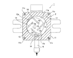
図2に示すように、上記ポンプ手段2は、上面に略円形のポンプ室11aが形成されるとともに下面に上記モータ3が固定されたポンプケーシング11と、上記ポンプケーシング11の上面に設けられて上記ポンプ室11aを閉鎖するカバー12と、上記モータ3によってポンプ室11aの内部で回転するロータ13と、ロータ13の回転に伴ってポンプ室11aを複数の空間に区画する複数枚のベーン14と、上記カバー12の上面を覆うサイレンサー15とから構成されている。
上記ポンプケーシング11は略直方体の部材によって構成され、その上面に形成された上記ポンプ室11aには気体を吸引するための吸入口11bが形成され、上記ポンプ室11aを閉鎖する上記カバー12には圧縮された気体を排出する排気口12aが形成されている。
上記吸入口11bは図2に示すように上記ポンプケーシング11の側面に設けた上記吸入ポート16に連通し、この吸入ポート16は図示しない配管を介して倍力装置に接続されている。
上記排気口12aは図1に示すように上記カバー12に穿設されて圧縮された気体をポンプケーシング11およびカバー12の上方に排出させるようになっており、また図2に示すように上記ロータ13を挟んで上記吸入口11bとは略反対側に形成されている。
As shown in FIG. 2, the pump means 2 is provided on the upper surface of the
The
As shown in FIG. 2, the
As shown in FIG. 1, the
上記ロータ13の中心はポンプ室11aの中心に対して偏心した位置に設けられ、図1に示すように上記モータ3の駆動軸21に連結部材を介して連結され、図2においては反時計回りに回転するようになっている。
また上記ロータ13には直径方向に対して傾斜した角度で等間隔に4つのスリット13aが形成されており、当該スリット13aにはそれぞれ上記ベーン14が出没可能に設けられている。
上記ベーン14は上記スリット13aより出没しながらその先端を上記ポンプ室11aの内周面に接触させ、これにより上記ポンプ室11aを複数の空間に区画するようになっている。
The center of the
Further, the
The
上記サイレンサー15は有底で下端部が開口した箱状の部材であって、開口部の周囲にフランジ15aを備え、当該フランジ15aをポンプケーシング11のカバー12の上面に設けたシール部材に密着させて、このサイレンサー15によって上記カバー12との間に外部より区画されたダンパ空間Sdを形成するようになっている。
また図2に示すように上記ポンプケーシング11の4隅にはボルト孔11cが穿設されており、上記カバー12および上記サイレンサー15の同じ位置に穿設されたボルト孔を貫通するようにボルトを挿通させて、上記カバー12ごとサイレンサー15をポンプケーシング11に固定するようになっている。
さらに、上記ポンプケーシング11およびカバー12には、その上面から下面へと貫通する貫通孔17が形成されており、この貫通孔17の上端は上記サイレンサー15によって形成されたダンパ空間Sdに開口している。
従って、上記カバー12に形成された排気口12aと上記貫通孔17とは上記ダンパ空間Sdを介して相互に連通しており、上記排気口12aより排出された気体は、上記ダンパ空間Sdおよび上記貫通孔17を通過して、ポンプケーシング11の下面側より排出されるようになっている。
The
Further, as shown in FIG. 2,
Further, the
Therefore, the
上記モータ3はいわゆる4極6スロットのブラシレスモータとなっており、上記ポンプ手段2のロータ13に連結された駆動軸21と、モータケーシングとしての円筒状を有するステータコア22と、当該ステータコア22の内部に設けられるとともに上記駆動軸21を囲繞するように配置された6組のコイル23と、上記ステータコア22の外部に設けられて上記コイル23を制御する基板24とを備えている。
また上記ハウジング4は本実施例において上記モータ3の一部を構成しており、上記ポンプケーシング11に密着して駆動軸21の先端側を軸支する第1部材25と、当該第1部材25の下部に設けられて上記ステータコア22を保持する第2部材26と、当該第2部材26の下部に設けられて駆動軸21の後端側を軸支する第3部材27と、当該第3部材27の下面に設けられて上記基板24を収容する第4部材28とから構成されている。
上記第1部材25ないし第3部材27を組み合わせると、その内部には空間が形成されるようになっており、また上記第4部材28は有底で上面が開口した箱状の部材となっており、上記第3部材27との間に空間が形成されるようになっている。
そして、第1〜第4部材25〜28の4隅には上記ポンプケーシング11に形成されたボルト孔11cと同じ位置にボルト孔が形成されており、ボルトによりポンプ手段2の下面に上記モータ3ごと第1〜第4部材25〜28が固定されるようになっている。
The
The
When the
Bolt holes are formed at the same positions as the
上記駆動軸21は、図1において上下に突出する小径部21aと、上記コイル23の位置に合わせて形成された大径部21bとから構成され、上記ハウジング4の第1、第3部材25、27には上記小径部21aを軸支する軸受29が設けられ、上記大径部21bの外周面には互いに磁極が異なるように配置された4つの永久磁石30が固定されている。
上記ステータコア22は筒状を有しており、図1に示すようにその上端および下端が上記ハウジング4の第1部材25および第3部材27によって挟持されている。これにより、ステータコア22の内部、すなわち駆動軸21の設けられた空間は外部から区画されるようになっている。
またステータコア22の内部にはステータとして6個の突起22aが形成されており、上記駆動軸21の外周面と突起22aの内周面との間には若干の隙間が形成されている。
そして上記突起22aに上記コイル23がそれぞれ巻回されており、各コイル23は図示しない配線により上記基板24に接続され、当該基板24の制御によって、各コイル23は磁界を発生させるようになっている。
The
The
The
The
本実施例では、図1、図3に示すようにステータコア22の中心が上記ハウジング4に対して若干図示左方に偏倚しており、上記ステータコア22における図示右方の外周面のみがハウジング4の内部に露出し、それ以外の部分は上記第2部材26が密着することで、グステータコア22が移動しないように保持されている。
そして、このステータコア22の外面とハウジング4の内面との間に形成された空間は、冷却通路Scを構成する第1冷却通路Sc1を形成し、図1、図3に示すように上記ポンプ手段2のポンプケーシング11に形成した貫通孔17と連通している。
また、上記ハウジング4における第2部材26の底面および第3部材27には、破線で示す連通口31が形成されており、上記第3部材27と第4部材28とによって形成された上記冷却通路Scを構成する第2冷却通路Sc2に連通している。
上記連通口31は、上記図示上方の貫通孔17の連通位置に対して図示下方に形成されており、連通口31を上記第1冷却通路Sc1において貫通孔17の略反対側に設けることで、第1冷却通路Sc1の内部を流通する気体が上記ステータコア22の外面に沿って流通するようになっている。
そして、上記第4部材28には図1に示すように側面に排出口28aが形成され、これにより上記第2冷却通路Sc2を流通した気体はこの排出口28aより排出されるようになっている。
そして、本実施例におけるバキュームポンプ1において、上記ポンプ手段2に形成された上記排気口12aの径は、その他の上記貫通孔17、上記ハウジング4に形成された上記連通口31および排出口28aよりも小径となっている。
In the present embodiment, as shown in FIGS. 1 and 3, the center of the
The space formed between the outer surface of the
A
The
As shown in FIG. 1, the
In the
以上、上記構成を有するバキュームポンプ1の動作について説明すると、上記モータ3を構成する基板24を介してコイル23に電流を印加すると、当該コイル23に磁界が発生して上記駆動軸21に設けた永久磁石30が相互に接近または離隔し、これにより駆動軸21が回転する。
ポンプ手段2では、上記駆動軸21に連結されたロータ13が上記ポンプケーシング11に形成されたポンプ室11aで図1の反時計回りに回転し、これによりベーン14がポンプ室11aを複数の空間に区画させた状態で移動する。
上記ロータ13の回転に伴って、上記ベーン14によって区画された空間が上記ポンプ室11aに形成された吸入口11bを通過する際、当該空間はその後ロータ13の回転に伴って徐々に容積が増加することから、上記吸入口11bから気体が吸引され、上記吸入ポート16を介して倍力装置に負圧が供給される。
その後、上記ベーン14によって区画された空間は上記排気口12aに向けてさらに容積が縮小するため、当該空間が排気口12aに連通すると、圧縮された気体が当該排出口28aより排出されるようになっている。
The operation of the
In the pump means 2, the
As the
Thereafter, since the volume of the space partitioned by the
排出口28aより排出された気体は、上記サイレンサー15によって形成されたダンパ空間Sdに流入し、これによりバキュームポンプ1が発生させる騒音が低減されるようになっている。
またダンパ空間Sdを流通した気体は上記ポンプケーシング11およびカバー17に形成された貫通孔17を流通した後、上記ハウジング4に形成された冷却通路Scのうち第1冷却通路Sc1内に流入する。
このとき、上記排気口12aの径は上記貫通孔17の径よりも小径となっているため、上記排気口12aでの排気抵抗に比べて、上記ダンパ空間Sdの気体が貫通孔17に流入する際の排気抵抗は小さくなっており、上記ポンプ手段2の吸気性能を低下させないようになっている。
The gas discharged from the
The gas flowing through the damper space Sd flows through the through
At this time, since the diameter of the
ここで、上記モータ3のコイル23は常時印加される電流によって発熱しており、伝熱によってこのコイル23の巻回された上記突起22aの形成されたステータコア22も温度が上昇することとなる。
上記貫通孔17より第1冷却通路Sc1に流入した気体は、上記第3部材27に形成された連通口31に向けて流通し、その際気体は上記ステータコア22の表面に沿って流通することから、ステータコア22および当該ステータコア22の内部に保持されたコイル23が冷却される。
そして第1冷却通路Sc1を流通した気体は、上記連通口31を介して上記第2冷却通路Sc2へと排出され、その際も上記排気口12aの径は上記連通口31の径よりも小径となっているため、上記排気口12aでの排気抵抗に比べて、上記第1冷却通路Sc1の気体が連通口31に流入する際の排気抵抗は小さくなっている。
上記第2冷却通路Sc2には、上記連通口31の前方に上記基板24が配置されていることから、上記連通口31より流入した気体は直接基板24に吹き付けられ、当該基板24が効率的に冷却されるようになっている。
その後、気体は第4部材28に形成されて上記連通口31より離隔した位置に形成された排出口28aより排出され、その際も上記排気口12aの径は上記排出口28aの径よりも小径となっているため、上記排気口12aの排気抵抗に比べて、上記第1冷却通路Sc1の気体が排出口28aより排出される際の排気抵抗は小さくなっている。
Here, the
The gas flowing into the first cooling passage Sc1 from the through
The gas flowing through the first cooling passage Sc1 is discharged to the second cooling passage Sc2 through the
Since the
Thereafter, the gas is discharged from the
このように、本実施例におけるバキュームポンプ1によれば、上記モータ3のステータコア22の外面と上記ハウジング5の内面との間に形成した冷却通路Scに、上記ポンプ手段2の排気口12aより排出された気体を流通させることで、当該気体によりモータ3を冷却することが可能となっている。
このため、従来に比べて耐熱性の低いモータ3を用いたとしても、安定性を損なわずにバキュームポンプ1を作動させることが可能となり、バキュームポンプ1を安価に得ることが可能となる。
また、本実施例ではモータ3としてブラシレスモータ3を使用しているが、このブラシレスモータ3は上記ステータコア22の内周面に近接した位置に発熱するコイル23を備えているため、この発熱するコイル23を効率的に冷却することができる。
その際、気体はステータコア22における駆動軸21側の空間には流入しないため、ステータコア22の内部における駆動軸21の回転部分に異物が入り込むことはなく、異物によるモータ22の異常発生を防止することができる。
さらに、上記ブラシレスモータ3には基板24が必要となるが、この基板24も上記冷却通路Scに設けて上記気体により冷却しており、ブラシレスモータ3の問題点である基板24の耐熱性も解消することができる。
そして、本実施例では上記冷却通路Scを上記ステータコア22を冷却するための第1冷却通路Sc1と、基板24を冷却するための第2冷却通路Sc2とを設けているため、基板24をこの第2冷却通路Sc2で別途冷却することが可能となっている。
また上記ポンプ手段2にはダンパ空間Sdを形成するサイレンサー15を設けることで、上記気体の排出に伴う騒音を低減することができ、またポンプケーシング11に貫通孔17を形成したことで、外部に新たな配管を設けずに気体を上記冷却通路Scに供給することが可能となっている。
その際、上記排出口28aの径は上記貫通孔17の径よりも小径となっているため、貫通孔17に流入する際の排気抵抗は上記排出口28aより排出される気体の排気抵抗よりも小さく、上記貫通孔17を気体が流通することによるポンプ手段2の効率が低下することもない。
Thus, according to the
For this reason, even if the
In this embodiment, the
At this time, since the gas does not flow into the space on the
Further, the
In this embodiment, the cooling passage Sc is provided with a first cooling passage Sc1 for cooling the
Further, by providing the pump means 2 with a
At this time, since the diameter of the
なお、上記実施例において図3に示すように上記ステータコア22はその一部だけが冷却通路Scに露出しているが、上記ハウジング5の形状を異ならせることにより、ステータコア22の全周を囲繞する冷却通路を形成してもよい。
また上記実施例の図1において、上記第2部材26における上記ステータコア22との接触部分に、上記冷却通路Scに連通するように円周方向に溝を形成し、この溝も冷却通路Scとして気体を流通させるようにすることもできる。
さらに、上記ハウジング4を構成する第4部材28については、これを上記第1部材25とポンプケーシング11との間に設け、当該第4部材28の内部に上記実施例と同様、上記基板24を収容する構成としてもよい。
この場合、気体は上記貫通孔17は第4部材28に形成された第2冷却通路Sc2に流入した後、例えば第1部材25と第4部材28との間に形成した連通口31を介して第1冷却通路Sc1に流入し、ステータコア22を冷却することができる。
一方、上記実施例では気体を上記ハウジング5における第4部材28に流入させて基板を冷却しているが、上記連通口31を省略するとともに上記第2部材26に排出口を形成することで、ステータコア22だけを冷却して基板24については冷却しないようにすることもできる。
そして、上記実施例における上記モータ3をいわゆるブラシモータとしてもよく、ブラシモータであってもハウジングの内部に露出したモータケーシングを冷却することによってモータ3全体を冷却することが期待できる。
In the above embodiment, as shown in FIG. 3, only a part of the
Further, in FIG. 1 of the above-described embodiment, a groove is formed in the circumferential direction so as to communicate with the cooling passage Sc at the contact portion of the
Further, the
In this case, the gas passes through the
On the other hand, in the above embodiment, gas is allowed to flow into the
And the said
1 バキュームポンプ 2 ポンプ手段
3 モータ 4 ハウジング
11 ポンプケーシング 11a ポンプ室
11b 吸入口 12 カバー
12a 排気口 15 サイレンサー
21 駆動軸 22 ステータコア(モータケーシング)
Sd ダンパ空間 Sc 冷却通路
Sc1 第1冷却通路 Sc2 第2冷却通路
DESCRIPTION OF
Sd Damper space Sc Cooling passage Sc1 First cooling passage Sc2 Second cooling passage
Claims (4)
上記モータのモータケーシングを収容するハウジングを設けて、上記モータケーシングの外面とハウジングの内面との間に冷却通路を形成し、上記ポンプ手段の排気口から排出された気体を上記冷却通路に流通させてモータを冷却させることを特徴とするバキュームポンプ。 In a vacuum pump comprising pump means for compressing the gas sucked from the suction port and discharging it from the exhaust port, and a motor for driving the pump means,
A housing for housing the motor casing of the motor is provided, a cooling passage is formed between the outer surface of the motor casing and the inner surface of the housing, and the gas discharged from the exhaust port of the pump means is circulated through the cooling passage. Vacuum pump characterized by cooling the motor.
上記基板を上記冷却通路の内部に配置したことを特徴とする請求項1に記載のバキュームポンプ。 The motor is a brushless motor, and includes a plurality of sets including a drive shaft including a permanent magnet and connected to the pump means, and a stator core serving as the motor casing and surrounding the drive shaft. A coil and a substrate that is provided outside the stator core and controls the coil;
The vacuum pump according to claim 1, wherein the substrate is disposed inside the cooling passage.
上記ポンプ手段における排気口の径を、上記連通口の径よりも小径としたことを特徴とする請求項2に記載のバキュームポンプ。 The cooling passage includes a first cooling passage formed between an inner surface of the housing and an outer surface of the stator core, a second cooling passage that is partitioned with respect to the first cooling passage and accommodates the substrate, and A communication port that communicates the first cooling passage with the second cooling passage;
The vacuum pump according to claim 2, wherein the diameter of the exhaust port in the pump means is smaller than the diameter of the communication port.
上記ポンプケーシングに一方の端面から他方の端面へと貫通する貫通孔を形成し、さらに当該貫通孔を上記ハウジングに形成された冷却通路と連通するように設け、
さらに、上記ポンプケーシングにおける上記一方の端面側に、上記排気口と貫通孔とを連通させるダンパ空間を形成するサイレンサーを設けて、
上記排気口より排出された空気を、上記ダンパ空間および上記貫通孔を介して上記冷却通路へと流入させることを特徴とする請求項1ないし請求項3のいずれかに記載のバキュームポンプ。 The pump means includes a pump casing in which a substantially circular pump chamber is formed on one end surface and the motor is fixed to the other end surface, and a pump casing formed on one end surface of the pump casing to close the pump chamber. And a cover formed with the exhaust port, a rotor that is rotated inside the pump chamber by the motor, and a vane that divides the pump chamber into a plurality of spaces as the rotor rotates,
Forming a through hole penetrating from one end surface to the other end surface of the pump casing, and further providing the through hole in communication with a cooling passage formed in the housing;
Furthermore, a silencer is provided on the one end face side of the pump casing to form a damper space for communicating the exhaust port and the through hole.
The vacuum pump according to any one of claims 1 to 3, wherein the air discharged from the exhaust port flows into the cooling passage through the damper space and the through hole.
Priority Applications (3)
| Application Number | Priority Date | Filing Date | Title |
|---|---|---|---|
| JP2012116489A JP2013241907A (en) | 2012-05-22 | 2012-05-22 | Vacuum pump |
| PCT/JP2013/063629 WO2013176028A1 (en) | 2012-05-22 | 2013-05-16 | Vacuum pump |
| EP13793663.9A EP2853748A4 (en) | 2012-05-22 | 2013-05-16 | Vacuum pump |
Applications Claiming Priority (1)
| Application Number | Priority Date | Filing Date | Title |
|---|---|---|---|
| JP2012116489A JP2013241907A (en) | 2012-05-22 | 2012-05-22 | Vacuum pump |
Publications (1)
| Publication Number | Publication Date |
|---|---|
| JP2013241907A true JP2013241907A (en) | 2013-12-05 |
Family
ID=49623722
Family Applications (1)
| Application Number | Title | Priority Date | Filing Date |
|---|---|---|---|
| JP2012116489A Pending JP2013241907A (en) | 2012-05-22 | 2012-05-22 | Vacuum pump |
Country Status (3)
| Country | Link |
|---|---|
| EP (1) | EP2853748A4 (en) |
| JP (1) | JP2013241907A (en) |
| WO (1) | WO2013176028A1 (en) |
Cited By (6)
| Publication number | Priority date | Publication date | Assignee | Title |
|---|---|---|---|---|
| JP2015175343A (en) * | 2014-03-18 | 2015-10-05 | 大豊工業株式会社 | Fluid machinery |
| KR20160082606A (en) * | 2014-12-26 | 2016-07-08 | 영신정공 주식회사 | ELECTRO VACUUM PUMP to reduce the Noise |
| JP2017040181A (en) * | 2015-08-18 | 2017-02-23 | 大豊工業株式会社 | Motor pump |
| JP2017040182A (en) * | 2015-08-18 | 2017-02-23 | 大豊工業株式会社 | Motor pump |
| JP2017510753A (en) * | 2014-04-11 | 2017-04-13 | マグナ パワートレイン ヒュッケスヴァーゲン ゲーエムベーハー | Automotive vacuum pump with adhesive |
| KR101852384B1 (en) * | 2018-02-07 | 2018-06-04 | 서중 | Cooling plate use dry type vacuum pump |
Families Citing this family (2)
| Publication number | Priority date | Publication date | Assignee | Title |
|---|---|---|---|---|
| US11261869B2 (en) * | 2016-06-22 | 2022-03-01 | Pierburg Pump Technology Gmbh | Motor vehicle vacuum pump arrangement |
| JP7161918B2 (en) * | 2018-11-06 | 2022-10-27 | 株式会社ミクニ | vacuum pump |
Citations (6)
| Publication number | Priority date | Publication date | Assignee | Title |
|---|---|---|---|---|
| JPS6293496A (en) * | 1985-10-18 | 1987-04-28 | Hitachi Ltd | Rotary vane type pump |
| WO2006124509A2 (en) * | 2005-05-12 | 2006-11-23 | Sullair Corporation | Integrated electric motor driven compressor |
| JP2007023958A (en) * | 2005-07-20 | 2007-02-01 | Matsushita Electric Ind Co Ltd | Vane rotary type air pump |
| JP2008101558A (en) * | 2006-10-20 | 2008-05-01 | Hitachi Appliances Inc | Hermetic compressor |
| JP4519490B2 (en) * | 2004-03-18 | 2010-08-04 | 日立アプライアンス株式会社 | Scroll compressor |
| JP2011007110A (en) * | 2009-06-25 | 2011-01-13 | Daikin Industries Ltd | Compressor |
Family Cites Families (6)
| Publication number | Priority date | Publication date | Assignee | Title |
|---|---|---|---|---|
| JP2639136B2 (en) * | 1989-11-02 | 1997-08-06 | 松下電器産業株式会社 | Scroll compressor |
| JPH04187891A (en) | 1990-11-20 | 1992-07-06 | Fuji Electric Co Ltd | Silencer for vane pump |
| JP2004156446A (en) * | 2002-11-01 | 2004-06-03 | Tokico Ltd | Scroll fluid-machinery |
| JP4629546B2 (en) * | 2005-09-30 | 2011-02-09 | アネスト岩田株式会社 | Scroll fluid machinery |
| CN101346548B (en) * | 2005-12-28 | 2010-08-11 | 大金工业株式会社 | Compressor |
| DE102006058843A1 (en) * | 2006-12-13 | 2008-06-19 | Pfeiffer Vacuum Gmbh | vacuum pump |
-
2012
- 2012-05-22 JP JP2012116489A patent/JP2013241907A/en active Pending
-
2013
- 2013-05-16 WO PCT/JP2013/063629 patent/WO2013176028A1/en active Application Filing
- 2013-05-16 EP EP13793663.9A patent/EP2853748A4/en not_active Withdrawn
Patent Citations (6)
| Publication number | Priority date | Publication date | Assignee | Title |
|---|---|---|---|---|
| JPS6293496A (en) * | 1985-10-18 | 1987-04-28 | Hitachi Ltd | Rotary vane type pump |
| JP4519490B2 (en) * | 2004-03-18 | 2010-08-04 | 日立アプライアンス株式会社 | Scroll compressor |
| WO2006124509A2 (en) * | 2005-05-12 | 2006-11-23 | Sullair Corporation | Integrated electric motor driven compressor |
| JP2007023958A (en) * | 2005-07-20 | 2007-02-01 | Matsushita Electric Ind Co Ltd | Vane rotary type air pump |
| JP2008101558A (en) * | 2006-10-20 | 2008-05-01 | Hitachi Appliances Inc | Hermetic compressor |
| JP2011007110A (en) * | 2009-06-25 | 2011-01-13 | Daikin Industries Ltd | Compressor |
Cited By (8)
| Publication number | Priority date | Publication date | Assignee | Title |
|---|---|---|---|---|
| JP2015175343A (en) * | 2014-03-18 | 2015-10-05 | 大豊工業株式会社 | Fluid machinery |
| JP2017510753A (en) * | 2014-04-11 | 2017-04-13 | マグナ パワートレイン ヒュッケスヴァーゲン ゲーエムベーハー | Automotive vacuum pump with adhesive |
| US10094383B2 (en) | 2014-04-11 | 2018-10-09 | Magna Powertrain Bad Homburg GmbH | Motor vehicle vacuum pump having an adhesive |
| KR20160082606A (en) * | 2014-12-26 | 2016-07-08 | 영신정공 주식회사 | ELECTRO VACUUM PUMP to reduce the Noise |
| KR101706113B1 (en) | 2014-12-26 | 2017-02-14 | 영신정공 주식회사 | ELECTRO VACUUM PUMP to reduce the Noise |
| JP2017040181A (en) * | 2015-08-18 | 2017-02-23 | 大豊工業株式会社 | Motor pump |
| JP2017040182A (en) * | 2015-08-18 | 2017-02-23 | 大豊工業株式会社 | Motor pump |
| KR101852384B1 (en) * | 2018-02-07 | 2018-06-04 | 서중 | Cooling plate use dry type vacuum pump |
Also Published As
| Publication number | Publication date |
|---|---|
| EP2853748A1 (en) | 2015-04-01 |
| WO2013176028A1 (en) | 2013-11-28 |
| EP2853748A4 (en) | 2016-06-15 |
Similar Documents
| Publication | Publication Date | Title |
|---|---|---|
| WO2013176028A1 (en) | Vacuum pump | |
| JP6604494B2 (en) | Direct drive turbo blower cooling structure | |
| US10415590B2 (en) | Electric coolant pump | |
| TWI509953B (en) | Motor of ceiling fan | |
| US9234527B2 (en) | Motor driven compressor | |
| JP6878255B2 (en) | Centrifugal pump | |
| JP2006325315A (en) | Fan motor | |
| JP2013201823A (en) | Compressor or vacuum device | |
| JPWO2013172189A1 (en) | Electric compressor | |
| JP2004274800A (en) | Cooling mechanism of electric motor | |
| JP2010501783A (en) | A block-type rotary airfoil oil rotary vacuum pump or vane compressor with a disk armature-type synchronous motor overhanging and supported | |
| KR20160097589A (en) | Electric water pump with filter assembly | |
| KR20170047450A (en) | Turbo compressor | |
| JP2013090469A (en) | Canned motor and vacuum pump | |
| JP2008082279A (en) | Electric compressor | |
| JP2006283602A (en) | Compressor | |
| JP2020067019A (en) | Fluid machine | |
| JP5469117B2 (en) | Electric fluid pump | |
| JP6156232B2 (en) | Electric turbocharger | |
| JP2019065763A (en) | Centrifugal fan | |
| WO2015107840A1 (en) | Electric supercharger | |
| JP2020200833A (en) | High-speed dual turbo machine capable of cooling thermal equilibrium | |
| JP2009121261A (en) | Compression mechanism | |
| JP6681788B2 (en) | Fluid machine with integrated motor | |
| JP2016048057A (en) | Vacuum pump |
Legal Events
| Date | Code | Title | Description |
|---|---|---|---|
| A621 | Written request for application examination |
Free format text: JAPANESE INTERMEDIATE CODE: A621 Effective date: 20140611 |
|
| A131 | Notification of reasons for refusal |
Free format text: JAPANESE INTERMEDIATE CODE: A131 Effective date: 20150528 |
|
| A02 | Decision of refusal |
Free format text: JAPANESE INTERMEDIATE CODE: A02 Effective date: 20151001 |