JP6156232B2 - Electric turbocharger - Google Patents
Electric turbocharger Download PDFInfo
- Publication number
- JP6156232B2 JP6156232B2 JP2014075360A JP2014075360A JP6156232B2 JP 6156232 B2 JP6156232 B2 JP 6156232B2 JP 2014075360 A JP2014075360 A JP 2014075360A JP 2014075360 A JP2014075360 A JP 2014075360A JP 6156232 B2 JP6156232 B2 JP 6156232B2
- Authority
- JP
- Japan
- Prior art keywords
- motor
- chamber
- impeller
- motor case
- seal
- Prior art date
- Legal status (The legal status is an assumption and is not a legal conclusion. Google has not performed a legal analysis and makes no representation as to the accuracy of the status listed.)
- Expired - Fee Related
Links
- 239000012530 fluid Substances 0.000 claims description 7
- 239000004519 grease Substances 0.000 claims description 2
- 239000003570 air Substances 0.000 description 23
- 238000001816 cooling Methods 0.000 description 5
- 230000002093 peripheral effect Effects 0.000 description 5
- 238000002485 combustion reaction Methods 0.000 description 4
- 238000007789 sealing Methods 0.000 description 4
- 238000004804 winding Methods 0.000 description 4
- 239000000314 lubricant Substances 0.000 description 3
- 230000000694 effects Effects 0.000 description 2
- 238000003780 insertion Methods 0.000 description 2
- 230000037431 insertion Effects 0.000 description 2
- 239000002184 metal Substances 0.000 description 2
- 239000012080 ambient air Substances 0.000 description 1
- 230000004323 axial length Effects 0.000 description 1
- 238000000034 method Methods 0.000 description 1
- 230000004048 modification Effects 0.000 description 1
- 238000012986 modification Methods 0.000 description 1
- 238000005192 partition Methods 0.000 description 1
Images
Classifications
-
- F—MECHANICAL ENGINEERING; LIGHTING; HEATING; WEAPONS; BLASTING
- F04—POSITIVE - DISPLACEMENT MACHINES FOR LIQUIDS; PUMPS FOR LIQUIDS OR ELASTIC FLUIDS
- F04D—NON-POSITIVE-DISPLACEMENT PUMPS
- F04D25/00—Pumping installations or systems
- F04D25/02—Units comprising pumps and their driving means
- F04D25/06—Units comprising pumps and their driving means the pump being electrically driven
- F04D25/0606—Units comprising pumps and their driving means the pump being electrically driven the electric motor being specially adapted for integration in the pump
-
- F—MECHANICAL ENGINEERING; LIGHTING; HEATING; WEAPONS; BLASTING
- F02—COMBUSTION ENGINES; HOT-GAS OR COMBUSTION-PRODUCT ENGINE PLANTS
- F02B—INTERNAL-COMBUSTION PISTON ENGINES; COMBUSTION ENGINES IN GENERAL
- F02B37/00—Engines characterised by provision of pumps driven at least for part of the time by exhaust
- F02B37/04—Engines with exhaust drive and other drive of pumps, e.g. with exhaust-driven pump and mechanically-driven second pump
-
- F—MECHANICAL ENGINEERING; LIGHTING; HEATING; WEAPONS; BLASTING
- F02—COMBUSTION ENGINES; HOT-GAS OR COMBUSTION-PRODUCT ENGINE PLANTS
- F02B—INTERNAL-COMBUSTION PISTON ENGINES; COMBUSTION ENGINES IN GENERAL
- F02B39/00—Component parts, details, or accessories relating to, driven charging or scavenging pumps, not provided for in groups F02B33/00 - F02B37/00
- F02B39/02—Drives of pumps; Varying pump drive gear ratio
- F02B39/08—Non-mechanical drives, e.g. fluid drives having variable gear ratio
- F02B39/10—Non-mechanical drives, e.g. fluid drives having variable gear ratio electric
-
- F—MECHANICAL ENGINEERING; LIGHTING; HEATING; WEAPONS; BLASTING
- F04—POSITIVE - DISPLACEMENT MACHINES FOR LIQUIDS; PUMPS FOR LIQUIDS OR ELASTIC FLUIDS
- F04D—NON-POSITIVE-DISPLACEMENT PUMPS
- F04D25/00—Pumping installations or systems
- F04D25/02—Units comprising pumps and their driving means
- F04D25/08—Units comprising pumps and their driving means the working fluid being air, e.g. for ventilation
-
- F—MECHANICAL ENGINEERING; LIGHTING; HEATING; WEAPONS; BLASTING
- F04—POSITIVE - DISPLACEMENT MACHINES FOR LIQUIDS; PUMPS FOR LIQUIDS OR ELASTIC FLUIDS
- F04D—NON-POSITIVE-DISPLACEMENT PUMPS
- F04D25/00—Pumping installations or systems
- F04D25/16—Combinations of two or more pumps ; Producing two or more separate gas flows
-
- F—MECHANICAL ENGINEERING; LIGHTING; HEATING; WEAPONS; BLASTING
- F04—POSITIVE - DISPLACEMENT MACHINES FOR LIQUIDS; PUMPS FOR LIQUIDS OR ELASTIC FLUIDS
- F04D—NON-POSITIVE-DISPLACEMENT PUMPS
- F04D29/00—Details, component parts, or accessories
- F04D29/05—Shafts or bearings, or assemblies thereof, specially adapted for elastic fluid pumps
- F04D29/053—Shafts
-
- F—MECHANICAL ENGINEERING; LIGHTING; HEATING; WEAPONS; BLASTING
- F04—POSITIVE - DISPLACEMENT MACHINES FOR LIQUIDS; PUMPS FOR LIQUIDS OR ELASTIC FLUIDS
- F04D—NON-POSITIVE-DISPLACEMENT PUMPS
- F04D29/00—Details, component parts, or accessories
- F04D29/05—Shafts or bearings, or assemblies thereof, specially adapted for elastic fluid pumps
- F04D29/056—Bearings
- F04D29/059—Roller bearings
-
- F—MECHANICAL ENGINEERING; LIGHTING; HEATING; WEAPONS; BLASTING
- F04—POSITIVE - DISPLACEMENT MACHINES FOR LIQUIDS; PUMPS FOR LIQUIDS OR ELASTIC FLUIDS
- F04D—NON-POSITIVE-DISPLACEMENT PUMPS
- F04D29/00—Details, component parts, or accessories
- F04D29/08—Sealings
- F04D29/083—Sealings especially adapted for elastic fluid pumps
-
- F—MECHANICAL ENGINEERING; LIGHTING; HEATING; WEAPONS; BLASTING
- F04—POSITIVE - DISPLACEMENT MACHINES FOR LIQUIDS; PUMPS FOR LIQUIDS OR ELASTIC FLUIDS
- F04D—NON-POSITIVE-DISPLACEMENT PUMPS
- F04D29/00—Details, component parts, or accessories
- F04D29/08—Sealings
- F04D29/10—Shaft sealings
- F04D29/102—Shaft sealings especially adapted for elastic fluid pumps
-
- F—MECHANICAL ENGINEERING; LIGHTING; HEATING; WEAPONS; BLASTING
- F04—POSITIVE - DISPLACEMENT MACHINES FOR LIQUIDS; PUMPS FOR LIQUIDS OR ELASTIC FLUIDS
- F04D—NON-POSITIVE-DISPLACEMENT PUMPS
- F04D29/00—Details, component parts, or accessories
- F04D29/40—Casings; Connections of working fluid
- F04D29/42—Casings; Connections of working fluid for radial or helico-centrifugal pumps
- F04D29/4206—Casings; Connections of working fluid for radial or helico-centrifugal pumps especially adapted for elastic fluid pumps
-
- F—MECHANICAL ENGINEERING; LIGHTING; HEATING; WEAPONS; BLASTING
- F04—POSITIVE - DISPLACEMENT MACHINES FOR LIQUIDS; PUMPS FOR LIQUIDS OR ELASTIC FLUIDS
- F04D—NON-POSITIVE-DISPLACEMENT PUMPS
- F04D29/00—Details, component parts, or accessories
- F04D29/66—Combating cavitation, whirls, noise, vibration or the like; Balancing
- F04D29/661—Combating cavitation, whirls, noise, vibration or the like; Balancing especially adapted for elastic fluid pumps
- F04D29/668—Combating cavitation, whirls, noise, vibration or the like; Balancing especially adapted for elastic fluid pumps damping or preventing mechanical vibrations
-
- Y—GENERAL TAGGING OF NEW TECHNOLOGICAL DEVELOPMENTS; GENERAL TAGGING OF CROSS-SECTIONAL TECHNOLOGIES SPANNING OVER SEVERAL SECTIONS OF THE IPC; TECHNICAL SUBJECTS COVERED BY FORMER USPC CROSS-REFERENCE ART COLLECTIONS [XRACs] AND DIGESTS
- Y02—TECHNOLOGIES OR APPLICATIONS FOR MITIGATION OR ADAPTATION AGAINST CLIMATE CHANGE
- Y02T—CLIMATE CHANGE MITIGATION TECHNOLOGIES RELATED TO TRANSPORTATION
- Y02T10/00—Road transport of goods or passengers
- Y02T10/10—Internal combustion engine [ICE] based vehicles
- Y02T10/12—Improving ICE efficiencies
Landscapes
- Engineering & Computer Science (AREA)
- Mechanical Engineering (AREA)
- General Engineering & Computer Science (AREA)
- Chemical & Material Sciences (AREA)
- Combustion & Propulsion (AREA)
- Supercharger (AREA)
- Structures Of Non-Positive Displacement Pumps (AREA)
Description
この発明は、電動過給機に関する。 The present invention relates to an electric supercharger.
過給機には、コンプレッサ部とモータ部とを備え、シャフトが動力を伝達する構成の電動過給機がある。シャフトはコンプレッサ部とモータ部とにまたがって配置されるので、シャフトの周りにコンプレッサ部とモータ部とを隔絶するシール構造を設けることが知られている。特許文献1には、このような構成の例が記載されている。 The supercharger includes an electric supercharger that includes a compressor unit and a motor unit, and has a configuration in which a shaft transmits power. Since the shaft is disposed across the compressor portion and the motor portion, it is known to provide a seal structure that isolates the compressor portion and the motor portion around the shaft. Patent Document 1 describes an example of such a configuration.
しかしながら、従来の構成では、回転振動に伴うシャフト先端の振幅が大きくなるという問題があった。すなわち、シャフトの軸受より先端寄りの位置にシール構造を配置する必要があるため、シャフトのオーバーハング部が長くなり、結果としてシャフト先端の振幅が大きくなる。 However, the conventional configuration has a problem that the amplitude of the shaft tip due to the rotational vibration is increased. That is, since it is necessary to arrange the seal structure at a position closer to the tip than the shaft bearing, the overhang portion of the shaft becomes long, and as a result, the amplitude of the shaft tip increases.
この発明は上記のような問題を解決するためになされたものであり、回転振動に伴うシャフト先端の振幅を縮小できる電動過給機を提供することを目的とする。 The present invention has been made to solve the above-described problems, and an object of the present invention is to provide an electric supercharger that can reduce the amplitude of the shaft tip due to rotational vibration.
上記の課題を解決するために、この発明に係る電動過給機は、回転することにより流体を過給するインペラと、インペラを収容するインペラ室と、インペラを回転駆動するモータと、モータを収容するモータ室と、インペラおよびモータに共通の回転軸と、インペラ室からモータ室まで延在する回転軸が挿通されるとともにインペラ室とモータ室とを連通してインペラ室とモータ室との間で流体を流通可能とする開口と、モータ室内の流体が開口以外からモータ室の外部に漏れることがないように、開口以外の部分において、モータ室を外部から隔絶するシール構造と、モータ室内に配置され、回転軸を回転可能に支持するグリス封入式の軸受とを備える。 In order to solve the above problems, an electric supercharger according to the present invention includes an impeller that supercharges fluid by rotating, an impeller chamber that houses the impeller, a motor that drives and rotates the impeller, and a motor. a motor chamber to a common axis of rotation to the impeller and the motor, between the impeller chamber and the motor chamber communicating with the impeller chamber and the motor chamber together with the rotating shaft extending from the impeller chamber to the motor chamber is inserted An opening that allows fluid to flow, a seal structure that isolates the motor chamber from the outside, in a portion other than the opening , so that fluid in the motor chamber does not leak outside the motor chamber from outside the opening, and the motor chamber And a grease-enclosed bearing that rotatably supports the rotating shaft .
この電動過給機では、インペラ室とモータ室との間に、シールされない開口を設ける。 In this electric supercharger, an unsealed opening is provided between the impeller chamber and the motor chamber.
コンプレッサカバーと、コンプレッサカバーに組み付けられるシールプレートとによってインペラ室が形成され、電動過給機はモータケースを有し、モータケースはシールプレートに固定され、モータケースは内部にモータを収容し、開口は、シールプレートに形成されたプレート貫通穴と、プレート貫通穴に隣接しかつプレート貫通穴に連通するようにモータケースに形成されたモータケース貫通穴とを有し、シール構造は、開口の周囲においてシールプレートとモータケースとの間をシールする第一シール部材を有してもよい。 An impeller chamber is formed by the compressor cover and a seal plate assembled to the compressor cover, the electric supercharger has a motor case, the motor case is fixed to the seal plate, the motor case accommodates the motor inside, and the opening Has a plate through hole formed in the seal plate and a motor case through hole formed in the motor case adjacent to the plate through hole and communicating with the plate through hole. A first seal member for sealing between the seal plate and the motor case may be provided.
モータケースの、シールプレート側とは反対側のモータケース開口を閉鎖する後端閉鎖構造を有し、シール構造は、モータケースと後端閉鎖構造との間をシールする第二シール部材を備えてもよい。 The motor case has a rear end closing structure for closing the motor case opening opposite to the seal plate side, and the seal structure includes a second seal member for sealing between the motor case and the rear end closing structure. Also good.
後端閉鎖構造は、エンドプレートと、エンドプレートに取り付けられる後端部材とを有し、第二シール部材は、モータケースとエンドプレートとの間をシールし、シール構造は、エンドプレートと後端部材との間をシールする第三シール部材を備えてもよい。 The rear end closing structure includes an end plate and a rear end member attached to the end plate. The second seal member seals between the motor case and the end plate. The seal structure includes the end plate and the rear end. You may provide the 3rd sealing member which seals between members.
グリス封入式の軸受は、モータケース貫通穴に隣接配置される第一軸受を備え、第一軸受はモータケースに固定された軸受スリーブに保持されており、モータケース貫通穴の内径は第一軸受の外径よりも小径であってもよい。 The grease-enclosed bearing includes a first bearing disposed adjacent to the motor case through hole, and the first bearing is held by a bearing sleeve fixed to the motor case, and the inner diameter of the motor case through hole is the first bearing. The outer diameter may be smaller than the outer diameter.
この発明に係る電動過給機によれば、インペラ室とモータ室との間のシール構造が不要となるので、シャフトのオーバーハング部を短くでき、これによってシャフト先端の振幅を縮小することができる。 According to the electric supercharger according to the present invention, since a seal structure between the impeller chamber and the motor chamber is not required, the overhang portion of the shaft can be shortened, thereby reducing the amplitude of the shaft tip. .
以下、この発明の実施の形態について添付図面に基づいて説明する。
実施の形態1.
まず、この発明の実施の形態1に係る電動過給機101の構成を説明する。
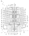
図1を参照すると、電動過給機101は、吸入した流体(たとえば気体であり、本実施の形態では空気とする)を過給するための過給部1と、過給部1を回転電機である電動モータ30を用いて駆動するための駆動部2とによって構成されている。
Embodiments of the present invention will be described below with reference to the accompanying drawings.
Embodiment 1 FIG.
First, the configuration of the
Referring to FIG. 1, an
過給部1は、回転することによって吸入空気を過給するインペラ40と、インペラ40と一体回転可能なシャフト22と、コンプレッサカバー11及びシールプレート12とを備えている。コンプレッサカバー11及びシールプレート12はたとえば金属製であり、互いに組み付けられることによって内部にインペラ40を収容する。ここで、シャフト22は回転軸を構成している。
The supercharging unit 1 includes an
シャフト22は、コンプレッサカバー11の内部からシールプレート12を貫通して駆動部2に延在している。このとき、シールプレート12はシャフト22の径方向に延在している。
コンプレッサカバー11及びシールプレート12によって囲まれた内部には、インペラ40を回転可能に収容するインペラ室15と、インペラ室15からシャフト22の軸方向に延在して外部に開口する吸入路16と、インペラ室15に連通し且つインペラ40の周囲を囲むように延在して外部に開口する環状の排出路17とが形成されている。
The
Inside the
駆動部2は、金属製の有底筒状のモータケース13と、モータケース13の開口を閉鎖するエンドプレート14及び後端部材35とを備えている。そして、モータケース13、エンドプレート14及び後端部材35は、その内部に電動モータ30を収容するモータ室18を形成している。ここで、モータ室18は、回転電機室を構成している。
The drive unit 2 includes a metal bottomed
モータケース13の筒状の側壁13aの外周側には、周囲の空気によるモータケース13の冷却効率を向上させるために複数の放熱フィン13cが一体に突出形成されている。
そして、コンプレッサカバー11、シールプレート12、モータケース13、エンドプレート14及び後端部材35は、電動過給機101のハウジング10を形成している。
On the outer peripheral side of the
The compressor cover 11, the
モータケース13の底部である底壁13bには、シールプレート12が固定されている。そして、底壁13bの中央には、モータ室18内に開口すると共にシールプレート12に向かって開口する底壁貫通穴13b1が貫通形成されている。底壁貫通穴13b1は、シャフト22の外径よりも大きい内径を有し、シャフト22を通している。そして、底壁13bは、シャフト22の径方向に延在している。ここで、底壁13bは、モータ室18とインペラ室15とを隔てる隔壁を構成し、底壁貫通穴13b1は、シャフト22の回転軸挿通穴を構成している。
A
さらに、シールプレート12には、底壁貫通穴13b1に隣接し且つ連通するプレート貫通穴12aが貫通形成されている。そして、シャフト22は、プレート貫通穴12a及び底壁貫通穴13b1を通って、モータ室18内に延在している。このとき、シャフト22の軸方向はモータケース13の筒状の側壁13aの延在方向に沿う方向となっている。
Further, the
インペラ室15とモータ室18との間には、開口28が設けられる。本実施形態では、開口28は、モータケース13の底壁13bの底壁貫通穴13b1と、シールプレート12のプレート貫通穴12aとによって構成される。開口28は、インペラ室15とモータ室18との間にシャフト22を挿通させるための空間として機能する。
An
また、開口28は、インペラ室15とモータ室18との間で空気が流通可能な流入口としても機能する。「流通可能」とは、本明細書の記載に基づき当業者が適宜定義可能であるが、たとえば、インペラ室15とモータ室18とがいずれも密閉された状態で開口28の両端に気圧差が生じた場合に、比較的短時間(たとえば1秒未満)で、両端の気圧差が無視できる程度に小さくなるような開口面積があることをいう。なお、本実施形態では、開口28には、インペラ室15とモータ室18との間を隔絶するためのいかなるシール構造も設けられない。
The
シャフト22の外周面22cは、モータ室18内に設けられた第一軸受23及び第二軸受24によって周方向に回転可能に支持されている。第一軸受23は、底壁13bの近傍でシャフト22を支持し、第二軸受24は、エンドプレート14側の端部22bの近傍でシャフト22を支持している。第一軸受23及び第二軸受24は、いずれも、外輪及び内輪を備えており、外輪及び内輪は互いに回転可能である。第一軸受23及び第二軸受24はたとえばボールベアリングである。また、本実施形態では、第一軸受23及び第二軸受24はグリス封入式のアンギュラーベアリングである。
An outer
第一軸受23は、底壁貫通穴13b1に隣接して位置している。第一軸受23は、第一軸受スリーブ25によって支持及び固定される。第一軸受スリーブ25は、第一軸受23の外周を囲むフランジ付円筒形状を有する。第一軸受スリーブ25は、底壁13bに固定される。底壁貫通穴13b1の内径は、第一軸受23の外径よりも小径であり、第一軸受23は、底壁貫通穴13b1における底壁13bとシャフト22との間の隙間を塞いでいる。
The first bearing 23 is located adjacent to the bottom wall through hole 13b1. The first bearing 23 is supported and fixed by a first bearing
第二軸受24は、第二軸受スリーブ26によって支持及び固定されている。第二軸受スリーブ26は、第二軸受24の外周を囲むフランジ付円筒形状を有する。第二軸受スリーブ26は、エンドプレート14に固定される。
The
シャフト22は、端部22a側において、インペラ40の中心の挿通孔41内に通されている。シャフト22の外周面22c上には、固定ナット27が取り付けられている。固定ナット27は、インペラ40に対して端部22a側に位置し、シャフト22に逆ねじ方式で螺合する。
The
シャフト22は、自由端を持つオーバーハング部22dを含む。オーバーハング部22dとは、シャフト22が支持されている部分より端部に近い部分をいう。図1の例では、オーバーハング部22dは、端部22aから、第一軸受23の前端23a(第一軸受23の軸方向両端のうちシャフト22の端部22aに近い側のもの)までの部分として定義される。
The
モータ室18内における第一軸受23及び第二軸受24の間において、シャフト22の外周面22c上には、円筒状のロータコア31がシャフト22と一体に回転するように設けられている。ロータコア31内には、その外周面に沿って永久磁石32が埋め込まれている。
Between the
さらに、モータ室18内では、ロータコア31の外周を囲むようにして円筒状のステータコア33が設けられている。ステータコア33は、モータケース13の側壁13aに固定されている。さらに、ステータコア33内では巻線が巻回され、この巻線はコイル34(交流巻線)を形成し、ステータコア33の両端から突出している。
Further, in the
そして、巻線に電力が供給されると、コイル34から回転磁界が発生し、この回転磁界の作用を永久磁石32が受けることによって、ロータコア31がシャフト22及びインペラ40と共に回転駆動される。
When electric power is supplied to the winding, a rotating magnetic field is generated from the
上述のようなシャフト22、ロータコア31、永久磁石32、ステータコア33及びコイル34は、電動モータ30を構成している。そして、シャフト22は、インペラ40及び電動モータ30の回転軸を兼ねている。
The
駆動部2は、開口28以外の部分において、モータ室18を外部から隔絶するシール構造を備える。本実施形態では、このシール構造は、Oリング50,51及び52を含む。Oリング50は、シールプレート12とモータケース13との間において、モータ室18を外部から隔絶し、Oリング51は、モータケース13とエンドプレート14との間において、モータ室18を外部から隔絶し、Oリング52は、エンドプレート14と後端部材35との間において、モータ室18を外部から隔絶する。なお、このシール構造は、モータケース13、エンドプレート14及び後端部材35を含むということもできる。
The drive unit 2 includes a seal structure that isolates the
次に、この発明の実施の形態1に係る電動過給機101の動作を説明する。
図1を参照すると、電動過給機101において、図示しない電源によって電動モータ30のコイル34に電力が印加されると、コイル34が発生する回転磁界によってロータコア31が回転駆動され、それによって、シャフト22及びインペラ40が中心軸CAを中心に高速回転駆動される。これに伴い、インペラ40は、吸入路16から吸入する空気を圧縮つまり過給して排出路17へと圧送する。
Next, the operation of the
Referring to FIG. 1, in the
ここで、開口28はシールされていないので、インペラ室15内で圧縮された空気は、開口28を通ってモータ室18に流入することが可能となっている。ただし、モータ室18は、開口28以外の部分において外部から隔絶されているので、モータ室18に流入した空気が開口28以外の部分からモータ室18の外部に流出することは抑制される。
Here, since the
電動過給機101の動作に伴ってシャフト22が回転すると、回転振動に伴って端部22aが振動する。シャフト22は第一軸受23及び第二軸受24によって支持されているので、端部22aの振動の振幅はオーバーハング部22dの長さに依存する。本実施形態では、開口28にシール構造を設ける必要がないので、開口28の軸方向の長さを短く設計することができ(たとえば、シールプレート12やモータケース13の底壁13bを薄くできる)、オーバーハング部22dの長さを短くできる。結果として、回転振動に伴う端部22aの振幅が縮小される。
When the
このように、実施の形態1に係る電動過給機101によれば、回転振動に伴う端部22aの振幅を縮小することができる。また、シャフト22の周りにシールカラーやシールリング等を設ける必要がないので、シャフト22を含む回転体の組み付け精度が向上するとともに、動バランスも向上する。さらに、部品点数が削減されるので、コストも低減可能である。
Thus, according to the
また、モータ室18は、開口28以外の部分において外部から隔絶されているので、圧縮された空気が外部に漏れることがない。したがって、圧縮された空気の漏れ量が低減され、コンプレッサ効率が向上する。
Further, since the
なお、従来の電動過給機では、シールカラーやシールリング等を用いてインペラ室とモータ室との間を隔絶する一方で、モータ室は外部から隔絶しない構成となっているが、このような構成では、シャフトの円滑な回転を保証するため密閉性がある程度犠牲になり、漏れ量が大きくなる。したがって、本実施形態の電動過給機101は、従来の構成と比較しても、圧縮された空気の漏れ量を低減するということができる。
In the conventional electric supercharger, the impeller chamber and the motor chamber are isolated from each other using a seal collar, a seal ring, etc., while the motor chamber is configured not to be isolated from the outside. In the configuration, the sealing performance is sacrificed to some extent to ensure smooth rotation of the shaft, and the amount of leakage increases. Therefore, it can be said that the
また、モータ室18を、少なくとも開口28以外の部分において外部から隔絶するという構成は、たとえば外部からモータ室18への潤滑剤(オイル等)の供給が困難となる可能性があるため、当業者が容易に想到し得ないものである。この点について、本実施形態では、第一軸受23及び第二軸受24をグリス封入式の軸受とすることにより、潤滑剤の供給を不要とし、潤滑剤の供給に関する問題を解決している。ただし、モータ室18をシールしつつ軸受の潤滑が十分に維持できる場合等には、グリス封入式でない軸受を用いる構成としてもよい。
Further, the configuration in which the
本実施形態では、開口28には、インペラ室15とモータ室18との間を隔絶するためのいかなるシール構造も設けられない。変形例として、開口28において、空気の流通を抑制すること以外の目的のためのシール構造を設けてもよい。また、インペラ室15とモータ室18との間において、空気の流通が可能な程度に維持されるものであれば、空気の流通をある程度抑制する構造等を設けてもよい。
In the present embodiment, the
実施の形態2.
実施の形態2は、実施の形態1の電動過給機101を備える過給システムに係るものである。
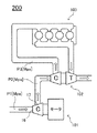
図2に、実施の形態2に係る過給システム200の構成概略を示す。過給システム200は、いわゆる2ステージターボの構成を有し、吸気を2段階で圧縮し過給する。
Embodiment 2. FIG.
The second embodiment relates to a supercharging system including the
FIG. 2 shows a schematic configuration of a
過給システム200は、内燃機関103の吸気を過給する。このために、過給システム200は、実施の形態1に係る電動過給機(第一過給機)101と、第二過給機102とを備える。第一過給機101は低圧側の過給機であり、所定の第一圧力P1(たとえば大気圧)の空気を、第一圧力P1より高い所定の第二圧力P2に圧縮して第二過給機102に供給する。
The supercharging
なお、図2は概略を示すものであり、インタークーラーや、逆止弁を含む切り替え構造等については省略しているが、これらを適宜設けてもよい。 Note that FIG. 2 shows an outline, and an intercooler, a switching structure including a check valve, and the like are omitted, but these may be provided as appropriate.
第二過給機102は高圧側の過給機であり、本実施形態では内燃機関103の排気圧を利用して吸気を過給する。第二過給機102は、第一過給機101の下流に設けられ、第一過給機101から供給される第二圧力P2の空気を、第二圧力P2より高い所定の第三圧力P3に圧縮して内燃機関103に供給する。
The
ここで図1を参照すると、第一過給機101では動作に伴って内部に熱が発生し、モータ室18内の温度が上昇する。一方で、開口28を介して、吐出圧(第二圧力P2)の圧縮空気がモータ室18に流入するので、モータ室18の室内温度は圧縮空気の温度に応じて変動する。したがって、圧縮空気の温度が所定の閾値温度未満となるように、第一過給機101の過給率を設定しておけば、モータ室18内の温度がこの閾値温度以上となった場合には、圧縮空気によってモータ室18内を冷却することができる。
Referring now to FIG. 1, heat is generated inside the
たとえば、第二圧力P2の圧縮空気の温度が70℃またはこれ未満となるように第一過給機101を設計することができ、この場合にはモータ室18内において有意の冷却効果を得ることができる。とくに、図1に示すように第一軸受23はモータ室18内において開口28に近い位置に配置されるので、第一軸受23に対して大きな冷却効果を得ることができる。
For example, the
なお、上述のように第一過給機101の下流には第二過給機102が設けられるので、第二圧力P2が比較的低い圧力であっても、内燃機関103に対しては十分に過給された第三圧力P3の圧縮空気を供給することが可能である。
Since the
このように、実施の形態2に係る過給システム200によれば、第一過給機101において、開口28を介して第一軸受23を効率的に冷却することができる。また、実施の形態1と同様に、第一過給機101において、回転振動に伴う端部22aの振幅を縮小することができる。
Thus, according to the
なお、図2では第二過給機102は電動過給機ではないが、冷却が適切に行える場合には、第二過給機102も第一過給機101のような電動過給機としてもよい。また、冷却が適切に行える場合において、第二過給機すなわち高圧側の過給機が電動過給機である場合には、第一過給機すなわち低圧側の過給機を電動式以外のもの(たとえば実施の形態2の第二過給機102のように排気圧を利用するもの)としてもよい。
In FIG. 2, the
15 インペラ室、18 モータ室、22 シャフト(回転軸)、23 第一軸受(軸受)、24 第二軸受(軸受)、28 開口、30 電動モータ(モータ)、40 インペラ、50,51,52 Oリング(シール構造)、101 電動過給機(第一過給機)、102 第二過給機、200 過給システム。 15 impeller chamber, 18 motor chamber, 22 shaft (rotating shaft), 23 first bearing (bearing), 24 second bearing (bearing), 28 opening, 30 electric motor (motor), 40 impeller, 50, 51, 52 O Ring (seal structure), 101 Electric supercharger (first supercharger), 102 Second supercharger, 200 Supercharging system.
Claims (5)
前記インペラを収容するインペラ室と、
前記インペラを回転駆動するモータと、
前記モータを収容するモータ室と、
前記インペラおよび前記モータに共通の回転軸と、
前記インペラ室から前記モータ室まで延在する前記回転軸が挿通されるとともに前記インペラ室と前記モータ室とを連通して前記インペラ室と前記モータ室との間で前記流体を流通可能とする開口と、
前記モータ室内の前記流体が前記開口以外から前記モータ室の外部に漏れることがないように、前記開口以外の部分において、前記モータ室を外部から隔絶するシール構造と、
前記モータ室内に配置され、前記回転軸を回転可能に支持するグリス封入式の軸受と、
を備える、電動過給機。 An impeller that supercharges fluid by rotating;
An impeller chamber for accommodating the impeller;
A motor for rotationally driving the impeller;
A motor chamber that houses the motor;
A rotating shaft common to the impeller and the motor;
Openings to allow flow of said fluid between said rotary shaft is the motor chamber and the impeller chamber communicating with said motor chamber and said impeller chamber while being inserted extending from said impeller chamber to the motor chamber When,
A seal structure that isolates the motor chamber from the outside in a portion other than the opening so that the fluid in the motor chamber does not leak outside the motor chamber from outside the opening ;
A grease-filled bearing disposed in the motor chamber and rotatably supporting the rotating shaft;
An electric supercharger.
前記電動過給機はモータケースを有し、前記モータケースは前記シールプレートに固定され、前記モータケースは内部に前記モータを収容し、 The electric supercharger has a motor case, the motor case is fixed to the seal plate, the motor case accommodates the motor therein,
前記開口は、前記シールプレートに形成されたプレート貫通穴と、前記プレート貫通穴に隣接しかつ前記プレート貫通穴に連通するように前記モータケースに形成されたモータケース貫通穴とを有し、 The opening has a plate through hole formed in the seal plate, and a motor case through hole formed in the motor case so as to be adjacent to the plate through hole and communicate with the plate through hole,
前記シール構造は、前記開口の周囲において前記シールプレートと前記モータケースとの間をシールする第一シール部材を有する、 The seal structure includes a first seal member that seals between the seal plate and the motor case around the opening.
請求項1に記載の電動過給機。The electric supercharger according to claim 1.
前記シール構造は、前記モータケースと前記後端閉鎖構造との間をシールする第二シール部材を備える、 The seal structure includes a second seal member that seals between the motor case and the rear end closing structure.
請求項1または2に記載の電動過給機。The electric supercharger according to claim 1 or 2.
前記第二シール部材は、前記モータケースと前記エンドプレートとの間をシールし、 The second seal member seals between the motor case and the end plate;
前記シール構造は、前記エンドプレートと前記後端部材との間をシールする第三シール部材を備える、 The seal structure includes a third seal member that seals between the end plate and the rear end member.
請求項3に記載の電動過給機。The electric supercharger according to claim 3.
前記第一軸受はモータケースに固定された軸受スリーブに保持されており、 The first bearing is held by a bearing sleeve fixed to the motor case,
前記モータケース貫通穴の内径は前記第一軸受の外径よりも小径である、 The inner diameter of the motor case through hole is smaller than the outer diameter of the first bearing.
請求項2〜4のいずれか一項に記載の電動過給機。The electric supercharger as described in any one of Claims 2-4.
Priority Applications (4)
| Application Number | Priority Date | Filing Date | Title |
|---|---|---|---|
| JP2014075360A JP6156232B2 (en) | 2014-04-01 | 2014-04-01 | Electric turbocharger |
| PCT/JP2015/058255 WO2015151835A1 (en) | 2014-04-01 | 2015-03-19 | Electrically driven supercharger, and supercharging system |
| US15/129,018 US11143192B2 (en) | 2014-04-01 | 2015-03-19 | Electric supercharger and supercharging system |
| EP15774295.8A EP3128150B1 (en) | 2014-04-01 | 2015-03-19 | Electrically driven supercharger, and supercharging system |
Applications Claiming Priority (1)
| Application Number | Priority Date | Filing Date | Title |
|---|---|---|---|
| JP2014075360A JP6156232B2 (en) | 2014-04-01 | 2014-04-01 | Electric turbocharger |
Publications (3)
| Publication Number | Publication Date |
|---|---|
| JP2015197064A JP2015197064A (en) | 2015-11-09 |
| JP2015197064A5 JP2015197064A5 (en) | 2016-08-18 |
| JP6156232B2 true JP6156232B2 (en) | 2017-07-05 |
Family
ID=54240166
Family Applications (1)
| Application Number | Title | Priority Date | Filing Date |
|---|---|---|---|
| JP2014075360A Expired - Fee Related JP6156232B2 (en) | 2014-04-01 | 2014-04-01 | Electric turbocharger |
Country Status (4)
| Country | Link |
|---|---|
| US (1) | US11143192B2 (en) |
| EP (1) | EP3128150B1 (en) |
| JP (1) | JP6156232B2 (en) |
| WO (1) | WO2015151835A1 (en) |
Families Citing this family (2)
| Publication number | Priority date | Publication date | Assignee | Title |
|---|---|---|---|---|
| KR101918640B1 (en) * | 2018-04-20 | 2018-11-14 | 최창묵 | Blower |
| US10746099B1 (en) * | 2019-04-03 | 2020-08-18 | GM Global Technology Operations LLC | Multi-step bore turbocharger |
Family Cites Families (18)
| Publication number | Priority date | Publication date | Assignee | Title |
|---|---|---|---|---|
| JPH0315696A (en) * | 1989-06-13 | 1991-01-24 | Nikkiso Co Ltd | Enclosed compressor |
| DE3943113A1 (en) * | 1989-12-27 | 1991-07-04 | Leybold Ag | FAN OR PUMP WITH VERTICALLY ARRANGED SHAFT |
| US5425345A (en) * | 1994-10-31 | 1995-06-20 | Chrysler Corporation | Mechanically driven centrifugal air compressor with hydrodynamic thrust load transfer |
| US6102672A (en) | 1997-09-10 | 2000-08-15 | Turbodyne Systems, Inc. | Motor-driven centrifugal air compressor with internal cooling airflow |
| US6192871B1 (en) * | 1998-10-30 | 2001-02-27 | Vortech Engineering, Inc. | Compact supercharger |
| US7384198B2 (en) * | 2000-08-09 | 2008-06-10 | Nsk Ltd. | Rolling bearing |
| US6449950B1 (en) * | 2000-09-12 | 2002-09-17 | Honeywell International Inc. | Rotor and bearing system for electrically assisted turbocharger |
| JP3952974B2 (en) * | 2003-03-17 | 2007-08-01 | トヨタ自動車株式会社 | Control device for internal combustion engine |
| WO2004111458A1 (en) * | 2003-06-17 | 2004-12-23 | Matsushita Electric Industrial Co., Ltd. | Air-feeding device |
| JP2005036664A (en) * | 2003-07-16 | 2005-02-10 | Mitsubishi Heavy Ind Ltd | Compressor, turbo-charger, and fuel cell |
| JP4539487B2 (en) * | 2005-08-05 | 2010-09-08 | 株式会社Ihi | Supercharger with electric motor |
| JP4692820B2 (en) * | 2005-08-11 | 2011-06-01 | 株式会社Ihi | Supercharger with electric motor |
| JP5293941B2 (en) | 2008-06-11 | 2013-09-18 | 株式会社Ihi | Regeneration method of dust collection filter |
| DE102008061113A1 (en) | 2008-12-09 | 2010-06-10 | Bosch Mahle Turbo Systems Gmbh & Co. Kg | Exhaust gas turbocharger for internal-combustion engine, particularly of motor vehicle, has shaft, which is mounted in housing of exhaust gas turbocharger by antifriction bearing in pivoted manner |
| US8616831B2 (en) * | 2009-08-11 | 2013-12-31 | GM Global Technology Operations LLC | Simplified housing for a fuel cell compressor |
| JP5533318B2 (en) | 2010-06-17 | 2014-06-25 | 株式会社Ihi | Turbo machine |
| JP5535992B2 (en) * | 2011-07-15 | 2014-07-02 | 三菱重工業株式会社 | Electric supercharged compressor, its assembly method and internal combustion engine |
| JP5931562B2 (en) | 2012-04-25 | 2016-06-08 | 三菱電機株式会社 | Electric turbocharger |
-
2014
- 2014-04-01 JP JP2014075360A patent/JP6156232B2/en not_active Expired - Fee Related
-
2015
- 2015-03-19 EP EP15774295.8A patent/EP3128150B1/en not_active Not-in-force
- 2015-03-19 WO PCT/JP2015/058255 patent/WO2015151835A1/en not_active Ceased
- 2015-03-19 US US15/129,018 patent/US11143192B2/en not_active Expired - Fee Related
Also Published As
| Publication number | Publication date |
|---|---|
| WO2015151835A1 (en) | 2015-10-08 |
| US20170101995A1 (en) | 2017-04-13 |
| EP3128150A1 (en) | 2017-02-08 |
| EP3128150B1 (en) | 2020-12-23 |
| US11143192B2 (en) | 2021-10-12 |
| JP2015197064A (en) | 2015-11-09 |
| EP3128150A4 (en) | 2017-04-19 |
Similar Documents
| Publication | Publication Date | Title |
|---|---|---|
| US8294319B2 (en) | Motor rotor and method for correcting rotating balance thereof | |
| CN104040145B (en) | Electrically Assisted Turbocharger | |
| US7530230B2 (en) | Supercharger with electric motor | |
| CN103597185B (en) | Electric supercharging device and multistage supercharging system | |
| CN101688469B (en) | Supercharger with electric motor | |
| US8096126B2 (en) | Motor-driven supercharger | |
| US8616831B2 (en) | Simplified housing for a fuel cell compressor | |
| JP2009097519A (en) | Motor-driven centrifugal compressor having inside cooling air | |
| JP2019190457A (en) | Fluid compressor | |
| WO2013176028A1 (en) | Vacuum pump | |
| CN105829733B (en) | Multistage Electric Centrifugal Compressor | |
| CN107532505B (en) | rotating machinery | |
| JP6156232B2 (en) | Electric turbocharger | |
| CN107269546A (en) | Electronic water pump | |
| US10781823B2 (en) | Impeller and supercharger | |
| WO2015107840A1 (en) | Electric supercharger | |
| WO2020196117A1 (en) | Electric compressor | |
| CN116635616A (en) | Motor rotor and supercharger | |
| KR101289800B1 (en) | Permanent magnetic motor and fluid charger comprising the same | |
| WO2020137649A1 (en) | Pump | |
| JP2017099147A (en) | Motor and electric supercharger provided with the same | |
| KR200414049Y1 (en) | Air tight mini pump | |
| JP2015194106A (en) | electric supercharger | |
| CN116490681A (en) | electric supercharger | |
| TH45743B (en) | Motorized supercharger |
Legal Events
| Date | Code | Title | Description |
|---|---|---|---|
| A521 | Request for written amendment filed |
Free format text: JAPANESE INTERMEDIATE CODE: A523 Effective date: 20160629 |
|
| A621 | Written request for application examination |
Free format text: JAPANESE INTERMEDIATE CODE: A621 Effective date: 20160629 |
|
| TRDD | Decision of grant or rejection written | ||
| A01 | Written decision to grant a patent or to grant a registration (utility model) |
Free format text: JAPANESE INTERMEDIATE CODE: A01 Effective date: 20170509 |
|
| A61 | First payment of annual fees (during grant procedure) |
Free format text: JAPANESE INTERMEDIATE CODE: A61 Effective date: 20170522 |
|
| R151 | Written notification of patent or utility model registration |
Ref document number: 6156232 Country of ref document: JP Free format text: JAPANESE INTERMEDIATE CODE: R151 |
|
| LAPS | Cancellation because of no payment of annual fees |