EP3128150B1 - Electrically driven supercharger, and supercharging system - Google Patents
Electrically driven supercharger, and supercharging system Download PDFInfo
- Publication number
- EP3128150B1 EP3128150B1 EP15774295.8A EP15774295A EP3128150B1 EP 3128150 B1 EP3128150 B1 EP 3128150B1 EP 15774295 A EP15774295 A EP 15774295A EP 3128150 B1 EP3128150 B1 EP 3128150B1
- Authority
- EP
- European Patent Office
- Prior art keywords
- motor
- chamber
- supercharger
- impeller
- opening
- Prior art date
- Legal status (The legal status is an assumption and is not a legal conclusion. Google has not performed a legal analysis and makes no representation as to the accuracy of the status listed.)
- Active
Links
- 239000012530 fluid Substances 0.000 claims description 8
- 239000004519 grease Substances 0.000 claims description 5
- 238000010276 construction Methods 0.000 description 14
- 238000001816 cooling Methods 0.000 description 5
- 238000007599 discharging Methods 0.000 description 5
- 238000002485 combustion reaction Methods 0.000 description 4
- 230000002093 peripheral effect Effects 0.000 description 4
- 238000004804 winding Methods 0.000 description 4
- 230000000694 effects Effects 0.000 description 3
- 239000000314 lubricant Substances 0.000 description 3
- 239000002184 metal Substances 0.000 description 2
- 230000004323 axial length Effects 0.000 description 1
- 238000005461 lubrication Methods 0.000 description 1
- 238000005192 partition Methods 0.000 description 1
- 230000005855 radiation Effects 0.000 description 1
- 238000011144 upstream manufacturing Methods 0.000 description 1
Images

Classifications
-
- F—MECHANICAL ENGINEERING; LIGHTING; HEATING; WEAPONS; BLASTING
- F04—POSITIVE - DISPLACEMENT MACHINES FOR LIQUIDS; PUMPS FOR LIQUIDS OR ELASTIC FLUIDS
- F04D—NON-POSITIVE-DISPLACEMENT PUMPS
- F04D25/00—Pumping installations or systems
- F04D25/02—Units comprising pumps and their driving means
- F04D25/06—Units comprising pumps and their driving means the pump being electrically driven
- F04D25/0606—Units comprising pumps and their driving means the pump being electrically driven the electric motor being specially adapted for integration in the pump
-
- F—MECHANICAL ENGINEERING; LIGHTING; HEATING; WEAPONS; BLASTING
- F02—COMBUSTION ENGINES; HOT-GAS OR COMBUSTION-PRODUCT ENGINE PLANTS
- F02B—INTERNAL-COMBUSTION PISTON ENGINES; COMBUSTION ENGINES IN GENERAL
- F02B37/00—Engines characterised by provision of pumps driven at least for part of the time by exhaust
- F02B37/04—Engines with exhaust drive and other drive of pumps, e.g. with exhaust-driven pump and mechanically-driven second pump
-
- F—MECHANICAL ENGINEERING; LIGHTING; HEATING; WEAPONS; BLASTING
- F02—COMBUSTION ENGINES; HOT-GAS OR COMBUSTION-PRODUCT ENGINE PLANTS
- F02B—INTERNAL-COMBUSTION PISTON ENGINES; COMBUSTION ENGINES IN GENERAL
- F02B39/00—Component parts, details, or accessories relating to, driven charging or scavenging pumps, not provided for in groups F02B33/00 - F02B37/00
- F02B39/02—Drives of pumps; Varying pump drive gear ratio
- F02B39/08—Non-mechanical drives, e.g. fluid drives having variable gear ratio
- F02B39/10—Non-mechanical drives, e.g. fluid drives having variable gear ratio electric
-
- F—MECHANICAL ENGINEERING; LIGHTING; HEATING; WEAPONS; BLASTING
- F04—POSITIVE - DISPLACEMENT MACHINES FOR LIQUIDS; PUMPS FOR LIQUIDS OR ELASTIC FLUIDS
- F04D—NON-POSITIVE-DISPLACEMENT PUMPS
- F04D25/00—Pumping installations or systems
- F04D25/02—Units comprising pumps and their driving means
- F04D25/08—Units comprising pumps and their driving means the working fluid being air, e.g. for ventilation
-
- F—MECHANICAL ENGINEERING; LIGHTING; HEATING; WEAPONS; BLASTING
- F04—POSITIVE - DISPLACEMENT MACHINES FOR LIQUIDS; PUMPS FOR LIQUIDS OR ELASTIC FLUIDS
- F04D—NON-POSITIVE-DISPLACEMENT PUMPS
- F04D25/00—Pumping installations or systems
- F04D25/16—Combinations of two or more pumps ; Producing two or more separate gas flows
-
- F—MECHANICAL ENGINEERING; LIGHTING; HEATING; WEAPONS; BLASTING
- F04—POSITIVE - DISPLACEMENT MACHINES FOR LIQUIDS; PUMPS FOR LIQUIDS OR ELASTIC FLUIDS
- F04D—NON-POSITIVE-DISPLACEMENT PUMPS
- F04D29/00—Details, component parts, or accessories
- F04D29/05—Shafts or bearings, or assemblies thereof, specially adapted for elastic fluid pumps
- F04D29/053—Shafts
-
- F—MECHANICAL ENGINEERING; LIGHTING; HEATING; WEAPONS; BLASTING
- F04—POSITIVE - DISPLACEMENT MACHINES FOR LIQUIDS; PUMPS FOR LIQUIDS OR ELASTIC FLUIDS
- F04D—NON-POSITIVE-DISPLACEMENT PUMPS
- F04D29/00—Details, component parts, or accessories
- F04D29/05—Shafts or bearings, or assemblies thereof, specially adapted for elastic fluid pumps
- F04D29/056—Bearings
- F04D29/059—Roller bearings
-
- F—MECHANICAL ENGINEERING; LIGHTING; HEATING; WEAPONS; BLASTING
- F04—POSITIVE - DISPLACEMENT MACHINES FOR LIQUIDS; PUMPS FOR LIQUIDS OR ELASTIC FLUIDS
- F04D—NON-POSITIVE-DISPLACEMENT PUMPS
- F04D29/00—Details, component parts, or accessories
- F04D29/08—Sealings
- F04D29/083—Sealings especially adapted for elastic fluid pumps
-
- F—MECHANICAL ENGINEERING; LIGHTING; HEATING; WEAPONS; BLASTING
- F04—POSITIVE - DISPLACEMENT MACHINES FOR LIQUIDS; PUMPS FOR LIQUIDS OR ELASTIC FLUIDS
- F04D—NON-POSITIVE-DISPLACEMENT PUMPS
- F04D29/00—Details, component parts, or accessories
- F04D29/08—Sealings
- F04D29/10—Shaft sealings
- F04D29/102—Shaft sealings especially adapted for elastic fluid pumps
-
- F—MECHANICAL ENGINEERING; LIGHTING; HEATING; WEAPONS; BLASTING
- F04—POSITIVE - DISPLACEMENT MACHINES FOR LIQUIDS; PUMPS FOR LIQUIDS OR ELASTIC FLUIDS
- F04D—NON-POSITIVE-DISPLACEMENT PUMPS
- F04D29/00—Details, component parts, or accessories
- F04D29/40—Casings; Connections of working fluid
- F04D29/42—Casings; Connections of working fluid for radial or helico-centrifugal pumps
- F04D29/4206—Casings; Connections of working fluid for radial or helico-centrifugal pumps especially adapted for elastic fluid pumps
-
- F—MECHANICAL ENGINEERING; LIGHTING; HEATING; WEAPONS; BLASTING
- F04—POSITIVE - DISPLACEMENT MACHINES FOR LIQUIDS; PUMPS FOR LIQUIDS OR ELASTIC FLUIDS
- F04D—NON-POSITIVE-DISPLACEMENT PUMPS
- F04D29/00—Details, component parts, or accessories
- F04D29/66—Combating cavitation, whirls, noise, vibration or the like; Balancing
- F04D29/661—Combating cavitation, whirls, noise, vibration or the like; Balancing especially adapted for elastic fluid pumps
- F04D29/668—Combating cavitation, whirls, noise, vibration or the like; Balancing especially adapted for elastic fluid pumps damping or preventing mechanical vibrations
-
- Y—GENERAL TAGGING OF NEW TECHNOLOGICAL DEVELOPMENTS; GENERAL TAGGING OF CROSS-SECTIONAL TECHNOLOGIES SPANNING OVER SEVERAL SECTIONS OF THE IPC; TECHNICAL SUBJECTS COVERED BY FORMER USPC CROSS-REFERENCE ART COLLECTIONS [XRACs] AND DIGESTS
- Y02—TECHNOLOGIES OR APPLICATIONS FOR MITIGATION OR ADAPTATION AGAINST CLIMATE CHANGE
- Y02T—CLIMATE CHANGE MITIGATION TECHNOLOGIES RELATED TO TRANSPORTATION
- Y02T10/00—Road transport of goods or passengers
- Y02T10/10—Internal combustion engine [ICE] based vehicles
- Y02T10/12—Improving ICE efficiencies
Definitions
- the present invention relates to an electric supercharger and a supercharging system.
- Patent Document 1 Japanese Patent Application Laid Open No. 2013-227889
- WO 2013/011839 A1 discloses an electrical supercharger according to the preamble of appended claim 1.
- the present invention is made in order to solve this problem and is aimed at providing an electric supercharger and a supercharging system that can reduce the amplitude of vibration in the end of the shaft due to rotational vibration.
- an electric supercharger related to the present invention comprises:
- a supercharging system related to the present invention comprises:
- a seal structure which does not allow fluid to pass between the impeller chamber and the motor chamber is unnecessary, so the overhanging portion of the shaft can be shorter, thereby reducing the amplitude of the vibrations in the end of the shaft.
- the electric supercharger 101 is constituted by a supercharging portion 1 for supercharging intake fluid (gas for example and air in the present embodiment) and a driving portion 2 for driving the supercharging portion 1 by using an electric motor 30 which is a rotating electric machine.
- the supercharging portion 1 comprises an impeller 40 for supercharging intake air by rotation, a shaft 22 integrally rotatable with the impeller 40, a compressor cover 11 and a seal plate 12.
- the compressor cover 11 and the seal plate 12 are for example made of a metal and assembled together to accommodate the impeller 40 inside.
- the shaft 22 constitutes a rotating shaft.
- the shaft extends from inside the compressor cover 11 to the driving portion 2 through the seal plate 12.
- the seal plate 12 extends in a radial direction of the shaft 22.
- an impeller chamber 15, an intake path 16 and an annular discharging path 17 are formed in an interior surrounded by the compressor cover 11 and the seal plate 12.
- the impeller chamber 15 accommodates the impeller 40 to be rotatable.
- the intake path 16 extends from the impeller chamber 15 in an axial direction of the shaft 22 and opens externally.
- the discharging path 17 is connected to the impeller chamber 15, extends to surround a periphery of the impeller 40 and opens externally.
- the driving portion 2 comprises a motor case 13, an end plate 14 and a rear end member 35.
- the motor case 13 is made of a metal in a cylindrical shape having a bottom.
- the end plate 14 and the rear end member 35 close an opening of the motor case 13.
- the motor case 13, the end plate 14 and the rear end member 35 form a motor chamber 18 accommodating the electrical motor 30 inside.
- the motor chamber 18 constitutes a rotating electric machine chamber.
- a plurality of radiation fins 13c are formed integrally therewith and protruding therefrom in order to enhance cooling efficiency of the motor case 13 by circumambient air.
- the compressor cover 11, the seal plate 12, the motor case 13, the end plate 14 and the rear end member 35 form a housing 10 of the electric supercharger 101.
- the seal plate 12 is fixed to a bottom wall 13b which is a bottom portion of the motor case 13. Also, at the center of the bottom wall 13b, a bottom wall through hole 13b1 is formed therethrough which opens within the motor chamber 18 and opens toward the seal plate 12.
- the bottom wall through hole 13b1 has an inner diameter greater than an outer diameter of the shaft 22 so that the shaft 22 passes therethrough. Also, the bottom wall 13b extends in a radial direction of the shaft 22.
- the bottom wall 13b constitutes a partition wall separating the motor chamber 18 and the impeller chamber 15 and the bottom wall through hole 13b1 constitutes a rotating shaft passing hole for the shaft 22.
- a plate through hole 12a is formed through the seal plate 12.
- the plate through hole 12a is adjacent to the bottom wall through hole 13b1 and connected thereto.
- the shaft 22 extends through the plate through hole 12a and the bottom wall through hole 13b1 into the motor chamber 18. In this state, the axial direction of the shaft 22 is along the direction that the cylindrical side wall 13a of the motor case 13 extends.
- An opening 28 is provided between the impeller chamber 15 and the motor chamber 18.
- the opening 28 is constituted by the bottom wall through hole 13b1 at the bottom wall 13b of the motor case 13 and the plate through hole 12a of the seal plate 12.
- the opening 28 functions as space for the shaft 22 to pass between the impeller chamber 15 and the motor chamber 18.
- the opening 28 also functions as an inlet where air is able to pass therethrough between the impeller chamber 15 and the motor chamber 18.
- able to pass means for example: that there is such an opening cross sectional area that if there arises any air pressure difference between the opposite ends of the opening 28 in a state wherein both the impeller chamber 15 and the motor chamber 18 are closed, the air pressure difference between the opposite ends becomes negligible within a comparatively short period (for example less than 1 second, but this may be less than 0.5 second, less than 1.5 seconds, less than 2 seconds, etc.).
- the opening 28 is not provided with any seal structure for separating the impeller chamber 15 from the motor chamber 18.
- a peripheral surface 22c of the shaft 22 is supported by a first bearing 23 and a second bearing 24, provided within the motor chamber 18, to be rotatable in a circumferential direction.
- the first bearing 23 supports the shaft 22 in the vicinity of the bottom wall 13b and the second bearing 24 supports the shaft 22 in the vicinity of an end 22b at a side of the end plate 14.
- the first and second bearings 23 and 24 both comprise a respective outer ring and inner ring, which are rotatable with respect to each other.
- the first and second bearings 23 and 24 are for example ball bearings .
- the first and second bearings 23 and 24 are grease sealed type angular bearings.
- the first bearing 23 is located adjacent to the bottom wall through hole 13b1.
- the first bearing 23 is supported and fixed by a first bearing sleeve 25.
- the first bearing sleeve 25 has a flanged cylindrical shape surrounding a periphery of the first bearing 23.
- the first bearing sleeve 25 is fixed to the bottom wall 13b.
- An inner diameter of the bottom wall through hole 13b1 is less than an outer diameter of the first bearing 23.
- the first bearing 23 closes the gap between the bottom wall 13b and the shaft 22 by being located at the bottom wall through hole 13b1 in the opening end at the side of the motor chamber 18.
- the second bearing 24 is supported and fixed by a second bearing sleeve 26.
- the second bearing sleeve 26 has a flanged cylindrical shape surrounding a periphery of the second bearing 24.
- the second bearing sleeve 26 is fixed to the end plate 14.
- the shaft 22 passes inside a through hole 41 at the center of the impeller 40 at the side of an end 22a.
- a fixing nut 27 is attached to the shaft 22 on the peripheral surface 22c.
- the fixing nut 27 is positioned at the side of the end 22a with respect to the impeller 40 and screwed together onto the shaft 22 in a left-handed-screw manner.
- the shaft 22 includes an overhanging portion 22d having a free end.
- the overhanging portion 22d means a portion of the shaft 22 which is closer to an end with respect to the portion wherein the shaft 22 is supported.
- the overhanging portion 22d is defined to be a portion from the end 22a to a front end 23a of the first bearing 23 (i.e. an axial end of the first bearing 23 closer to the end 22a of the shaft 22).
- a cylindrical rotor core 31 is provided on the peripheral surface 22c of the shaft 22 so that rotor core 31 rotates integrally with the shaft 22.
- Permanent magnets 32 are embedded within the rotor core 31 along the peripheral surface thereof.
- a cylindrical stator core 33 is provided so that the stator core 33 surrounds the periphery of the rotor core 31.
- the stator core 33 is fixed to the side wall 13a of the motor case 13. Further, a winding is wound in the stator core 33.
- the winding forms a coil 34 (a line winding) and protrudes at the opposite ends of the stator core 33.
- the coil 34 If power is supplied to the winding, the coil 34 generates a rotating magnetic field.
- the permanent magnets 32 receive working of the rotating magnetic field and the rotor 31 is thereby driven to rotate together with the shaft 22 and the impeller 40.
- the shaft 22, the rotor core 31, the permanent magnets 32, the stator core 33 and the coil 34 described above constitute the electric motor 30. Also, the shaft 22 serves as a rotational shaft which is common between the impeller 40 and the electric motor 30.
- the driving portion 2 comprises a seal structure for separating the motor chamber 18 from the exterior at portions other than the opening 28.
- the seal structure includes O-rings 50, 51 and 52.
- the O-ring 50 separates the motor chamber 18 from the exterior between the seal plate 12 and the motor case 13.
- the O-ring 51 separates the motor chamber 18 from the exterior between the motor case 13 and the end plate 14.
- the O-ring 52 separates the motor chamber 18 from the exterior between the end plate 14 and the rear end member 35. It can be said that the seal structure also includes the seal plate 12, the motor case 13, the end plate 14 and the rear end member 35.
- the rotor core 31 is driven to rotate by the rotating magnetic field generated by the coil 34, thereby driving the shaft 22 and the impeller 40 to rotate at a high speed around a central axis CA.
- the impeller 40 compresses, i.e. supercharges, air sucked from the intake path 16 and pumps it to the discharging path 17.
- the opening 28 is not sealed, so the air compressed within the impeller chamber 15 can flow into the motor chamber 18 through the opening 28.
- the motor chamber 18 is separated from the exterior at portions other than the opening 28, so it is suppressed that the air flown into the motor chamber 18 flows out thereof at portions other than the opening 28.
- the end 22a vibrates due to rotational vibration. Because the shaft 22 is supported by the first and second bearings 23 and 24, the amplitude of the vibration of the end 22a depends on the length of the overhanging portion 22d. In the present embodiment, there is no need to provide any seal structure in the opening 28, so the axial length of the opening 28 can be designed to be short (for example, the seal plate 12 or the bottom wall 13b of the motor case 13 can be thin), and the length of the overhanging portion 22d can be short. As a result, the amplitude of the vibration of the end 22a due to the rotational vibration can be reduced.
- the amplitude of the vibration of the end 22a due to the rotational vibration can be reduced. Also, because there is no need to provide any seal collar, seal ring, etc. around the shaft 22, both assembly precision of the rotating body including the shaft 22 and the dynamic balance are improved. Further, cost can be reduced because the number of parts is reduced.
- the motor chamber 18 is separated from the exterior at portions other than the opening 28, so the compressed air does not leak out. Accordingly, the amount of compressed air leaking is reduced and compressor efficiency is improved.
- the present embodiment solves the problem related to supplying the lubricant by making the supply of lubricant unnecessary because the first and second bearings 23 and 24 are grease sealed type bearings.
- non-grease sealed type bearings (which is not according to the invention) may be used in the construction if, for example, the motor chamber 18 can be sealed while lubrication of the bearing can be maintained sufficiently.
- the opening 28 is not provided with any seal structure for separating the impeller chamber 15 from the motor chamber 18.
- a seal structure may be provided for purposes other than to suppress air flow in the opening 28.
- a structure or the like for suppressing the air flow to a certain degree may be provided between the impeller chamber 15 and the motor chamber 18 if it is possible to maintain a certain degree of air flow.
- the construction of the opening 28 may be changed.
- the opening 28 is constituted by the bottom wall through hole 13b1 in the bottom wall 13b of the motor case 13 and the plate through hole 12a of the seal plate 12.
- an additional component can be provided.
- an inner surface of the bottom wall through hole 13b1 and an inner surface of the plate through hole 12a constitute respective cylindrical surfaces.
- they may include a surface in a non-cylindrical shape.
- one or both of them may have a shape in which a cross section perpendicular to the axis is non-circular, or have varying cross sectional shapes in response to positions in an axial direction (e.g. a tapered surface).
- the diameter of the bottom wall through hole 13b1 is greater than the diameter of the plate through hole 12a.
- the diameter of the bottom wall through hole 13b1 may be less than the diameter of the plate through hole 12a or they may be equal to each other.
- a second embodiment is related to a supercharging system comprising the electric supercharger 101 related to the first embodiment.
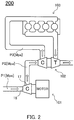
- Fig. 2 shows a schematic construction of the supercharging system 200 related to the second embodiment.
- the supercharging system 200 has a construction typically referred to as "two-stage turbocharging" and compresses and supercharges the intake air in two stages.
- the supercharging system 200 supercharges the intake air of an internal combustion engine 103.
- the supercharging system 200 comprises an electric supercharger (a first supercharger) 101 related to the first embodiment and a second supercharger 102.
- the first supercharger 101 is a supercharger in a lower pressure side.
- the first supercharger 101 compresses air of a predetermined first pressure P1 (e.g. atmospheric pressure) to a predetermined second pressure P2 higher than the first pressure P1 and supplies this to the second supercharger 102.
- a predetermined first pressure P1 e.g. atmospheric pressure
- Fig. 2 merely shows a schematic construction. Although an intercooler, a switching structure including a check valve, etc. is omitted therein, they may be provided as needed.
- the second supercharger 102 is a supercharger in a higher pressure side.
- the second supercharger 102 supercharges the intake air by utilizing a discharge pressure of the internal combustion engine 103.
- the second supercharger 102 is provided in the downstream of the first supercharger 101.
- the second supercharger 102 compresses the air of the second pressure P2 supplied by the first supercharger 101 to a predetermined third pressure P3 higher than the second pressure P2 and supplies this to the internal combustion engine 103.
- the first supercharger 101 generates heat inside as it operates and the temperature within the motor chamber 18 rises.
- the compressed air of the discharging pressure (the second pressure P2) flows into the motor chamber 18 through the opening 28, so the chamber temperature within the motor chamber 18 varies in response to the temperature of the compressed air. Accordingly, if a charging ratio of the first supercharger 101 is designed so that the temperature of the compressed air is lower than a predetermined threshold temperature, the interior of the motor chamber 18 can be cooled by the compressed air when the temperature within the motor chamber 18 becomes equal to or higher than the threshold temperature.
- the first supercharger 101 can be designed so that the temperature of the compressed air of the second pressure P2 is equal to or lower than 70 degrees Celsius. In this case, a significant cooling effect can be obtained within the motor chamber 18.
- the first bearing 23 is located in the vicinity of the opening 28 within the motor chamber 18, so a great cooling effect can be obtained for the first bearing 23.
- the second supercharger 102 is provided downstream of the first supercharger 101. So, even if the second pressure P2 is a comparatively low pressure, compressed air of the third pressure P3 which is sufficiently supercharged can be supplied to the internal combustion engine 103.
- the first bearing 23 can be cooled efficiently through the opening 28 in the first supercharger 101. Also, in a manner similar to the first embodiment, the amplitude of the vibration of the end 22a due to the rotational vibration can be reduced in the supercharger 101.
- the second supercharger 102 in Fig. 2 is not an electric supercharger, this may also be an electric supercharger similar to the first supercharger 101 if cooling can be performed appropriately.
- the first supercharger i.e. the supercharger in the lower pressure side
- the supercharger can be a supercharger of a non-electric type (e.g. one utilizing a discharging pressure in a manner similar to the second supercharger 102 in the second embodiment).
- the supercharging system it should at least comprise one electrical supercharger according to appended claim 1.
- an additional supercharger can be provided.
- the additional supercharger can be placed upstream of the first supercharger 101, between the first supercharger 101 and the second supercharger 102, downstream of the second supercharger 102, etc.
Landscapes
- Engineering & Computer Science (AREA)
- Mechanical Engineering (AREA)
- General Engineering & Computer Science (AREA)
- Chemical & Material Sciences (AREA)
- Combustion & Propulsion (AREA)
- Supercharger (AREA)
- Structures Of Non-Positive Displacement Pumps (AREA)
Description
- The present invention relates to an electric supercharger and a supercharging system.
- Among superchargers, there are electric superchargers comprising a compressor portion and a motor portion wherein a shaft transfers power. The shaft is located straddling the compressor portion and the motor portion, so it is known to provide a seal structure for separating the compressor portion from the motor portion around the shaft. Patent Document 1 describes an example of such a construction.
- [Patent Document 1] Japanese Patent Application Laid Open No.
2013-227889 - Furthermore,
WO 2013/011839 A1 discloses an electrical supercharger according to the preamble of appended claim 1. - However, conventional constructions have a problem in that the amplitude of vibration at one end of the shaft due to rotational vibration becomes large. That is, the seal structure has to be located at a position which is closer to the end than a bearing of the shaft, so an overhanging portion of the shaft becomes long, and as a result the amplitude of the vibration in the end of the shaft becomes large.
- The present invention is made in order to solve this problem and is aimed at providing an electric supercharger and a supercharging system that can reduce the amplitude of vibration in the end of the shaft due to rotational vibration.
- In order to solve the above problem, an electric supercharger related to the present invention comprises:
- an impeller for supercharging a fluid by rotation;
- an impeller chamber for accommodating the impeller;
- a motor for driving the impeller to rotate;
- a motor chamber for accommodating the motor;
- a rotational shaft which is common between the impeller and the motor;
- a bearing for supporting the rotational shaft to be rotatable, the bearing being of a grease sealed type and provided within the motor chamber;
- an opening provided between the impeller chamber and the motor chamber, the opening functioning as a space for the rotational shaft to pass between the impeller chamber and the motor chamber and functioning as an inlet where the fluid is able to pass therethrough between the impeller chamber and the motor chamber; and
- a seal structure for separating the motor chamber from an exterior at portions other than the opening, suppressing that the fluid flowing into the motor chamber flows out thereof at portions other than the opening.
- Also, a supercharging system related to the present invention comprises:
- a first supercharger which is the above electric supercharger; and
- a second supercharger provided downstream of the first supercharger.
- Advantageously in the electric supercharger and the supercharging system according to the invention, a seal structure which does not allow fluid to pass between the impeller chamber and the motor chamber is unnecessary, so the overhanging portion of the shaft can be shorter, thereby reducing the amplitude of the vibrations in the end of the shaft.
-
-
Fig. 1 is a cross-sectional side view showing a construction of an electric supercharger related to a first embodiment of the present invention. -
Fig. 2 is a schematic view showing a construction of the supercharging system related to a second embodiment of the present invention. - Embodiments of the present invention will be explained below on the basis of the attached drawings.
- First, a construction of the
electric supercharger 101 related to the first embodiment of the present invention will be explained below. - Referring to
Fig. 1 , theelectric supercharger 101 is constituted by a supercharging portion 1 for supercharging intake fluid (gas for example and air in the present embodiment) and a drivingportion 2 for driving the supercharging portion 1 by using anelectric motor 30 which is a rotating electric machine. - The supercharging portion 1 comprises an
impeller 40 for supercharging intake air by rotation, ashaft 22 integrally rotatable with theimpeller 40, acompressor cover 11 and aseal plate 12. Thecompressor cover 11 and theseal plate 12 are for example made of a metal and assembled together to accommodate theimpeller 40 inside. Here, theshaft 22 constitutes a rotating shaft. - The shaft extends from inside the
compressor cover 11 to the drivingportion 2 through theseal plate 12. In this state, theseal plate 12 extends in a radial direction of theshaft 22. - In an interior surrounded by the
compressor cover 11 and theseal plate 12, animpeller chamber 15, anintake path 16 and anannular discharging path 17 are formed. Theimpeller chamber 15 accommodates theimpeller 40 to be rotatable. Theintake path 16 extends from theimpeller chamber 15 in an axial direction of theshaft 22 and opens externally. Thedischarging path 17 is connected to theimpeller chamber 15, extends to surround a periphery of theimpeller 40 and opens externally. - The driving
portion 2 comprises amotor case 13, anend plate 14 and arear end member 35. Themotor case 13 is made of a metal in a cylindrical shape having a bottom. Theend plate 14 and therear end member 35 close an opening of themotor case 13. Themotor case 13, theend plate 14 and therear end member 35 form amotor chamber 18 accommodating theelectrical motor 30 inside. Here, themotor chamber 18 constitutes a rotating electric machine chamber. - On the periphery of a
cylindrical side wall 13a of themotor case 13, a plurality ofradiation fins 13c are formed integrally therewith and protruding therefrom in order to enhance cooling efficiency of themotor case 13 by circumambient air. - Also, the
compressor cover 11, theseal plate 12, themotor case 13, theend plate 14 and therear end member 35 form ahousing 10 of theelectric supercharger 101. - The
seal plate 12 is fixed to abottom wall 13b which is a bottom portion of themotor case 13. Also, at the center of thebottom wall 13b, a bottom wall through hole 13b1 is formed therethrough which opens within themotor chamber 18 and opens toward theseal plate 12. The bottom wall through hole 13b1 has an inner diameter greater than an outer diameter of theshaft 22 so that theshaft 22 passes therethrough. Also, thebottom wall 13b extends in a radial direction of theshaft 22. Here, thebottom wall 13b constitutes a partition wall separating themotor chamber 18 and theimpeller chamber 15 and the bottom wall through hole 13b1 constitutes a rotating shaft passing hole for theshaft 22. - Further, a plate through
hole 12a is formed through theseal plate 12. The plate throughhole 12a is adjacent to the bottom wall through hole 13b1 and connected thereto. Also, theshaft 22 extends through the plate throughhole 12a and the bottom wall through hole 13b1 into themotor chamber 18. In this state, the axial direction of theshaft 22 is along the direction that thecylindrical side wall 13a of themotor case 13 extends. - An
opening 28 is provided between theimpeller chamber 15 and themotor chamber 18. In the present embodiment, theopening 28 is constituted by the bottom wall through hole 13b1 at thebottom wall 13b of themotor case 13 and the plate throughhole 12a of theseal plate 12. The opening 28 functions as space for theshaft 22 to pass between theimpeller chamber 15 and themotor chamber 18. - The
opening 28 also functions as an inlet where air is able to pass therethrough between theimpeller chamber 15 and themotor chamber 18. Although those skilled in the art can define the meaning of "able to pass" as needed on the basis of the descriptions herein, "able to pass" means for example: that there is such an opening cross sectional area that if there arises any air pressure difference between the opposite ends of theopening 28 in a state wherein both theimpeller chamber 15 and themotor chamber 18 are closed, the air pressure difference between the opposite ends becomes negligible within a comparatively short period (for example less than 1 second, but this may be less than 0.5 second, less than 1.5 seconds, less than 2 seconds, etc.). Note that, in the present embodiment, theopening 28 is not provided with any seal structure for separating theimpeller chamber 15 from themotor chamber 18. - A
peripheral surface 22c of theshaft 22 is supported by afirst bearing 23 and asecond bearing 24, provided within themotor chamber 18, to be rotatable in a circumferential direction. Thefirst bearing 23 supports theshaft 22 in the vicinity of thebottom wall 13b and thesecond bearing 24 supports theshaft 22 in the vicinity of anend 22b at a side of theend plate 14. The first andsecond bearings second bearings second bearings - The
first bearing 23 is located adjacent to the bottom wall through hole 13b1. Thefirst bearing 23 is supported and fixed by afirst bearing sleeve 25. Thefirst bearing sleeve 25 has a flanged cylindrical shape surrounding a periphery of thefirst bearing 23. Thefirst bearing sleeve 25 is fixed to thebottom wall 13b. An inner diameter of the bottom wall through hole 13b1 is less than an outer diameter of thefirst bearing 23. Thefirst bearing 23 closes the gap between thebottom wall 13b and theshaft 22 by being located at the bottom wall through hole 13b1 in the opening end at the side of themotor chamber 18. - The
second bearing 24 is supported and fixed by asecond bearing sleeve 26. Thesecond bearing sleeve 26 has a flanged cylindrical shape surrounding a periphery of thesecond bearing 24. Thesecond bearing sleeve 26 is fixed to theend plate 14. - The
shaft 22 passes inside a throughhole 41 at the center of theimpeller 40 at the side of anend 22a. A fixingnut 27 is attached to theshaft 22 on theperipheral surface 22c. The fixingnut 27 is positioned at the side of theend 22a with respect to theimpeller 40 and screwed together onto theshaft 22 in a left-handed-screw manner. - The
shaft 22 includes an overhangingportion 22d having a free end. The overhangingportion 22d means a portion of theshaft 22 which is closer to an end with respect to the portion wherein theshaft 22 is supported. In the example ofFig. 1 , the overhangingportion 22d is defined to be a portion from theend 22a to afront end 23a of the first bearing 23 (i.e. an axial end of thefirst bearing 23 closer to theend 22a of the shaft 22). - Within the
motor chamber 18 and between the first andsecond bearings cylindrical rotor core 31 is provided on theperipheral surface 22c of theshaft 22 so thatrotor core 31 rotates integrally with theshaft 22.Permanent magnets 32 are embedded within therotor core 31 along the peripheral surface thereof. - Also, within the
motor chamber 18, acylindrical stator core 33 is provided so that thestator core 33 surrounds the periphery of therotor core 31. Thestator core 33 is fixed to theside wall 13a of themotor case 13. Further, a winding is wound in thestator core 33. The winding forms a coil 34 (a line winding) and protrudes at the opposite ends of thestator core 33. - If power is supplied to the winding, the
coil 34 generates a rotating magnetic field. Thepermanent magnets 32 receive working of the rotating magnetic field and therotor 31 is thereby driven to rotate together with theshaft 22 and theimpeller 40. - The
shaft 22, therotor core 31, thepermanent magnets 32, thestator core 33 and thecoil 34 described above constitute theelectric motor 30. Also, theshaft 22 serves as a rotational shaft which is common between theimpeller 40 and theelectric motor 30. - The driving
portion 2 comprises a seal structure for separating themotor chamber 18 from the exterior at portions other than theopening 28. In the present embodiment, the seal structure includes O-rings ring 50 separates themotor chamber 18 from the exterior between theseal plate 12 and themotor case 13. The O-ring 51 separates themotor chamber 18 from the exterior between themotor case 13 and theend plate 14. The O-ring 52 separates themotor chamber 18 from the exterior between theend plate 14 and therear end member 35. It can be said that the seal structure also includes theseal plate 12, themotor case 13, theend plate 14 and therear end member 35. - Next, operation of the
electric supercharger 101 related to the first embodiment of the invention will be explained below. - Referring to
Fig. 1 , if power is supplied by a power source (not shown) to thecoil 34 of theelectric motor 30, therotor core 31 is driven to rotate by the rotating magnetic field generated by thecoil 34, thereby driving theshaft 22 and theimpeller 40 to rotate at a high speed around a central axis CA. Upon this, theimpeller 40 compresses, i.e. supercharges, air sucked from theintake path 16 and pumps it to the dischargingpath 17. - Here, the
opening 28 is not sealed, so the air compressed within theimpeller chamber 15 can flow into themotor chamber 18 through theopening 28. However, themotor chamber 18 is separated from the exterior at portions other than theopening 28, so it is suppressed that the air flown into themotor chamber 18 flows out thereof at portions other than theopening 28. - If
shaft 22 rotates upon operation of theelectric supercharger 101, theend 22a vibrates due to rotational vibration. Because theshaft 22 is supported by the first andsecond bearings end 22a depends on the length of the overhangingportion 22d. In the present embodiment, there is no need to provide any seal structure in theopening 28, so the axial length of theopening 28 can be designed to be short (for example, theseal plate 12 or thebottom wall 13b of themotor case 13 can be thin), and the length of the overhangingportion 22d can be short. As a result, the amplitude of the vibration of theend 22a due to the rotational vibration can be reduced. - Thus, in accordance with the
electric supercharger 101 related to the first embodiment, the amplitude of the vibration of theend 22a due to the rotational vibration can be reduced. Also, because there is no need to provide any seal collar, seal ring, etc. around theshaft 22, both assembly precision of the rotating body including theshaft 22 and the dynamic balance are improved. Further, cost can be reduced because the number of parts is reduced. - Also, the
motor chamber 18 is separated from the exterior at portions other than theopening 28, so the compressed air does not leak out. Accordingly, the amount of compressed air leaking is reduced and compressor efficiency is improved. - Here, conventional electric superchargers separate the impeller chamber from the motor chamber by using a seal collar, a seal ring, etc., whereas they do not separate the motor chamber from the exterior. In such a construction, sealability is sacrificed to a certain degree in order to guarantee the smooth rotation of a shaft, so the amount of leakage is greater. Accordingly, it can be said that the
electric supercharger 101 of the present embodiment reduces the amount of compressed air leakage, even in comparison with conventional constructions. - Also, those skilled in the art could not easily conceive of a construction wherein the
motor chamber 18 is separated from the exterior at least at the portions other than theopening 28 because such a construction might make it more difficult to supply a lubricant (oil or the like) from the exterior into themotor chamber 18. Regarding this point, the present embodiment solves the problem related to supplying the lubricant by making the supply of lubricant unnecessary because the first andsecond bearings motor chamber 18 can be sealed while lubrication of the bearing can be maintained sufficiently. - In the present embodiment, the
opening 28 is not provided with any seal structure for separating theimpeller chamber 15 from themotor chamber 18. In an alternative example, a seal structure may be provided for purposes other than to suppress air flow in theopening 28. Also, a structure or the like for suppressing the air flow to a certain degree may be provided between theimpeller chamber 15 and themotor chamber 18 if it is possible to maintain a certain degree of air flow. - Also, the construction of the
opening 28 may be changed. In the present embodiment, theopening 28 is constituted by the bottom wall through hole 13b1 in thebottom wall 13b of themotor case 13 and the plate throughhole 12a of theseal plate 12. In an alternative example, an additional component can be provided. Further, in the present embodiment, an inner surface of the bottom wall through hole 13b1 and an inner surface of the plate throughhole 12a constitute respective cylindrical surfaces. In an alternative example they may include a surface in a non-cylindrical shape. For example, one or both of them may have a shape in which a cross section perpendicular to the axis is non-circular, or have varying cross sectional shapes in response to positions in an axial direction (e.g. a tapered surface). Also, in the example ofFig. 1 , the diameter of the bottom wall through hole 13b1 is greater than the diameter of the plate throughhole 12a. In an alternative example , the diameter of the bottom wall through hole 13b1 may be less than the diameter of the plate throughhole 12a or they may be equal to each other. - A second embodiment is related to a supercharging system comprising the
electric supercharger 101 related to the first embodiment. -
Fig. 2 shows a schematic construction of thesupercharging system 200 related to the second embodiment. The superchargingsystem 200 has a construction typically referred to as "two-stage turbocharging" and compresses and supercharges the intake air in two stages. - The supercharging
system 200 supercharges the intake air of aninternal combustion engine 103. For this purpose, the superchargingsystem 200 comprises an electric supercharger (a first supercharger) 101 related to the first embodiment and asecond supercharger 102. Thefirst supercharger 101 is a supercharger in a lower pressure side. Thefirst supercharger 101 compresses air of a predetermined first pressure P1 (e.g. atmospheric pressure) to a predetermined second pressure P2 higher than the first pressure P1 and supplies this to thesecond supercharger 102. - Note that
Fig. 2 merely shows a schematic construction. Although an intercooler, a switching structure including a check valve, etc. is omitted therein, they may be provided as needed. - The
second supercharger 102 is a supercharger in a higher pressure side. In the present embodiment, thesecond supercharger 102 supercharges the intake air by utilizing a discharge pressure of theinternal combustion engine 103. Thesecond supercharger 102 is provided in the downstream of thefirst supercharger 101. Thesecond supercharger 102 compresses the air of the second pressure P2 supplied by thefirst supercharger 101 to a predetermined third pressure P3 higher than the second pressure P2 and supplies this to theinternal combustion engine 103. - Here, referring to
Fig. 1 , thefirst supercharger 101 generates heat inside as it operates and the temperature within themotor chamber 18 rises. On the other hand, the compressed air of the discharging pressure (the second pressure P2) flows into themotor chamber 18 through theopening 28, so the chamber temperature within themotor chamber 18 varies in response to the temperature of the compressed air. Accordingly, if a charging ratio of thefirst supercharger 101 is designed so that the temperature of the compressed air is lower than a predetermined threshold temperature, the interior of themotor chamber 18 can be cooled by the compressed air when the temperature within themotor chamber 18 becomes equal to or higher than the threshold temperature. - For example, the
first supercharger 101 can be designed so that the temperature of the compressed air of the second pressure P2 is equal to or lower than 70 degrees Celsius. In this case, a significant cooling effect can be obtained within themotor chamber 18. In particular, as shown inFig. 1 , thefirst bearing 23 is located in the vicinity of theopening 28 within themotor chamber 18, so a great cooling effect can be obtained for thefirst bearing 23. - Note that the
second supercharger 102 is provided downstream of thefirst supercharger 101. So, even if the second pressure P2 is a comparatively low pressure, compressed air of the third pressure P3 which is sufficiently supercharged can be supplied to theinternal combustion engine 103. - Thus, according to the
supercharging system 200 related to the second embodiment, thefirst bearing 23 can be cooled efficiently through theopening 28 in thefirst supercharger 101. Also, in a manner similar to the first embodiment, the amplitude of the vibration of theend 22a due to the rotational vibration can be reduced in thesupercharger 101. - Although the
second supercharger 102 inFig. 2 is not an electric supercharger, this may also be an electric supercharger similar to thefirst supercharger 101 if cooling can be performed appropriately. Also, in the case wherein cooling can be performed appropriately, if the second supercharger (i.e. the supercharger in the higher pressure side) is an electric supercharger, the first supercharger (i.e. the supercharger in the lower pressure side) can be a supercharger of a non-electric type (e.g. one utilizing a discharging pressure in a manner similar to thesecond supercharger 102 in the second embodiment). In order for the supercharging system to be according to the invention, it should at least comprise one electrical supercharger according to appended claim 1. - In the second embodiment, an additional supercharger can be provided. For example, the additional supercharger can be placed upstream of the
first supercharger 101, between thefirst supercharger 101 and thesecond supercharger 102, downstream of thesecond supercharger 102, etc. - The above embodiments are merely exemplary and can be modified within the scope of the present invention defined by the appended claims.
Claims (5)
- An electric supercharger (101) comprising:- an impeller (40) for supercharging a fluid by rotation;- an impeller chamber (15) for accommodating the impeller (40) ;- a motor (30) for driving the impeller (40) to rotate;- a motor chamber (18) for accommodating the motor (30);- a rotational shaft (22) which is common between the impeller (40) and the motor (30);- a bearing (23, 24) for supporting the rotational shaft (22) to be rotatable, the bearing being of a grease sealed type and provided within the motor chamber (18); and- an opening (28) provided between the impeller chamber (15) and the motor chamber (18), the opening (28) functioning as a space for the rotational shaft (22) to pass between the impeller chamber (15) and the motor chamber (18) ;characterized by:- the opening (28) functioning as an inlet where the fluid is able to pass therethrough between the impeller chamber (15) and the motor chamber (18); and by- a seal structure for separating the motor chamber (18) from an exterior at portions other than the opening (28), suppressing that the fluid flowing into the motor chamber (18) flows out thereof at portions other than the opening (28).
- The electric supercharger (101) as claimed in Claim 1, wherein
the impeller chamber (15) is formed in an interior surrounded by a compressor cover (11) and a seal plate (12) assembled to the compressor cover (11);
the electric supercharger (101) comprises a motor case (13) fixed to the seal plate (12);
the opening is constituted by a bottom wall through hole (13b1) of the motor case (13) and a plate through hole (12a) of the seal plate (12), the plate through hole (12a) being adjacent to the bottom wall through hole (13b1) and connected thereto; and
the seal structure (50) separates the motor chamber (18) from the exterior between the seal plate (12) and the motor case (13). - The electric supercharger (101) as claimed in claim 2, wherein
the electric supercharger comprises an end plate (14) and a rear end member (35), the end plate (14) and the rear end member (15) closing an opening of the motor case (13); and
the seal structure (51, 52) separates the motor chamber (18) from the exterior between the motor case (13) and the end plate (14) and separates the motor chamber (18) from the exterior between the end plate (14) and the rear end member (35). - The electric supercharger (101) as claimed in Claim 2 or 3, wherein
the bearing comprises a first bearing (23) supporting the rotational shaft (22) in the vicinity of the bottom wall through hole (13b1), the first bearing (23) being supported and fixed by a first bearing sleeve (25), wherein an inner diameter of the bottom wall through hole (13b1) is less than an outer diameter of the first bearing (23). - An supercharging system comprising:- a first supercharger which is the electric supercharger (101) as claimed in Claim 1; and- a second supercharger provided downstream of the first supercharger.
Applications Claiming Priority (2)
| Application Number | Priority Date | Filing Date | Title |
|---|---|---|---|
| JP2014075360A JP6156232B2 (en) | 2014-04-01 | 2014-04-01 | Electric turbocharger |
| PCT/JP2015/058255 WO2015151835A1 (en) | 2014-04-01 | 2015-03-19 | Electrically driven supercharger, and supercharging system |
Publications (3)
| Publication Number | Publication Date |
|---|---|
| EP3128150A1 EP3128150A1 (en) | 2017-02-08 |
| EP3128150A4 EP3128150A4 (en) | 2017-04-19 |
| EP3128150B1 true EP3128150B1 (en) | 2020-12-23 |
Family
ID=54240166
Family Applications (1)
| Application Number | Title | Priority Date | Filing Date |
|---|---|---|---|
| EP15774295.8A Active EP3128150B1 (en) | 2014-04-01 | 2015-03-19 | Electrically driven supercharger, and supercharging system |
Country Status (4)
| Country | Link |
|---|---|
| US (1) | US11143192B2 (en) |
| EP (1) | EP3128150B1 (en) |
| JP (1) | JP6156232B2 (en) |
| WO (1) | WO2015151835A1 (en) |
Families Citing this family (2)
| Publication number | Priority date | Publication date | Assignee | Title |
|---|---|---|---|---|
| KR101918640B1 (en) * | 2018-04-20 | 2018-11-14 | 최창묵 | Blower |
| US10746099B1 (en) * | 2019-04-03 | 2020-08-18 | GM Global Technology Operations LLC | Multi-step bore turbocharger |
Citations (3)
| Publication number | Priority date | Publication date | Assignee | Title |
|---|---|---|---|---|
| JPH0315696A (en) * | 1989-06-13 | 1991-01-24 | Nikkiso Co Ltd | Enclosed compressor |
| DE102008061113A1 (en) * | 2008-12-09 | 2010-06-10 | Bosch Mahle Turbo Systems Gmbh & Co. Kg | Exhaust gas turbocharger for internal-combustion engine, particularly of motor vehicle, has shaft, which is mounted in housing of exhaust gas turbocharger by antifriction bearing in pivoted manner |
| EP2397744A2 (en) * | 2010-06-17 | 2011-12-21 | IHI Corporation | Turbo machine |
Family Cites Families (15)
| Publication number | Priority date | Publication date | Assignee | Title |
|---|---|---|---|---|
| DE3943113A1 (en) * | 1989-12-27 | 1991-07-04 | Leybold Ag | FAN OR PUMP WITH VERTICALLY ARRANGED SHAFT |
| US5425345A (en) * | 1994-10-31 | 1995-06-20 | Chrysler Corporation | Mechanically driven centrifugal air compressor with hydrodynamic thrust load transfer |
| US6102672A (en) * | 1997-09-10 | 2000-08-15 | Turbodyne Systems, Inc. | Motor-driven centrifugal air compressor with internal cooling airflow |
| US6192871B1 (en) * | 1998-10-30 | 2001-02-27 | Vortech Engineering, Inc. | Compact supercharger |
| JP2002122151A (en) * | 2000-08-09 | 2002-04-26 | Nsk Ltd | Roller bearing |
| US6449950B1 (en) * | 2000-09-12 | 2002-09-17 | Honeywell International Inc. | Rotor and bearing system for electrically assisted turbocharger |
| JP3952974B2 (en) * | 2003-03-17 | 2007-08-01 | トヨタ自動車株式会社 | Control device for internal combustion engine |
| WO2004111458A1 (en) * | 2003-06-17 | 2004-12-23 | Matsushita Electric Industrial Co., Ltd. | Air-feeding device |
| JP2005036664A (en) * | 2003-07-16 | 2005-02-10 | Mitsubishi Heavy Ind Ltd | Compressor, turbo-charger, and fuel cell |
| JP4539487B2 (en) * | 2005-08-05 | 2010-09-08 | 株式会社Ihi | Supercharger with electric motor |
| JP4692820B2 (en) * | 2005-08-11 | 2011-06-01 | 株式会社Ihi | Supercharger with electric motor |
| JP5293941B2 (en) * | 2008-06-11 | 2013-09-18 | 株式会社Ihi | Regeneration method of dust collection filter |
| US8616831B2 (en) * | 2009-08-11 | 2013-12-31 | GM Global Technology Operations LLC | Simplified housing for a fuel cell compressor |
| JP5535992B2 (en) * | 2011-07-15 | 2014-07-02 | 三菱重工業株式会社 | Electric supercharged compressor, its assembly method and internal combustion engine |
| JP5931562B2 (en) | 2012-04-25 | 2016-06-08 | 三菱電機株式会社 | Electric turbocharger |
-
2014
- 2014-04-01 JP JP2014075360A patent/JP6156232B2/en not_active Expired - Fee Related
-
2015
- 2015-03-19 WO PCT/JP2015/058255 patent/WO2015151835A1/en active Application Filing
- 2015-03-19 US US15/129,018 patent/US11143192B2/en active Active
- 2015-03-19 EP EP15774295.8A patent/EP3128150B1/en active Active
Patent Citations (3)
| Publication number | Priority date | Publication date | Assignee | Title |
|---|---|---|---|---|
| JPH0315696A (en) * | 1989-06-13 | 1991-01-24 | Nikkiso Co Ltd | Enclosed compressor |
| DE102008061113A1 (en) * | 2008-12-09 | 2010-06-10 | Bosch Mahle Turbo Systems Gmbh & Co. Kg | Exhaust gas turbocharger for internal-combustion engine, particularly of motor vehicle, has shaft, which is mounted in housing of exhaust gas turbocharger by antifriction bearing in pivoted manner |
| EP2397744A2 (en) * | 2010-06-17 | 2011-12-21 | IHI Corporation | Turbo machine |
Also Published As
| Publication number | Publication date |
|---|---|
| EP3128150A1 (en) | 2017-02-08 |
| JP2015197064A (en) | 2015-11-09 |
| WO2015151835A1 (en) | 2015-10-08 |
| US11143192B2 (en) | 2021-10-12 |
| EP3128150A4 (en) | 2017-04-19 |
| JP6156232B2 (en) | 2017-07-05 |
| US20170101995A1 (en) | 2017-04-13 |
Similar Documents
| Publication | Publication Date | Title |
|---|---|---|
| EP3152443B1 (en) | Supercharging device for a combustion engine | |
| US10069154B2 (en) | Air feed device for a fuel cell | |
| CN104769231B (en) | Supplementary air cooling system and air pressure seal oil system for electric turbine complex technique machine | |
| CN101160462B (en) | Turbosupercharger having rotary electric machine of internal combustion engine | |
| CN109882284B (en) | Turbocharger | |
| US8616831B2 (en) | Simplified housing for a fuel cell compressor | |
| CN103206271B (en) | Turbine shaft seal arrangement | |
| EP3358195B1 (en) | Centrifugal compressor | |
| JP2013142373A5 (en) | ||
| CN109790854B (en) | Electric compressor | |
| CN104145103A (en) | Fluid cooled electrically-assisted turbocharger | |
| JP2012097583A (en) | Electric pump | |
| EP3128150B1 (en) | Electrically driven supercharger, and supercharging system | |
| EP3163103B1 (en) | Bearing device and rotary machine | |
| US11073077B2 (en) | Electric supercharger | |
| JPWO2019026340A1 (en) | Vacuum pump | |
| US11056949B2 (en) | Rotating electrical machine | |
| CN107208803B (en) | Mechanical seal | |
| WO2015107840A1 (en) | Electric supercharger | |
| KR101289800B1 (en) | Permanent magnetic motor and fluid charger comprising the same | |
| CN106050328A (en) | Turbocharger journal bearing system | |
| EP3698059B1 (en) | A single-piece turbo bearing | |
| JP2023174294A (en) | centrifugal compressor | |
| KR200414049Y1 (en) | Air tight mini pump | |
| GB2523262A (en) | Intake system in particular for a an internal combustion engine of a vehicle |
Legal Events
| Date | Code | Title | Description |
|---|---|---|---|
| STAA | Information on the status of an ep patent application or granted ep patent |
Free format text: STATUS: THE INTERNATIONAL PUBLICATION HAS BEEN MADE |
|
| PUAI | Public reference made under article 153(3) epc to a published international application that has entered the european phase |
Free format text: ORIGINAL CODE: 0009012 |
|
| STAA | Information on the status of an ep patent application or granted ep patent |
Free format text: STATUS: REQUEST FOR EXAMINATION WAS MADE |
|
| 17P | Request for examination filed |
Effective date: 20160926 |
|
| AK | Designated contracting states |
Kind code of ref document: A1 Designated state(s): AL AT BE BG CH CY CZ DE DK EE ES FI FR GB GR HR HU IE IS IT LI LT LU LV MC MK MT NL NO PL PT RO RS SE SI SK SM TR |
|
| AX | Request for extension of the european patent |
Extension state: BA ME |
|
| A4 | Supplementary search report drawn up and despatched |
Effective date: 20170317 |
|
| RIC1 | Information provided on ipc code assigned before grant |
Ipc: F04D 29/42 20060101ALI20170313BHEP Ipc: F04D 29/08 20060101ALI20170313BHEP Ipc: F04D 29/063 20060101ALI20170313BHEP Ipc: F04D 29/66 20060101ALI20170313BHEP Ipc: F02B 37/04 20060101ALI20170313BHEP Ipc: F04D 29/059 20060101ALI20170313BHEP Ipc: F04D 29/056 20060101ALI20170313BHEP Ipc: F04D 29/16 20060101ALI20170313BHEP Ipc: F02B 39/00 20060101ALI20170313BHEP Ipc: F02B 39/10 20060101AFI20170313BHEP Ipc: F04D 25/06 20060101ALI20170313BHEP |
|
| DAV | Request for validation of the european patent (deleted) | ||
| DAX | Request for extension of the european patent (deleted) | ||
| STAA | Information on the status of an ep patent application or granted ep patent |
Free format text: STATUS: EXAMINATION IS IN PROGRESS |
|
| 17Q | First examination report despatched |
Effective date: 20180913 |
|
| GRAP | Despatch of communication of intention to grant a patent |
Free format text: ORIGINAL CODE: EPIDOSNIGR1 |
|
| STAA | Information on the status of an ep patent application or granted ep patent |
Free format text: STATUS: GRANT OF PATENT IS INTENDED |
|
| RIC1 | Information provided on ipc code assigned before grant |
Ipc: F02B 39/00 20060101ALI20200625BHEP Ipc: F04D 29/42 20060101ALI20200625BHEP Ipc: F04D 25/06 20060101ALI20200625BHEP Ipc: F04D 29/66 20060101ALI20200625BHEP Ipc: F04D 29/059 20060101ALI20200625BHEP Ipc: F02B 37/04 20060101ALI20200625BHEP Ipc: F04D 29/08 20060101ALI20200625BHEP Ipc: F04D 29/10 20060101ALI20200625BHEP Ipc: F02B 39/10 20060101AFI20200625BHEP |
|
| INTG | Intention to grant announced |
Effective date: 20200713 |
|
| GRAS | Grant fee paid |
Free format text: ORIGINAL CODE: EPIDOSNIGR3 |
|
| GRAA | (expected) grant |
Free format text: ORIGINAL CODE: 0009210 |
|
| STAA | Information on the status of an ep patent application or granted ep patent |
Free format text: STATUS: THE PATENT HAS BEEN GRANTED |
|
| AK | Designated contracting states |
Kind code of ref document: B1 Designated state(s): AL AT BE BG CH CY CZ DE DK EE ES FI FR GB GR HR HU IE IS IT LI LT LU LV MC MK MT NL NO PL PT RO RS SE SI SK SM TR |
|
| RAP1 | Party data changed (applicant data changed or rights of an application transferred) |
Owner name: KABUSHIKI KAISHA TOYOTA JIDOSHOKKI |
|
| REG | Reference to a national code |
Ref country code: GB Ref legal event code: FG4D |
|
| RIN1 | Information on inventor provided before grant (corrected) |
Inventor name: UETSUJI, KIYOSHI Inventor name: OSHITA, MAKIO Inventor name: YAMAMICHI, TOSHIHIRO Inventor name: UMEMURA, SATOSHI |
|
| REG | Reference to a national code |
Ref country code: DE Ref legal event code: R096 Ref document number: 602015063855 Country of ref document: DE |
|
| REG | Reference to a national code |
Ref country code: AT Ref legal event code: REF Ref document number: 1347933 Country of ref document: AT Kind code of ref document: T Effective date: 20210115 |
|
| REG | Reference to a national code |
Ref country code: IE Ref legal event code: FG4D |
|
| PG25 | Lapsed in a contracting state [announced via postgrant information from national office to epo] |
Ref country code: FI Free format text: LAPSE BECAUSE OF FAILURE TO SUBMIT A TRANSLATION OF THE DESCRIPTION OR TO PAY THE FEE WITHIN THE PRESCRIBED TIME-LIMIT Effective date: 20201223 Ref country code: RS Free format text: LAPSE BECAUSE OF FAILURE TO SUBMIT A TRANSLATION OF THE DESCRIPTION OR TO PAY THE FEE WITHIN THE PRESCRIBED TIME-LIMIT Effective date: 20201223 Ref country code: NO Free format text: LAPSE BECAUSE OF FAILURE TO SUBMIT A TRANSLATION OF THE DESCRIPTION OR TO PAY THE FEE WITHIN THE PRESCRIBED TIME-LIMIT Effective date: 20210323 Ref country code: GR Free format text: LAPSE BECAUSE OF FAILURE TO SUBMIT A TRANSLATION OF THE DESCRIPTION OR TO PAY THE FEE WITHIN THE PRESCRIBED TIME-LIMIT Effective date: 20210324 |
|
| REG | Reference to a national code |
Ref country code: AT Ref legal event code: MK05 Ref document number: 1347933 Country of ref document: AT Kind code of ref document: T Effective date: 20201223 |
|
| REG | Reference to a national code |
Ref country code: NL Ref legal event code: MP Effective date: 20201223 |
|
| PG25 | Lapsed in a contracting state [announced via postgrant information from national office to epo] |
Ref country code: BG Free format text: LAPSE BECAUSE OF FAILURE TO SUBMIT A TRANSLATION OF THE DESCRIPTION OR TO PAY THE FEE WITHIN THE PRESCRIBED TIME-LIMIT Effective date: 20210323 Ref country code: LV Free format text: LAPSE BECAUSE OF FAILURE TO SUBMIT A TRANSLATION OF THE DESCRIPTION OR TO PAY THE FEE WITHIN THE PRESCRIBED TIME-LIMIT Effective date: 20201223 Ref country code: SE Free format text: LAPSE BECAUSE OF FAILURE TO SUBMIT A TRANSLATION OF THE DESCRIPTION OR TO PAY THE FEE WITHIN THE PRESCRIBED TIME-LIMIT Effective date: 20201223 |
|
| PG25 | Lapsed in a contracting state [announced via postgrant information from national office to epo] |
Ref country code: NL Free format text: LAPSE BECAUSE OF FAILURE TO SUBMIT A TRANSLATION OF THE DESCRIPTION OR TO PAY THE FEE WITHIN THE PRESCRIBED TIME-LIMIT Effective date: 20201223 Ref country code: HR Free format text: LAPSE BECAUSE OF FAILURE TO SUBMIT A TRANSLATION OF THE DESCRIPTION OR TO PAY THE FEE WITHIN THE PRESCRIBED TIME-LIMIT Effective date: 20201223 |
|
| REG | Reference to a national code |
Ref country code: LT Ref legal event code: MG9D |
|
| PG25 | Lapsed in a contracting state [announced via postgrant information from national office to epo] |
Ref country code: LT Free format text: LAPSE BECAUSE OF FAILURE TO SUBMIT A TRANSLATION OF THE DESCRIPTION OR TO PAY THE FEE WITHIN THE PRESCRIBED TIME-LIMIT Effective date: 20201223 Ref country code: PT Free format text: LAPSE BECAUSE OF FAILURE TO SUBMIT A TRANSLATION OF THE DESCRIPTION OR TO PAY THE FEE WITHIN THE PRESCRIBED TIME-LIMIT Effective date: 20210423 Ref country code: SK Free format text: LAPSE BECAUSE OF FAILURE TO SUBMIT A TRANSLATION OF THE DESCRIPTION OR TO PAY THE FEE WITHIN THE PRESCRIBED TIME-LIMIT Effective date: 20201223 Ref country code: RO Free format text: LAPSE BECAUSE OF FAILURE TO SUBMIT A TRANSLATION OF THE DESCRIPTION OR TO PAY THE FEE WITHIN THE PRESCRIBED TIME-LIMIT Effective date: 20201223 Ref country code: EE Free format text: LAPSE BECAUSE OF FAILURE TO SUBMIT A TRANSLATION OF THE DESCRIPTION OR TO PAY THE FEE WITHIN THE PRESCRIBED TIME-LIMIT Effective date: 20201223 Ref country code: CZ Free format text: LAPSE BECAUSE OF FAILURE TO SUBMIT A TRANSLATION OF THE DESCRIPTION OR TO PAY THE FEE WITHIN THE PRESCRIBED TIME-LIMIT Effective date: 20201223 Ref country code: SM Free format text: LAPSE BECAUSE OF FAILURE TO SUBMIT A TRANSLATION OF THE DESCRIPTION OR TO PAY THE FEE WITHIN THE PRESCRIBED TIME-LIMIT Effective date: 20201223 |
|
| PG25 | Lapsed in a contracting state [announced via postgrant information from national office to epo] |
Ref country code: AT Free format text: LAPSE BECAUSE OF FAILURE TO SUBMIT A TRANSLATION OF THE DESCRIPTION OR TO PAY THE FEE WITHIN THE PRESCRIBED TIME-LIMIT Effective date: 20201223 Ref country code: PL Free format text: LAPSE BECAUSE OF FAILURE TO SUBMIT A TRANSLATION OF THE DESCRIPTION OR TO PAY THE FEE WITHIN THE PRESCRIBED TIME-LIMIT Effective date: 20201223 |
|
| REG | Reference to a national code |
Ref country code: DE Ref legal event code: R097 Ref document number: 602015063855 Country of ref document: DE |
|
| PG25 | Lapsed in a contracting state [announced via postgrant information from national office to epo] |
Ref country code: IS Free format text: LAPSE BECAUSE OF FAILURE TO SUBMIT A TRANSLATION OF THE DESCRIPTION OR TO PAY THE FEE WITHIN THE PRESCRIBED TIME-LIMIT Effective date: 20210423 |
|
| PG25 | Lapsed in a contracting state [announced via postgrant information from national office to epo] |
Ref country code: AL Free format text: LAPSE BECAUSE OF FAILURE TO SUBMIT A TRANSLATION OF THE DESCRIPTION OR TO PAY THE FEE WITHIN THE PRESCRIBED TIME-LIMIT Effective date: 20201223 Ref country code: IT Free format text: LAPSE BECAUSE OF FAILURE TO SUBMIT A TRANSLATION OF THE DESCRIPTION OR TO PAY THE FEE WITHIN THE PRESCRIBED TIME-LIMIT Effective date: 20201223 Ref country code: MC Free format text: LAPSE BECAUSE OF FAILURE TO SUBMIT A TRANSLATION OF THE DESCRIPTION OR TO PAY THE FEE WITHIN THE PRESCRIBED TIME-LIMIT Effective date: 20201223 |
|
| PLBE | No opposition filed within time limit |
Free format text: ORIGINAL CODE: 0009261 |
|
| REG | Reference to a national code |
Ref country code: CH Ref legal event code: PL |
|
| STAA | Information on the status of an ep patent application or granted ep patent |
Free format text: STATUS: NO OPPOSITION FILED WITHIN TIME LIMIT |
|
| GBPC | Gb: european patent ceased through non-payment of renewal fee |
Effective date: 20210323 |
|
| PG25 | Lapsed in a contracting state [announced via postgrant information from national office to epo] |
Ref country code: DK Free format text: LAPSE BECAUSE OF FAILURE TO SUBMIT A TRANSLATION OF THE DESCRIPTION OR TO PAY THE FEE WITHIN THE PRESCRIBED TIME-LIMIT Effective date: 20201223 Ref country code: ES Free format text: LAPSE BECAUSE OF FAILURE TO SUBMIT A TRANSLATION OF THE DESCRIPTION OR TO PAY THE FEE WITHIN THE PRESCRIBED TIME-LIMIT Effective date: 20201223 |
|
| 26N | No opposition filed |
Effective date: 20210924 |
|
| REG | Reference to a national code |
Ref country code: BE Ref legal event code: MM Effective date: 20210331 |
|
| PG25 | Lapsed in a contracting state [announced via postgrant information from national office to epo] |
Ref country code: FR Free format text: LAPSE BECAUSE OF NON-PAYMENT OF DUE FEES Effective date: 20210331 Ref country code: IE Free format text: LAPSE BECAUSE OF NON-PAYMENT OF DUE FEES Effective date: 20210319 Ref country code: GB Free format text: LAPSE BECAUSE OF NON-PAYMENT OF DUE FEES Effective date: 20210323 Ref country code: LI Free format text: LAPSE BECAUSE OF NON-PAYMENT OF DUE FEES Effective date: 20210331 Ref country code: LU Free format text: LAPSE BECAUSE OF NON-PAYMENT OF DUE FEES Effective date: 20210319 Ref country code: CH Free format text: LAPSE BECAUSE OF NON-PAYMENT OF DUE FEES Effective date: 20210331 |
|
| PG25 | Lapsed in a contracting state [announced via postgrant information from national office to epo] |
Ref country code: SI Free format text: LAPSE BECAUSE OF FAILURE TO SUBMIT A TRANSLATION OF THE DESCRIPTION OR TO PAY THE FEE WITHIN THE PRESCRIBED TIME-LIMIT Effective date: 20201223 |
|
| PGFP | Annual fee paid to national office [announced via postgrant information from national office to epo] |
Ref country code: DE Payment date: 20220203 Year of fee payment: 8 |
|
| PG25 | Lapsed in a contracting state [announced via postgrant information from national office to epo] |
Ref country code: IS Free format text: LAPSE BECAUSE OF FAILURE TO SUBMIT A TRANSLATION OF THE DESCRIPTION OR TO PAY THE FEE WITHIN THE PRESCRIBED TIME-LIMIT Effective date: 20210423 |
|
| PG25 | Lapsed in a contracting state [announced via postgrant information from national office to epo] |
Ref country code: BE Free format text: LAPSE BECAUSE OF NON-PAYMENT OF DUE FEES Effective date: 20210331 |
|
| PG25 | Lapsed in a contracting state [announced via postgrant information from national office to epo] |
Ref country code: HU Free format text: LAPSE BECAUSE OF FAILURE TO SUBMIT A TRANSLATION OF THE DESCRIPTION OR TO PAY THE FEE WITHIN THE PRESCRIBED TIME-LIMIT; INVALID AB INITIO Effective date: 20150319 |
|
| PG25 | Lapsed in a contracting state [announced via postgrant information from national office to epo] |
Ref country code: CY Free format text: LAPSE BECAUSE OF FAILURE TO SUBMIT A TRANSLATION OF THE DESCRIPTION OR TO PAY THE FEE WITHIN THE PRESCRIBED TIME-LIMIT Effective date: 20201223 |
|
| REG | Reference to a national code |
Ref country code: DE Ref legal event code: R119 Ref document number: 602015063855 Country of ref document: DE |
|
| PG25 | Lapsed in a contracting state [announced via postgrant information from national office to epo] |
Ref country code: DE Free format text: LAPSE BECAUSE OF NON-PAYMENT OF DUE FEES Effective date: 20231003 |
|
| PG25 | Lapsed in a contracting state [announced via postgrant information from national office to epo] |
Ref country code: MK Free format text: LAPSE BECAUSE OF FAILURE TO SUBMIT A TRANSLATION OF THE DESCRIPTION OR TO PAY THE FEE WITHIN THE PRESCRIBED TIME-LIMIT Effective date: 20201223 |
|
| PG25 | Lapsed in a contracting state [announced via postgrant information from national office to epo] |
Ref country code: TR Free format text: LAPSE BECAUSE OF FAILURE TO SUBMIT A TRANSLATION OF THE DESCRIPTION OR TO PAY THE FEE WITHIN THE PRESCRIBED TIME-LIMIT Effective date: 20201223 |