JP2013238564A - Open-circuit voltage estimation apparatus, state estimation apparatus, and open-circuit voltage estimation method - Google Patents
Open-circuit voltage estimation apparatus, state estimation apparatus, and open-circuit voltage estimation method Download PDFInfo
- Publication number
- JP2013238564A JP2013238564A JP2012113271A JP2012113271A JP2013238564A JP 2013238564 A JP2013238564 A JP 2013238564A JP 2012113271 A JP2012113271 A JP 2012113271A JP 2012113271 A JP2012113271 A JP 2012113271A JP 2013238564 A JP2013238564 A JP 2013238564A
- Authority
- JP
- Japan
- Prior art keywords
- circuit voltage
- open circuit
- storage element
- voltage
- elapsed time
- Prior art date
- Legal status (The legal status is an assumption and is not a legal conclusion. Google has not performed a legal analysis and makes no representation as to the accuracy of the status listed.)
- Granted
Links
- 238000000034 method Methods 0.000 title claims description 81
- 238000007599 discharging Methods 0.000 claims abstract description 32
- 238000005259 measurement Methods 0.000 claims abstract description 30
- 239000011149 active material Substances 0.000 claims abstract description 17
- 238000001514 detection method Methods 0.000 claims description 11
- 230000005611 electricity Effects 0.000 claims 1
- 230000007423 decrease Effects 0.000 description 9
- HBBGRARXTFLTSG-UHFFFAOYSA-N Lithium ion Chemical group [Li+] HBBGRARXTFLTSG-UHFFFAOYSA-N 0.000 description 2
- 238000009529 body temperature measurement Methods 0.000 description 2
- 238000005516 engineering process Methods 0.000 description 2
- 229910001416 lithium ion Inorganic materials 0.000 description 2
- WHXSMMKQMYFTQS-UHFFFAOYSA-N Lithium Chemical compound [Li] WHXSMMKQMYFTQS-UHFFFAOYSA-N 0.000 description 1
- 239000003990 capacitor Substances 0.000 description 1
- 239000003575 carbonaceous material Substances 0.000 description 1
- 230000006866 deterioration Effects 0.000 description 1
- 238000010586 diagram Methods 0.000 description 1
- 230000000694 effects Effects 0.000 description 1
- 238000004146 energy storage Methods 0.000 description 1
- 239000004973 liquid crystal related substance Substances 0.000 description 1
- 229910052744 lithium Inorganic materials 0.000 description 1
- 229910044991 metal oxide Inorganic materials 0.000 description 1
- 150000004706 metal oxides Chemical class 0.000 description 1
- 239000007773 negative electrode material Substances 0.000 description 1
- 239000007774 positive electrode material Substances 0.000 description 1
- 230000007704 transition Effects 0.000 description 1
Images


Classifications
-
- G—PHYSICS
- G01—MEASURING; TESTING
- G01R—MEASURING ELECTRIC VARIABLES; MEASURING MAGNETIC VARIABLES
- G01R31/00—Arrangements for testing electric properties; Arrangements for locating electric faults; Arrangements for electrical testing characterised by what is being tested not provided for elsewhere
- G01R31/36—Arrangements for testing, measuring or monitoring the electrical condition of accumulators or electric batteries, e.g. capacity or state of charge [SoC]
- G01R31/382—Arrangements for monitoring battery or accumulator variables, e.g. SoC
-
- G—PHYSICS
- G01—MEASURING; TESTING
- G01R—MEASURING ELECTRIC VARIABLES; MEASURING MAGNETIC VARIABLES
- G01R31/00—Arrangements for testing electric properties; Arrangements for locating electric faults; Arrangements for electrical testing characterised by what is being tested not provided for elsewhere
- G01R31/36—Arrangements for testing, measuring or monitoring the electrical condition of accumulators or electric batteries, e.g. capacity or state of charge [SoC]
- G01R31/367—Software therefor, e.g. for battery testing using modelling or look-up tables
-
- G—PHYSICS
- G01—MEASURING; TESTING
- G01R—MEASURING ELECTRIC VARIABLES; MEASURING MAGNETIC VARIABLES
- G01R19/00—Arrangements for measuring currents or voltages or for indicating presence or sign thereof
- G01R19/165—Indicating that current or voltage is either above or below a predetermined value or within or outside a predetermined range of values
- G01R19/16528—Indicating that current or voltage is either above or below a predetermined value or within or outside a predetermined range of values using digital techniques or performing arithmetic operations
-
- G—PHYSICS
- G01—MEASURING; TESTING
- G01R—MEASURING ELECTRIC VARIABLES; MEASURING MAGNETIC VARIABLES
- G01R19/00—Arrangements for measuring currents or voltages or for indicating presence or sign thereof
- G01R19/165—Indicating that current or voltage is either above or below a predetermined value or within or outside a predetermined range of values
- G01R19/16533—Indicating that current or voltage is either above or below a predetermined value or within or outside a predetermined range of values characterised by the application
- G01R19/16538—Indicating that current or voltage is either above or below a predetermined value or within or outside a predetermined range of values characterised by the application in AC or DC supplies
- G01R19/16542—Indicating that current or voltage is either above or below a predetermined value or within or outside a predetermined range of values characterised by the application in AC or DC supplies for batteries
-
- G—PHYSICS
- G01—MEASURING; TESTING
- G01R—MEASURING ELECTRIC VARIABLES; MEASURING MAGNETIC VARIABLES
- G01R31/00—Arrangements for testing electric properties; Arrangements for locating electric faults; Arrangements for electrical testing characterised by what is being tested not provided for elsewhere
- G01R31/36—Arrangements for testing, measuring or monitoring the electrical condition of accumulators or electric batteries, e.g. capacity or state of charge [SoC]
- G01R31/3644—Constructional arrangements
- G01R31/3648—Constructional arrangements comprising digital calculation means, e.g. for performing an algorithm
-
- G—PHYSICS
- G01—MEASURING; TESTING
- G01R—MEASURING ELECTRIC VARIABLES; MEASURING MAGNETIC VARIABLES
- G01R31/00—Arrangements for testing electric properties; Arrangements for locating electric faults; Arrangements for electrical testing characterised by what is being tested not provided for elsewhere
- G01R31/36—Arrangements for testing, measuring or monitoring the electrical condition of accumulators or electric batteries, e.g. capacity or state of charge [SoC]
- G01R31/382—Arrangements for monitoring battery or accumulator variables, e.g. SoC
- G01R31/3835—Arrangements for monitoring battery or accumulator variables, e.g. SoC involving only voltage measurements
-
- G—PHYSICS
- G01—MEASURING; TESTING
- G01R—MEASURING ELECTRIC VARIABLES; MEASURING MAGNETIC VARIABLES
- G01R31/00—Arrangements for testing electric properties; Arrangements for locating electric faults; Arrangements for electrical testing characterised by what is being tested not provided for elsewhere
- G01R31/36—Arrangements for testing, measuring or monitoring the electrical condition of accumulators or electric batteries, e.g. capacity or state of charge [SoC]
- G01R31/382—Arrangements for monitoring battery or accumulator variables, e.g. SoC
- G01R31/3842—Arrangements for monitoring battery or accumulator variables, e.g. SoC combining voltage and current measurements
-
- G—PHYSICS
- G01—MEASURING; TESTING
- G01R—MEASURING ELECTRIC VARIABLES; MEASURING MAGNETIC VARIABLES
- G01R31/00—Arrangements for testing electric properties; Arrangements for locating electric faults; Arrangements for electrical testing characterised by what is being tested not provided for elsewhere
- G01R31/50—Testing of electric apparatus, lines, cables or components for short-circuits, continuity, leakage current or incorrect line connections
- G01R31/52—Testing for short-circuits, leakage current or ground faults
-
- H—ELECTRICITY
- H01—ELECTRIC ELEMENTS
- H01M—PROCESSES OR MEANS, e.g. BATTERIES, FOR THE DIRECT CONVERSION OF CHEMICAL ENERGY INTO ELECTRICAL ENERGY
- H01M10/00—Secondary cells; Manufacture thereof
- H01M10/42—Methods or arrangements for servicing or maintenance of secondary cells or secondary half-cells
- H01M10/48—Accumulators combined with arrangements for measuring, testing or indicating the condition of cells, e.g. the level or density of the electrolyte
-
- Y—GENERAL TAGGING OF NEW TECHNOLOGICAL DEVELOPMENTS; GENERAL TAGGING OF CROSS-SECTIONAL TECHNOLOGIES SPANNING OVER SEVERAL SECTIONS OF THE IPC; TECHNICAL SUBJECTS COVERED BY FORMER USPC CROSS-REFERENCE ART COLLECTIONS [XRACs] AND DIGESTS
- Y02—TECHNOLOGIES OR APPLICATIONS FOR MITIGATION OR ADAPTATION AGAINST CLIMATE CHANGE
- Y02E—REDUCTION OF GREENHOUSE GAS [GHG] EMISSIONS, RELATED TO ENERGY GENERATION, TRANSMISSION OR DISTRIBUTION
- Y02E60/00—Enabling technologies; Technologies with a potential or indirect contribution to GHG emissions mitigation
- Y02E60/10—Energy storage using batteries
Landscapes
- Physics & Mathematics (AREA)
- General Physics & Mathematics (AREA)
- Engineering & Computer Science (AREA)
- Power Engineering (AREA)
- Manufacturing & Machinery (AREA)
- Chemical & Material Sciences (AREA)
- Chemical Kinetics & Catalysis (AREA)
- Electrochemistry (AREA)
- General Chemical & Material Sciences (AREA)
- Secondary Cells (AREA)
- Tests Of Electric Status Of Batteries (AREA)
- Measurement Of Current Or Voltage (AREA)
Abstract
Description
本発明は、蓄電素子の開路電圧を推定する技術に関する。 The present invention relates to a technique for estimating an open circuit voltage of a storage element.
従来から、二次電池など繰り返し使用可能な蓄電素子が用いられている。蓄電素子は、電気自動車など現在その使用分野を広げている。 Conventionally, reusable power storage elements such as secondary batteries have been used. Storage devices are now expanding their fields of use, such as electric vehicles.
従来から、蓄電素子の内部状態を推定する技術が知られている(例えば、特許文献1)。この技術では、蓄電素子の開路電圧と内部状態の相関関係を利用して蓄電素子の内部状態を推定する。すなわち、蓄電素子の開路電圧を測定し、当該測定された蓄電素子の開路電圧と予め得られている蓄電素子の開路電圧と内部状態の相関関係から蓄電素子の内部状態を推定する。 Conventionally, a technique for estimating an internal state of a power storage element is known (for example, Patent Document 1). In this technique, the internal state of the power storage element is estimated using the correlation between the open circuit voltage of the power storage element and the internal state. That is, the open circuit voltage of the power storage element is measured, and the internal state of the power storage element is estimated from the correlation between the measured open circuit voltage of the power storage element and the previously obtained open circuit voltage of the power storage element and the internal state.
蓄電素子の開路電圧は、充放電終了後に安定化した蓄電素子の端子電圧であるため、従来技術では、蓄電素子の開路電圧を測定する際に、蓄電素子の充放電終了後、蓄電素子の端子電圧が安定するまで待つ必要があった。そのため、従来技術では、蓄電素子の端子電圧が安定状態となるまで蓄電素子の開路電圧を測定することができず、蓄電素子の内部状態を早期に推定することができない問題が生じていた。 Since the open circuit voltage of the storage element is the terminal voltage of the storage element that is stabilized after the end of charging / discharging, in the conventional technology, when the open circuit voltage of the storage element is measured, I had to wait for the voltage to stabilize. Therefore, in the related art, the open circuit voltage of the power storage element cannot be measured until the terminal voltage of the power storage element becomes stable, and there is a problem that the internal state of the power storage element cannot be estimated at an early stage.
本発明は、蓄電素子の開路電圧を早期に推定する技術を提供することにある。 An object of the present invention is to provide a technique for estimating an open circuit voltage of a power storage element at an early stage.
本発明の開路電圧推定装置は、蓄電素子の開路電圧を推定する開路電圧推定装置であって、前記蓄電素子の端子電圧を測定する電圧測定部と、制御部と、を備え、前記制御部は、前記蓄電素子の充放電終了後に前記端子電圧を測定し、前記蓄電素子の充放電終了タイミングからの経過時間に関連付けて記憶する電圧測定処理と、前記蓄電素子の充放電終了後から所定の経過時間における前記端子電圧の近似直線の近似式を算出する直線算出処理と、前記所定の経過時間と、前記蓄電素子の活物質及び前記所定の経過時間に応じて定められた係数とから算出時間を算出する時間算出処理と、前記近似式に前記算出時間を代入したものを前記開路電圧として推定する電圧推定処理と、を実行する構成を有する。 An open circuit voltage estimation device according to the present invention is an open circuit voltage estimation device that estimates an open circuit voltage of a storage element, and includes a voltage measurement unit that measures a terminal voltage of the storage element, and a control unit, and the control unit includes: A voltage measurement process for measuring the terminal voltage after completion of charging / discharging of the storage element and storing the voltage in association with an elapsed time from the charging / discharging end timing of the storage element; and a predetermined progress after the end of charging / discharging of the storage element A calculation time is calculated from a straight line calculation process for calculating an approximate expression of an approximate straight line of the terminal voltage in time, the predetermined elapsed time, and a coefficient determined according to the active material of the power storage element and the predetermined elapsed time. A time calculation process to calculate, and a voltage estimation process to estimate a value obtained by substituting the calculation time into the approximate expression as the open circuit voltage.
一般に、蓄電素子では、充放電終了後、端子電圧が比較的長い経過時間を経て開路電圧に変化するまでに、例えば充電により端子電圧が開路電圧より上昇している場合には、端子電圧が減少する過程を経て端子電圧が開路電圧に収束する。また、放電により端子電圧が開路電圧より下降している場合には、端子電圧が増大する過程を経て端子電圧が開路電圧に収束する。 Generally, in a storage element, after charging / discharging, the terminal voltage decreases when the terminal voltage rises above the open circuit voltage, for example, by charging, until the terminal voltage changes to the open circuit voltage after a relatively long elapsed time. Through this process, the terminal voltage converges to the open circuit voltage. When the terminal voltage is lower than the open circuit voltage due to discharge, the terminal voltage converges to the open circuit voltage through a process in which the terminal voltage increases.
発明者は、充放電終了後、端子電圧が開路電圧に収束するまでの経過期間に測定される端子電圧から開路電圧を推定する技術について研究を重ねた。その結果、経過期間中の所定の経過時間における端子電圧の近似直線の近似式の傾きが、当該所定の経過時間における端子電圧と開路電圧の差と比例関係にあることを見出した。そして、この定数が、蓄電素子の内部状態によらず、蓄電素子の活物質及び当該所定の経過時間によって定まることを見出した。 The inventor repeated research on a technique for estimating the open circuit voltage from the terminal voltage measured during the elapsed time until the terminal voltage converges to the open circuit voltage after the end of charging and discharging. As a result, it was found that the slope of the approximate expression of the approximate line of the terminal voltage at a predetermined elapsed time during the elapsed period is proportional to the difference between the terminal voltage and the open circuit voltage at the predetermined elapsed time. And it discovered that this constant was decided with the active material of the electrical storage element, and the said predetermined elapsed time irrespective of the internal state of an electrical storage element.
この開路電圧推定装置では、上記所定の経過時間における端子電圧の近似直線の近似式と、蓄電素子の活物質及び当該所定の経過時間に応じて定められた係数とから開路電圧を推定する。そのため、経過期間中の所定の経過時間における近似式及び係数が得られれば、経過期間に亘って端子電圧を測定する必要がなく、開路電圧を早期に推定することができる。 In this open circuit voltage estimation device, the open circuit voltage is estimated from the approximate expression of the approximate straight line of the terminal voltage at the predetermined elapsed time and the coefficient determined according to the active material of the power storage element and the predetermined elapsed time. Therefore, if an approximate expression and coefficient at a predetermined elapsed time during the elapsed period are obtained, it is not necessary to measure the terminal voltage over the elapsed period, and the open circuit voltage can be estimated early.
上記開路電圧推定装置では、前記直線算出処理において、前記経過時間を常用対数で表した値を用いて前記近似式を算出する構成を有していてもよい。この開路電圧推定装置によれば、経過時間の常用対数値を用いることで、比較的長い時間をかけて緩やかに変化する端子電圧の近似直線の近似式を算出しやすい。 The open circuit voltage estimation device may have a configuration in which the approximate expression is calculated using a value representing the elapsed time in a common logarithm in the straight line calculation process. According to this open circuit voltage estimation device, it is easy to calculate an approximate expression of an approximate line of a terminal voltage that gradually changes over a relatively long time by using a common logarithm of elapsed time.
上記開路電圧推定装置では、前記制御部は、前記端子電圧の傾きの絶対値が最も大きくなる極値点を検出する極値点検出処理を更に実行し、前記直線算出処理及び前記時間算出処理では、前記蓄電素子の充放電終了後から前記極値点までの経過時間を前記所定の経過時間として処理を実行する構成を有していてもよい。 In the open circuit voltage estimation device, the control unit further executes an extreme point detection process for detecting an extreme point where the absolute value of the slope of the terminal voltage is the largest, and in the straight line calculation process and the time calculation process, In addition, it may have a configuration in which the process is executed with the elapsed time from the end of charge / discharge of the power storage element to the extreme point as the predetermined elapsed time.
蓄電素子では、充放電終了後、端子電圧が開路電圧に収束するまでの経過期間において極値点が存在することがある。例えば充電により端子電圧が開路電圧より上昇している場合には、端子電圧が低下を始め、端子電圧の時間変化の絶対値が増大する第1過程と、端子電圧の時間変化の絶対値が減少を始め、端子電圧が開路電圧に収束する第2過程がこの順で存在することがある。また、放電により端子電圧が開路電圧より下降している場合には、端子電圧が増加を始め、その傾きの絶対値が増大する第1過程と、端子電圧の傾きの絶対値が減少を始め、端子電圧が開路電圧に収束する第2過程がこの順で存在することがある。つまり、蓄電素子では、充放電終了後、第1過程から第2過程に移行する際に、端子電圧の傾きの絶対値が最大となる極値点を経過することがある。 In the electric storage element, there may be an extreme point in an elapsed period after the end of charging / discharging until the terminal voltage converges to the open circuit voltage. For example, when the terminal voltage is higher than the open circuit voltage due to charging, the terminal voltage starts to decrease, the first process in which the absolute value of the terminal voltage changes over time, and the absolute value of the terminal voltage over time decreases. And the second process in which the terminal voltage converges to the open circuit voltage may exist in this order. In addition, when the terminal voltage is lower than the open circuit voltage due to discharge, the terminal voltage starts to increase, the first process in which the absolute value of the slope increases, and the absolute value of the slope of the terminal voltage starts to decrease, A second process in which the terminal voltage converges to the open circuit voltage may exist in this order. That is, in the energy storage device, when the transition from the first process to the second process is completed after charging and discharging, an extreme point where the absolute value of the slope of the terminal voltage becomes maximum may pass.
この開路電圧推定装置では、この極値点において開路電圧を推定する。すなわち、端子電圧の極値点という蓄電素子の特定の状態における近似式等を用いて開路電圧を推定するので、開路電圧を精度よく推定することができる。 In this open circuit voltage estimation device, the open circuit voltage is estimated at this extreme point. That is, since the open circuit voltage is estimated using an approximate expression or the like in a specific state of the storage element, which is the extreme point of the terminal voltage, the open circuit voltage can be estimated with high accuracy.
上記開路電圧推定装置では、前記蓄電素子の温度を測定する温度測定部を更に備え、前記係数は、前記蓄電素子の温度に応じて定められており、前記制御部は、前記時間算出処理において、前記所定の経過時間における前記蓄電素子の温度に応じて前記係数を決定して前記算出時間を算出する構成を有していてもよい。この開路電圧推定装置によれば、所定の経過時間における蓄電素子の温度に応じて係数を決定することで、開路電圧を精度よく推定することができる。 The open circuit voltage estimation device further includes a temperature measurement unit that measures the temperature of the power storage element, the coefficient is determined according to the temperature of the power storage element, and the control unit is configured to perform the time calculation process, You may have the structure which calculates the said calculation time by determining the said coefficient according to the temperature of the said electrical storage element in the said predetermined elapsed time. According to this open circuit voltage estimation device, the open circuit voltage can be accurately estimated by determining the coefficient according to the temperature of the power storage element at a predetermined elapsed time.
上記開路電圧推定装置では、前記制御部は、前記電圧測定処理において、前記経過時間が予め定められた規定時間経過したことを条件に、前記端子電圧の測定を終了する構成を有していてもよい。この開路電圧推定装置によれば、規定時間が経過した事を条件に端子電圧の測定を終了することができ、端子電圧の測定を開路電圧が測定されるまで継続する必要がない。 In the open circuit voltage estimation device, the control unit may have a configuration in which the terminal voltage measurement is terminated on the condition that a predetermined time has elapsed in the voltage measurement process. Good. According to this open circuit voltage estimation device, the measurement of the terminal voltage can be terminated on the condition that the specified time has elapsed, and it is not necessary to continue the measurement of the terminal voltage until the open circuit voltage is measured.
上記開路電圧推定装置では、前記蓄電素子の充放電電流を検出する電流検出部を更に備え、前記制御部は、前記電圧測定処理において、前記電流検出部の検出結果から、前記充放電終了タイミングを検出する構成を有していてもよい。この開路電圧推定装置によれば、電流検出部を用いて充放電終了タイミングを正確に検出することができる。 The open circuit voltage estimation device further includes a current detection unit that detects a charge / discharge current of the power storage element, and the control unit determines the charge / discharge end timing from the detection result of the current detection unit in the voltage measurement process. You may have the structure to detect. According to this open circuit voltage estimation device, the charge / discharge end timing can be accurately detected using the current detector.
本発明は、上記の開路電圧推定装置を用いた状態推定装置にも具現化される。本発明の状態推定装置は、上記の開路電圧推定装置と、前記蓄電素子の開路電圧と内部状態との相関関係に関する情報が記憶されるメモリと、を備え、前記制御部は、前記電圧推定処理で推定された前記開路電圧と、前記メモリに記憶された前記相関関係に関する情報から前記蓄電素子の内部状態を推定する状態推定処理を更に実行する構成を有する。この状態推定装置によれば、早期に推定された開路電圧を用いて蓄電素子の内部状態を早期に推定することができる。 The present invention is also embodied in a state estimation device using the above open circuit voltage estimation device. The state estimation device of the present invention includes the above open circuit voltage estimation device, and a memory in which information relating to a correlation between the open circuit voltage of the power storage element and an internal state is stored, and the control unit includes the voltage estimation process. And a state estimation process for further estimating an internal state of the power storage element from the information regarding the open circuit voltage estimated in step (b) and the correlation stored in the memory. According to this state estimation device, the internal state of the power storage element can be estimated early using the open circuit voltage estimated early.
本発明は、また、上記の開路電圧推定装置を用いた開路電圧推定方法にも具現化される。本発明の開路電圧推定方法は、蓄電素子の開路電圧を推定する開路電圧推定方法であって、前記蓄電素子の充放電終了後に前記蓄電素子の端子電圧を測定し、前記蓄電素子の充放電終了タイミングからの経過時間に関連付けて記憶する電圧測定工程と、前記蓄電素子の充放電終了後から所定の経過時間における前記端子電圧の近似直線の近似式を算出する直線算出工程と、前記所定の経過時間と、前記蓄電素子の活物質及び前記所定の経過時間に応じて定められた係数とから算出時間を算出する時間算出工程と、前記近似式に前記算出時間を代入したものを前記開路電圧として推定する電圧推定工程と、を備える。 The present invention is also embodied in an open circuit voltage estimation method using the above open circuit voltage estimation apparatus. The open-circuit voltage estimation method of the present invention is an open-circuit voltage estimation method for estimating an open-circuit voltage of a power storage element, and measures a terminal voltage of the power storage element after completion of charge / discharge of the power storage element, and ends charge / discharge of the power storage element A voltage measuring step that stores the time in relation to the elapsed time from the timing; a straight line calculating step that calculates an approximate expression of an approximate straight line of the terminal voltage at a predetermined elapsed time after the end of charging and discharging of the storage element; and the predetermined elapsed time A time calculation step of calculating a calculation time from a time and a coefficient determined according to the active material of the power storage element and the predetermined elapsed time, and the open circuit voltage obtained by substituting the calculation time into the approximate expression A voltage estimating step of estimating.
また、上記開路電圧推定方法では、前記直線算出工程において、前記経過時間を常用対数で表した値を用いて前記近似式を算出する構成としてもよい。 In the open circuit voltage estimation method, the approximate expression may be calculated using a value representing the elapsed time in a common logarithm in the straight line calculating step.
また、上記開路電圧推定方法では、前記端子電圧の傾きの絶対値が最も大きくなる極値点を検出する極値点検出工程を更に備え、前記直線算出工程及び前記時間算出工程において、前記蓄電素子の充放電終了後から前記極値点までの経過時間を前記所定の経過時間として処理を実行する構成としてもよい。 The open circuit voltage estimation method further includes an extreme point detection step of detecting an extreme point where the absolute value of the slope of the terminal voltage is the largest, and in the straight line calculation step and the time calculation step, the storage element It is good also as a structure which performs a process by making the elapsed time after the end of charging / discharging to the said extreme point into the said predetermined elapsed time.
また、上記開路電圧推定方法では、前記係数は、前記蓄電素子の温度に応じて定められており、前記時間算出工程において、前記所定の経過時間における前記蓄電素子の温度に応じて前記係数を決定して前記算出時間を算出する構成としてもよい。 In the open circuit voltage estimation method, the coefficient is determined according to the temperature of the power storage element, and the coefficient is determined according to the temperature of the power storage element at the predetermined elapsed time in the time calculation step. Thus, the calculation time may be calculated.
また、上記開路電圧推定方法では、前記電圧測定工程において、前記経過時間が予め定められた規定時間経過したことを条件に、前記端子電圧の測定を終了する構成としてもよい。 In the open circuit voltage estimation method, the terminal voltage measurement may be terminated in the voltage measurement step on the condition that the predetermined time has elapsed in advance.
また、上記開路電圧推定方法では、前記電圧測定工程において、前記蓄電素子の充放電電流を検出した結果から、前記充放電終了タイミングを検出する構成としてもよい。 In the open circuit voltage estimation method, the charge / discharge end timing may be detected from the result of detecting the charge / discharge current of the power storage element in the voltage measurement step.
本発明によれば、蓄電素子の開路電圧を早期に推定することができる。 ADVANTAGE OF THE INVENTION According to this invention, the open circuit voltage of an electrical storage element can be estimated at an early stage.
<実施形態>
以下、一実施形態について、図1〜図5を参照しつつ説明する。
1.状態推定装置の構成
図1は、本実施形態における電池システム10の構成を示す図である。本実施形態の電池システム10は、例えば電気自動車やハイブリット自動車に搭載され、電気エネルギーで作動する動力源に電力を供給するシステムである。
<Embodiment>
Hereinafter, an embodiment will be described with reference to FIGS.
1. Configuration of State Estimation Device FIG. 1 is a diagram illustrating a configuration of a
図1に示すように、電池システム10は、組電池12と電池管理装置(以下、BMS)20を備える。組電池12は、複数の単電池14が直列接続された構成であり、各単電池は、繰り返し充放電可能な二次電池であり、より具体的には満充電時の両端間の電圧値が略4Vとなるリチウムイオン電池である。組電池12は、電気自動車等の内部または外部に設けられた充電装置18、または、電気自動車等の内部に設けられた動力源等の負荷18に、接続端子16を介して接続される。BMS20は、組電池12の充放電を制御するとともに、各単電池14の開路電圧Y及び残存容量(内部状態の一例 以下、SOC)を推定する。単電池14は、蓄電素子の一例である。BMS20は、開路電圧推定装置の一例であり、状態推定装置の一例である。
As shown in FIG. 1, the
図1に示すように、BMS20は、制御ユニット30と電流センサ22と電圧測定回路24と温度センサ26を含む。制御ユニット30は、中央処理装置(以下、CPU)32と、ROMやRAMなどのメモリ34と、アナログ−デジタル変換機(以下、ADC)36と、を有する。メモリ34には、BMS20の動作を制御するための各種のプログラム(電池管理プログラムを含む)が記憶されており、CPU30は、メモリ34から読み出したプログラムに従って、後述する状態推定処理を実行するなど、各部の制御を行う。メモリ34には、また、各単電池14の活物質に関する情報及び係数Cが記憶されているとともに、各単電池14の開路電圧YとSOCとの相関関係表が記憶されている(図5参照)。制御ユニット30は、制御部の一例であり、電流センサ22は、電流検出部の一例であり、電圧測定回路24は、電圧測定回路の一例であり、温度センサ26は、温度測定部の一例である。
As shown in FIG. 1, the
電流センサ22は、接続端子16と組電池12を接続する配線52を介して組電池12を流れる充電電流または放電電流(以下、充放電電流という)の電流値Iを所定期間毎に検出し、その検出した電流値I[A]に応じたアナログ信号をADC36に送信する。
The
電圧測定回路24は、組電池12に含まれる各単電池14の両端に接続され、各単電池14の両端間の電圧値V[V]を所定期間毎に測定し、その測定した電圧値Vに応じたアナログ信号をADC36に送信する。各単電池14の両端間の電圧値Vが、端子電圧の一例である。
The
温度センサ26は、接触式あるいは非接触式で組電池12に含まれる各単電池14の温度D[℃]を所定期間毎に測定し、その測定した温度Dに応じたアナログ信号をADC36に送信する。
The
ADC36は、電流センサ22、電圧測定回路24、及び温度センサ26から送信されるアナログ信号をデジタル信号に変換し、電流値I、電圧値V、及び温度Dを示すデジタルデータをメモリ34に記憶する。
The
なお、電池システム10には、ユーザからの入力を受け付ける操作部(図示せず)、組電池12の劣化状態等を表示する液晶ディスプレイからなる表示部(図示せず)が設けられている。
The
2.状態推定処理
図2ないし図5を用いて、組電池12の充放電終了後にBMS20で行われる状態推定処理を説明する。図2に、BMS20のCPU30で実行される状態推定処理のフローチャートを示す。この状態推定処理では、各単電池14の電圧値Vから当該単電池14の開路電圧Yを推定し、推定された開路電圧Yに基づいて当該単電池14のSOCを推定する。単電池14のSOCの推定は、組電池12に含まれる各単電池14毎に順番に行われる。
2. State Estimation Process The state estimation process performed by the
CPU30は、例えば電気自動車への電源の投入、あるいは電気自動車への充電開始等、ユーザによって電池システム10が起動され、組電池12への充放電が開始されると、BMS20が起動し、制御ユニット30は状態推定処理を開始する。具体的には、CPU35は、上記プログラムをメモリ34から読み出して、図2に示す状態推定処理を実行する。CPU30は、状態推定処理を開始すると、単電池14の温度D及び電圧値Vの測定を開始し、電流値Iの測定を開始する(S2)。
The
CPU30は、電流値Iを用いて、組電池12への充放電が終了したか否かを検出する(S4:NO)。CPU30は、例えば電気自動車が停止し、あるいは電気自動車への充電が終了等して電流値Iがゼロとなると(S4:YES)、組電池12への充放電が終了したことを検出する。ここで、「電流値Iがゼロ」となる状態とは、電流値Iが完全にゼロとなる状態だけでなく、電流値Iがほぼゼロになった状態、すなわち、予め定められた充電終了電流以下となった状態をも意味する。
CPU30 detects whether charging / discharging to the assembled
CPU30は、電流値Iがゼロとなるタイミング(以下、充放電終了タイミング)からの経過時間Tを計測する(S6)とともに、充放電終了タイミング後も単電池14の温度D及び電圧値Vの測定を継続する。CPU30は、充放電終了タイミング後において、測定された温度D及び電圧値Vを経過時間Tに関連つけてメモリ34に記憶する(S8)。CPU30は、経過時間Tが予め定められた規定時間KTに達するまで単電池14の温度D及び電圧値Vの測定を継続する(S10:NO)。規定時間TKは、単電池14の活物質、及び単電池14のSOC毎に設定されている。
The
CPU30は、経過時間Tが規定時間KTに達すると、単電池14の温度D及び電圧値Vの測定を終了し(S10:YES)、極値点P(Tp、Vp)を検出する処理を実行する(S12)。CPU30は、経過時間Tを常用対数で表した経過時間Xを算出し、この経過時間Xとの関係において、測定された電圧値Vの傾きの絶対値が最も大きくなる極値点P(Tp(Xp)、Vp)を検出する処理を実行する。ここで、Tp(Xp)は、電圧値Vが極値点Pとなるまでの経過時間T(X)を意味し、Vpは、極値点Pにおける電圧値Vを意味する。
X=log10T
When the elapsed time T reaches the specified time KT, the
X = log 10 T
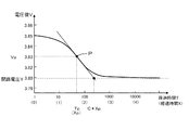
図3に、充電終了後の電圧値Vの変化を示す。図3は、SOC10%からSOC30%まで充電した後の電圧値Vの変化を示す。図3では、横軸を常用対数で表した経過時間T(つまり、経過時間X)とし、縦軸を電圧値Vとして表す。図3に示すように、充電終了タイミングにおいて、電圧値Vは開路電圧Yよりも高い値となっており、充電終了タイミング後、電圧値Vは減少を始めるとともに、負の値を有する傾きが徐々に減少する。そして、経過時間TがTpとなり、傾きが極小となる極値点Pに達すると、傾きの絶対値が最大となる。極値点P経過後、電圧値Vの傾きは増大を始め、電圧値Vは開路電圧Yへと収束する。
FIG. 3 shows a change in the voltage value V after the end of charging. FIG. 3 shows a change in the voltage value V after charging from
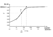
また、図4に、放電終了後の電圧値Vの変化を示す。図4は、SOC70%からSOC50%まで放電した後の電圧値Vの変化を示す。図4でも、横軸を常用対数で表した経過時間T(つまり、経過時間X)とし、縦軸を電圧値Vとして表す。図4に示すように、放電終了タイミングにおいて、電圧値Vは開路電圧Yよりも低い値となっており、放電終了タイミング後、電圧値Vは増大を始めるとともに、正の値を有する傾きが徐々に増大する。そして、経過時間TがTpとなり、傾きが極大となる極値点Pに達すると、傾きの絶対値が最大となる。極値点P経過後、電圧値Vの傾きは減少を始め、電圧値Vは開路電圧Yへと収束する。 FIG. 4 shows a change in the voltage value V after the end of discharge. FIG. 4 shows a change in voltage value V after discharging from SOC 70% to SOC 50%. Also in FIG. 4, the horizontal axis represents the elapsed time T (that is, the elapsed time X) expressed in common logarithm, and the vertical axis represents the voltage value V. As shown in FIG. 4, at the discharge end timing, the voltage value V is lower than the open circuit voltage Y. After the discharge end timing, the voltage value V starts to increase and the slope having a positive value gradually increases. To increase. Then, when the elapsed time T reaches Tp and reaches the extreme point P where the gradient becomes maximum, the absolute value of the gradient becomes maximum. After the extreme point P has elapsed, the slope of the voltage value V starts to decrease, and the voltage value V converges to the open circuit voltage Y.
つまり、図3、4に示すように、充放電終了後の電圧値Vは、開路電圧Yに到達するに先立って、傾きの絶対値が最大となる極値点Pに達し、極値点Pを経過した後に開路電圧Yへと収束する。 That is, as shown in FIGS. 3 and 4, the voltage value V after the end of charging / discharging reaches the extreme point P where the absolute value of the slope reaches the maximum before reaching the open circuit voltage Y, and the extreme point P After elapses, the voltage converges to the open circuit voltage Y.
CPU30は、経過時間Xを用いて所定時間毎に測定される電圧値Vの傾きを算出し、当該傾きの絶対値を用いて極値点Pに達したか否かを検出する。CPU30は、規定時間KTまでに測定された電圧値Vの傾きの絶対値が増大を続けている場合、極値点Pが存在しないと判断し(S12:NO)、状態推定処理を終了する。なお、電圧値Vは所定時間毎に測定されてもよければ、連続的に測定されてもよい。
The
一方、CPU30は、規定時間KTまでに測定された電圧値Vの傾きの絶対値が減少に転じる部分が存在する場合、極値点Pが存在すると判断し(S12:YES)、電圧値Vの傾きの絶対値が最大となる極値点Pを検出するとともに、極値点Pにおける温度Dpを検出する。
On the other hand, if there is a portion where the absolute value of the slope of the voltage value V measured until the specified time KT starts to decrease, the
次に、CPU30は、メモリ34から単電池14の係数Cを読み出し、算出時間Wを算出する。係数Cは、単電池14の活物質の種類に対応付けて決定される定数であり、各単電池14の極値点Pにおける係数Cとしてメモリ34に記憶されている。また、係数Cは、単電池14の温度Dに応じて定められる定数であり、単電池14の温度Dに対応付けられてメモリ34に記憶されている。例えば、正極活物質としてリチウム含有金属酸化物,負極活物質として炭素材料を用いたリチウムイオン電池では、温度Dが25℃の場合、係数Cは1.48(無単位)となり、温度Dが0℃の場合、係数Cは1.38(無単位)となる。
Next, the
CPU30は、極値点Pにおける温度Dpに対応付けられてメモリ34に記憶されている係数Cを選出し(S13)、極値点Pの経過時間XであるXpに係数Cを積した算出時間Wを算出する(S14)。
W=C*Xp
The
W = C * Xp
次に、CPU30は、極値点Pにおける近似直線の近似式を算出する(S16)。近似式を算出する方法としては、例えば、横軸を経過時間Xとし、縦軸を電圧値Vとして表したグラフにおいて、極値点Pの直前に測定された電圧値V及び経過時間Xと、極値点Pの直後に測定された電圧値V及び経過時間Xを直線で結んだものを極値点Pの近似直線とし、その近似式を算出してもよい。また、極値点Pと極値点Pの直前及び直後に測定された電圧値V及び経過時間Xに最小二乗法等の公知の方法を用いて算出された近似式を、極値点Pの近似式としてもよい。極値点Pにおける傾きをAとし、切片をBとすると、近似式は下記の式ように表される。
V=A*X+B
Next, the
V = A * X + B
次に、CPU30は、開路電圧Yを推定する(S18)。CPU30は、算出時間Wを近似式の電圧値Xに代入し、この際に得られる電圧値Vを開路電圧Yとして推定する(図3、4参照)。
Next, the
次に、CPU30は、推定した開路電圧Yから単電池14のSOCを推定する(S20)。CPU30は、メモリ34から図5に示す単電池14の開路電圧YとSOCとの相関関係表を読み出し、当該相関関係表において推定した開路電圧Yに対応つけられたSOCを単電池14のSOCとして推定する。
Next, the
なお、メモリ34に記憶されている係数Cは、同一の単電池14を用いて決定されてメモリ34に記憶されており、または同一の活物質を有する他の単電池14を用いて決定されている。係数Cを測定する場合には、単電池14の使用開始時等の任意の基準時において、充放電終了後の温度D及び電圧値Vを測定し、当該測定における極値点P(Tp、Vp)、極値点Pにおける温度Dp、極値点Pにおける近似直線の近似式、及び開路電圧Yを求めておき、上記の式を用いて決定することができる。
The coefficient C stored in the
3.本実施形態の効果
(1)本実施形態の電池システム10では、極値点Pにおける近似直線の近似式と、単電池14の活物質から決定される係数Cから開路電圧Yを推定する。そのため、極値点P及び当該極値点Pにおける近似式が得られれば、極値点P経過後、電圧値Vが開路電圧Yに収束するまで電圧値Vの測定を継続する必要がなく、開路電圧Yを早期に推定することができる。例えば、従来では、25℃において、3%程度の精度が必要な場合、電圧値Vの測定を40分程度継続して行う必要があったが、本実施形態の電池システムでは、3%程度の精度が必要な場合、電圧値Vの測定を100秒以下にまで短縮することができる。
3. Effects of the present embodiment (1) In the
特に、開路電圧Yの推定中は、単電池14の充放電ができない、いわゆる使用不能期間となる。使用不能期間が比較的長く存在すると、単電池14の使用効率が低下する。本実施形態の電池システムでは、開路電圧Y(あるいはSOC)を推定する際の使用不能期間を短縮することができ、単電池14の使用効率を向上させることができる。
In particular, during the estimation of the open circuit voltage Y, it becomes a so-called unusable period during which the
(2)本実施形態の電池システム10では、単電池14の活物質から決定される係数Cを用いて開路電圧Yを推定する。係数Cは、単電池14の活物質の種類に対応付けて決定されている定数であるので、単電池14の活物質の種類が解かっていれば、充放電毎に係数Cを求める必要がなく、開路電圧Yを早期に推定することができる。
(2) In the
(3)本実施形態の電池システム10では、温度センサ26が測定した極値点Pにおける温度Dpに基づいて係数Cを選出し、当該選出された係数Cを用いて開路電圧Yを推定するので、開路電圧Yを精度よく推定することができる。
(3) In the
(4)本実施形態の電池システム10では、規定時間TKに亘って温度D及び電圧値Vの測定を継続した後に、温度D及び電圧値Vの測定を終了するので、電圧値Vが開路電圧Yに収束するまで電圧値Vの測定を継続する場合に比べて、開路電圧Yを早期に推定することができる。
(4) In the
(5)本実施形態の電池システム10では、電流センサ22が検出する電流値Iがゼロとなるタイミングから充放電終了タイミングを検出するので、充放電終了タイミングを正確に検出することができる。
(5) In the
(6)本実施形態の電池システム10では、極値点Pにおける近似直線の近似式と、単電池14の活物質から決定される係数Cとを用いて早期に推定される開路電圧Yを用いて単電池14のSOCを推定するので、単電池14のSOCを早期に推定することができる。
(6) In the
<他の実施形態>
本明細書が開示する技術は上記記述及び図面によって説明した実施形態に限定されるものではなく、例えば次のような種々の態様も本発明の技術的範囲に含まれる。
(1)上記実施形態では、蓄電素子の一例として二次電池の単電池14を示したが、これに限らず、蓄電素子は、電気化学現象を伴うキャパシタ等であってもよい。
<Other embodiments>
The technology disclosed in the present specification is not limited to the embodiments described with reference to the above description and drawings, and for example, the following various aspects are also included in the technical scope of the present invention.
(1) In the above embodiment, the
(2)上記実施形態では、極値点Pにおける近似直線の近似式と、極値点Pにおける係数Cから開路電圧Yを推定する例を用いて説明を行った。しかし、組電池12への充放電終了後、近似直線を求めるタイミングは極値点Pに限られず、電圧値Vが開路電圧Yに収束するまでの任意のタイミングにおける近似直線の近似式から開路電圧Yを推定してもよい。
(2) The above embodiment has been described using an example of estimating the open circuit voltage Y from the approximate expression of the approximate line at the extreme point P and the coefficient C at the extreme point P. However, the timing for obtaining the approximate line after completion of charging / discharging to the assembled
この場合、係数Cは、単電池14の活物質、温度Dに加え、充放電終了タイミングからの経過時間T(X)に対応付けられてメモリ34に記憶されている。CPU30は、近似直線の近似式が算出されると、当該近似直線に係る経過時間Tに対応付けてメモリ34に記憶されている係数Cを選出し、算出時間Wを算出する。そして、当該近似式と算出時間Wから開路電圧Yを推定する
In this case, the coefficient C is stored in the
(3)上記実施形態では、図3,4に示すように、電圧値Vの近似直線を設定する際に、経過時間Tを常用対数で表した経過時間Xとの関係において、近似直線を設定し、その近似式を求める例を用いて説明を行った。しかし、近似直線を設定する際に、経過時間Tをそのまま用いてもよければ、経過時間Tを自然対数で表したものとの関係において、近似直線を設定してもよい。 (3) In the above embodiment, as shown in FIGS. 3 and 4, when setting the approximate line of the voltage value V, the approximate line is set in relation to the elapsed time X in which the elapsed time T is expressed as a common logarithm. The description is given using an example of obtaining the approximate expression. However, if the elapsed time T can be used as it is when setting the approximate line, the approximate line may be set in relation to the elapsed time T expressed in natural logarithm.
(4)上記実施形態では、推定された単電池14の開路電圧Yから当該単電池14のSOCを推定する際に、開路電圧YとSOCとの相関関係表を用いてSOCを推定する例を用いて説明を行った。しかし、SOCを推定する方法は、これに限られず、開路電圧YからSOCを推定する公知の方法を利用することができる。
(4) In the said embodiment, when estimating SOC of the said
(5)上記実施形態では、充放電終了タイミングを検出するのに、BMS20が有する電流センサ22が測定する組電池12の電流値Iがゼロとなるタイミングを充放電終了タイミングとして検出する例を用いて説明を行った。しかし、充放電終了タイミングを検出する方法は、これに限られず、例えば電池システム10を管理する管理装置から入力されるシステムステータス情報等に基づいて充放電終了タイミングを検出してもよい。
(5) In the above embodiment, an example in which the timing at which the current value I of the assembled
(6)上記実施形態では、係数Cが極値点Pにおける温度Dpに基づいて選出される例を用いて説明を行ったが、必ずしも温度Dpに基づいて選出されなくてもよい。また、係数Cの選出に関わる温度Dは、極値点Pにおける温度Dpにも限られず、充放電終了タイミング後、極値点Pが測定される経過時間Xpまでに測定された単電池14の温度Dに基づいて係数Cを選出してもよい。
(6) In the above embodiment, the description has been given using the example in which the coefficient C is selected based on the temperature Dp at the extreme point P. However, the coefficient C need not necessarily be selected based on the temperature Dp. Further, the temperature D related to the selection of the coefficient C is not limited to the temperature Dp at the extreme point P, but after the end of charging / discharging, the temperature of the
(7)上記実施形態では、制御部の一例として、1つのCPU32等を備える制御ユニット30を例挙げた。しかし、制御部は、複数のCPUを備える構成や、ASIC(Application Specific Integrated Circuit)などのハード回路を備える構成や、ハード回路及びCPUの両方を備える構成でもよい。要するに、制御部は、上記の状態推定処理を、ソフト処理またはハード回路を利用して実行するものであればよい。
(7) In the said embodiment, the
(8)さらには、必ずしも状態推定処理の全ての処理を実行しなくてもよい。例えば、SOCを推定する処理(S20)を除いたものは、単電池14の開路電圧Yを推定する開路電圧推定処理として利用することができる。
(8) Furthermore, it is not always necessary to execute all of the state estimation processing. For example, the processing except for the process of estimating the SOC (S20) can be used as an open circuit voltage estimation process for estimating the open circuit voltage Y of the
(9)上記実施形態では、CPU30が読み込んで実行するプログラムとして、メモリ34に記憶されたものを例に挙げた。しかし、プログラムは、これに限らず、ハードディスク装置、フラッシュメモリ(登録商標)などの不揮発性メモリや、CD−Rなどの記憶媒体などに記憶されたものでもよい。また、メモリ34は、必ずしも制御ユニット30の内部に設けられる必要はなく、制御ユニット30の外部に設けられていてもよい。
(9) In the above embodiment, the program stored in the
10:電池システム、12:組電池、14:単電池、20:BMS、22:電流センサ、24:電圧測定回路、26:温度センサ、30:制御ユニット、32:CPU、34:メモリ、36:ADC、C:係数、D:温度、I:電流値、P:極値点、T:経過時間、V:電圧値、W:算出時間 10: battery system, 12: assembled battery, 14: single battery, 20: BMS, 22: current sensor, 24: voltage measurement circuit, 26: temperature sensor, 30: control unit, 32: CPU, 34: memory, 36: ADC, C: coefficient, D: temperature, I: current value, P: extreme point, T: elapsed time, V: voltage value, W: calculation time
Claims (13)
前記蓄電素子の端子電圧を測定する電圧測定部と、
制御部と、
を備え、
前記制御部は、
前記蓄電素子の充放電終了後に前記端子電圧を測定し、前記蓄電素子の充放電終了タイミングからの経過時間に関連付けて記憶する電圧測定処理と、
前記蓄電素子の充放電終了後から所定の経過時間における前記端子電圧の近似直線の近似式を算出する直線算出処理と、
前記所定の経過時間と、前記蓄電素子の活物質及び前記所定の経過時間に応じて定められた係数とから算出時間を算出する時間算出処理と、
前記近似式に前記算出時間を代入したものを前記開路電圧として推定する電圧推定処理と、
を実行する構成を有する、開路電圧推定装置。 An open circuit voltage estimation device for estimating an open circuit voltage of a storage element,
A voltage measuring unit for measuring a terminal voltage of the power storage element;
A control unit;
With
The controller is
A voltage measurement process for measuring the terminal voltage after completion of charging and discharging of the storage element, and storing the terminal voltage in association with an elapsed time from the charging and discharging end timing of the storage element;
A straight line calculation process for calculating an approximate expression of the approximate straight line of the terminal voltage at a predetermined elapsed time from the end of charging and discharging of the storage element;
A time calculation process for calculating a calculation time from the predetermined elapsed time and a coefficient determined according to the active material of the power storage element and the predetermined elapsed time;
A voltage estimation process for estimating the open circuit voltage obtained by substituting the calculation time into the approximate expression;
The open circuit voltage estimation apparatus which has the structure which performs.
前記直線算出処理において、前記経過時間を常用対数で表した値を用いて前記近似式を算出する構成を有する、開路電圧推定装置。 An open-circuit voltage estimation device according to claim 1,
In the straight line calculation process, an open circuit voltage estimation device having a configuration for calculating the approximate expression using a value representing the elapsed time in a common logarithm.
前記制御部は、
前記端子電圧の傾きの絶対値が最も大きくなる極値点を検出する極値点検出処理を更に実行し、
前記直線算出処理及び前記時間算出処理では、前記蓄電素子の充放電終了後から前記極値点までの経過時間を前記所定の経過時間として処理を実行する構成を有する、開路電圧推定装置。 An open-circuit voltage estimation device according to claim 1 or 2,
The controller is
An extreme point detection process for detecting an extreme point where the absolute value of the slope of the terminal voltage is the largest is further executed.
In the straight line calculation process and the time calculation process, the open circuit voltage estimation apparatus has a configuration in which the process is executed using the elapsed time from the end of charging and discharging of the power storage element to the extreme point as the predetermined elapsed time.
前記蓄電素子の温度を測定する温度測定部を更に備え、
前記係数は、前記蓄電素子の温度に応じて定められており、
前記制御部は、
前記時間算出処理において、前記所定の経過時間における前記蓄電素子の温度に応じて前記係数を決定して前記算出時間を算出する構成を有する、開路電圧推定装置。 An open-circuit voltage estimation device according to any one of claims 1 to 3,
A temperature measuring unit for measuring the temperature of the electricity storage element;
The coefficient is determined according to the temperature of the power storage element,
The controller is
In the time calculation process, the open circuit voltage estimation device has a configuration in which the coefficient is determined according to the temperature of the power storage element at the predetermined elapsed time to calculate the calculation time.
前記制御部は、
前記電圧測定処理において、前記経過時間が予め定められた規定時間経過したことを条件に、前記端子電圧の測定を終了する構成を有する、開路電圧推定装置。 An open-circuit voltage estimation device according to any one of claims 1 to 4,
The controller is
In the voltage measurement process, the open circuit voltage estimation device has a configuration in which the measurement of the terminal voltage is terminated on condition that the predetermined time has elapsed in advance.
前記蓄電素子の充放電電流を検出する電流検出部を更に備え、
前記制御部は、
前記電圧測定処理において、前記電流検出部の検出結果から、前記充放電終了タイミングを検出する構成を有する、開路電圧推定装置。 An open-circuit voltage estimation device according to any one of claims 1 to 5,
A current detection unit for detecting a charge / discharge current of the power storage element;
The controller is
In the voltage measurement process, the open circuit voltage estimation device has a configuration for detecting the charge / discharge end timing from the detection result of the current detection unit.
請求項1ないし請求項6のいずれか一項に記載の開路電圧推定装置と、
前記蓄電素子の開路電圧と内部状態との相関関係に関する情報が記憶されるメモリと、
を備え、
前記制御部は、
前記電圧推定処理で推定された前記開路電圧と、前記メモリに記憶された前記相関関係に関する情報から前記蓄電素子の内部状態を推定する状態推定処理を更に実行する構成を有する、状態推定装置。 A state estimation device for estimating an internal state of a storage element,
An open circuit voltage estimation device according to any one of claims 1 to 6,
A memory for storing information on a correlation between an open circuit voltage of the power storage element and an internal state;
With
The controller is
The state estimation apparatus which has the structure which further performs the state estimation process which estimates the internal state of the said electrical storage element from the said open circuit voltage estimated by the said voltage estimation process, and the information regarding the said correlation memorize | stored in the said memory.
前記蓄電素子の充放電終了後に前記蓄電素子の端子電圧を測定し、前記蓄電素子の充放電終了タイミングからの経過時間に関連付けて記憶する電圧測定工程と、
前記蓄電素子の充放電終了後から所定の経過時間における前記端子電圧の近似直線の近似式を算出する直線算出工程と、
前記所定の経過時間と、前記蓄電素子の活物質及び前記所定の経過時間に応じて定められた係数とから算出時間を算出する時間算出工程と、
前記近似式に前記算出時間を代入したものを前記開路電圧として推定する電圧推定工程と、
を備える、開路電圧推定方法。 An open circuit voltage estimation method for estimating an open circuit voltage of a storage element,
A voltage measuring step of measuring a terminal voltage of the power storage element after completion of charge / discharge of the power storage element, and storing the voltage in association with an elapsed time from a charge / discharge end timing of the power storage element;
A straight line calculating step of calculating an approximate expression of an approximate straight line of the terminal voltage at a predetermined elapsed time from the end of charging and discharging of the storage element;
A time calculation step of calculating a calculation time from the predetermined elapsed time and a coefficient determined according to the active material of the power storage element and the predetermined elapsed time;
A voltage estimation step of estimating the open circuit voltage by substituting the calculation time into the approximate expression;
An open circuit voltage estimation method comprising:
前記直線算出工程において、前記経過時間を常用対数で表した値を用いて前記近似式を算出する、開路電圧推定方法。 An open circuit voltage estimation method according to claim 8,
An open circuit voltage estimation method in which, in the straight line calculation step, the approximate expression is calculated using a value representing the elapsed time in a common logarithm.
前記端子電圧の傾きの絶対値が最も大きくなる極値点を検出する極値点検出工程を更に備え、
前記直線算出工程及び前記時間算出工程において、前記蓄電素子の充放電終了後から前記極値点までの経過時間を前記所定の経過時間として処理を実行する、開路電圧推定方法。 An open circuit voltage estimation method according to claim 8 or 9, wherein
An extreme point detection step of detecting an extreme point where the absolute value of the slope of the terminal voltage is the largest, further comprising:
An open circuit voltage estimation method, wherein, in the straight line calculation step and the time calculation step, processing is performed with an elapsed time from the end of charge / discharge of the power storage element to the extreme point as the predetermined elapsed time.
前記係数は、前記蓄電素子の温度に応じて定められており、
前記時間算出工程において、前記所定の経過時間における前記蓄電素子の温度に応じて前記係数を決定して前記算出時間を算出する、開路電圧推定方法。 An open circuit voltage estimation method according to any one of claims 8 to 10,
The coefficient is determined according to the temperature of the power storage element,
An open circuit voltage estimation method, wherein, in the time calculation step, the calculation time is calculated by determining the coefficient according to a temperature of the power storage element at the predetermined elapsed time.
前記電圧測定工程において、前記経過時間が予め定められた規定時間経過したことを条件に、前記端子電圧の測定を終了する、開路電圧推定方法。 An open circuit voltage estimation method according to any one of claims 8 to 11,
An open circuit voltage estimation method in which, in the voltage measurement step, the measurement of the terminal voltage is terminated on condition that the elapsed time has passed a predetermined time.
前記電圧測定工程において、前記蓄電素子の充放電電流を検出した結果から、前記充放電終了タイミングを検出する、開路電圧推定方法。 An open circuit voltage estimation method according to any one of claims 8 to 12,
An open circuit voltage estimation method for detecting the charge / discharge end timing from a result of detecting a charge / discharge current of the power storage element in the voltage measurement step.
Priority Applications (5)
| Application Number | Priority Date | Filing Date | Title |
|---|---|---|---|
| JP2012113271A JP6066163B2 (en) | 2012-05-17 | 2012-05-17 | Open circuit voltage estimation device, state estimation device, and open circuit voltage estimation method |
| KR1020130044011A KR101996974B1 (en) | 2012-05-17 | 2013-04-22 | Open circuit voltage estimation device, state estimation device, method of open circuit voltage estimation |
| CN201310142247.2A CN103424708B (en) | 2012-05-17 | 2013-04-23 | Open-circuit voltage apparatus for predicting, device for estimating state and open-circuit voltage estimating method |
| US13/897,115 US10901039B2 (en) | 2012-05-17 | 2013-05-17 | Open circuit voltage estimation device, condition estimation device, and method of estimating open circuit voltage |
| EP13168298.1A EP2664938B1 (en) | 2012-05-17 | 2013-05-17 | Open circuit voltage estimation device, condition estimation device, and method of estimating open circuit voltage |
Applications Claiming Priority (1)
| Application Number | Priority Date | Filing Date | Title |
|---|---|---|---|
| JP2012113271A JP6066163B2 (en) | 2012-05-17 | 2012-05-17 | Open circuit voltage estimation device, state estimation device, and open circuit voltage estimation method |
Publications (2)
| Publication Number | Publication Date |
|---|---|
| JP2013238564A true JP2013238564A (en) | 2013-11-28 |
| JP6066163B2 JP6066163B2 (en) | 2017-01-25 |
Family
ID=48538960
Family Applications (1)
| Application Number | Title | Priority Date | Filing Date |
|---|---|---|---|
| JP2012113271A Active JP6066163B2 (en) | 2012-05-17 | 2012-05-17 | Open circuit voltage estimation device, state estimation device, and open circuit voltage estimation method |
Country Status (5)
| Country | Link |
|---|---|
| US (1) | US10901039B2 (en) |
| EP (1) | EP2664938B1 (en) |
| JP (1) | JP6066163B2 (en) |
| KR (1) | KR101996974B1 (en) |
| CN (1) | CN103424708B (en) |
Cited By (3)
| Publication number | Priority date | Publication date | Assignee | Title |
|---|---|---|---|---|
| JP2018156759A (en) * | 2017-03-16 | 2018-10-04 | プライムアースEvエナジー株式会社 | State determination method of secondary cell and state determination device of secondary cell |
| JPWO2018173174A1 (en) * | 2017-03-22 | 2019-04-04 | 中国電力株式会社 | Inlet valve operation detection system and inlet valve operation detection method |
| WO2021091086A1 (en) * | 2019-11-05 | 2021-05-14 | 주식회사 엘지화학 | Battery diagnosis device, battery diagnosis method and energy storage system |
Families Citing this family (8)
| Publication number | Priority date | Publication date | Assignee | Title |
|---|---|---|---|---|
| DE102012013405A1 (en) * | 2012-07-05 | 2014-01-09 | Audi Ag | Diagnostic device for checking a control signal line |
| CN103983833B (en) * | 2014-05-28 | 2016-10-05 | 山东大学 | Battery open circuit voltage Forecasting Methodology based on GM (1,1) gray model |
| US10282874B2 (en) * | 2014-09-17 | 2019-05-07 | Circonus, Inc. | Efficient time-series histograms |
| US10365334B2 (en) * | 2015-05-25 | 2019-07-30 | Nec Corporation | Storage battery control device, power storage system, control method, and computer-readable medium |
| DE102016223326A1 (en) * | 2016-02-04 | 2017-08-10 | Siemens Aktiengesellschaft | Method for determining the aging of an electrochemical store |
| CN106338646A (en) * | 2016-10-12 | 2017-01-18 | 上海信耀电子有限公司 | Automobile lead acid cell open-circuit voltage (OCV) calculation method and system |
| FR3104728B1 (en) | 2019-12-11 | 2021-12-10 | Electricite De France | Diagnosis of energy storage systems in operation |
| CN114460475B (en) * | 2022-04-12 | 2022-07-22 | 深圳市思远半导体有限公司 | Battery OCV determining method and device and battery SOC estimating method |
Citations (3)
| Publication number | Priority date | Publication date | Assignee | Title |
|---|---|---|---|---|
| JPH04134279A (en) * | 1990-09-27 | 1992-05-08 | Yuasa Corp | Open circuit voltage measuring method for lead acid battery |
| JP2002250757A (en) * | 2001-02-23 | 2002-09-06 | Yazaki Corp | Method and apparatus for estimating open circuit voltage of vehicle battery |
| JP2009234557A (en) * | 2007-11-14 | 2009-10-15 | Autonetworks Technologies Ltd | Open voltage value estimation method and open voltage value estimation apparatus |
Family Cites Families (17)
| Publication number | Priority date | Publication date | Assignee | Title |
|---|---|---|---|---|
| US4344142A (en) * | 1974-05-23 | 1982-08-10 | Federal-Mogul Corporation | Direct digital control of rubber molding presses |
| US4514694A (en) * | 1981-07-23 | 1985-04-30 | Curtis Instruments | Quiescent battery testing method and apparatus |
| JPH0798367A (en) | 1993-09-28 | 1995-04-11 | Honda Motor Co Ltd | Battery remaining capacity estimation method |
| JP2810630B2 (en) * | 1993-11-16 | 1998-10-15 | キヤノン株式会社 | Solar cell power control device, power control system, power control method, and voltage / current output characteristic measurement method |
| US6313605B1 (en) * | 1998-12-08 | 2001-11-06 | Total Battery Management, Inc. | Battery charger and method of charging nickel based batteries |
| DE10207659B4 (en) * | 2001-02-23 | 2006-09-28 | Yazaki Corp. | A method and apparatus for estimating a terminal voltage of a battery, method and apparatus for calculating an open circuit voltage of a battery, and method and apparatus for calculating battery capacity |
| JP4078880B2 (en) * | 2002-05-24 | 2008-04-23 | 日産自動車株式会社 | Power storage system |
| CN100520431C (en) * | 2003-07-29 | 2009-07-29 | 松下电动车辆能源股份有限公司 | Method and device for estimating charge/discharge electric quantity of secondary battery |
| KR100805116B1 (en) | 2006-09-08 | 2008-02-21 | 삼성에스디아이 주식회사 | Battery management system and its driving method |
| KR100985667B1 (en) * | 2007-08-22 | 2010-10-05 | 주식회사 엘지화학 | Battery open circuit voltage estimator, battery charge state estimator and its control method |
| JP2009072020A (en) * | 2007-09-14 | 2009-04-02 | Calsonic Kansei Corp | Internal state estimating device of secondary battery |
| JP4459997B2 (en) * | 2007-11-06 | 2010-04-28 | 株式会社日本自動車部品総合研究所 | On-vehicle battery state estimation device, internal combustion engine automatic stop / start device, and internal combustion engine automatic stop / start system |
| JP5262179B2 (en) | 2008-02-26 | 2013-08-14 | 日産自動車株式会社 | Secondary battery charging rate estimation device and charging rate estimation method |
| JP4702859B2 (en) * | 2008-04-11 | 2011-06-15 | 古河電気工業株式会社 | Battery status detection method |
| KR101187766B1 (en) * | 2008-08-08 | 2012-10-05 | 주식회사 엘지화학 | Apparatus and Method for cell balancing based on battery's voltage variation pattern |
| JP2010200574A (en) | 2009-02-27 | 2010-09-09 | Panasonic Corp | Self-diagnosis circuit and power supply |
| JP2010203854A (en) | 2009-03-02 | 2010-09-16 | Nissan Motor Co Ltd | Device of estimating internal state of secondary battery |
-
2012
- 2012-05-17 JP JP2012113271A patent/JP6066163B2/en active Active
-
2013
- 2013-04-22 KR KR1020130044011A patent/KR101996974B1/en active Active
- 2013-04-23 CN CN201310142247.2A patent/CN103424708B/en active Active
- 2013-05-17 EP EP13168298.1A patent/EP2664938B1/en active Active
- 2013-05-17 US US13/897,115 patent/US10901039B2/en active Active
Patent Citations (3)
| Publication number | Priority date | Publication date | Assignee | Title |
|---|---|---|---|---|
| JPH04134279A (en) * | 1990-09-27 | 1992-05-08 | Yuasa Corp | Open circuit voltage measuring method for lead acid battery |
| JP2002250757A (en) * | 2001-02-23 | 2002-09-06 | Yazaki Corp | Method and apparatus for estimating open circuit voltage of vehicle battery |
| JP2009234557A (en) * | 2007-11-14 | 2009-10-15 | Autonetworks Technologies Ltd | Open voltage value estimation method and open voltage value estimation apparatus |
Cited By (4)
| Publication number | Priority date | Publication date | Assignee | Title |
|---|---|---|---|---|
| JP2018156759A (en) * | 2017-03-16 | 2018-10-04 | プライムアースEvエナジー株式会社 | State determination method of secondary cell and state determination device of secondary cell |
| JPWO2018173174A1 (en) * | 2017-03-22 | 2019-04-04 | 中国電力株式会社 | Inlet valve operation detection system and inlet valve operation detection method |
| WO2021091086A1 (en) * | 2019-11-05 | 2021-05-14 | 주식회사 엘지화학 | Battery diagnosis device, battery diagnosis method and energy storage system |
| US11796599B2 (en) | 2019-11-05 | 2023-10-24 | Lg Energy Solution, Ltd. | Battery diagnosis apparatus, battery diagnosis method and energy storage system |
Also Published As
| Publication number | Publication date |
|---|---|
| US20130311118A1 (en) | 2013-11-21 |
| EP2664938A2 (en) | 2013-11-20 |
| EP2664938B1 (en) | 2016-11-23 |
| CN103424708A (en) | 2013-12-04 |
| CN103424708B (en) | 2017-12-22 |
| EP2664938A3 (en) | 2015-07-22 |
| KR101996974B1 (en) | 2019-07-05 |
| JP6066163B2 (en) | 2017-01-25 |
| KR20130129096A (en) | 2013-11-27 |
| US10901039B2 (en) | 2021-01-26 |
Similar Documents
| Publication | Publication Date | Title |
|---|---|---|
| JP6066163B2 (en) | Open circuit voltage estimation device, state estimation device, and open circuit voltage estimation method | |
| JP6155830B2 (en) | State estimation device and state estimation method | |
| EP2711727B1 (en) | Battery condition estimation device and method of generating open circuit voltage characteristic | |
| JP6119402B2 (en) | Internal resistance estimation device and internal resistance estimation method | |
| JP6477733B2 (en) | Charge state estimation device | |
| US11022653B2 (en) | Deterioration degree estimation device and deterioration degree estimation method | |
| JP5397679B2 (en) | Secondary battery deterioration diagnosis method and secondary battery deterioration diagnosis device | |
| JP6300000B2 (en) | Charge state estimation device, charge state estimation method | |
| US9983270B2 (en) | State of charge estimation device and method of estimating state of charge | |
| WO2007074614A1 (en) | Charged state estimation device and charged state estimation method of secondary battery | |
| JP2018146372A (en) | Storage battery deterioration determination method and storage battery deterioration determination device | |
| JP2012108139A (en) | Remaining capacitance detector for battery | |
| CN104335057A (en) | Method and apparatus for determining the actual capacity of a battery | |
| JP5911407B2 (en) | Battery soundness calculation device and soundness calculation method | |
| JPWO2019230131A1 (en) | Charge control devices, transportation equipment, and programs | |
| JP2014109535A (en) | Internal resistance estimation device, charging apparatus, discharging apparatus, and internal resistance estimation method | |
| CN112415409A (en) | Method and device for estimating battery capacity, storage medium and vehicle | |
| JP5904916B2 (en) | Battery soundness calculation device and soundness calculation method | |
| JP5999409B2 (en) | State estimation device and state estimation method | |
| JP2010197354A (en) | Capacity estimating device for secondary battery | |
| JP2014059251A (en) | Internal resistance estimation device and internal resistance estimation method | |
| WO2014038555A1 (en) | Battery state-of-charge detection device, battery system, battery state-of-charge detection method, and program | |
| JP2003047165A (en) | Battery charger | |
| JP2019070622A (en) | Secondary battery system | |
| CN121175583A (en) | Battery diagnosis device and battery diagnosis method |
Legal Events
| Date | Code | Title | Description |
|---|---|---|---|
| A621 | Written request for application examination |
Free format text: JAPANESE INTERMEDIATE CODE: A621 Effective date: 20150421 |
|
| A977 | Report on retrieval |
Free format text: JAPANESE INTERMEDIATE CODE: A971007 Effective date: 20160324 |
|
| A131 | Notification of reasons for refusal |
Free format text: JAPANESE INTERMEDIATE CODE: A131 Effective date: 20160329 |
|
| A521 | Request for written amendment filed |
Free format text: JAPANESE INTERMEDIATE CODE: A523 Effective date: 20160527 |
|
| A131 | Notification of reasons for refusal |
Free format text: JAPANESE INTERMEDIATE CODE: A131 Effective date: 20160628 |
|
| A131 | Notification of reasons for refusal |
Free format text: JAPANESE INTERMEDIATE CODE: A131 Effective date: 20161004 |
|
| TRDD | Decision of grant or rejection written | ||
| A01 | Written decision to grant a patent or to grant a registration (utility model) |
Free format text: JAPANESE INTERMEDIATE CODE: A01 Effective date: 20161201 |
|
| A61 | First payment of annual fees (during grant procedure) |
Free format text: JAPANESE INTERMEDIATE CODE: A61 Effective date: 20161214 |
|
| R150 | Certificate of patent or registration of utility model |
Ref document number: 6066163 Country of ref document: JP Free format text: JAPANESE INTERMEDIATE CODE: R150 |