JP2013201848A - Non contact power transmission apparatus and method - Google Patents
Non contact power transmission apparatus and method Download PDFInfo
- Publication number
- JP2013201848A JP2013201848A JP2012069247A JP2012069247A JP2013201848A JP 2013201848 A JP2013201848 A JP 2013201848A JP 2012069247 A JP2012069247 A JP 2012069247A JP 2012069247 A JP2012069247 A JP 2012069247A JP 2013201848 A JP2013201848 A JP 2013201848A
- Authority
- JP
- Japan
- Prior art keywords
- power
- coil
- duty
- relative position
- metal member
- Prior art date
- Legal status (The legal status is an assumption and is not a legal conclusion. Google has not performed a legal analysis and makes no representation as to the accuracy of the status listed.)
- Granted
Links
Images


Classifications
-
- H—ELECTRICITY
- H02—GENERATION; CONVERSION OR DISTRIBUTION OF ELECTRIC POWER
- H02J—ELECTRIC POWER NETWORKS; CIRCUIT ARRANGEMENTS OR SYSTEMS FOR SUPPLYING OR DISTRIBUTING ELECTRIC POWER; SYSTEMS FOR STORING ELECTRIC ENERGY
- H02J50/00—Circuit arrangements or systems for wireless supply or distribution of electric power
- H02J50/90—Circuit arrangements or systems for wireless supply or distribution of electric power involving detection or optimisation of position, e.g. alignment
-
- G—PHYSICS
- G01—MEASURING; TESTING
- G01B—MEASURING LENGTH, THICKNESS OR SIMILAR LINEAR DIMENSIONS; MEASURING ANGLES; MEASURING AREAS; MEASURING IRREGULARITIES OF SURFACES OR CONTOURS
- G01B7/00—Measuring arrangements characterised by the use of electric or magnetic techniques
- G01B7/14—Measuring arrangements characterised by the use of electric or magnetic techniques for measuring distance or clearance between spaced objects or spaced apertures
-
- H—ELECTRICITY
- H01—ELECTRIC ELEMENTS
- H01F—MAGNETS; INDUCTANCES; TRANSFORMERS; SELECTION OF MATERIALS FOR THEIR MAGNETIC PROPERTIES
- H01F38/00—Adaptations of transformers or inductances for specific applications or functions
- H01F38/14—Inductive couplings
-
- H—ELECTRICITY
- H02—GENERATION; CONVERSION OR DISTRIBUTION OF ELECTRIC POWER
- H02J—ELECTRIC POWER NETWORKS; CIRCUIT ARRANGEMENTS OR SYSTEMS FOR SUPPLYING OR DISTRIBUTING ELECTRIC POWER; SYSTEMS FOR STORING ELECTRIC ENERGY
- H02J50/00—Circuit arrangements or systems for wireless supply or distribution of electric power
- H02J50/10—Circuit arrangements or systems for wireless supply or distribution of electric power using inductive coupling
- H02J50/12—Circuit arrangements or systems for wireless supply or distribution of electric power using inductive coupling of the resonant type
-
- H—ELECTRICITY
- H02—GENERATION; CONVERSION OR DISTRIBUTION OF ELECTRIC POWER
- H02M—APPARATUS FOR CONVERSION BETWEEN AC AND AC, BETWEEN AC AND DC, OR BETWEEN DC AND DC, AND FOR USE WITH MAINS OR SIMILAR POWER SUPPLY SYSTEMS; CONVERSION OF DC OR AC INPUT POWER INTO SURGE OUTPUT POWER; CONTROL OR REGULATION THEREOF
- H02M3/00—Conversion of DC power input into DC power output
- H02M3/22—Conversion of DC power input into DC power output with intermediate conversion into AC
- H02M3/24—Conversion of DC power input into DC power output with intermediate conversion into AC by static converters
- H02M3/28—Conversion of DC power input into DC power output with intermediate conversion into AC by static converters using discharge tubes with control electrode or semiconductor devices with control electrode to produce the intermediate AC
- H02M3/325—Conversion of DC power input into DC power output with intermediate conversion into AC by static converters using discharge tubes with control electrode or semiconductor devices with control electrode to produce the intermediate AC using devices of a triode or a transistor type requiring continuous application of a control signal
- H02M3/335—Conversion of DC power input into DC power output with intermediate conversion into AC by static converters using discharge tubes with control electrode or semiconductor devices with control electrode to produce the intermediate AC using devices of a triode or a transistor type requiring continuous application of a control signal using semiconductor devices only
- H02M3/33569—Conversion of DC power input into DC power output with intermediate conversion into AC by static converters using discharge tubes with control electrode or semiconductor devices with control electrode to produce the intermediate AC using devices of a triode or a transistor type requiring continuous application of a control signal using semiconductor devices only having several active switching elements
- H02M3/33573—Full-bridge at primary side of an isolation transformer
Landscapes
- Engineering & Computer Science (AREA)
- Power Engineering (AREA)
- Computer Networks & Wireless Communication (AREA)
- Physics & Mathematics (AREA)
- General Physics & Mathematics (AREA)
- Charge And Discharge Circuits For Batteries Or The Like (AREA)
Abstract
Description
本発明は、電力の伝送を非接触で行う非接触電力伝送装置及び方法に関する。 The present invention relates to a contactless power transmission apparatus and method that perform power transmission in a contactless manner.
非接触電力伝送装置は、電力を伝送するための配線(ケーブル)が不要であり接続の手間が省ける、接点の耐久性や接点不良を考慮する必要が無い等の様々なメリットがある。このため、近年では、家庭用電化製品等の民生用機器に設けられたバッテリを充電するための電力を伝送する用途のみならず、産業用機器(例えば、ステージ、アーム、クレーン、ロボット等)を駆動する電力を伝送する用途にも用いられている。 The non-contact power transmission device has various merits such as no need for wiring (cable) for transmitting power, saving the connection, and no need to consider contact durability and contact failure. For this reason, in recent years, not only uses for transmitting power for charging batteries provided in consumer devices such as household appliances, but also industrial devices (for example, stages, arms, cranes, robots, etc.) It is also used for transmitting driving power.
以下の特許文献1には、半導体製造装置における搬送装置に対して非接触で電力を伝送する非接触電力伝送装置が開示されている。具体的には、搬送台の移動経路である搬送路に設定された停止位置に搬送台が停止したときに、停止位置に設けられた電圧供給装置から停止状態にある搬送台に対して電磁誘導の作用によって電力を供給する技術が開示されている。また、以下の特許文献2,3には、携帯電話機等の民生用機器や車両等の移動体に対して非接触で電力を伝送する非接触電力伝送装置が開示されている。
上述した産業用機器を駆動する電力を伝送する用途においては、給電対象機器(ステージやアーム等)の可動部が動いている状態(例えば、直線動や回転動している状態)で非接触電力伝送装置から給電対象機器へ電力伝送が行われる場合がある。 In the application of transmitting power for driving industrial equipment as described above, non-contact power when the movable part of the power supply target equipment (stage, arm, etc.) is moving (for example, linear motion or rotational motion). In some cases, power transmission is performed from the transmission device to the power supply target device.
また、このような給電対象機器は、その一部に金属部材を有するものも多い。
しかし可動部に対して電力を伝送する場合には、可動部が動くことによって、非接触電力伝送装置の給電コイルと可動部に設けられた受電コイルとの相対位置が変化し、給電コイルから受電コイルへ電力を伝送している電磁界の分布も変化する。電磁界の分布が金属部材に近づき金属部材周辺の電磁界が強くなると、金属部材に誘導電流が流れ、非接触電力伝送の効率が低下するだけでなく、金属部材が過熱され金属部材に取り付けられている装置や部品の動作不良や故障の原因となる可能性がある。
In addition, such power supply target devices often have a metal member in a part thereof.
However, when power is transmitted to the movable part, the relative position between the power feeding coil of the non-contact power transmission device and the power receiving coil provided in the movable part changes as the movable part moves, and power is received from the power feeding coil. The distribution of the electromagnetic field transmitting power to the coil also changes. When the electromagnetic field distribution approaches the metal member and the electromagnetic field around the metal member becomes stronger, not only does the induction current flow through the metal member and the efficiency of contactless power transmission decreases, but the metal member is overheated and attached to the metal member. It may cause malfunction or failure of the equipment and components that are installed.
本発明は、かかる問題点を解消するために創案されたものである。すなわち、本発明の目的は、給電コイルと受電コイルとの相対的な位置関係が変化しても金属部材に流れる誘導電流を制限し、金属部材の過熱を抑制することができる非接触電力伝送装置及び方法を提供することにある。 The present invention has been developed to solve such problems. That is, an object of the present invention is to provide a non-contact power transmission apparatus that can limit the induced current flowing through the metal member even if the relative positional relationship between the power feeding coil and the power receiving coil changes, and suppress overheating of the metal member. And providing a method.
本発明によれば、給電コイルと受電コイル間で電力を非接触で伝送する非接触電力伝送装置であって、
前記給電コイルに前記電力を供給する給電部と、
受電コイルの給電コイルに対する相対位置を測定する測定部と、
前記給電部を制御する制御部とを備え、
制御部は、測定部で測定された前記相対位置に応じて金属部材に流れる誘導電流が小さくなるように前記電力を変化させる、ことを特徴とする非接触電力伝送装置が提供される。
According to the present invention, a non-contact power transmission device that transmits power in a non-contact manner between a power feeding coil and a power receiving coil,
A power supply unit for supplying the power to the power supply coil;
A measurement unit for measuring a relative position of the power receiving coil with respect to the power supply coil;
A control unit for controlling the power feeding unit,
The control unit changes the power so that the induced current flowing through the metal member is reduced according to the relative position measured by the measurement unit.
また、本発明によれば、給電コイルと受電コイル間で電力を非接触で伝送する非接触電力伝送方法であって、
給電部により、前記給電コイルに前記電力を供給し、
測定部により、受電コイルの給電コイルに対する相対位置を測定し、
制御部により、測定部で測定された前記相対位置に応じて金属部材に流れる誘導電流が小さくなるように前記電力を変化させる、ことを特徴とする非接触電力伝送方法が提供される。
Moreover, according to the present invention, there is a non-contact power transmission method for transmitting power in a non-contact manner between a power feeding coil and a power receiving coil,
The power supply unit supplies the power to the power supply coil,
With the measurement unit, measure the relative position of the receiving coil to the feeding coil,
There is provided a non-contact power transmission method characterized in that the control unit changes the power so that an induced current flowing in the metal member is reduced according to the relative position measured by the measurement unit.
上記本発明の装置と方法によれば、制御部が、測定部で測定された前記相対位置に応じて金属部材に流れる誘導電流が小さくなるように前記電力を変化させるので、受電コイルと給電コイルの相対的な位置関係が変化し金属部材に近づいても、金属部材に流れる誘導電流が小さくなるので、金属部材の過熱を抑制することができる。
According to the apparatus and method of the present invention, the control unit changes the power so that the induced current flowing through the metal member is reduced according to the relative position measured by the measurement unit. Even if the relative positional relationship of these changes and approaches the metal member, the induced current flowing through the metal member becomes small, so that overheating of the metal member can be suppressed.
以下、本発明の好ましい実施形態を添付図面に基づいて詳細に説明する。なお、各図において共通する部分には同一の符号を付し、重複した説明を省略する。 Hereinafter, preferred embodiments of the present invention will be described in detail with reference to the accompanying drawings. In addition, the same code | symbol is attached | subjected to the common part in each figure, and the overlapping description is abbreviate | omitted.
図1は、本発明による非接触電力伝送装置1の使用形態を示す図である。
この図において、非接触電力伝送装置1は、給電コイルL1と受電コイルL2とを備えており、給電コイルL1から受電コイルL2に対して電力を非接触で伝送するようになっている。
FIG. 1 is a diagram showing a usage pattern of a non-contact
In this figure, the non-contact
図1に示す給電コイルL1及び受電コイルL2は、平面視形状(Z方向に見た形状)が共に長方形形状のコイルであり、これらが近接した状態に配置されることによって電磁気結合回路が形成される。この電磁気結合回路は、給電コイルL1と受電コイルL2とが電磁気的に結合して給電コイルL1から受電コイルL2への非接触の給電が行われる回路を意味し、「電磁誘導方式」で給電を行う回路と、「電磁界共鳴方式」で給電を行う回路との何れの回路であっても良い。 The feeding coil L1 and the receiving coil L2 shown in FIG. 1 are both coils having a rectangular shape in plan view (as viewed in the Z direction), and an electromagnetic coupling circuit is formed by arranging them in a close state. The This electromagnetic coupling circuit means a circuit in which the feeding coil L1 and the receiving coil L2 are electromagnetically coupled and non-contact feeding is performed from the feeding coil L1 to the receiving coil L2. Either a circuit that performs power supply or a circuit that performs power feeding by an “electromagnetic resonance method” may be used.
給電コイルL1は、位置及び姿勢が固定された固定部P1に設けられており、受電コイルL2は、位置及び姿勢が可変である可動部P2に設けられている。このため、可動部P2の位置及び姿勢が変化することによって、固定部P1の給電コイルL1と可動部P2の受電コイルL2との相対的な位置及び姿勢が変化する。なお、電力伝送効率の過度な低下を防止するため、固定部P1の給電コイルL1は、可動部P2の可動範囲内でおおむね受電コイルL2に正対する位置に取り付けられる。
ここで、本明細書において、「位置」とは、図1中に示したXYZ直交座標系におけるX方向,Y方向,Z方向の位置をいい、「姿勢」とはX軸,Y軸,Z軸周りの回転をいう。また、「相対位置」とは、「相対的な位置及び姿勢の変位」を意味する。
The feeding coil L1 is provided in a fixed part P1 whose position and orientation are fixed, and the power receiving coil L2 is provided in a movable part P2 whose position and orientation are variable. For this reason, when the position and attitude of the movable part P2 change, the relative positions and attitudes of the power feeding coil L1 of the fixed part P1 and the power receiving coil L2 of the movable part P2 change. In order to prevent an excessive decrease in the power transmission efficiency, the feeding coil L1 of the fixed part P1 is attached to a position generally facing the power receiving coil L2 within the movable range of the movable part P2.
In this specification, “position” refers to positions in the X, Y, and Z directions in the XYZ orthogonal coordinate system shown in FIG. 1, and “posture” refers to the X, Y, and Z axes. The rotation around the axis. Further, “relative position” means “relative position and posture displacement”.
なお、本実施形態では、説明を簡単にするために、可動部P2は、XY平面内の並行移動(2自由度)とZ軸周りの回転(1自由度)との3自由度を有するものであるとする。このような固定部P1及び可動部P2を備える装置としては、例えば物体を載置した状態で移動させるステージ装置が挙げられる。つまり、物体を載置した状態で移動可能に構成されたステージが可動部P2であり、ステージをXY平面内で並行移動させるとともにZ軸周りに回転させるステージ駆動装置が固定部P1である。 In the present embodiment, in order to simplify the description, the movable part P2 has three degrees of freedom, ie, parallel movement in the XY plane (two degrees of freedom) and rotation around the Z axis (one degree of freedom). Suppose that As an apparatus provided with such a fixed part P1 and a movable part P2, for example, a stage apparatus that moves while an object is placed can be cited. That is, the stage configured to be movable while an object is placed is the movable part P2, and the stage driving device that moves the stage in parallel on the XY plane and rotates around the Z axis is the fixed part P1.
また、図1において、Mは金属部材である。金属部材Mは、金属製の構造物や部材であり、固定部P1又は可動部P2の一方又は両方に設けられている。 In FIG. 1, M is a metal member. The metal member M is a metal structure or member, and is provided on one or both of the fixed portion P1 and the movable portion P2.
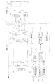
図2は、本発明による非接触電力伝送装置1の第1実施形態を示すブロック図である。
この図に示す通り、非接触電力伝送装置1は、固定部P1側(給電側)に設けられる構成と、可動部P2側(受電側)に設けられる構成とに大別される。給電側の構成は、上述した給電コイルL1に加えて、外部電源11、整流回路12、給電部13、測定部14、及び制御部15等からなる。これに対し、受電側の構成は、上述した受電コイルL2に加えて受電回路21等からなる。なお、受電側に設けられる負荷22は、非接触で伝送された電力が供給される負荷であり、例えば可動部P2に搭載された機器に内蔵されるモータ等である。
FIG. 2 is a block diagram showing a first embodiment of the non-contact
As shown in this figure, the non-contact
外部電源11は、可動部P2に伝送すべき電力を生成するために必要となる電力を供給する電源であり、例えば電圧が200[V]である三相交流電力を供給する電源である。なお、この外部電源11は、三相交流電源に限られることはなく、商用交流電源のような単相交流電力を供給する電源であっても良い。
整流回路12は、外部電源11から供給される交流電力を整流して直流電力に変換する回路であり、例えば図2に示す通り、三相全波整流回路(ブリッジ整流回路)で実現される。
The
The
外部電源11として燃料電池や太陽電池など直流電源を利用することも可能である。この場合、整流回路12は省略可能である。
A DC power source such as a fuel cell or a solar cell can be used as the
給電部13は、整流回路12から供給される電力を、給電コイルL1と可動部P2に設けられる受電コイルL2とによって形成される電磁気結合回路を介して非接触で可動部P2に供給する。具体的に、給電部13は、制御部15の制御の下で、整流回路12からの直流電力を交流電力に変換して給電コイルL1に与えることにより、可動部P2に対する非接触給電を実現する。
The
つまり、給電部13は、制御部15の制御によって、整流回路12からの直流電力を交流電力に変換する電力変換回路である。この給電部13は、例えば図2に示す通り、スイッチングレッグ13a,13b(直列接続された2つのトランジスタと、これら2つのトランジスタにそれぞれ並列接続されたダイオードとからなる回路)が並列接続された回路で実現される。なお、ここではトランジスタで代表させているが、パワーMOSFET(Metal Oxide Semiconductor Field Effect Transistor)やIGBT(Insulated Gate Bipolar Transistor)などの電力制御半導体素子でもよい。
That is, the
なお、給電部13と給電コイルL1との間には2つのコンデンサC1が設けられている。このコンデンサC1は、給電コイルL1とともに直列共振回路を形成する。給電コイルL1の一端は、一方のコンデンサC1を介して給電部13のスイッチングレッグ13aに接続されており、給電コイルL1の他端は、他方のコンデンサC1を介して給電部13のスイッチングレッグ13bに接続されている。
Two capacitors C1 are provided between the
測定部14は、3つの変位測定器14a〜14cを備えており、受電コイルL2の給電コイルL1に対する相対位置(相対的な位置及び姿勢の変位)を測定する。変位測定器14aは、上記の変位のうちのX方向における位置の変位(Xm)を測定する。変位測定器14bは、上記の変位のうちのY方向における位置の変位(Ym)を測定する。変位測定器14cは、上記の変位のうちのZ軸周りの回転方向における回転角の変位(θm)を測定する。変位測定器14a,14bとしては、例えば磁歪式リニアセンサ、マグネスケール、光の干渉パターンを用いて測長器等を用いることができる。また、変位測定器14cとしては、ロータリーエンコーダやレゾルバ等を使用することができる。
The
制御部15は、伝送電力選択器15a、発振回路15b、駆動クロック生成回路15c、及びドライバ制御回路15dを備え、測定部14で測定された前記相対位置に応じて金属部材Mに流れる誘導電流が小さくなるように前記電力を変化させるようになっている。
この例において、制御部15は、デューティテーブルT(後述する)に基づき、測定部14で測定された前記相対位置に応じて給電コイルL1と受電コイルL2間の電力のデューティDを変化させる。
なお「デューティD」とは、給電コイルL1から受電コイルL2へ伝送可能な最大電力に対する実際の伝送比率(%)を意味する。
The
In this example, the
“Duty D” means an actual transmission ratio (%) with respect to the maximum power that can be transmitted from the feeding coil L1 to the receiving coil L2.
伝送電力選択器15aは、金属部材Mに流れる誘導電流が小さくなるように前記相対位置に対応する電力のデューティDを記憶するデューティテーブルTを有し、測定部14の変位測定器14a〜14cからそれぞれ出力される変位(Xm,Ym,θm)の組み合わせによって受電コイルL2の給電コイルL1に対する相対位置を特定し、その相対位置における電力のデューティDを求めて出力する。
具体的に、伝送電力選択器15aは、デューティテーブルTを用いて、上記のデューティDを求める。なお、伝送電力選択器15aは、例えばCPU(中央処理装置)及びメモリ等を有するマイクロプロセッサと、伝送電力選択器15aの機能を実現するプログラムとの協働によって実現される。
The
Specifically, the
受電回路21は、受電コイルL2から供給される交流電力を整流して直流電力に変換する回路であり、例えば図2に示す通り、三相全波整流回路(ブリッジ整流回路)で実現される。
The
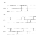
図3は、本発明の第1実施形態による給電部13の出力波形を示す図である。
この図において、(A)はデューティDが100%、(B)は同50%、(C)は同25%の場合であり、それぞれスイッチングレッグ13aの波形を示している。なお、スイッチングレッグ13bは上下反転した波形となる。
各図において、中心の水平線は上下のトランジスタが両方とも非導通の状態であり、上側の水平線は上のトランジスタが導通した状態、下側の水平線は下のトランジスタが導通した状態である。
図3(A)(B)(C)において、各波形の周期は同一であり、(A)は上下どちらかのトランジスタが常に導通しており、(B)は50%導通しており、(C)は25%導通している。
なおこの例において、デューティDは、スイッチングレッグ13a,13bのトランジスタが導通している時間の全体の時間に対する比率であり、周波数は変えていない。しかし、デューティDと併用して周波数を変化させてもよい。
上述した給電部13の出力波形を給電コイルL1から出力することにより、給電コイルL1と受電コイルL2間の伝送電力を制御することができる。
FIG. 3 is a diagram illustrating an output waveform of the
In this figure, (A) shows the case where the duty D is 100%, (B) shows the case where the duty D is 50%, and (C) shows the case where the duty D is 25%. The switching
In each figure, the central horizontal line is a state where both the upper and lower transistors are non-conductive, the upper horizontal line is a state where the upper transistor is conductive, and the lower horizontal line is a state where the lower transistor is conductive.
3A, 3B, and 3C, the period of each waveform is the same. In FIG. 3A, one of the upper and lower transistors is always conducting, and FIG. 3B is 50% conducting. C) is 25% conductive.
In this example, the duty D is the ratio of the time during which the transistors of the switching
By outputting the output waveform of the
図4は、デューティテーブルTの一例を示す図である。
この図に示す通り、デューティテーブルTは、固定部P1に対する可動部P2の相対的な位置及び姿勢の変位(Xm,Ym,θm)と、デューティDとの関係を示すテーブルである。このデューティテーブルTは、予め行われた実験やシミュレーションの結果に基づいて、給電コイルL1と受電コイルL2間に発生する電磁界と金属部材Mとの相対距離に応じて、予め設定されている。
FIG. 4 is a diagram illustrating an example of the duty table T. As illustrated in FIG.
As shown in this figure, the duty table T is a table showing the relationship between the relative position and orientation displacement (Xm, Ym, θm) of the movable part P2 with respect to the fixed part P1 and the duty D. This duty table T is set in advance according to the relative distance between the electromagnetic field generated between the feeding coil L1 and the receiving coil L2 and the metal member M based on the results of experiments and simulations performed in advance.
図4に示すデューティテーブルTは、固定部P1に対する可動部P2の相対的な位置及び姿勢の変位の取り得る値が、X方向については0〜100mmであり、Y方向については0〜50mmであり、Z軸周りの回転方向については0〜359°である場合のテーブルである。この図に示す通り、デューティテーブルTでは、変位(Xm,Ym,θm)の組み合わせ毎に、デューティDが規定されている。例えば、変位(Xm,Ym,θm)が(11mm,12mm,6°)である場合には、50%のデューティDが規定されている。 In the duty table T shown in FIG. 4, possible values of the relative position and posture displacement of the movable part P2 with respect to the fixed part P1 are 0 to 100 mm in the X direction and 0 to 50 mm in the Y direction. The rotation direction around the Z axis is a table in the case of 0 to 359 °. As shown in this figure, in the duty table T, a duty D is defined for each combination of displacements (Xm, Ym, θm). For example, when the displacement (Xm, Ym, θm) is (11 mm, 12 mm, 6 °), a duty D of 50% is defined.
ここで、図4に示すデューティテーブルTは、変位Xm,Ymについては1mm毎に規定され、変位θmについては1°毎に規定されているため、これら変位(Xm,Ym,θm)の組み合わせ数が膨大になり、デューティテーブルTを作成する手間がかかる。このような手間を軽減するために、変位(Xm,Ym,θm)の刻みが粗くされて、変位(Xm,Ym,θm)とデューティDとの関係が離散的に規定されたテーブルを作成して用いることもできる。例えば、変位Xm,Ymについては10mm毎に規定され、変位θmについては10°毎に規定されたものを用いることができる。この場合、10mmないし10°の刻みの中間の位置に対しては、10mm毎ないし10°毎に規定された値を線形補間等により補間してデューティDを求めることができる。 Here, since the duty table T shown in FIG. 4 is defined for each 1 mm for the displacements Xm and Ym and is defined for each 1 ° for the displacement θm, the number of combinations of these displacements (Xm, Ym, θm). Becomes enormous, and it takes time to create the duty table T. In order to reduce such labor, a table in which the increments of the displacement (Xm, Ym, θm) are coarsened and the relationship between the displacement (Xm, Ym, θm) and the duty D is discretely defined is created. Can also be used. For example, the displacements Xm and Ym can be defined every 10 mm, and the displacement θm can be defined every 10 °. In this case, the duty D can be obtained by interpolating a value defined every 10 mm to 10 ° by linear interpolation or the like for an intermediate position of 10 mm to 10 °.
図4に示すデューティテーブルTが用いられる場合には、伝送電力選択器15aは、デューティテーブルTを参照して、変位測定器14a〜14cからそれぞれ出力される変位(Xm,Ym,θm)の組み合わせに対応したデューティDを求める。即ち、伝送電力選択器15aは、デューティテーブルTの検索のみによってデューティDを求める。
When the duty table T shown in FIG. 4 is used, the
上述したデューティテーブルTのデューティDは、金属部材Mに流れる誘導電流が小さくなるように予め設定されている。すなわち、可動部P2の可動範囲内の位置に対して、給電コイルL1と受電コイルL2の間で非接触電力伝送する電磁界が金属部材Mに近いかどうかに応じて予めデューティテーブルTを作成しておく。 The duty D of the above-described duty table T is set in advance so that the induced current flowing through the metal member M becomes small. That is, a duty table T is created in advance according to whether or not the electromagnetic field for non-contact power transmission between the feeding coil L1 and the receiving coil L2 is close to the metal member M at a position within the movable range of the movable part P2. Keep it.
例えば、図1において、可動部P2が図中で左に寄っているときは、給電コイルL1から受電コイルL2へ非接触電力伝送する電磁界が金属部材Mに接近しているので、非接触電力伝送の電力を大きく低下させるため、スイッチングレッグ13a,13bの出力のデューティDを例えば25%にする。
また、可動部P2が左右の中間に位置しているときは、給電コイルL1から受電コイルL2へ非接触電力伝送する電磁界が金属部材Mに少し接近しているので、非接触電力伝送の電力を少し低下させ、スイッチングレッグ13a,13bの出力のデューティDを例えば50%にする。
さらに、可動部P2が右に寄っているときは、給電コイルL1から受電コイルL2へ非接触電力伝送する電磁界は金属部材Mから離れているので、非接触電力伝送の電力を低下させる必要がなく、スイッチングレッグ13a,13bの出力のデューティDを例えば100%にする。
なお、電力低下時のデューティDの値(25%,50%)は一例であり、金属部材Mの過熱を防止できれば異なる値でよい。
For example, in FIG. 1, when the movable part P2 is shifted to the left in the figure, the electromagnetic field for transmitting non-contact power from the feeding coil L1 to the receiving coil L2 is close to the metal member M, so that the non-contact power In order to greatly reduce the transmission power, the output duty D of the switching
Further, when the movable part P2 is located in the middle of the left and right, the electromagnetic field for transmitting non-contact power from the feeding coil L1 to the receiving coil L2 is slightly closer to the metal member M, so that the power of non-contact power transmission And the duty D of the output of the switching
Furthermore, when the movable part P2 is on the right, the electromagnetic field for transmitting non-contact power from the feeding coil L1 to the receiving coil L2 is away from the metal member M, so that it is necessary to reduce the power of non-contact power transmission. The output duty D of the switching
Note that the values (25%, 50%) of the duty D at the time of power reduction are merely examples, and different values may be used as long as the metal member M can be prevented from being overheated.
測定部14により受電コイルL2の給電コイルL1に対する相対位置を測定し、その相対位置における電磁界が金属部材Mに近いのであれば、デューティテーブルTに基づき非接触電力伝送の電力のデューティDを低下させる。
従って、この構成より、金属部材Mの過熱が抑制され、金属部材Mに取り付けられている装置や部品の動作不良や故障を防止し、かつエネルギーの無駄を低減することができる。
If the relative position of the power receiving coil L2 with respect to the power feeding coil L1 is measured by the measuring
Therefore, with this configuration, overheating of the metal member M is suppressed, malfunctions and failures of devices and parts attached to the metal member M can be prevented, and energy waste can be reduced.
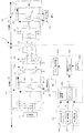
図5は、本発明による非接触電力伝送装置1の第2実施形態を示すブロック図である。
この例において、本発明の非接触電力伝送装置1は、給電電力測定回路26と受電電力測定回路30とを備える。
給電電力測定回路26は、給電側母線間の電圧V1(t)を測定する電圧測定器27、給電側母線の電流I1(t)を測定する電流測定器28、及び電圧V1(t)と電流I1(t)から給電側の電力P1(=V1(t)×I1(t))を演算する電力量演算器29を有し、給電コイルL1から給電される給電電力P1を測定する。
受電電力測定回路30は、受電側母線間の電圧V2(t)を測定する電圧測定器31、受電側母線の電流I2(t)を測定する電流測定器32、及び電圧V2(t)と電流I2(t)から受電側の電力P2(=V2(t)×I2(t))を演算する電力量演算器33を有し、受電コイルL2から受電される受電電力P2を測定する。
受電電力P2は、図示しない無線通信装置を介して給電側に送信されるのがよい。
デューティテーブルTは、受電コイルL2の給電コイルL1に対する相対位置における電力の伝送効率に応じて設定される。
FIG. 5 is a block diagram showing a second embodiment of the non-contact
In this example, the non-contact
The feeding
The received
The received power P2 is preferably transmitted to the power feeding side via a wireless communication device (not shown).
The duty table T is set according to the power transmission efficiency at a relative position of the power receiving coil L2 with respect to the power feeding coil L1.
電磁界は目に見えないため、可動部P2のそれぞれの位置において電磁界が金属部材Mに近いかどうかを判断することが難しい。
従って、この実施形態では、給電電力測定回路26と受電電力測定回路30により受電電力P2の給電電力P1に対する伝送効率(P2/P1)を測定しながら可動部P2を移動可能な範囲全体にわたって動かす。それぞれの受電コイルL2の給電コイルL1に対する相対位置において伝送効率を計算し、伝送効率が低い位置を、電力のデューティDを低下させる位置としてデューティテーブルTに記憶させる。
Since the electromagnetic field is invisible, it is difficult to determine whether the electromagnetic field is close to the metal member M at each position of the movable part P2.
Therefore, in this embodiment, the movable part P2 is moved over the entire movable range while measuring the transmission efficiency (P2 / P1) of the received power P2 with respect to the supplied power P1 by the supplied
図5の実施形態において、可動部P2の位置を、X,Y,θ方向に一定ずつ移動させ、それぞれの位置で伝送効率を実測し、それぞれの位置におけるデューティDを例えば以下のように決める。
伝送効率80%以上(金属部材Mから離れている場合に相当):デューティD=100%
伝送効率80%未満60%以上(金属部材Mにある程度近い場合に相当):デューティD=50%
伝送効率60%未満(金属部材Mに近い):デューティD=25%
移動可能な範囲内で、X,Y,θを一定間隔(デューティテーブルTのメッシュと同じ間隔)で動かしてデューティテーブルTの内容を埋めて、デューティテーブルTに記憶させる。
なお、以上の数値は一例であり、本発明の効果が得られるのであれば他の数値であってもよい。
In the embodiment of FIG. 5, the position of the movable part P2 is moved in the X, Y, and θ directions at regular intervals, the transmission efficiency is measured at each position, and the duty D at each position is determined as follows, for example.
Transmission efficiency of 80% or more (corresponding to the case where the metal member M is separated): Duty D = 100%
Transmission efficiency less than 80% and 60% or more (corresponding to a case close to metal member M to some extent): Duty D = 50%
Transmission efficiency less than 60% (close to metal member M): Duty D = 25%
Within the movable range, X, Y, and θ are moved at a constant interval (the same interval as the mesh of the duty table T) to fill the contents of the duty table T and store them in the duty table T.
The above numerical values are examples, and other numerical values may be used as long as the effects of the present invention can be obtained.
なお機器の寸法、構成、配置が変わらなければデューティテーブルTの内容を変える必要はないので、給電電力測定回路26と受電電力測定回路30はデューティテーブルTの内容を作成した後で取り外してもよい。
また、図5の構成を保ったままとし、機器の寸法、構成、配置が変化した場合には同じ操作により再度デューティテーブルTの内容を更新してもよい。
Since the contents of the duty table T do not need to be changed unless the dimensions, configuration, and arrangement of the device are changed, the feeding
5 may be maintained, and the contents of the duty table T may be updated again by the same operation when the dimensions, configuration, and arrangement of the device change.
上述した構成により、電磁界分布をシミュレーション等で正確に求めたり、測定器で測定する必要なしに、同一の効果が得られる。 With the configuration described above, the same effect can be obtained without the need to accurately determine the electromagnetic field distribution by simulation or the like or to measure it with a measuring instrument.
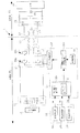
図6は、本発明による非接触電力伝送装置1の第3実施形態を示すブロック図である。
この例では、受電側に電力蓄積要素34を備える。
伝送電力を低下させている位置(デューティDが小さい位置)で負荷22への電力供給が不足する可能性がある場合、電力蓄積要素34(リチウムイオン電池やニッケル水素電池などの2次電池、電気二重層キャパシタ、電解コンデンサ、など)を受電側に付加し、伝送電力を低下させない位置(デューティDが大きい位置)で電力を電力蓄積要素34に蓄積しておき、伝送電力を低下させる位置では電力蓄積要素34から放電させて負荷22への電力供給を補うようになっている。
その他の構成は、第1実施形態と同様である。
FIG. 6 is a block diagram showing a third embodiment of the non-contact
In this example, the
When there is a possibility that power supply to the
Other configurations are the same as those of the first embodiment.
上述した本発明の装置と方法によれば、制御部15が、測定部14で測定された相対位置に応じて金属部材Mに流れる誘導電流が小さくなるように電力を変化させるので、受電コイルL1と給電コイルL2の相対的な位置関係が変化し金属部材Mに近づいても、金属部材Mに流れる誘導電流が小さくなるので、金属部材Mの過熱を抑制することができる。
According to the apparatus and method of the present invention described above, the
なお、本発明は上述した実施形態に限定されず、特許請求の範囲の記載によって示され、さらに特許請求の範囲の記載と均等の意味および範囲内でのすべての変更を含むものである。 In addition, this invention is not limited to embodiment mentioned above, is shown by description of a claim, and also includes all the changes within the meaning and range equivalent to description of a claim.
例えば実施例において給電コイルL1及び受電コイルL2の平面視形状を共に長方形形状としたが、非接触電力伝送が可能であればコイルの形状は円形、楕円形状等任意である。給電コイルL1と受電コイルL2の形状が異なっていてもよい。 For example, in the embodiment, the planar view shapes of the feeding coil L1 and the receiving coil L2 are both rectangular, but the shape of the coil is arbitrary, such as circular or elliptical, as long as non-contact power transmission is possible. The shapes of the feeding coil L1 and the receiving coil L2 may be different.
1 非接触電力伝送装置、11 外部電源、12 整流回路、
13 給電部、13a,13b スイッチングレッグ、
14 測定部、14a〜14c 変位測定器、
15 制御部、15a 伝送電力選択器、15b 発振回路、
15c 駆動クロック生成回路、15d ドライバ制御回路、
21 受電回路、22 負荷、26 給電電力測定回路、
27 電圧測定器、28 電流測定器、29 電力量演算器、
30 受電電力測定回路、31 電圧測定器、
32 電流測定器、33 電力量演算器、34 電力蓄積要素、
L1 給電コイル、L2 受電コイル、
P1 固定部、P2 可動部、M 金属部材、
D デューティ、T デューティテーブル
1 contactless power transmission device, 11 external power supply, 12 rectifier circuit,
13 Power feeding part, 13a, 13b Switching leg,
14 measurement part, 14a-14c displacement measuring instrument,
15 control unit, 15a transmission power selector, 15b oscillation circuit,
15c drive clock generation circuit, 15d driver control circuit,
21 power receiving circuit, 22 load, 26 power feeding power measuring circuit,
27 Voltage measuring device, 28 Current measuring device, 29 Electric energy calculator,
30 Received power measurement circuit, 31 Voltage measuring device,
32 current measuring device, 33 electric energy calculator, 34 power storage element,
L1 feeding coil, L2 receiving coil,
P1 fixed part, P2 movable part, M metal member,
D duty, T duty table
Claims (6)
前記給電コイルに前記電力を供給する給電部と、
受電コイルの給電コイルに対する相対位置を測定する測定部と、
前記給電部を制御する制御部とを備え、
制御部は、測定部で測定された前記相対位置に応じて金属部材に流れる誘導電流が小さくなるように前記電力を変化させる、ことを特徴とする非接触電力伝送装置。 A non-contact power transmission device that transmits power in a non-contact manner between a feeding coil and a receiving coil,
A power supply unit for supplying the power to the power supply coil;
A measurement unit for measuring a relative position of the power receiving coil with respect to the power supply coil;
A control unit for controlling the power feeding unit,
The control unit changes the power so that an induced current flowing through the metal member is reduced according to the relative position measured by the measurement unit, and the contactless power transmission device according to claim 1.
前記受電コイルから受電される受電電力を測定する受電電力測定回路とを備え、
前記デューティテーブルは、前記相対位置における前記電力の伝送効率に応じて設定される、ことを特徴とする請求項2記載の非接触電力伝送装置。 A feeding power measuring circuit for measuring feeding power fed from the feeding coil;
A received power measuring circuit for measuring received power received from the receiving coil,
The contactless power transmission device according to claim 2, wherein the duty table is set according to a transmission efficiency of the power at the relative position.
給電部により、前記給電コイルに前記電力を供給し、
測定部により、受電コイルの給電コイルに対する相対位置を測定し、
制御部により、測定部で測定された前記相対位置に応じて金属部材に流れる誘導電流が小さくなるように前記電力を変化させる、ことを特徴とする非接触電力伝送方法。 A non-contact power transmission method for non-contact transmission of power between a feeding coil and a receiving coil,
The power supply unit supplies the power to the power supply coil,
With the measurement unit, measure the relative position of the receiving coil to the feeding coil,
A non-contact power transmission method characterized in that the control unit changes the power so that an induced current flowing in the metal member is reduced according to the relative position measured by the measurement unit.
Priority Applications (5)
| Application Number | Priority Date | Filing Date | Title |
|---|---|---|---|
| JP2012069247A JP5885074B2 (en) | 2012-03-26 | 2012-03-26 | Non-contact power transmission apparatus and method |
| CN201380015178.7A CN104247208B (en) | 2012-03-26 | 2013-03-19 | Non-contact power transmission device and method |
| EP13769917.9A EP2833514B1 (en) | 2012-03-26 | 2013-03-19 | Non-contact power transmission apparatus and non-contact power transmission method |
| PCT/JP2013/057788 WO2013146456A1 (en) | 2012-03-26 | 2013-03-19 | Non-contact power transmission apparatus and non-contact power transmission method |
| US14/488,784 US9866059B2 (en) | 2012-03-26 | 2014-09-17 | Wireless power transmission device and wireless power transmission method |
Applications Claiming Priority (1)
| Application Number | Priority Date | Filing Date | Title |
|---|---|---|---|
| JP2012069247A JP5885074B2 (en) | 2012-03-26 | 2012-03-26 | Non-contact power transmission apparatus and method |
Publications (2)
| Publication Number | Publication Date |
|---|---|
| JP2013201848A true JP2013201848A (en) | 2013-10-03 |
| JP5885074B2 JP5885074B2 (en) | 2016-03-15 |
Family
ID=49259713
Family Applications (1)
| Application Number | Title | Priority Date | Filing Date |
|---|---|---|---|
| JP2012069247A Expired - Fee Related JP5885074B2 (en) | 2012-03-26 | 2012-03-26 | Non-contact power transmission apparatus and method |
Country Status (5)
| Country | Link |
|---|---|
| US (1) | US9866059B2 (en) |
| EP (1) | EP2833514B1 (en) |
| JP (1) | JP5885074B2 (en) |
| CN (1) | CN104247208B (en) |
| WO (1) | WO2013146456A1 (en) |
Cited By (1)
| Publication number | Priority date | Publication date | Assignee | Title |
|---|---|---|---|---|
| JP2015128370A (en) * | 2013-11-28 | 2015-07-09 | Tdk株式会社 | Wireless power transmission system |
Families Citing this family (9)
| Publication number | Priority date | Publication date | Assignee | Title |
|---|---|---|---|---|
| JP6467358B2 (en) * | 2016-02-01 | 2019-02-13 | 株式会社日立製作所 | Non-contact power feeding device and elevator |
| KR20170111393A (en) * | 2016-03-28 | 2017-10-12 | 엘지이노텍 주식회사 | Apparatus for Transferring Wireless Power and Method for Controlling Power of The Same |
| EP4418494A3 (en) * | 2016-04-20 | 2025-01-15 | Yamaha Hatsudoki Kabushiki Kaisha | Wireless power supply device |
| EP3535547A4 (en) * | 2016-11-02 | 2020-06-10 | KSR IP Holdings LLC | KEY RATIO MODULATION FOR INDUCTIVE SENSORS |
| WO2019089073A1 (en) | 2017-11-02 | 2019-05-09 | Ksr Ip Holdings Llc. | Duty cycle for inductive position sensors |
| CN112769253B (en) * | 2019-11-04 | 2023-12-26 | 北京小米移动软件有限公司 | Wireless charging method, device, wireless charging transmitter and storage medium |
| FR3107791B1 (en) * | 2020-03-02 | 2023-03-24 | Radiall Sa | Wireless and contactless electrical energy transfer assembly comprising an improved system for regulating the energy transferred. |
| CN111917164A (en) * | 2020-07-09 | 2020-11-10 | 中国电力科学研究院有限公司 | Wireless charging system applied to transformer substation inspection robot |
| JP2022153688A (en) * | 2021-03-30 | 2022-10-13 | ラピステクノロジー株式会社 | Contactless power supply device, power receiving device, and power transmission device |
Citations (3)
| Publication number | Priority date | Publication date | Assignee | Title |
|---|---|---|---|---|
| JPH11122832A (en) * | 1997-10-07 | 1999-04-30 | Casio Comput Co Ltd | Charging device |
| JP2008295274A (en) * | 2007-05-28 | 2008-12-04 | Sony Ericsson Mobilecommunications Japan Inc | Non-contact power transmission coil unit, portable terminal, power transmission device, and non-contact power transmission system |
| JP2010119251A (en) * | 2008-11-14 | 2010-05-27 | Toko Inc | Contactless power transmission system |
Family Cites Families (21)
| Publication number | Priority date | Publication date | Assignee | Title |
|---|---|---|---|---|
| JPH0851137A (en) | 1994-08-08 | 1996-02-20 | Shinko Electric Co Ltd | Transport equipment in semiconductor manufacturing equipment |
| JP4200257B2 (en) | 2000-09-26 | 2008-12-24 | パナソニック電工株式会社 | Non-contact power transmission device |
| US9129741B2 (en) | 2006-09-14 | 2015-09-08 | Qualcomm Incorporated | Method and apparatus for wireless power transmission |
| JP4649430B2 (en) | 2007-03-20 | 2011-03-09 | セイコーエプソン株式会社 | Non-contact power transmission device |
| JP4561786B2 (en) | 2007-07-13 | 2010-10-13 | セイコーエプソン株式会社 | Power transmission device and electronic device |
| JP2009089463A (en) * | 2007-09-27 | 2009-04-23 | Panasonic Corp | Electronic equipment and charging system |
| JP2009225551A (en) | 2008-03-14 | 2009-10-01 | Bridgestone Corp | Electric power transmission system |
| JP5359184B2 (en) | 2008-10-22 | 2013-12-04 | トヨタ自動車株式会社 | Power supply system |
| JP4759610B2 (en) | 2008-12-01 | 2011-08-31 | 株式会社豊田自動織機 | Non-contact power transmission device |
| JP5515659B2 (en) | 2008-12-01 | 2014-06-11 | 株式会社豊田自動織機 | Non-contact power transmission device |
| JP5114371B2 (en) | 2008-12-09 | 2013-01-09 | 株式会社豊田自動織機 | Non-contact power transmission device |
| JP5114372B2 (en) | 2008-12-09 | 2013-01-09 | 株式会社豊田自動織機 | Power transmission method and non-contact power transmission apparatus in non-contact power transmission apparatus |
| JP5349069B2 (en) | 2009-02-09 | 2013-11-20 | 株式会社豊田自動織機 | Non-contact power transmission device |
| EP2416470B1 (en) | 2009-03-30 | 2019-11-13 | Fujitsu Limited | Wireless power supply system, wireless power transmission device, and wireless power receiving device |
| JP5365306B2 (en) | 2009-03-31 | 2013-12-11 | 富士通株式会社 | Wireless power supply system |
| CA2757623A1 (en) * | 2009-04-08 | 2010-10-14 | Access Business Group International Llc | Selectable coil array |
| JP5603647B2 (en) * | 2009-05-13 | 2014-10-08 | キヤノン株式会社 | Power feeding device, power feeding device control method, and power feeding communication system |
| JP5389735B2 (en) * | 2010-02-08 | 2014-01-15 | 昭和飛行機工業株式会社 | Power transmission instruction transmission device |
| TWI577103B (en) * | 2010-02-08 | 2017-04-01 | 通路實業集團國際公司 | Implanted parasitic metal detection and related methods |
| CN102195366B (en) * | 2010-03-19 | 2014-03-12 | Tdk株式会社 | Wireless power feeder, and wireless power transmission system |
| US20130082536A1 (en) * | 2011-03-22 | 2013-04-04 | Access Business Group International Llc | System and method for improved control in wireless power supply systems |
-
2012
- 2012-03-26 JP JP2012069247A patent/JP5885074B2/en not_active Expired - Fee Related
-
2013
- 2013-03-19 WO PCT/JP2013/057788 patent/WO2013146456A1/en not_active Ceased
- 2013-03-19 CN CN201380015178.7A patent/CN104247208B/en active Active
- 2013-03-19 EP EP13769917.9A patent/EP2833514B1/en active Active
-
2014
- 2014-09-17 US US14/488,784 patent/US9866059B2/en active Active
Patent Citations (3)
| Publication number | Priority date | Publication date | Assignee | Title |
|---|---|---|---|---|
| JPH11122832A (en) * | 1997-10-07 | 1999-04-30 | Casio Comput Co Ltd | Charging device |
| JP2008295274A (en) * | 2007-05-28 | 2008-12-04 | Sony Ericsson Mobilecommunications Japan Inc | Non-contact power transmission coil unit, portable terminal, power transmission device, and non-contact power transmission system |
| JP2010119251A (en) * | 2008-11-14 | 2010-05-27 | Toko Inc | Contactless power transmission system |
Cited By (1)
| Publication number | Priority date | Publication date | Assignee | Title |
|---|---|---|---|---|
| JP2015128370A (en) * | 2013-11-28 | 2015-07-09 | Tdk株式会社 | Wireless power transmission system |
Also Published As
| Publication number | Publication date |
|---|---|
| US20150001960A1 (en) | 2015-01-01 |
| JP5885074B2 (en) | 2016-03-15 |
| US9866059B2 (en) | 2018-01-09 |
| EP2833514B1 (en) | 2018-07-11 |
| WO2013146456A1 (en) | 2013-10-03 |
| CN104247208A (en) | 2014-12-24 |
| CN104247208B (en) | 2018-09-11 |
| EP2833514A1 (en) | 2015-02-04 |
| EP2833514A4 (en) | 2015-11-11 |
Similar Documents
| Publication | Publication Date | Title |
|---|---|---|
| JP5885074B2 (en) | Non-contact power transmission apparatus and method | |
| WO2013081045A1 (en) | Device and method for contactless power transfer | |
| US9941744B2 (en) | Non-contact power supply circuit | |
| JP6406225B2 (en) | Non-contact power feeding device | |
| CN202444300U (en) | Wireless charging device | |
| JP6551853B2 (en) | Power transmission device, vehicle equipped with power transmission device and wireless power transmission system | |
| Cai et al. | Robust wide-area wireless charging of multipath movable receivers: A coupling mechanism and simplified configuration strategy | |
| JPWO2014199691A1 (en) | Power feeding device and non-contact power feeding system | |
| Kazmierkowski et al. | Inductive coupled contactless energy transfer systems-a review | |
| CN106026417B (en) | The wireless energy transfer system and its control method of leggy excitation-total space pickup | |
| JP2018113765A (en) | Power transmission system and power transmission sheet | |
| CN205353630U (en) | Servo drive control integrated device | |
| JP5605301B2 (en) | Contactless power supply system | |
| JP2011234051A (en) | Power line communication system | |
| Li et al. | A multi‐receiver adaptive design of variable magnetic coupled structure for omnidirectional WPT system | |
| Wu et al. | Investigation of a GaN-based bidirectional wireless power converter using resonant inductive coupling | |
| Ong et al. | Analysis of impedance matched circuit for wireless power transfer | |
| US12038733B2 (en) | Automation system | |
| EP3435519B1 (en) | Wireless power supply device | |
| JP2013219971A (en) | Power supply system for houses | |
| JP6579009B2 (en) | Wireless power transmission system | |
| Wang et al. | A pulse energy injection inverter for the switch-mode inductive power transfer system | |
| CN106842990A (en) | A kind of servo drive control integrated apparatus | |
| Ekpa | Design and analysis of wireless nanogrid for non-smartphones | |
| Smirnov | Wireless Power Transmission System Based |
Legal Events
| Date | Code | Title | Description |
|---|---|---|---|
| A621 | Written request for application examination |
Free format text: JAPANESE INTERMEDIATE CODE: A621 Effective date: 20150127 |
|
| A131 | Notification of reasons for refusal |
Free format text: JAPANESE INTERMEDIATE CODE: A131 Effective date: 20150909 |
|
| A521 | Request for written amendment filed |
Free format text: JAPANESE INTERMEDIATE CODE: A523 Effective date: 20151014 |
|
| TRDD | Decision of grant or rejection written | ||
| A01 | Written decision to grant a patent or to grant a registration (utility model) |
Free format text: JAPANESE INTERMEDIATE CODE: A01 Effective date: 20160115 |
|
| A61 | First payment of annual fees (during grant procedure) |
Free format text: JAPANESE INTERMEDIATE CODE: A61 Effective date: 20160128 |
|
| R151 | Written notification of patent or utility model registration |
Ref document number: 5885074 Country of ref document: JP Free format text: JAPANESE INTERMEDIATE CODE: R151 |
|
| R250 | Receipt of annual fees |
Free format text: JAPANESE INTERMEDIATE CODE: R250 |
|
| R250 | Receipt of annual fees |
Free format text: JAPANESE INTERMEDIATE CODE: R250 |
|
| LAPS | Cancellation because of no payment of annual fees |