JP2013181594A - Rotary damper - Google Patents

Rotary damper Download PDF

Info

Publication number
JP2013181594A
JP2013181594A JP2012045036A JP2012045036A JP2013181594A JP 2013181594 A JP2013181594 A JP 2013181594A JP 2012045036 A JP2012045036 A JP 2012045036A JP 2012045036 A JP2012045036 A JP 2012045036A JP 2013181594 A JP2013181594 A JP 2013181594A
Authority
JP
Japan
Prior art keywords
shaft
chamber
vane
case
rotary damper
Prior art date
Legal status (The legal status is an assumption and is not a legal conclusion. Google has not performed a legal analysis and makes no representation as to the accuracy of the status listed.)
Pending
Application number
JP2012045036A
Other languages
Japanese (ja)
Inventor
Atsushi Sakuta
敦 作田
Takahiro Kondo
卓宏 近藤
Current Assignee (The listed assignees may be inaccurate. Google has not performed a legal analysis and makes no representation or warranty as to the accuracy of the list.)
KYB Corp
Original Assignee
KYB Corp
Priority date (The priority date is an assumption and is not a legal conclusion. Google has not performed a legal analysis and makes no representation as to the accuracy of the date listed.)
Filing date
Publication date
Application filed by KYB Corp filed Critical KYB Corp
Priority to JP2012045036A priority Critical patent/JP2013181594A/en
Publication of JP2013181594A publication Critical patent/JP2013181594A/en
Pending legal-status Critical Current

Links

Images

Landscapes

  • Fluid-Damping Devices (AREA)

Abstract

PROBLEM TO BE SOLVED: To provide a rotary damper that can exhibit an aimed damping force, even when a pressure in an operation room has become high.SOLUTION: A rotary damper D includes: a shaft 1; a pair of side panels 2, 3 axially supporting the shaft 1 while allowing the rotation in a circumferential direction; a case 4 provided between the side panels 2 and 3 and forming an operation room R inside; and a vane 5 provided in the shaft 1 having a tip end in sliding contact with an inner circumference of the case 4 and partitioning the operation room R to one side room R1 and the other side room R2. In the damper, there is provided a pressing member P for pressing each side panels 2, 3 toward the vane 5.

Description

本発明は、ロータリダンパの改良に関する。   The present invention relates to an improvement of a rotary damper.

従来、ロータリダンパにあっては、シャフトと、上記シャフトを周方向への回転を許容しつつ軸支する一対のサイドパネルと、これらのサイドパネルで挟持されて内部に作動室を形成するケースと、上記シャフトに設けられて上記作動室を一方室と他方室とに区画するベーンとを備えて構成されている。   Conventionally, in a rotary damper, a shaft, a pair of side panels that pivotally support the shaft while allowing rotation in the circumferential direction, and a case that is sandwiched between these side panels to form a working chamber inside. The vane is provided on the shaft and divides the working chamber into one chamber and the other chamber.

そして、ロータリダンパは、たとえば、シャフトに外部から回転力が加わると、シャフトの回転に伴ってベーンが作動室内で移動して一方室を縮小し、他方室を拡大するよう動作し、縮小される一方室から拡大される他方室へ移動する油の流れに減衰弁で抵抗を与えることで、シャフトの回転を抑制する減衰力を発揮するようになっている(特許文献1参照)。   Then, for example, when a rotational force is applied to the shaft from the outside, the rotary damper operates to reduce the one chamber while the vane moves in the working chamber as the shaft rotates, and to reduce the other chamber. A damping force that suppresses the rotation of the shaft is exhibited by applying resistance to the flow of oil moving from the one chamber to the other chamber with a damping valve (see Patent Document 1).

特開平8−177928号公報JP-A-8-177828

このようなロータリダンパを車両のサスペンションに組み込んで使用する場合を考えると、たとえば、ロータリダンパのケースを車体へ固定し、ロータリダンパのシャフトを車体に揺動可能に取り付けられて車輪を保持するサスペンションアームに連結することにより、ロータリダンパをサスペンションへ組み込むことになる。より具体的には、シャフトの回転方向をサスペンションアームの揺動方向に一致させて、シャフトとサスペンションアームとを連結することになる。   Considering the case where such a rotary damper is incorporated into a vehicle suspension, for example, the rotary damper case is fixed to the vehicle body, and the rotary damper shaft is swingably attached to the vehicle body to hold the wheel. By connecting to the arm, the rotary damper is incorporated into the suspension. More specifically, the shaft and the suspension arm are connected with the rotation direction of the shaft coincident with the swinging direction of the suspension arm.

ここで、特に、四輪車のサスペンションにロータリダンパを用いる場合、重い車体の振動を減衰させるために大きな減衰力を発生する必要があり、作動室内の圧力が非常に高くなる。作動室内が非常に高圧となると、ケースを挟持するサイドパネルが作動室内の内圧で撓み、ベーンとサイドパネルとの間に隙間が生じて、一方室と他方室とが当該隙間を介して連通してしまう。   Here, in particular, when a rotary damper is used for a suspension of a four-wheel vehicle, it is necessary to generate a large damping force in order to attenuate the vibration of the heavy vehicle body, and the pressure in the working chamber becomes very high. When the working chamber becomes extremely high in pressure, the side panel holding the case is bent by the internal pressure in the working chamber, a gap is created between the vane and the side panel, and the one chamber communicates with the other chamber through the gap. End up.

すると、作動室内の油が減衰弁を迂回して隙間をも介して一方室と他方室とを行き来することが可能なって、狙り通りの減衰力を発揮できなくなる可能性がある。   Then, the oil in the working chamber can bypass the damping valve and go back and forth between the one chamber and the other chamber via the gap, and the damping force as intended may not be exhibited.

そこで、本発明は、上記した不具合を改善するために創案されたものであって、その目的とするところは、作動室内が高圧となっても狙い通りの減衰力を発揮することができるロータリダンパを提供することである。   Accordingly, the present invention has been developed to improve the above-described problems, and the object of the present invention is to provide a rotary damper that can exhibit a desired damping force even when the working chamber has a high pressure. Is to provide.

上記した課題を解決するために、本発明の課題解決手段は、シャフトと、上記シャフトを周方向への回転を許容しつつ軸支する一対のサイドパネルと、これらのサイドパネル間に設けられて内部に作動室を形成するケースと、上記シャフトに設けられて先端が上記ケースの内周に摺接して上記作動室を一方室と他方室とに区画するベーンとを備えたロータリダンパにおいて、上記各サイドパネルをベーン側へ向けて押圧する押圧部材を備えたことを特徴とする。   In order to solve the above-described problems, the problem-solving means of the present invention is provided between a shaft, a pair of side panels that pivotally support the shaft while allowing the shaft to rotate in the circumferential direction, and the side panels. In a rotary damper comprising: a case that forms a working chamber therein; and a vane that is provided on the shaft and has a tip that slides into the inner periphery of the case and divides the working chamber into one chamber and the other chamber. A pressing member that presses each side panel toward the vane side is provided.

この押圧部材によって、サイドパネルがベーン側へ向けて押圧されるので、作動室内の圧力が高圧となっても、サイドパネルとベーンとが接触状態に保たれ、一方室と他方室とがベーン周りを介して連通することがなくなる。   Since the side panel is pressed toward the vane by the pressing member, the side panel and the vane are kept in contact with each other even if the pressure in the working chamber becomes high, and the one chamber and the other chamber are around the vane. It will not be possible to communicate via.

本発明のロータリダンパによれば、作動室内が高圧となっても狙い通りの減衰力を発揮することができる。   According to the rotary damper of the present invention, a desired damping force can be exhibited even when the working chamber is at a high pressure.

一実施の形態におけるロータリダンパの縦断面図である。It is a longitudinal cross-sectional view of the rotary damper in one embodiment. 一実施の形態におけるロータリダンパの横断面図である。It is a cross-sectional view of the rotary damper in one embodiment.

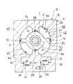
以下、図に示した実施の形態に基づき、本発明を説明する。図1および図2に示すように、一実施の形態におけるロータリダンパDは、シャフト1と、上記シャフト1を周方向への回転を許容しつつ軸支する一対のサイドパネル2,3と、これらのサイドパネル2,3間に設けられて内部に作動室Rを形成するケース4と、上記シャフト1に設けられて先端が上記ケース4の内周に摺接して上記作動室Rを一方室R1と他方室R2とに区画するベーン5と、各サイドパネル2,3をベーン5側へ向けて押圧する押圧部材Pとを備えて構成されている。そして、このロータリダンパDは、シャフト1をケース4に対して周方向へ回転させると、このシャフト1の回転を抑制する減衰力を発揮する。   The present invention will be described below based on the embodiments shown in the drawings. As shown in FIGS. 1 and 2, the rotary damper D in one embodiment includes a shaft 1, a pair of side panels 2 and 3 that support the shaft 1 while allowing the shaft 1 to rotate in the circumferential direction, and these A case 4 provided between the side panels 2 and 3 and forming a working chamber R therein, and a tip 1 provided on the shaft 1 and slidingly contacting the inner periphery of the case 4 to connect the working chamber R to the one chamber R1. And the other chamber R2 and a pressing member P that presses the side panels 2 and 3 toward the vane 5 side. The rotary damper D exhibits a damping force that suppresses the rotation of the shaft 1 when the shaft 1 is rotated in the circumferential direction with respect to the case 4.

以下、このロータリダンパDの各部について詳細に説明する。まず、シャフト1は、筒状であって、図1中上端である一端外周に設けられて図示しない車両のサスペンションアームに連結されるアームAの固定を可能とするセレーション1aと、中間に設けられて図1中上端および下端よりも大径な拡径部1bと、当該拡径部1bの外周であって周方向に180度の位相をもって設けた一対のベーン5,5とを備えている。なお、上記したところでは、図外の継手等への連結のためにセレーション1aを設けているが、接続方法はこれに限定されない。   Hereinafter, each part of the rotary damper D will be described in detail. First, the shaft 1 has a cylindrical shape and is provided in the middle of a serration 1a that is provided on the outer periphery of one end, which is the upper end in FIG. 1, and that can fix an arm A that is connected to a suspension arm of a vehicle (not shown). 1 includes an enlarged diameter portion 1b having a diameter larger than that of the upper end and the lower end, and a pair of vanes 5 and 5 provided on the outer circumference of the enlarged diameter portion 1b and having a phase of 180 degrees in the circumferential direction. In addition, in the place mentioned above, although the serration 1a is provided for the coupling | bonding to the coupling etc. outside a figure, the connection method is not limited to this.

アームAは、図1に示すように、シャフト1のセレーション1aの外周に装着される環状の装着部a1と、装着部a1から伸びて図外のサスペンションアームに連結されるロッド状のアーム部a2とを備えており、シャフト1の図1中上端内周に螺着される筒状ボルトBによってシャフト1に回転不能に連結されている。   As shown in FIG. 1, the arm A includes an annular mounting portion a1 that is mounted on the outer periphery of the serration 1a of the shaft 1, and a rod-shaped arm portion a2 that extends from the mounting portion a1 and is connected to a suspension arm that is not shown. And is non-rotatably connected to the shaft 1 by a cylindrical bolt B screwed to the inner periphery of the upper end of the shaft 1 in FIG.

サイドパネル2は、この実施の形態の場合、筒状でシャフト1の図1中上端が挿通されるシャフト挿通部2aと、このシャフト挿通部2aの図1中下端外周に設けられてケース4にプレート6を介して積層されるフランジ状のキャップ部2bと、キャップ部2bに同一円周上に間隔を開けて設けた複数のボルト挿通孔2cとを備えている。   In the case of this embodiment, the side panel 2 has a cylindrical shape, a shaft insertion portion 2a through which the upper end of the shaft 1 in FIG. 1 is inserted, and an outer periphery of the lower end of the shaft insertion portion 2a in FIG. A flange-shaped cap portion 2b stacked via the plate 6 and a plurality of bolt insertion holes 2c provided on the cap portion 2b at intervals on the same circumference are provided.

シャフト挿通部2aの内周には、シャフト1の図1中上方側に摺接する筒状のベアリング11が装着され、同じくシャフト挿通部2aの内周であって、このベアリング11よりも図1中上方となる反ケース4側にはシャフト1の外周に摺接する環状のUパッキン13と環状のダストシール14とがそれぞれ装着されている。Uパッキン13は、シャフト1の外周に密着してシャフト1とサイドパネル2との間をシールし、図1中最上方となる最外方に設けたダストシール14は、シャフト1とサイドパネル2との間へ外方からの塵や埃の侵入を防止している。さらに、キャップ部2bのケース4側には、Oリング15が装着されており、このOリング15は、サイドパネル2とプレート6との間をシールしている。   A cylindrical bearing 11 that is in sliding contact with the upper side of the shaft 1 in FIG. 1 is attached to the inner periphery of the shaft insertion portion 2a, and is also the inner periphery of the shaft insertion portion 2a. An annular U-packing 13 and an annular dust seal 14 that are in sliding contact with the outer periphery of the shaft 1 are respectively mounted on the opposite side of the case 4. The U packing 13 is in close contact with the outer periphery of the shaft 1 and seals between the shaft 1 and the side panel 2. The dust seal 14 provided at the outermost position in FIG. Prevents dust and dirt from entering between. Furthermore, an O-ring 15 is mounted on the case 4 side of the cap portion 2b, and this O-ring 15 seals between the side panel 2 and the plate 6.

また、シャフト挿通部2aには、図1に示すように、開口2dが設けられており、この開口2dにはシャフト挿通部2a内に収容されるシャフト1の上端に連結されたアームAのアーム部a2が挿通され、当該アームa2はシャフト挿通部2a外へ突出されている。   Further, as shown in FIG. 1, the shaft insertion portion 2a is provided with an opening 2d. The opening 2d has an arm A connected to the upper end of the shaft 1 accommodated in the shaft insertion portion 2a. The part a2 is inserted, and the arm a2 protrudes outside the shaft insertion part 2a.

さらに、キャップ部2bのプレート6側には、図1および図2に示すように、シャフト挿通部2aの外周を囲む二つの環状溝2e,2fが設けられており、当該キャップ部2bにプレート6を積層すると、環状溝2e,2fで環状の流路が形成されるようになっている。   Further, as shown in FIGS. 1 and 2, two annular grooves 2e and 2f surrounding the outer periphery of the shaft insertion portion 2a are provided on the cap portion 2b on the plate 6 side. Are laminated, an annular channel is formed by the annular grooves 2e and 2f.

他方のサイドパネル3も、この実施の形態の場合、筒状でシャフト1の図1中下端が挿通されるシャフト挿通部3aと、このシャフト挿通部3aの図1中上端外周に設けられてケース4にプレート7を介して積層されるフランジ状のキャップ部3bと、キャップ部3bに同一円周上に間隔を開けて設けた複数のボルト挿通孔3cとを備えている。   In the case of this embodiment, the other side panel 3 also has a cylindrical shaft insertion portion 3a through which the lower end of the shaft 1 is inserted in FIG. 1, and a case provided on the outer periphery of the upper end of the shaft insertion portion 3a in FIG. 4 is provided with a flange-like cap portion 3b stacked via a plate 7 and a plurality of bolt insertion holes 3c provided in the cap portion 3b at intervals on the same circumference.

シャフト挿通部3aの内周には、シャフト1の図1中下方側に摺接する筒状のベアリング16が装着され、同じく、シャフト挿通部3aの内周であって、このベアリング16よりも図1中下方となる反ケース4側にはシャフト1の外周に摺接する環状のUパッキン18と環状のダストシール19とがそれぞれ装着されている。Uパッキン18は、シャフト1の外周に密着してシャフト1とサイドパネル3との間をシールし、図1中最下方となる最外方に設けたダストシール19は、シャフト1とサイドパネル3との間へ外方からの塵や埃の侵入を防止している。さらに、キャップ部3bのケース4側には、Oリング20が装着されており、このOリング20は、サイドパネル2とプレート7との間をシールしている。   A cylindrical bearing 16 slidably in contact with the lower side of the shaft 1 in FIG. 1 is mounted on the inner periphery of the shaft insertion portion 3a. Similarly, the inner periphery of the shaft insertion portion 3a is more An annular U-packing 18 and an annular dust seal 19 that are in sliding contact with the outer periphery of the shaft 1 are mounted on the opposite case 4 side, which is the middle and lower part. The U-packing 18 is in close contact with the outer periphery of the shaft 1 to seal between the shaft 1 and the side panel 3, and the dust seal 19 provided at the outermost position in the lowermost part in FIG. Prevents dust and dirt from entering between. Further, an O-ring 20 is mounted on the case 4 side of the cap portion 3b. The O-ring 20 seals between the side panel 2 and the plate 7.

プレート6,7は、サイドパネル2,3よりも薄肉の環状板とされていて、サイドパネル2,3の各ボルト挿通孔2c,3cに符合する位置に設けた複数のボルト挿通孔6a,7aを備えている。また、プレート6には、図2に示すように、サイドパネル2に積層すると、環状溝2eに通じる二つの貫通孔6b,6cと、環状溝2fに通じる二つの貫通孔6d,6eとが設けられている。   The plates 6 and 7 are annular plates that are thinner than the side panels 2 and 3, and a plurality of bolt insertion holes 6a and 7a provided at positions corresponding to the bolt insertion holes 2c and 3c of the side panels 2 and 3, respectively. It has. As shown in FIG. 2, the plate 6 is provided with two through holes 6b and 6c that communicate with the annular groove 2e and two through holes 6d and 6e that communicate with the annular groove 2f when stacked on the side panel 2. It has been.

プレート6の内周には、環状のシール部材12が装着されていて、このシール部材12は、シャフト1の拡径部1bの図1中上端面とプレート6の内周面に密着してこれらの間をシールしている。プレート7の内周にも、環状のシール部材17が装着されていて、このシール部材17は、シャフト1の拡径部1bの図1中下端面とプレート7の内周面に密着してこれらの間をシールしている。   An annular seal member 12 is attached to the inner periphery of the plate 6, and this seal member 12 is in close contact with the upper end surface in FIG. 1 of the enlarged diameter portion 1 b of the shaft 1 and the inner peripheral surface of the plate 6. The space between them is sealed. An annular seal member 17 is also attached to the inner periphery of the plate 7, and this seal member 17 is in close contact with the lower end surface in FIG. 1 of the enlarged diameter portion 1 b of the shaft 1 and the inner peripheral surface of the plate 7. The space between them is sealed.

なお、プレート6,7のベーン5側面には、ベーン5が摺動するので耐摩耗性の観点から、プレート6,7のベーン5側面を耐摩耗性に優れる材料で作るとよく、具体的には、たとえば、プレート6,7の全体を高硬度の材料で形成してもよいし、プレート6,7のベーン5と接触する表面(摺動面)にメッキや、ダイヤモンドライクカーボン皮膜を形成したり、表面にガス軟窒化処理、熱処理やシリコン添付処理を施して、表面の耐摩耗性を高くするようにしてもよい。また、この場合、貫通孔6b,6c,6d,6eの設置位置は、図2に示すように、シャフト1が回転限界までケース4に対して回転してもベーン5が摺接することがない範囲に設けると、シール10に貫通孔6b,6c,6d,6eが干渉せず、シール10の劣化を抑制することができる。   In addition, since the vane 5 slides on the side surfaces of the vanes 5 of the plates 6 and 7, the side surfaces of the vanes 5 of the plates 6 and 7 are preferably made of a material having excellent wear resistance. For example, the entire plate 6 or 7 may be formed of a material with high hardness, or the surface (sliding surface) that contacts the vane 5 of the plate 6 or 7 is plated or a diamond-like carbon film is formed. Alternatively, the surface may be subjected to gas soft nitriding treatment, heat treatment or silicon attachment treatment to increase the wear resistance of the surface. Further, in this case, the through holes 6b, 6c, 6d, and 6e are installed within a range in which the vane 5 does not come into sliding contact even when the shaft 1 rotates with respect to the case 4 to the rotation limit as shown in FIG. If provided, the through holes 6b, 6c, 6d, and 6e do not interfere with the seal 10, and the deterioration of the seal 10 can be suppressed.

ケース4は、作動室Rを形成する中空部21を備えたケース本体20と、ケース本体20の側部に設けたバルブブロック22と、ケース本体20の図1中上端側にサイドパネル2の各ボルト挿通孔2cに符合する位置に設けた複数の螺子孔23と、ケース本体20の図1中下端側にサイドパネル3の各ボルト挿通孔3cに符合する位置に設けた複数の螺子孔24とを備えて構成されている。   The case 4 includes a case main body 20 having a hollow portion 21 that forms a working chamber R, a valve block 22 provided on a side portion of the case main body 20, and the side panel 2 on the upper end side in FIG. A plurality of screw holes 23 provided at positions corresponding to the bolt insertion holes 2c, and a plurality of screw holes 24 provided at positions corresponding to the bolt insertion holes 3c of the side panel 3 on the lower end side in FIG. It is configured with.

ケース4の図1中上方には、順に、プレート6およびサイドパネル2が積層されて、ボルト挿通孔2c,6aに通したボルト25を螺子孔23に螺着することで、これらが一体化される。また、ケース4の図1中下方には、順に、プレート7およびサイドパネル3が積層されて、ボルト挿通孔3c,7aに通したボルト26を螺子孔24に螺着することで、これらが一体化される。なお、ボルト25,26は、強度上要求される数を用いればよく、ボルト25,26の数に対応する数のボルト挿通孔2c,3c,6a,7aおよび螺子孔23,24を設ければよい。   The plate 6 and the side panel 2 are laminated in order on the upper side of the case 4 in FIG. 1, and these are integrated by screwing the bolts 25 passed through the bolt insertion holes 2c and 6a into the screw holes 23. The In addition, the plate 7 and the side panel 3 are sequentially laminated below the case 4 in FIG. 1, and the bolts 26 that pass through the bolt insertion holes 3 c and 7 a are screwed into the screw holes 24. It becomes. In addition, what is necessary is just to use the number requested | required on intensity | strength for the volt | bolts 25 and 26, and if the bolt insertion hole 2c, 3c, 6a, 7a of the number corresponding to the number of the volt | bolts 25 and 26 and the screw holes 23 and 24 are provided. Good.

そして、中空部21にシャフト1を挿通しつつ、ケース4に上述のようにしてプレート6,7、サイドパネル2,3を取り付けると、図2に示すように、中空部21は密閉されて、二つの扇状の作動室Rを形成する。これら二つの作動室Rは、シャフト1に設けたベーン5によって、それぞれ、空間L1と空間L2とに区画され、たとえば、作動油等の流体が封入される。なお、ケース4のケース本体20の図1中上下端には、中空部21の外周を取り巻くOリング27,28が装着されていて、ケース4とプレート6,7との間がシールされ、作動室Rが密閉される。なお、ケース4に、シャフト1、プレート6,7およびサイドパネル2,3を組み付けると、シャフト1の両端は、サイドパネル2,3のシャフト挿通部2a,3aから突出せずにこれらの内側に収容されるようになっている。   Then, when the plates 6 and 7 and the side panels 2 and 3 are attached to the case 4 while the shaft 1 is inserted into the hollow portion 21, the hollow portion 21 is sealed as shown in FIG. Two fan-shaped working chambers R are formed. These two working chambers R are each divided into a space L1 and a space L2 by vanes 5 provided on the shaft 1, and for example, fluid such as hydraulic oil is enclosed therein. In addition, O-rings 27 and 28 surrounding the outer periphery of the hollow portion 21 are attached to the upper and lower ends in FIG. 1 of the case body 20 of the case 4 so that the space between the case 4 and the plates 6 and 7 is sealed. Chamber R is sealed. When the shaft 1, the plates 6, 7 and the side panels 2, 3 are assembled to the case 4, both ends of the shaft 1 are not projected from the shaft insertion portions 2 a, 3 a of the side panels 2, 3, but inside these It is to be accommodated.

空間L1は、図2では、シャフト1の軸から見てベーン5の右側に区画され、空間L2は、シャフト1の軸から見てベーン5の左側に区画されており、シャフト1が図2中で時計回りに回転する場合、ベーン5によって各空間L2が拡大されるとともに各空間L1が縮小され、反対に、シャフト1が図2中で反時計回りに回転する場合、ベーン5によって各空間L2が縮小されるとともに各空間L1が拡大されるようになっている。   In FIG. 2, the space L1 is defined on the right side of the vane 5 when viewed from the axis of the shaft 1, and the space L2 is defined on the left side of the vane 5 when viewed from the axis of the shaft 1. When the shaft 1 rotates clockwise, each space L2 is enlarged and each space L1 is reduced by the vane 5. On the other hand, when the shaft 1 rotates counterclockwise in FIG. Is reduced and each space L1 is enlarged.

また、図2に示すように、プレート6に設けた貫通孔6bは、空間L1の一方に連通され、貫通孔6cは、空間L1の他方に連通されており、貫通孔6b,6cはサイドパネル2に設けた環状溝2eによって連通されている。したがって、シャフト1の回転に伴って容積がともに拡大或いは縮小される空間L1同士は、環状溝2eおよび貫通孔6b,6cによって連通されて一方室R1とされている。さらに、図2に示すように、プレート6に設けた貫通孔6dは、空間L2の一方に連通され、貫通孔6eは、空間L2の他方に連通されており、貫通孔6d,6eはサイドパネル2に設けた環状溝2fによって連通されている。したがって、シャフト1の回転に伴って容積がともに拡大或いは縮小される空間L2同士は、環状溝2fおよび貫通孔6d,6eによって連通されて他方室R2とされている。これら一方室R1と他方室R2は上述したところから理解できるように、ベーン5によって区画される。   As shown in FIG. 2, the through-hole 6b provided in the plate 6 communicates with one side of the space L1, the through-hole 6c communicates with the other side of the space L1, and the through-holes 6b and 6c are side panels. 2 are communicated with each other by an annular groove 2e. Accordingly, the spaces L1 whose volumes are both expanded or reduced with the rotation of the shaft 1 are communicated with each other by the annular groove 2e and the through holes 6b and 6c to form a one chamber R1. Further, as shown in FIG. 2, the through-hole 6d provided in the plate 6 communicates with one side of the space L2, the through-hole 6e communicates with the other side of the space L2, and the through-holes 6d and 6e are connected to the side panel. 2 are communicated with each other by an annular groove 2f. Therefore, the spaces L2 whose volumes are both expanded or reduced with the rotation of the shaft 1 are communicated with each other by the annular groove 2f and the through holes 6d and 6e to form the other chamber R2. The one chamber R1 and the other chamber R2 are partitioned by the vane 5 as can be understood from the above description.

戻って、ケース4のケース本体20からバルブブロック22へかけて一方室R1と他方室R2とを連通する減衰通路30が設けられており、バルブブロック22には、減衰通路30の途中に配置されて一方室R1から他方室R2へ向かう流体の流れのみを許容しつつ当該流れに抵抗与える減衰弁32と、減衰弁32に並列して減衰通路30に配置され他方室R2から一方室R1へ向かう流体の流れのみを許容するチェック弁33と、減衰通路30の途中であって減衰弁32に対しては直列に配置されて他方室R2から一方室R1へ向かう流体の流れのみを許容しつつ当該流れに抵抗与える減衰弁34と、減衰弁34に並列して減衰通路30に配置され一方室R1から他方室R2へ向かう流体の流れのみを許容するチェック弁35と、減衰通路30の途中であって減衰弁32と減衰弁34の間に接続されるアキュムレータ36とが設けられている。   Returning, a damping passage 30 is provided from the case body 20 of the case 4 to the valve block 22 so as to communicate the one chamber R1 and the other chamber R2, and the valve block 22 is disposed in the middle of the damping passage 30. A damping valve 32 that provides resistance to the flow while allowing only a flow of fluid from the one chamber R1 to the other chamber R2, and is disposed in the damping passage 30 in parallel with the damping valve 32 and travels from the other chamber R2 to the one chamber R1. A check valve 33 that allows only a fluid flow, and is arranged in series with respect to the damping valve 32 in the middle of the damping passage 30 and allows only a fluid flow from the other chamber R2 toward the one chamber R1. A damping valve 34 that resists flow; a check valve 35 that is disposed in the damping passage 30 in parallel with the damping valve 34 and that allows only the flow of fluid from one chamber R1 to the other chamber R2, and a damping passage 0 and the damping valve 32 in the middle and an accumulator 36 connected between the damping valve 34 is provided.

したがって、シャフト1が時計回りに回転して、ベーン5が一方室R1を圧縮すると、一方室R1から押し出された流体は、減衰弁32およびチェック弁35を通過し減衰通路30を通じて、拡大する他方室R2へ移動することになり、この流体の流れに減衰弁32が抵抗を与えることで、一方室R1と他方室R2とに差圧を生じせしめて、上記シャフト1の回転を抑制する減衰力を発揮する。   Therefore, when the shaft 1 rotates clockwise and the vane 5 compresses the one chamber R1, the fluid pushed out from the one chamber R1 passes through the damping valve 32 and the check valve 35 and expands through the damping passage 30. The damping valve 32 gives resistance to the flow of the fluid and causes a differential pressure between the one chamber R1 and the other chamber R2, thereby suppressing the rotation of the shaft 1. To demonstrate.

他方、シャフト1が反時計回りに回転して、ベーン5が他方室R2を圧縮すると、他方室R2から押し出された流体は、減衰弁34およびチェック弁33を通過し減衰通路30を通じて、拡大する一方室R1へ移動することになり、この流体の流れに減衰弁34が抵抗を与えることで、他方室R2と一方室R1とに差圧を生じせしめて、上記シャフト1の回転を抑制する減衰力を発揮する。   On the other hand, when the shaft 1 rotates counterclockwise and the vane 5 compresses the other chamber R2, the fluid pushed out of the other chamber R2 passes through the damping valve 34 and the check valve 33 and expands through the damping passage 30. When the damping valve 34 gives resistance to the flow of the fluid, the differential pressure is generated between the other chamber R2 and the one chamber R1, thereby suppressing the rotation of the shaft 1. Demonstrate power.

ロータリダンパDでは、シャフト1の回転による一方室R1の拡大或いは縮小分の容積は、他方室R2の縮小或いは拡大分の容積に等しくなるので、シリンダとピストンとピストンロッドとで構成される直動片ロッド型のダンパのようにシリンダ内容積変化を補償する必要はないが、温度変化による流体の体積変化、この場合、流体の体積変化を補償する必要があるので、アキュムレータ36を設置して上記流体の温度変化による体積変化を補償するようにしている。また、アキュムレータ36は、封入される流体に所定圧の圧力を作用させていて、流体の見掛け上の剛性を高めて減衰力発生応答性を向上させる。   In the rotary damper D, the volume of the expansion or contraction of the one chamber R1 due to the rotation of the shaft 1 is equal to the volume of the contraction or expansion of the other chamber R2, so that the linear motion composed of the cylinder, piston and piston rod Unlike the single rod type damper, it is not necessary to compensate for the volume change in the cylinder. However, since it is necessary to compensate for the volume change of the fluid due to the temperature change, in this case, the volume change of the fluid must be compensated. A change in volume due to a change in temperature of the fluid is compensated. In addition, the accumulator 36 applies a predetermined pressure to the sealed fluid, and increases the apparent rigidity of the fluid to improve the damping force generation response.

なお、ケース4の本体20の内周であってシャフト1の拡径部1bの外周に摺接する部位と本体20の上下端にかけてコ字状のシール29が装着されている。また、上記したベーン5は、この実施の形態では、先端に円弧状面を備えており、サイドパネル2側となる図1中上端、先端およびサイドパネル3側となる図1中下端にかけて、コ字状のシール10が装着されている。このシール10は、ケース4およびケース4に積層される環状のプレート6,7に摺接してベーン5、ケース4とプレート6,7の間をシールしている。よって、シール29、ベーン5に設けたシール10、プレート6,7の内周に装着されるシール部材12,17、Oリング27,28とで、一方室R1と他方室R2とが密にシールされ、一方室R1と他方室R2とが減衰通路30以外で連通しないようになっている。なお、プレート6に設けた各貫通孔6b,6c,6d,6eは、上記したように、ベーン5が摺接する範囲外に設けてあるので、シール10は、シャフト1が回動しても貫通孔6b,6c,6d,6eと干渉せず、劣化が促進されないようになっている。   In addition, a U-shaped seal 29 is attached to the inner periphery of the main body 20 of the case 4 and the portion that is in sliding contact with the outer periphery of the enlarged diameter portion 1 b of the shaft 1 and the upper and lower ends of the main body 20. Further, in the present embodiment, the vane 5 described above has an arcuate surface at the tip, and extends from the upper end in FIG. 1 on the side panel 2 side to the lower end in FIG. 1 on the tip and side panel 3 side. A letter-shaped seal 10 is attached. The seal 10 is in sliding contact with the case 4 and the annular plates 6 and 7 stacked on the case 4 to seal between the vane 5 and the case 4 and the plates 6 and 7. Therefore, the one chamber R1 and the other chamber R2 are tightly sealed by the seal 29, the seal 10 provided on the vane 5, the seal members 12 and 17 attached to the inner periphery of the plates 6 and 7, and the O-rings 27 and 28. Thus, the one chamber R1 and the other chamber R2 do not communicate with each other except the attenuation passage 30. Since the through holes 6b, 6c, 6d and 6e provided in the plate 6 are provided outside the range where the vane 5 is slidably contacted as described above, the seal 10 penetrates even if the shaft 1 rotates. It does not interfere with the holes 6b, 6c, 6d, 6e, and deterioration is not accelerated.

押圧部材Pは、本実施の形態では、シャフト1内に挿通されるボルト40と、ナット41とを備えて構成されている。ボルト40は、フランジ40aと、フランジ40aから立ち上がる軸40bと、軸40bの図1中上端である先端に設けた螺子部40cとを備えており、軸40bが上記シャフト1の内周に挿通される。なお、サイドパネル2のシャフト挿通部2aの図1中上端には、環状のストッパ42が嵌合され、サイドパネル3のシャフト挿通部3aの図1中下端には、環状のストッパ43が嵌合されている。そして、ボルト40の軸40bをサイドパネル3側からストッパ42,43の内側を通してシャフト1内に挿入し、フランジ40aをストッパ43に当接させると、螺子部40cがストッパ42の内周から外方へ突出するようになっている。この状態で、螺子部40cにナット41を螺着してストッパ42に当接させ、さらに、ナット41を締め込んでいくと、ストッパ42,43を介してサイドパネル2,3をベーン5側へ向けて押圧することができる。つまり、ボルト40とナット41とでサイドパネル2,3が挟持される格好となり、ナット41を螺子部40cに対して回転させてボルト40のフランジ40a側へ移動させることで、サイドパネル2,3を互いに接近する方向へ押圧力を作用させることができるのである。なお、ストッパ42とナット41とを一部品としてもよく、ボルト40のフランジ40aにストッパ43を一体化してもよい。   In the present embodiment, the pressing member P includes a bolt 40 inserted into the shaft 1 and a nut 41. The bolt 40 includes a flange 40a, a shaft 40b rising from the flange 40a, and a screw portion 40c provided at the tip, which is the upper end in FIG. 1 of the shaft 40b. The An annular stopper 42 is fitted to the upper end of the shaft insertion portion 2a of the side panel 2 in FIG. 1, and an annular stopper 43 is fitted to the lower end of the shaft insertion portion 3a of the side panel 3 in FIG. Has been. Then, when the shaft 40b of the bolt 40 is inserted into the shaft 1 from the side panel 3 side through the inside of the stoppers 42 and 43 and the flange 40a is brought into contact with the stopper 43, the screw portion 40c is moved outward from the inner periphery of the stopper 42. It protrudes to. In this state, the nut 41 is screwed onto the screw portion 40c and brought into contact with the stopper 42. Further, when the nut 41 is further tightened, the side panels 2 and 3 are moved to the vane 5 side via the stoppers 42 and 43. Can be pressed. That is, the side panels 2 and 3 are sandwiched between the bolts 40 and the nuts 41, and the side panels 2 and 3 are moved by rotating the nuts 41 relative to the screw portions 40c and moving the bolts 40 toward the flanges 40a. Thus, the pressing force can be applied in the direction in which they approach each other. The stopper 42 and the nut 41 may be a single component, and the stopper 43 may be integrated with the flange 40a of the bolt 40.

以上のように構成されたロータリダンパDにあっては、サイドパネル2,3をベーン5側へ向けて押圧する押圧手段Pを設けている。この押圧手段Pによって、サイドパネル2,3がベーン5側へ押圧されるので、作動室R内の圧力が高圧となっても、プレート6,7がベーン5と接触状態に保たれて、一方室R1と他方室R2とがベーン5周りを介して連通してしまって減衰弁32,34を迂回して一方室R1と他方室R2とを行き来することがなくなるから、ロータリダンパDは狙い通りの減衰力を発揮することができる。このように、ロータリダンパDは、作動室R内の圧力が高圧となっても狙い通りの減衰力を発揮することができるので、四輪車の車体の振動を抑制するサスペンション用途への使用に適する。   In the rotary damper D configured as described above, pressing means P for pressing the side panels 2 and 3 toward the vane 5 side is provided. Since the side panels 2 and 3 are pressed toward the vane 5 by the pressing means P, the plates 6 and 7 are kept in contact with the vane 5 even when the pressure in the working chamber R becomes high. Since the chamber R1 and the other chamber R2 communicate with each other through the vane 5 and bypass the damping valves 32 and 34, the one and the other chambers R1 and R2 do not go back and forth. The damping force can be exhibited. In this way, the rotary damper D can exhibit the desired damping force even when the pressure in the working chamber R becomes high, so that it can be used for suspension applications that suppress vibration of the vehicle body of a four-wheeled vehicle. Suitable.

なお、プレート6,7を設けずに、サイドパネル2,3に直接にベーン5を摺接させる場合にあっても、押圧手段Pによってサイドパネル2,3がベーン5側へ押圧されてベーン5と接触状態に保たれるので作動室R内の圧力が高圧となっても狙い通りの減衰力を発揮することができる。このようにプレート6,7を設けない場合、プレート6とサイドパネル2で空間L1同士および空間L2同士を連通させる流路を形成するのではなく、サイドパネル2或いはサイドパネル3に流路を形成するようにすればよい。プレート6,7を設ける場合には、上記流路の形成が容易となるとともに、サイドパネル2,3を耐摩耗性に優れる材料で形成せずに済む利点がある。   Even when the vanes 5 are directly slidably contacted with the side panels 2 and 3 without providing the plates 6 and 7, the side panels 2 and 3 are pressed toward the vane 5 by the pressing means P. Therefore, even if the pressure in the working chamber R becomes high, the desired damping force can be exhibited. When the plates 6 and 7 are not provided in this way, a flow path is formed in the side panel 2 or the side panel 3 instead of forming a flow path that connects the spaces L1 and the spaces L2 between the plate 6 and the side panel 2. You just have to do it. When the plates 6 and 7 are provided, it is easy to form the flow path, and there is an advantage that the side panels 2 and 3 do not have to be formed of a material having excellent wear resistance.

また、押圧手段Pとしては、上記したボルト40とナット41によらず、サイドパネル2,3を軸方向で挟持してこれらをベーン5側へ向けて押圧することができればよいので、サイドパネル2,3の外周側からクランプしてこれらをベーン5側へ向けて押圧するような構成を採用することも可能である。   Further, as the pressing means P, it is only necessary to sandwich the side panels 2 and 3 in the axial direction and press them toward the vane 5 without depending on the bolt 40 and the nut 41 described above. , 3 can be clamped from the outer peripheral side, and a configuration can be adopted in which these are pressed toward the vane 5 side.

なお、本実施の形態のロータリダンパDにあっては、サイドパネル2がシャフト1の挿通を許容し、シャフト1が筒状とされ、押圧部材Pをシャフト1内に挿通されるボルト40とナット41とで構成して、ボルト40とナット41で各サイドパネル2,3を挟持してベーン5側へ押圧するようになっているので、押圧部材Pがシャフト1内に配置することができ、ロータリダンパDを小型化することができ、車両への搭載性が向上する。   In the rotary damper D of the present embodiment, the side panel 2 allows the shaft 1 to be inserted, the shaft 1 has a cylindrical shape, and the bolt 40 and the nut through which the pressing member P is inserted into the shaft 1. 41, the bolts 40 and nuts 41 sandwich the side panels 2 and 3 and press them to the vane 5 side, so that the pressing member P can be arranged in the shaft 1, The rotary damper D can be reduced in size, and the mountability on the vehicle is improved.

さらに、本実施の形態のロータリダンパDにあっては、サイドパネル2,3が筒状であってシャフト1が挿通されるシャフト挿通部2a,3aと、シャフト挿通部2a,3aの一端外周に設けられてケース4に積層されるフランジ状のキャップ部2b,3bとを備え、一方のサイドパネル2のシャフト挿通部2aに内部のシャフト1に連結されるアームAの挿通を許容する開口2dを設け、各サイドパネル2,3のシャフト挿通部2a,3aをボルト40とナット41とで挟持して各サイドパネル2,3をベーン5側へ押圧するようにしているので、押圧部材Pを設けても、これがシャフト1内に収容されてロータリダンパDを小型化することができ、シャフト1の出力である減衰力をアームAを通じて外部に伝達することが可能となる。   Furthermore, in the rotary damper D of the present embodiment, the side panels 2 and 3 are cylindrical, and the shaft insertion portions 2a and 3a through which the shaft 1 is inserted, and one end outer periphery of the shaft insertion portions 2a and 3a. An opening 2d that includes a flange-shaped cap portion 2b, 3b that is provided and stacked on the case 4 and that allows the insertion of the arm A connected to the internal shaft 1 into the shaft insertion portion 2a of one side panel 2 is provided. Since the shaft insertion portions 2a and 3a of the side panels 2 and 3 are sandwiched between the bolts 40 and the nuts 41 so as to press the side panels 2 and 3 toward the vane 5, the pressing member P is provided. However, this can be accommodated in the shaft 1 to reduce the size of the rotary damper D, and the damping force that is the output of the shaft 1 can be transmitted to the outside through the arm A.

なお、上記したところでは、ケース4にバルブブロック22を設けて、減衰弁32,34をバルブブロック22に設けているが、減衰通路、チェック弁、減衰弁をベーン5に設け、アキュムレータをシャフト1内に設ける等して、バルブブロックを廃止することも可能であり、シャフト1の回転方向にて減衰特性(シャフト1の回転速度に対する減衰力の特性)を違える必要がない場合には、一つの減衰弁で減衰力を発揮するようにしてもよい。   In the above description, the valve block 22 is provided in the case 4 and the damping valves 32 and 34 are provided in the valve block 22. However, the damping passage, the check valve, and the damping valve are provided in the vane 5, and the accumulator is connected to the shaft 1. It is also possible to eliminate the valve block by providing it in the interior, and when there is no need to change the damping characteristic (the characteristic of the damping force with respect to the rotational speed of the shaft 1) in the rotational direction of the shaft 1, A damping force may be exerted by the damping valve.

さらに、上記したところでは、ベーン5を二つ設けているが、設置数は、単数であっても三つ以上であってもよく、ロータリダンパDの仕様に適当な数だけ設置すればよい。また、本実施の形態では、ケース4は、単一の部品で形成されているが、複数の部品で構成されてもよい。   Further, although two vanes 5 are provided as described above, the number of installations may be one or three or more, and it is only necessary to install an appropriate number according to the specifications of the rotary damper D. In the present embodiment, the case 4 is formed of a single component, but may be configured of a plurality of components.

以上で、本発明の実施の形態についての説明を終えるが、本発明の範囲は図示されまたは説明された詳細そのものには限定されないことは勿論である。   This is the end of the description of the embodiment of the present invention, but the scope of the present invention is of course not limited to the details shown or described.

本発明は、種々の用途のロータリダンパに利用でき、たとえば、車両のサスペンションに使用されるロータリダンパに利用することができる。   The present invention can be used for a rotary damper for various applications, for example, a rotary damper used for a suspension of a vehicle.

1 シャフト
2,3 サイドパネル
2a,3a シャフト挿通部
2b,3b キャップ部
2d 開口
4 ケース
5 ベーン
6,7 プレート
6a,7a ボルト挿通孔
12,17 シール部材
40 ボルト
41 ナット
A アーム
D ロータリダンパ
P 押圧部材
R 作動室
R1 一方室
R2 他方室
DESCRIPTION OF SYMBOLS 1 Shaft 2, 3 Side panel 2a, 3a Shaft insertion part 2b, 3b Cap part 2d Opening 4 Case 5 Vane 6, 7 Plate 6a, 7a Bolt insertion hole 12, 17 Seal member 40 Bolt 41 Nut A Arm D Rotary damper P Press Member R Working chamber R1 One chamber R2 The other chamber

Claims (3)

シャフトと、上記シャフトを周方向への回転を許容しつつ軸支する一対のサイドパネルと、これらのサイドパネル間に設けられて内部に作動室を形成するケースと、上記シャフトに設けられて先端が上記ケースの内周に摺接して上記作動室を一方室と他方室とに区画するベーンとを備えたロータリダンパにおいて、上記各サイドパネルをベーン側へ向けて押圧する押圧部材を備えたことを特徴とするロータリダンパ。 A shaft, a pair of side panels that pivotally support the shaft while allowing rotation in the circumferential direction, a case that is provided between the side panels to form a working chamber therein, and a tip that is provided on the shaft A rotary damper provided with a vane that slidably contacts the inner periphery of the case and divides the working chamber into one chamber and the other chamber, and has a pressing member that presses the side panels toward the vane side. Rotary damper characterized by 上記サイドパネルは、上記シャフトの挿通を許容し、上記シャフトは、筒状とされて外周に上記ベーンを備え、上記押圧部材は、上記シャフト内に挿通されるボルトとナットとを備え、当該ボルトとナットで上記各サイドパネルを挟持してベーン側へ押圧することを特徴とする請求項1に記載のロータリダンパ。 The side panel allows the shaft to be inserted, the shaft is cylindrical and includes the vane on the outer periphery, and the pressing member includes a bolt and a nut that are inserted into the shaft. The rotary damper according to claim 1, wherein each side panel is sandwiched between the nut and the nut and pressed to the vane side. 上記各サイドパネルは、筒状であって上記シャフトが挿通されるシャフト挿通部と、シャフト挿通部の一端外周に設けられてケースに積層されるフランジ状のキャップ部とを備え、一方のサイドパネルのシャフト挿通部に内部のシャフトに連結されるアームの挿通を許容する開口を設け、上記各サイドパネルのシャフト挿通部を上記ボルトとナットとで挟持して当該各サイドパネルをベーン側へ押圧すること特徴とする請求項2に記載のロータリダンパ。 Each of the side panels includes a shaft insertion portion through which the shaft is inserted, and a flange-shaped cap portion that is provided on the outer periphery of one end of the shaft insertion portion and stacked on the case. An opening that allows the insertion of an arm connected to the internal shaft is provided in the shaft insertion portion of the shaft, and the shaft insertion portion of each side panel is sandwiched between the bolt and the nut to press the side panel toward the vane side. The rotary damper according to claim 2.
JP2012045036A 2012-03-01 2012-03-01 Rotary damper Pending JP2013181594A (en)

Priority Applications (1)

Application Number Priority Date Filing Date Title
JP2012045036A JP2013181594A (en) 2012-03-01 2012-03-01 Rotary damper

Applications Claiming Priority (1)

Application Number Priority Date Filing Date Title
JP2012045036A JP2013181594A (en) 2012-03-01 2012-03-01 Rotary damper

Publications (1)

Publication Number Publication Date
JP2013181594A true JP2013181594A (en) 2013-09-12

Family

ID=49272402

Family Applications (1)

Application Number Title Priority Date Filing Date
JP2012045036A Pending JP2013181594A (en) 2012-03-01 2012-03-01 Rotary damper

Country Status (1)

Country Link
JP (1) JP2013181594A (en)

Cited By (1)

* Cited by examiner, † Cited by third party
Publication number Priority date Publication date Assignee Title
WO2019230584A1 (en) 2018-06-01 2019-12-05 株式会社ソミック石川 Rotary damper

Cited By (2)

* Cited by examiner, † Cited by third party
Publication number Priority date Publication date Assignee Title
WO2019230584A1 (en) 2018-06-01 2019-12-05 株式会社ソミック石川 Rotary damper
US11428289B2 (en) 2018-06-01 2022-08-30 Somic Management Holdings Inc. Rotary damper

Similar Documents

Publication Publication Date Title
JP2012197861A (en) Rotary damper
JP6010310B2 (en) Rotary damper
WO2013136910A1 (en) Damping valve for shock absorber
WO2015104929A1 (en) Vibration damping device for vehicle body
JP2013133896A (en) Damping force adjustment type shock absorber
JP4890599B2 (en) Torsional vibration damper
JP5831833B2 (en) Rotary damper
JP2013181594A (en) Rotary damper
JP6628402B2 (en) Hydraulic damping device
JP2012197863A (en) Rotary damper
JP2013181642A (en) Rotary damper
JP2014070640A (en) Rotary damper
JP4004002B2 (en) Rotary damper
JP6148975B2 (en) Shock absorber and method of manufacturing shock absorber
JP2013181592A (en) Rotary damper
JP6154732B2 (en) Rotary damper
JP5588386B2 (en) Rotary damper
EP3333447B1 (en) Hydraulic rotary shock absorber
JP2916691B2 (en) Rotary damper
JP6343542B2 (en) shock absorber
JP5618415B2 (en) piston
JP2020016269A (en) Shock absorber
JP2011220491A (en) Shock absorbing device
JP6401862B2 (en) piston
JP2014070642A (en) Rotary damper