JP2013167774A - Multi-screen display device - Google Patents
Multi-screen display device Download PDFInfo
- Publication number
- JP2013167774A JP2013167774A JP2012031227A JP2012031227A JP2013167774A JP 2013167774 A JP2013167774 A JP 2013167774A JP 2012031227 A JP2012031227 A JP 2012031227A JP 2012031227 A JP2012031227 A JP 2012031227A JP 2013167774 A JP2013167774 A JP 2013167774A
- Authority
- JP
- Japan
- Prior art keywords
- cooling
- display device
- video display
- light source
- semiconductor light
- Prior art date
- Legal status (The legal status is an assumption and is not a legal conclusion. Google has not performed a legal analysis and makes no representation as to the accuracy of the status listed.)
- Pending
Links
- 238000001816 cooling Methods 0.000 claims abstract description 137
- 239000004065 semiconductor Substances 0.000 claims abstract description 65
- 239000000110 cooling liquid Substances 0.000 description 26
- 230000004048 modification Effects 0.000 description 20
- 238000012986 modification Methods 0.000 description 20
- 238000010586 diagram Methods 0.000 description 11
- 239000004020 conductor Substances 0.000 description 9
- 239000007788 liquid Substances 0.000 description 5
- 230000007246 mechanism Effects 0.000 description 5
- 238000000034 method Methods 0.000 description 4
- 238000012423 maintenance Methods 0.000 description 2
- 239000000470 constituent Substances 0.000 description 1
- 230000000694 effects Effects 0.000 description 1
- 239000004519 grease Substances 0.000 description 1
- 230000020169 heat generation Effects 0.000 description 1
- 210000004185 liver Anatomy 0.000 description 1
- 239000000463 material Substances 0.000 description 1
- 239000011159 matrix material Substances 0.000 description 1
- 230000005855 radiation Effects 0.000 description 1
- 230000035945 sensitivity Effects 0.000 description 1
Images


Classifications
-
- G—PHYSICS
- G06—COMPUTING; CALCULATING OR COUNTING
- G06F—ELECTRIC DIGITAL DATA PROCESSING
- G06F3/00—Input arrangements for transferring data to be processed into a form capable of being handled by the computer; Output arrangements for transferring data from processing unit to output unit, e.g. interface arrangements
- G06F3/14—Digital output to display device ; Cooperation and interconnection of the display device with other functional units
- G06F3/1423—Digital output to display device ; Cooperation and interconnection of the display device with other functional units controlling a plurality of local displays, e.g. CRT and flat panel display
- G06F3/1446—Digital output to display device ; Cooperation and interconnection of the display device with other functional units controlling a plurality of local displays, e.g. CRT and flat panel display display composed of modules, e.g. video walls
-
- G—PHYSICS
- G06—COMPUTING; CALCULATING OR COUNTING
- G06F—ELECTRIC DIGITAL DATA PROCESSING
- G06F3/00—Input arrangements for transferring data to be processed into a form capable of being handled by the computer; Output arrangements for transferring data from processing unit to output unit, e.g. interface arrangements
- G06F3/14—Digital output to display device ; Cooperation and interconnection of the display device with other functional units
- G06F3/1423—Digital output to display device ; Cooperation and interconnection of the display device with other functional units controlling a plurality of local displays, e.g. CRT and flat panel display
-
- G—PHYSICS
- G03—PHOTOGRAPHY; CINEMATOGRAPHY; ANALOGOUS TECHNIQUES USING WAVES OTHER THAN OPTICAL WAVES; ELECTROGRAPHY; HOLOGRAPHY
- G03B—APPARATUS OR ARRANGEMENTS FOR TAKING PHOTOGRAPHS OR FOR PROJECTING OR VIEWING THEM; APPARATUS OR ARRANGEMENTS EMPLOYING ANALOGOUS TECHNIQUES USING WAVES OTHER THAN OPTICAL WAVES; ACCESSORIES THEREFOR
- G03B21/00—Projectors or projection-type viewers; Accessories therefor
- G03B21/14—Details
- G03B21/16—Cooling; Preventing overheating
Landscapes
- Engineering & Computer Science (AREA)
- Theoretical Computer Science (AREA)
- Physics & Mathematics (AREA)
- General Physics & Mathematics (AREA)
- Human Computer Interaction (AREA)
- General Engineering & Computer Science (AREA)
- Multimedia (AREA)
- Transforming Electric Information Into Light Information (AREA)
- Projection Apparatus (AREA)
- Cooling Or The Like Of Electrical Apparatus (AREA)
- Cooling Or The Like Of Semiconductors Or Solid State Devices (AREA)
Abstract
Description
本発明は、複数の画面から構成されるマルチ画面に映像を表示するマルチ画面表示装置に関する。 The present invention relates to a multi-screen display device that displays video on a multi-screen composed of a plurality of screens.
従来、マルチ画面表示装置を構成する複数の投射型映像表示装置の各々の光源には、放電ランプが広く使用されていた。近年、LED(Light Emitting Diode)(発光ダイオード)の技術進歩により、LEDの発光輝度が上昇し、LEDが投射型映像表示装置の光源としての使用に耐えうるようになった。以下においては、投射型映像表示装置を、単に、映像表示装置ともいう。 Conventionally, a discharge lamp has been widely used as a light source of each of a plurality of projection-type image display devices constituting a multi-screen display device. In recent years, due to technological advances in LEDs (Light Emitting Diodes), the light emission luminance of LEDs has increased, and the LEDs can withstand use as a light source for projection display devices. Hereinafter, the projection type video display device is also simply referred to as a video display device.
LEDの発光輝度は、ジャンクション温度の影響を受ける。そのため、光源としてのLEDを適切に冷却することが必要である。LEDの冷却方法は、ヒートシンクとファンを用いる強制空冷方式や、冷却液体を強制的に循環させる液体冷却方式がある(特許文献1,2参照)。
The emission luminance of the LED is affected by the junction temperature. Therefore, it is necessary to appropriately cool the LED as the light source. LED cooling methods include a forced air cooling method using a heat sink and a fan, and a liquid cooling method for forcibly circulating a cooling liquid (see
強制空冷方式または液体冷却方式では、各映像表示装置内でファンを用いた冷却を行う。そのため、複数の映像表示装置から構成されるマルチ画面表示装置においても、各映像表示装置において、冷却が行われる。 In the forced air cooling method or liquid cooling method, cooling is performed using a fan in each video display device. Therefore, even in a multi-screen display device including a plurality of video display devices, cooling is performed in each video display device.
しかしながら、マルチ画面表示装置を冷却するために、従来の強制空冷方式または液体冷却方式等を適用した場合、以下の問題がある。 However, when the conventional forced air cooling method or liquid cooling method is applied to cool the multi-screen display device, there are the following problems.
複数の映像表示装置から構成される従来のマルチ画面表示装置は、映像表示装置の数だけ、冷却機構を有する必要がある。例えば、4台の映像表示装置から構成される従来のマルチ画面表示装置は、4つの冷却機構を必要とする。そのため、マルチ画面表示装置の冷却のためのコストを十分に抑えることができないという問題がある。 A conventional multi-screen display device composed of a plurality of video display devices needs to have as many cooling mechanisms as the number of video display devices. For example, a conventional multi-screen display device composed of four video display devices requires four cooling mechanisms. Therefore, there is a problem that the cost for cooling the multi-screen display device cannot be sufficiently suppressed.
本発明は、このような問題を解決するためになされたものであり、冷却のためのコストを低減したマルチ画面表示装置を提供することを目的とする。 The present invention has been made to solve such a problem, and an object of the present invention is to provide a multi-screen display device in which the cost for cooling is reduced.
上記目的を達成するために、本発明の一態様に係るマルチ画面表示装置は、1台以上の冷却装置を利用する。前記マルチ画面表示装置は、画面を有する複数の映像表示装置を含み、前記複数の映像表示装置が、それぞれ有する複数の前記画面からマルチ画面が構成され、各前記映像表示装置は、前記マルチ画面に映像を表示するための光を出射する半導体光源を備え、前記1台以上の冷却装置のうちの1台の冷却装置は、前記複数の映像表示装置が、それぞれ備える複数の前記半導体光源に熱的に接続され、かつ、前記複数の半導体光源を冷却する。 In order to achieve the above object, a multi-screen display device according to one embodiment of the present invention uses one or more cooling devices. The multi-screen display device includes a plurality of video display devices having a screen, and the plurality of video display devices each include a plurality of the screens, and each of the video display devices is included in the multi-screen. A semiconductor light source that emits light for displaying an image is provided, and one of the one or more cooling devices is thermally coupled to the plurality of semiconductor light sources that each of the plurality of video display devices includes. And cooling the plurality of semiconductor light sources.
本発明によれば、マルチ画面表示装置は、複数の映像表示装置を含む。冷却装置は、複数の映像表示装置が、それぞれ備える複数の半導体光源に熱的に接続される。これにより、映像表示装置の数だけ冷却装置を設ける必要がない。 According to the present invention, the multi-screen display device includes a plurality of video display devices. The cooling device is thermally connected to a plurality of semiconductor light sources provided in each of the plurality of video display devices. Thus, it is not necessary to provide as many cooling devices as the number of video display devices.
これにより、マルチ画面表示装置の冷却のためのコストを低減することができる。 Thereby, the cost for cooling the multi-screen display device can be reduced.
以下、図面を参照しつつ、本発明の実施の形態について説明する。以下の説明では、同一の構成要素には同一の符号を付してある。それらの名称および機能も同じである。したがって、それらについての詳細な説明を省略する場合がある。 Hereinafter, embodiments of the present invention will be described with reference to the drawings. In the following description, the same components are denoted by the same reference numerals. Their names and functions are also the same. Therefore, detailed description thereof may be omitted.
なお、実施の形態において例示される各構成要素の寸法、材質、形状、それらの相対配置などは、本発明が適用される装置の構成や各種条件により適宜変更されるものであり、本発明はそれらの例示に限定されるものではない。また、各図における各構成要素の寸法は、実際の寸法と異なる場合がある。 It should be noted that the dimensions, materials, shapes, relative arrangements, and the like of the constituent elements exemplified in the embodiments are appropriately changed depending on the configuration of the apparatus to which the present invention is applied and various conditions. It is not limited to those examples. Moreover, the dimension of each component in each figure may differ from an actual dimension.
(実施の形態1)
図1は、実施の形態1に係るマルチ画面表示装置1000の構成を示す図である。
(Embodiment 1)
FIG. 1 is a diagram showing a configuration of a
図1に示すように、マルチ画面表示装置1000は、映像表示装置100−1,100−2,100−3,100−4を含む。映像表示装置100−1,100−2,100−3,100−4の各々は、詳細は後述するが、同一の構成を有する。以下においては、映像表示装置100−1,100−2,100−3,100−4の各々を、単に、映像表示装置100とも表記する。
As shown in FIG. 1, the
各映像表示装置100の外部形状は、直方体である。マルチ画面表示装置1000は、4つの映像表示装置100を2段2列に配列して構成される。
The external shape of each
映像表示装置100−1,100−2,100−3,100−4は、それぞれ、図2に示される画面(スクリーン)10−1,10−2,10−3,10−4を含む。 Video display devices 100-1, 100-2, 100-3, 100-4 include screens (screens) 10-1, 10-2, 10-3, 10-4 shown in FIG.
マルチ画面表示装置1000は、マルチ画面10Aを含む。図2に示すように、マルチ画面10Aは、行列状に配列された画面10−1,10−2,10−3,10−4から構成される1つの画面である。以下においては、画面10−1,10−2,10−3,10−4の各々を、単に、画面10とも表記する。以上により、マルチ画面表示装置1000は、複数の映像表示装置100にそれぞれ対応する複数の画面10から構成されるマルチ画面10Aを含む。
The
なお、マルチ画面10Aを構成する画面の数は、4に限定されず、2、3または5以上であってもよい。すなわち、マルチ画面表示装置1000を構成する映像表示装置100の数は、4に限定されず、2、3または5以上であってもよい。
The number of screens constituting the multi-screen 10A is not limited to 4, and may be 2, 3 or 5 or more. That is, the number of the
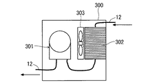
図3は、マルチ画面表示装置1000に冷却装置300が取り付けられた状態を模式的に示す図である。マルチ画面表示装置1000は、1台以上の冷却装置300を利用して、マルチ画面表示装置1000の冷却を行う。
FIG. 3 is a diagram schematically showing a state in which the
詳細は後述するが、冷却装置300は、冷却液体により、マルチ画面表示装置1000を冷却するための装置である。冷却液体とは、マルチ画面表示装置1000を冷却するために使用される液体である。冷却装置300は、当該冷却装置300自身に熱的に接続された要素を冷却する。
Although details will be described later, the
冷却装置300は、マルチ画面表示装置1000の外部に設けられる。すなわち、マルチ画面表示装置1000は、冷却装置300を含まない。なお、冷却装置300は、マルチ画面表示装置1000の内部に設けられてもよい。
The
図3に示されるように、映像表示装置100−1,100−2,100−3,100−4は、それぞれ、投写部11−1,11−2,11−3,11−4を備える。以下においては、投写部11−1,11−2,11−3,11−4の各々を、単に、投写部11とも表記する。投写部11は、映像を投射する。
As illustrated in FIG. 3, the video display devices 100-1, 100-2, 100-3, and 100-4 include projection units 11-1, 11-2, 11-3, and 11-4, respectively. Hereinafter, each of the projection units 11-1, 11-2, 11-3, and 11-4 is also simply referred to as the
まず、各映像表示装置100の構成について説明する。
First, the configuration of each
図4は、実施の形態1に係る映像表示装置100の構成を示すブロック図である。
FIG. 4 is a block diagram showing the configuration of the
図4に示すように、各映像表示装置100は、制御部1と、光源装置2と、ライトバルブ3と、投写レンズ4と、信号処理部6と、画像入力部7と、画面10とを備える。
As shown in FIG. 4, each
制御部1は、映像表示装置100内の各部(例えば、光源装置2)を制御する。
The
光源装置2は、図示しないLEDを含む。光源装置2は、LEDを利用して光を出射する。具体的には、光源装置2は、マルチ画面10Aに映像を表示するための光を出射する。光源装置2からの光は、ライトバルブ3に照射される。
The
画像入力部7は、外部からの映像信号を受信し、当該映像信号を、信号処理部6へ送信する。信号処理部6は、受信した映像信号が示す画像に対し、画像の拡大縮小などの信号(画像)処理を行う。次に、信号処理部6は、信号処理された映像信号を、ライトバルブ3が処理可能なドライブ信号に変換する。そして、信号処理部6は、当該ドライブ信号を、ライトバルブ3へ送信する。
The
ライトバルブ3は、光源装置2(後述の半導体光源)が出射する光の強度を変調する。具体的にはライトバルブ3は、受信するドライブ信号に従って、光源装置2から照射された光を強度変調し、変調後の光を、投写レンズ4を介して、画面10へ照射する。これにより、画面10に映像が投影(表示)される。
The
マルチ画面表示装置1000は、各映像表示装置100が画面10に映像を表示することにより、マルチ画面10Aに映像を表示する。
The
図5は、実施の形態1に係る映像表示装置100の一部の構造を示す断面図である。図5では、図の簡略化のため、画面10の水平方向のサイズは、投写部11の水平方向のサイズより小さく示される。しかしながら、実際には、画面10の水平方向のサイズは、投写部11の水平方向のサイズより大きい。
FIG. 5 is a cross-sectional view showing a partial structure of
図5に示されるように、各映像表示装置100の投写部11は、前述の光源装置2と、前述のライトバルブ3と、前述の投写レンズ4とを含む。
As shown in FIG. 5, the
光源装置2は、半導体光源20a,20b,20cと、ハウジング50とを含む。なお、投写部11は、光源装置2(半導体光源20a,20b,20c等)を冷却するための冷却用ファンを有さない。
The
半導体光源20a,20b,20cの各々は、LEDである。半導体光源20a,20b,20cは、ハウジング50に取り付けられる。以下においては、半導体光源20a,20b,20cの各々を、単に、半導体光源20ともいう。各半導体光源20は、マルチ画面10Aに映像を表示するための光を出射する。
Each of the
なお、半導体光源20a,20b,20cの各々は、LEDに限定されず、光を出射する他の素子から構成されてもよい。また、光源装置2が含む半導体光源20の数は3に限定されない。光源装置2が含む半導体光源20の数は、1、2または4以上であってもよい。
Each of the
半導体光源20aには、図示しない熱伝導体を介して、熱交換ジャケット30aが取り付けられている。熱伝導体は、例えば、熱伝導グリスである。熱伝導体は、接触熱抵抗を低減するものである。半導体光源20aは、熱伝導体を介して、熱交換ジャケット30aと熱的に結合している。
A
半導体光源20bには、図示しない熱伝導体を介して、熱交換ジャケット30bが取り付けられている。半導体光源20bは、半導体光源20aと同様に、熱伝導体を介して、熱交換ジャケット30bと熱的に結合している。
A
半導体光源20cには、図示しない熱伝導体を介して、熱交換ジャケット30cが取り付けられている。半導体光源20cは、半導体光源20aと同様に、熱伝導体を介して、熱交換ジャケット30cと熱的に結合している。
A
次に、マルチ画面表示装置1000における冷却構造について説明する。
Next, a cooling structure in the
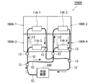
再び、図3を参照して、投写部11−1,11−2,11−3,11−4の各々は、管12および分岐管13により、冷却装置300と接続される。
Again referring to FIG. 3, each of projection units 11-1, 11-2, 11-3, and 11-4 is connected to cooling
管12は、冷却液体を流動させるための流動管である。分岐管13は、1つの管12からの冷却液体を、2つの管12へ送るためのものである。
The
例えば、投写部11−1の一方は、2つの分岐管13を介して、管12により、冷却装置300と接続される。投写部11−1の他方は、2つの分岐管13を介して、管12により、冷却装置300と接続される。投写部11−2,11−3,11−4の各々も、投写部11−1と同様に、冷却装置300と接続される。
For example, one of the projection units 11-1 is connected to the
詳細は後述するが、冷却装置300は、管12を利用して、冷却液体を、各映像表示装置100へ送る。そして、管12を介して、各映像表示装置100から戻ってきた、温度上昇した冷却液体を冷やして、当該冷却液体を、再度、各映像表示装置100へ送る。
Although details will be described later, the
次に、管12と投写部11との接続構造を説明する。
Next, a connection structure between the
再び、図5を参照して、各映像表示装置100の光源装置2内の熱交換ジャケット30a,b,cの各々には、管12が接続される。なお、図5では、管12が切断されているように示されるが、実際には、熱交換ジャケット30a,b,cの各々の内部に、1本の管12が熱的に接続される。以下においては、熱交換ジャケット30a,b,cの各々を、単に、熱交換ジャケット30とも表記する。
Referring to FIG. 5 again, the
以上の構成により、1台の冷却装置300は、複数の映像表示装置100が、それぞれ備える複数の半導体光源20(投写部11内の光源装置2)に熱的に接続され、かつ、複数の半導体光源20(光源装置2)を冷却する。
With the above configuration, one
次に、冷却装置300について説明する。
Next, the
図6は、冷却装置300の内部構成を示す図である。
FIG. 6 is a diagram illustrating an internal configuration of the
冷却装置300は、循環ポンプ301と、放熱器302と、冷却ファン303とを含む。循環ポンプ301は、管12を利用して、冷却液体を送り出す。放熱器302の内部には、管12が貫通する。管12は、放熱器302と熱的に接続される。冷却ファン303は、放熱器302を強制空冷する。
The
次に、冷却液体を利用した冷却について説明する。図3に示すように、冷却装置300の循環ポンプ301は、管12および分岐管13を利用して冷却液体を、各映像表示装置100の投写部11へ送る。すなわち、冷却装置300から送出された冷却液体は、分岐管13により分配され、各映像表示装置100の投写部11へ送られる。冷却液体は、各投写部11の各半導体光源20と熱交換を行うことにより温度が上昇し、再び、管12を通り冷却装置300に戻る。
Next, cooling using a cooling liquid will be described. As shown in FIG. 3, the
各映像表示装置100から戻ってきた、温度上昇した冷却液体は、放熱器302の内部を通ることにより、温度が下げられる(冷却される)。
The cooling liquid that has returned from each
循環ポンプ301は、放熱器302により冷やされた冷却液体を、再び、各映像表示装置100の投写部11へと送り出す。以上により、冷却液体は、各映像表示装置100内を循環する。
The
ここで、分岐管13は、管12との接続解除時に冷却液体が漏れない構造を有する。これにより、映像表示装置100のメンテナンス等において、マルチ画面表示装置1000から一台の映像表示装置100だけ取り出す場合にも対応することが可能となる。
Here, the
なお、本実施の形態では、冷却装置300から各映像表示装置100との間で、冷却液体に対し2段階の分岐を行う構成としている。すなわち、冷却装置300から各映像表示装置100との間に、2つの分岐管13が設けられる。しかしながら、この構成に限定されず、冷却液体に対し1段階の分岐をする構成でもよい。
In this embodiment, the cooling liquid is branched in two stages between the cooling
光源装置2における熱交換は、以下のように行われる。図5のように、冷却液体は、管12を利用して、投写部11の外部から投写部11の内部に引き込まれる。そして、熱交換ジャケット30a,b,cにて、熱交換を行った後、再び、管12により、投写部11の外部へと導かれる。
Heat exchange in the
ここで、LEDにおける温度の影響の受けやすさと発熱量を考慮して、半導体光源20a,20b,20cは以下のように設定される。
Here, the
まず、半導体光源20aは、赤色光を発するLEDとされる。また、半導体光源20bは、青色光を発するLEDとされる。また、半導体光源20cは、緑色光を発するLEDとされる。この場合、管12により、熱交換ジャケット30a,b,cの順に、冷却液体が、熱交換ジャケット30a,b,cの内部を通る。これにより、各熱交換ジャケット30に対応する半導体光源20と熱交換が行われ、半導体光源20(光源装置2)の冷却が行われる。
First, the
以上説明したように、本実施の形態によれば、1台の冷却装置300は、複数の映像表示装置100が、それぞれ備える複数の半導体光源20(投写部11内の光源装置2)に熱的に接続され、かつ、複数の半導体光源20(光源装置2)を冷却する。これにより、映像表示装置100の数だけ冷却装置300を設ける必要がない。そのため、マルチ画面表示装置1000の冷却のためのコストを低減することができる。
As described above, according to the present embodiment, one
また、複数の映像表示装置100の半導体光源20(光源装置2)の冷却をまとめて行うことにより、各映像表示装置100間での温度ばらつきが軽減され半導体光源の温度制御も容易になる。
Further, by collectively cooling the semiconductor light sources 20 (light source devices 2) of the plurality of
従来のマルチ画面表示装置(以下、マルチ画面表示装置Jともいう)は、映像表示装置の数だけ、冷却機構を有する必要がある。なお、半導体光源の冷却に液体冷却を適用する場合、半導体光源の寿命に対し冷却の肝であるポンプの寿命が追い付いておらず、半導体光源が寿命に達する前にポンプが故障してしまう。 A conventional multi-screen display device (hereinafter also referred to as multi-screen display device J) needs to have as many cooling mechanisms as the number of video display devices. In addition, when liquid cooling is applied to the cooling of the semiconductor light source, the life of the pump that is the liver of cooling does not catch up with the life of the semiconductor light source, and the pump fails before the semiconductor light source reaches the end of its life.
そのため、マルチ画面表示装置Jを構成する各映像表示装置が冷却機構を有する場合、ポンプが故障する確率は、マルチ画面表示装置Jを構成する映像表示装置の数が多い程、高くなる。 Therefore, when each video display device constituting the multi-screen display device J has a cooling mechanism, the probability that the pump will fail increases as the number of video display devices constituting the multi-screen display device J increases.
また、マルチ画面表示装置Jは冷却液体の冷却ために、各映像表示装置がファンを有している。そのため、マルチ画面表示装置Jの動作時にはすべての映像表示装置のファンが稼動する。そのため、マルチ画面表示装置Jでは、多くの電力を消費するとともに、大きな騒音を発生することとなる。 Further, in the multi-screen display device J, each video display device has a fan for cooling the cooling liquid. Therefore, when the multi-screen display device J operates, all the video display device fans are operated. Therefore, the multi-screen display device J consumes a lot of power and generates a large noise.
そこで、本実施の形態に係るマルチ画面表示装置1000は、複数の映像表示装置100の各々の各半導体光源20(光源装置2)の冷却を、1台の冷却装置300で行う構成とする。すなわち、複数の映像表示装置100をまとめて冷却を行う構成とする。なお、各映像表示装置100は、半導体光源20(光源装置2)の冷却機構を有さない。
Therefore, the
この構成は、マルチ画面表示装置Jの冷却の構成よりも、冷却のためのポンプおよびファンの数を減らすことができる。これにより、本実施の形態では、マルチ画面表示装置1000の冷却に使用するポンプの故障確率を下げることができる。また、マルチ画面表示装置1000における騒音の低減、消費電力の低減もできる。
This configuration can reduce the number of pumps and fans for cooling than the cooling configuration of the multi-screen display device J. Thereby, in this Embodiment, the failure probability of the pump used for cooling of the
また、冷却装置300は、映像表示装置100の外部に設けられる。そのため、半導体光源20(光源装置2)の排熱を、映像表示装置100の外部で行うことができる。したがって、映像表示装置100自身の放熱を低減することができる。その結果、マルチ画面表示装置1000における上段の映像表示装置100の温度上昇を低減することができる。
The
また、本実施の形態によれば、各映像表示装置100に冷却液体の冷却用ファンを取り付ける必要がない。そのため、使用するファンの総数も減らすことができる。その結果、騒音を低減することができる。また、マルチ画面表示装置1000における各映像表示装置100の各半導体光源20(光源装置2)の冷却を、1台の冷却装置300で行うため、省エネおよびコスト削減にも効果がある。
Further, according to the present embodiment, it is not necessary to attach a cooling liquid cooling fan to each
複数の映像表示装置の半導体光源の冷却を、1台の冷却装置300で行う構成としたことで、当該冷却装置300へのアクセスが容易となり保守の手間を削減することができる。また、半導体光源20(光源装置2)の温度制御もまとめて行うことができ、従来のように、映像表示装置毎に温度制御を行っていた時より容易となる。
Since the cooling of the semiconductor light sources of the plurality of video display devices is performed by the
なお、本実施の形態では、1台の冷却装置300を利用する構成としたがこれに限定されない。マルチ画面表示装置1000を構成する映像表示装置の数より少ない数(1以上の整数)の冷却装置300を利用する構成としてもよい。
In the present embodiment, a
なお、本実施の形態における冷却装置300は、最大で、4台の映像表示装置100を冷却する能力を持っている。マルチ画面表示装置1000を構成する映像表示装置100の数が変わると、1台の冷却装置300につながる映像表示装置100の数は変動する。そこで、冷却装置300につながる映像表示装置100の数に応じて、冷却装置300の冷却能力を変更するようにしてもよい。これにより、冷却に要する消費電力および騒音の低減を行うことができる。
Note that the
(実施の形態1の変形例1)
実施の形態1では、各映像表示装置100の半導体光源20のみを冷却していた。本実施の形態の変形例1では、半導体光源20に加え、ライトバルブ3も同時に冷却を行う。
(
In the first embodiment, only the semiconductor light source 20 of each
図7は、実施の形態1の変形例1に係るマルチ画面表示装置1000Aの構成を示す図である。
FIG. 7 is a diagram showing a configuration of a
図7に示すように、マルチ画面表示装置1000Aは、映像表示装置100A−1,100A−2,100A−3,100A−4を含む。映像表示装置100A−1,100A−2,100A−3,100A−4の各々は、同一の構成を有する。
As shown in FIG. 7, the
映像表示装置100A−1,100A−2,100A−3,100A−4は、それぞれ、図2に示される画面10−1,10−2,10−3,10−4を含む。以下においては、映像表示装置100A−1,100A−2,100A−3,100A−4の各々を、単に、映像表示装置100Aとも表記する。
マルチ画面表示装置1000Aは、マルチ画面表示装置1000と同様に、マルチ画面10Aを含む。
Similar to the
図8は、マルチ画面表示装置1000Aに冷却装置300が取り付けられた状態を模式的に示す図である。
FIG. 8 is a diagram schematically showing a state in which the
図8に示すように、映像表示装置100A−1,100A−2,100A−3,100A−4は、それぞれ、投写部11A−1,11A−2,11A−3,11A−4を備える。以下においては、投写部11A−1,11A−2,11A−3,11A−4の各々を、単に、投写部11Aとも表記する。
As shown in FIG. 8, the
投写部11Aは、投写部11と同様な機能を有する。
The
なお、冷却装置300と各投写部11Aとの接続状態は、図3の冷却装置300と各投写部11との接続状態と同様なので詳細な説明は繰り返さない。
Since the connection state between
図9は、実施の形態1の変形例1に係る映像表示装置100Aの構成を示す図である。映像表示装置100Aは、図5の映像表示装置100と比較して、投写部11の代わりに投写部11Aを備える点が異なる。映像表示装置100Aのそれ以外の構成は、映像表示装置100と同様なので詳細な説明は繰り返さない。
FIG. 9 is a diagram illustrating a configuration of a
投写部11Aは、図5の投写部11と比較して、さらに、受熱ブロック35を含む点が異なる。投写部11Aのそれ以外の構成は、投写部11と同様なので詳細な説明は繰り返さない。
The
受熱ブロック35は、熱を伝えるための熱伝導体である。受熱ブロック35は、ライトバルブ3の背面に熱的に接続される。また、受熱ブロック35の内部に、1本の管12が熱的に接続される。以上の構成より、1台の冷却装置300は、さらに、複数の映像表示装置100Aが、それぞれ備える複数のライトバルブ3に熱的に接続される。
The
なお、1本の管12は、受熱ブロック35および熱交換ジャケット30a,b,cと熱的に接続される。
One
以上の構成の映像表示装置100Aでは、まず、管12により、冷却装置300から送られた冷却液体は、受熱ブロック35の内部を通る。これにより、受熱ブロック35に接続されるライトバルブ3と熱交換が行われ、ライトバルブ3の冷却が行われる。
In the
そして、実施の形態1と同様、管12により、熱交換ジャケット30a,b,cの順に、冷却液体が、熱交換ジャケット30a,b,cの内部を通る。これにより、各熱交換ジャケット30に対応する半導体光源20と熱交換が行われ、半導体光源20(光源装置2)の冷却が行われる。そして、冷却液体は、再び冷却装置300へ戻る。
As in the first embodiment, the cooling liquid passes through the inside of the
以上説明したように、実施の形態1の変形例1の構成によれば、冷却装置300は、複数の半導体光源20(光源装置2)に加え、さらに、複数のライトバルブ3に熱的に接続され、かつ、複数のライトバルブ3を冷却する。これにより、複数の半導体光源20(光源装置2)に加え、さらに、複数のライトバルブ3も同時に冷却することができる。また、実施の形態1の変形例1では、実施の形態1と同様な効果を奏する。すなわち、マルチ画面表示装置1000Aの冷却のためのコストを低減することができる。
As described above, according to the configuration of the first modification of the first embodiment, the
以上の実施の形態1の変形例1の構成は、従来のように各映像表示装置において半導体光源およびライトバルブの冷却構造をもつ構成より、ポンプおよび冷却ファンの数を減らすことができる。その結果、マルチ画面表示装置1000Aにおける、ポンプの故障確率を下げることができる。
The configuration of the first modification of the first embodiment described above can reduce the number of pumps and cooling fans as compared with the conventional configuration in which each image display device has a semiconductor light source and light valve cooling structure. As a result, the failure probability of the pump in the
また、冷却ファンの数が減ったことにより、マルチ画面表示装置1000Aにおける騒音を低減することができる。
Further, since the number of cooling fans is reduced, noise in the
また、本実施の形態1の変形例1では、各映像表示装置100Aから、半導体光源20(光源装置2)およびライトバルブ3の排熱を、外部にある冷却装置300へと送る構成である。この構成により、映像表示装置100Aの発熱量を低減することができる。その結果、マルチ画面表示装置1000Aにおける他の映像表示装置の温度上昇を低減することができる。
In addition, the first modification of the first embodiment is configured such that the exhaust heat of the semiconductor light source 20 (light source device 2) and the
(実施の形態1の変形例2)
実施の形態1では、マルチ画面表示装置の冷却のために、1台の冷却装置を使用していた。本実施の形態の変形例2では、複数の冷却装置を使用した場合の構成を説明する。本実施の形態の変形例2におけるマルチ画面表示装置は、実施の形態1のマルチ画面表示装置1000である。
(
In the first embodiment, one cooling device is used for cooling the multi-screen display device. In the second modification of the present embodiment, a configuration when a plurality of cooling devices are used will be described. The multi-screen display device according to the second modification of the present embodiment is the
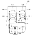
図10は、マルチ画面表示装置1000に冷却装置300,300aが取り付けられた状態を模式的に示す図である。すなわち、本実施の形態の変形例2に係るマルチ画面表示装置1000は、複数の冷却装置を利用する。
FIG. 10 is a diagram schematically illustrating a state in which the
マルチ画面表示装置1000における各映像表示装置100の投写部11と、冷却装置300との接続状態は、図3と同様なので詳細な説明は繰り返さない。
Since the connection state between the
本実施の形態では、冷却装置300と接続される2つの分岐管13に、さらに、冷却装置300aが接続される。すなわち、冷却装置300,300aの各々は、複数の映像表示装置100が、それぞれ備える複数の半導体光源20(投写部11内の光源装置2)に熱的に接続され、かつ、複数の半導体光源20(光源装置2)を冷却する。冷却装置300aは、冷却装置300と同じ機能および構成を有する。
In the present embodiment, the
以上の構成における冷却装置の運転方法は次の様になる。一つ目の運転方法では、通常、冷却装置300が稼働し、各映像表示装置100の半導体光源20(投写部11内の光源装置2)の冷却を行う。冷却装置300が故障した場合、冷却装置300aを稼動させ、冷却装置300aに冷却のための動作を行わせる。すなわち、冷却装置300aは、冷却装置300の故障時等に使用される予備の装置として利用する。
The operation method of the cooling device in the above configuration is as follows. In the first operation method, the
二つ目の運転方法は、定期的に、冷却を行う冷却装置を切り替えて運転する方法である。運転中に一台が故障した場合は、故障していない冷却装置のみで冷却を行う。 The second operation method is a method in which a cooling device that performs cooling is switched periodically. If one unit fails during operation, cooling is performed only with a cooling device that does not fail.
このように、冷却装置を複数台持つことで、一つの冷却装置が故障しても、マルチ画面表示装置1000の冷却が停止されることを防ぐことができる。
Thus, by having a plurality of cooling devices, it is possible to prevent the cooling of the
本実施の形態の変形例2では、4台の映像表示装置に対し、2台の冷却装置を用いる構成としたが、これに限定されず、3台以上の冷却装置を用いてもよい。
In
以上説明したように、実施の形態1の変形例2では、複数の冷却装置の各々は、複数の映像表示装置100が、それぞれ備える複数の半導体光源20(光源装置2)に熱的に接続される。これにより、一つの冷却装置が故障しても、マルチ画面表示装置1000の冷却が停止されることを防ぐことができる。
As described above, in the second modification of the first embodiment, each of the plurality of cooling devices is thermally connected to the plurality of semiconductor light sources 20 (light source devices 2) included in the plurality of
なお、本実施の形態の変形例2の構成は、実施の形態1の変形例1のマルチ画面表示装置1000Aにも適用できる。すなわち、図8において、冷却装置300と接続される2つの分岐管13に、さらに、冷却装置300aを接続する構成としてもよい。
The configuration of the second modification of the present embodiment can also be applied to the
なお、本発明は、その発明の範囲内において、実施の形態、実施の形態の変形例を自由に組み合わせたり、各実施の形態、実施の形態の変形例を適宜、変形、省略することが可能である。 It should be noted that within the scope of the invention, the present invention can be freely combined with the embodiments and modifications of the embodiments, or can be appropriately modified and omitted according to the embodiments and the modifications of the embodiments. It is.
本発明は、冷却のためのコストを低減したマルチ画面表示装置として、利用することができる。 The present invention can be used as a multi-screen display device with reduced cost for cooling.
2 光源装置、3 ライトバルブ、11,11−1,11−2,11−3,11−4,11A,11A−1,11A−2,11A−3,11A−4 投写部、12 管、13 分岐管、20a,20b,20c 半導体光源、100,100−1,100−2,100−3,100−4,100A,100A−1,100A−2,100A−3,100A−4 映像表示装置、300,300a 冷却装置、1000,1000A マルチ画面表示装置。 2 light source device, 3 light bulb, 11, 11-1, 11-2, 11-3, 11-4, 11A, 11A-1, 11A-2, 11A-3, 11A-4 projection unit, 12 tube, 13 Branch tube, 20a, 20b, 20c semiconductor light source, 100, 100-1, 100-2, 100-3, 100-4, 100A, 100A-1, 100A-2, 100A-3, 100A-4 video display device, 300,300a Cooling device, 1000,1000A Multi-screen display device.
Claims (3)
前記マルチ画面表示装置は、画面を有する複数の映像表示装置を含み、
前記複数の映像表示装置が、それぞれ有する複数の前記画面からマルチ画面が構成され、
各前記映像表示装置は、
前記マルチ画面に映像を表示するための光を出射する半導体光源を備え、
前記1台以上の冷却装置のうちの1台の冷却装置は、前記複数の映像表示装置が、それぞれ備える複数の前記半導体光源に熱的に接続され、かつ、前記複数の半導体光源を冷却する
マルチ画面表示装置。 A multi-screen display device that uses one or more cooling devices,
The multi-screen display device includes a plurality of video display devices having a screen,
The plurality of video display devices each have a plurality of screens to form a multi-screen,
Each of the video display devices
A semiconductor light source that emits light for displaying an image on the multi-screen;
One cooling device of the one or more cooling devices is thermally connected to the plurality of semiconductor light sources provided in the plurality of video display devices, respectively, and cools the plurality of semiconductor light sources. Screen display device.
前記半導体光源が出射する光の強度を変調するライトバルブを備え、
前記1台の冷却装置は、さらに、前記複数の映像表示装置が、それぞれ備える複数の前記ライトバルブに熱的に接続され、かつ、前記複数のライトバルブを冷却する
請求項1に記載のマルチ画面表示装置。 Each of the video display devices further includes:
A light valve for modulating the intensity of light emitted by the semiconductor light source;
The multi-screen according to claim 1, wherein the one cooling device is further thermally connected to the plurality of light valves provided in the plurality of video display devices, respectively, and cools the plurality of light valves. Display device.
各前記冷却装置は、前記複数の半導体光源に熱的に接続され、かつ、前記複数の半導体光源を冷却する
請求項1または2に記載のマルチ画面表示装置。 The multi-screen display device uses a plurality of the cooling devices,
The multi-screen display device according to claim 1, wherein each of the cooling devices is thermally connected to the plurality of semiconductor light sources and cools the plurality of semiconductor light sources.
Priority Applications (3)
| Application Number | Priority Date | Filing Date | Title |
|---|---|---|---|
| JP2012031227A JP2013167774A (en) | 2012-02-16 | 2012-02-16 | Multi-screen display device |
| US13/712,691 US20130214997A1 (en) | 2012-02-16 | 2012-12-12 | Multi-screen display apparatus |
| CN201310024204.4A CN103257518B (en) | 2012-02-16 | 2013-01-23 | Multi-screen display device |
Applications Claiming Priority (1)
| Application Number | Priority Date | Filing Date | Title |
|---|---|---|---|
| JP2012031227A JP2013167774A (en) | 2012-02-16 | 2012-02-16 | Multi-screen display device |
Publications (2)
| Publication Number | Publication Date |
|---|---|
| JP2013167774A true JP2013167774A (en) | 2013-08-29 |
| JP2013167774A5 JP2013167774A5 (en) | 2015-01-29 |
Family
ID=48961516
Family Applications (1)
| Application Number | Title | Priority Date | Filing Date |
|---|---|---|---|
| JP2012031227A Pending JP2013167774A (en) | 2012-02-16 | 2012-02-16 | Multi-screen display device |
Country Status (3)
| Country | Link |
|---|---|
| US (1) | US20130214997A1 (en) |
| JP (1) | JP2013167774A (en) |
| CN (1) | CN103257518B (en) |
Cited By (2)
| Publication number | Priority date | Publication date | Assignee | Title |
|---|---|---|---|---|
| WO2018225254A1 (en) * | 2017-06-09 | 2018-12-13 | Necディスプレイソリューションズ株式会社 | Light source device, projector, and method for starting light source device |
| US10564530B2 (en) | 2017-10-25 | 2020-02-18 | Seiko Epson Corporation | Projector with homogenized cooling of light source array |
Families Citing this family (1)
| Publication number | Priority date | Publication date | Assignee | Title |
|---|---|---|---|---|
| CN110342454B (en) * | 2019-07-11 | 2022-03-04 | 电子科技大学 | Heat dissipation device of inertial navigation module |
Citations (8)
| Publication number | Priority date | Publication date | Assignee | Title |
|---|---|---|---|---|
| JPH11282361A (en) * | 1998-03-27 | 1999-10-15 | Mitsubishi Electric Corp | Image display unit |
| JP2000029140A (en) * | 1998-07-07 | 2000-01-28 | Toshiba Corp | Multi-display filter device |
| JP2002101363A (en) * | 2000-09-22 | 2002-04-05 | Mitsubishi Electric Corp | Projection type image display device |
| JP2009075236A (en) * | 2007-09-19 | 2009-04-09 | Sanyo Electric Co Ltd | Cooling device for projector |
| JP2010117573A (en) * | 2008-11-13 | 2010-05-27 | Mitsubishi Electric Corp | Image display apparatus |
| JP2010256558A (en) * | 2009-04-23 | 2010-11-11 | Sanyo Electric Co Ltd | Projection type video display |
| JP2011248086A (en) * | 2010-05-27 | 2011-12-08 | Mitsubishi Electric Corp | Multi-screen display apparatus |
| WO2011152217A1 (en) * | 2010-05-31 | 2011-12-08 | 日本電気株式会社 | Display device |
Family Cites Families (8)
| Publication number | Priority date | Publication date | Assignee | Title |
|---|---|---|---|---|
| JPH04361248A (en) * | 1991-06-07 | 1992-12-14 | Sony Corp | Display device for multi-image system |
| US7264359B2 (en) * | 2003-05-30 | 2007-09-04 | Matsushita Electric Industrial Co., Ltd. | Cooling apparatus |
| JP4654664B2 (en) * | 2004-01-13 | 2011-03-23 | セイコーエプソン株式会社 | Light source device and projection display device |
| JP4657022B2 (en) * | 2004-10-15 | 2011-03-23 | 三洋電機株式会社 | Projection display device |
| CN100498512C (en) * | 2004-10-15 | 2009-06-10 | 三洋电机株式会社 | Projection type video display apparatus |
| CN101063798B (en) * | 2006-04-27 | 2010-06-16 | 三洋电机株式会社 | Projection-type image display device |
| JP2008192579A (en) * | 2007-02-08 | 2008-08-21 | Seiko Epson Corp | Light source device, illuminating device, and projector |
| US8373841B2 (en) * | 2007-11-16 | 2013-02-12 | Manufacturing Resources International, Inc. | Shared isolated gas cooling system for oppositely facing electronic displays |
-
2012
- 2012-02-16 JP JP2012031227A patent/JP2013167774A/en active Pending
- 2012-12-12 US US13/712,691 patent/US20130214997A1/en not_active Abandoned
-
2013
- 2013-01-23 CN CN201310024204.4A patent/CN103257518B/en not_active Expired - Fee Related
Patent Citations (8)
| Publication number | Priority date | Publication date | Assignee | Title |
|---|---|---|---|---|
| JPH11282361A (en) * | 1998-03-27 | 1999-10-15 | Mitsubishi Electric Corp | Image display unit |
| JP2000029140A (en) * | 1998-07-07 | 2000-01-28 | Toshiba Corp | Multi-display filter device |
| JP2002101363A (en) * | 2000-09-22 | 2002-04-05 | Mitsubishi Electric Corp | Projection type image display device |
| JP2009075236A (en) * | 2007-09-19 | 2009-04-09 | Sanyo Electric Co Ltd | Cooling device for projector |
| JP2010117573A (en) * | 2008-11-13 | 2010-05-27 | Mitsubishi Electric Corp | Image display apparatus |
| JP2010256558A (en) * | 2009-04-23 | 2010-11-11 | Sanyo Electric Co Ltd | Projection type video display |
| JP2011248086A (en) * | 2010-05-27 | 2011-12-08 | Mitsubishi Electric Corp | Multi-screen display apparatus |
| WO2011152217A1 (en) * | 2010-05-31 | 2011-12-08 | 日本電気株式会社 | Display device |
Cited By (3)
| Publication number | Priority date | Publication date | Assignee | Title |
|---|---|---|---|---|
| WO2018225254A1 (en) * | 2017-06-09 | 2018-12-13 | Necディスプレイソリューションズ株式会社 | Light source device, projector, and method for starting light source device |
| JPWO2018225254A1 (en) * | 2017-06-09 | 2020-04-09 | Necディスプレイソリューションズ株式会社 | Light source device, projector, and method of starting light source device |
| US10564530B2 (en) | 2017-10-25 | 2020-02-18 | Seiko Epson Corporation | Projector with homogenized cooling of light source array |
Also Published As
| Publication number | Publication date |
|---|---|
| CN103257518A (en) | 2013-08-21 |
| CN103257518B (en) | 2016-01-20 |
| US20130214997A1 (en) | 2013-08-22 |
Similar Documents
| Publication | Publication Date | Title |
|---|---|---|
| US20050168990A1 (en) | Light source apparatus and projection display apparatus | |
| US8944638B2 (en) | Light source device and projection type display device including the same | |
| US7740379B2 (en) | Illumination module and projection apparatus | |
| JP5804522B2 (en) | Display device | |
| US8052282B2 (en) | Heat dissipation system and electronic device utilizing the same | |
| US9261760B2 (en) | Projection apparatus having illumination system and associated ion fan | |
| KR20150083765A (en) | Projection image display device | |
| JP2008176079A (en) | Cooling device | |
| US20190171092A1 (en) | Projection-type display device | |
| US20100033689A1 (en) | Cooling solution for a solid state light illuminated display | |
| JP2011186350A (en) | Illuminator and projection type image display device | |
| TW201430477A (en) | Cooling apparatus of projector | |
| TW201430478A (en) | Cooling apparatus of projector | |
| JP4657242B2 (en) | Projection display device | |
| JP2013167774A (en) | Multi-screen display device | |
| JP4811190B2 (en) | LCD display | |
| JP2009163075A (en) | Projection type video display apparatus | |
| JP2007127856A (en) | Projection display apparatus | |
| JP6246414B2 (en) | Semiconductor laser light source device, semiconductor laser light source system, and video display device | |
| WO2014163342A1 (en) | Display device | |
| JP2005045062A (en) | Light source device and projection type display device using the same | |
| CN109643047A (en) | Image projection device | |
| TW200909989A (en) | Projection device and heat dissipation method | |
| JP2004333757A (en) | Light source device and projection display apparatus using the same | |
| JP2015118305A (en) | Ebullient cooling system and projection type display device |
Legal Events
| Date | Code | Title | Description |
|---|---|---|---|
| A521 | Request for written amendment filed |
Free format text: JAPANESE INTERMEDIATE CODE: A523 Effective date: 20141209 |
|
| A621 | Written request for application examination |
Free format text: JAPANESE INTERMEDIATE CODE: A621 Effective date: 20141209 |
|
| A977 | Report on retrieval |
Free format text: JAPANESE INTERMEDIATE CODE: A971007 Effective date: 20150909 |
|
| A131 | Notification of reasons for refusal |
Free format text: JAPANESE INTERMEDIATE CODE: A131 Effective date: 20150929 |
|
| A02 | Decision of refusal |
Free format text: JAPANESE INTERMEDIATE CODE: A02 Effective date: 20160315 |