JP4811190B2 - LCD display - Google Patents
LCD display Download PDFInfo
- Publication number
- JP4811190B2 JP4811190B2 JP2006224829A JP2006224829A JP4811190B2 JP 4811190 B2 JP4811190 B2 JP 4811190B2 JP 2006224829 A JP2006224829 A JP 2006224829A JP 2006224829 A JP2006224829 A JP 2006224829A JP 4811190 B2 JP4811190 B2 JP 4811190B2
- Authority
- JP
- Japan
- Prior art keywords
- heat
- liquid crystal
- heat exchanger
- cooling
- air
- Prior art date
- Legal status (The legal status is an assumption and is not a legal conclusion. Google has not performed a legal analysis and makes no representation as to the accuracy of the status listed.)
- Expired - Fee Related
Links
Images


Description
本発明は、外部よりのごみや塵埃の進入を阻止する密閉構造とされた電子機器に係わり、水冷方式の熱輸送デバイスを使用して冷却風を形成し、電子機器に搭載された発熱体を冷却する液晶表示機器に関する。 The present invention relates to an electronic device having a sealed structure that prevents entry of dust and dust from the outside. A cooling air is formed by using a water-cooled heat transport device, and a heating element mounted on the electronic device is provided. The present invention relates to a liquid crystal display device to be cooled.
図2は従来の液晶表示機器の概略構成図である。図2に示される従来の液晶表示機器は、ライトバブルとして液晶パネルを備え、白熱灯光源からの光を変調し、液晶パネル上の画像情報をスクリーン上に投射して表示するプロジェクタとして構成されている。画像情報を投射するためのこの光源からの光は、液晶パネルの液晶層を通過する。液晶パネルは、この光通過に伴って光吸収するとともに、不要光源を遮断するブラックマスクにおいても光吸収することになる。よって、液晶パネルはこの光吸収によって温度上昇することになる。また、光源からの光における所定の偏光軸を有さない光は、液晶パネル前後に配置される偏光板によって吸収されることから、偏光板においても熱が蓄積され、この熱が近傍に配置されている液晶パネルにも影響を与える。この液晶パネルでの発熱は液晶パネル自体の寿命を劣化させるだけでなく、過度の温度上昇によっては破損してしまうことになる。そのため、白熱灯光源によって光を投射されている液晶表示機器は、液晶パネルや偏光板の温度上昇を抑制するために液晶パネルや偏光板を冷却しながら使用している。 FIG. 2 is a schematic configuration diagram of a conventional liquid crystal display device. The conventional liquid crystal display device shown in FIG. 2 includes a liquid crystal panel as a light bubble, and is configured as a projector that modulates light from an incandescent light source and projects image information on the liquid crystal panel on a screen for display. Yes. Light from this light source for projecting image information passes through the liquid crystal layer of the liquid crystal panel. The liquid crystal panel absorbs light along with the passage of light, and also absorbs light in a black mask that blocks unnecessary light sources. Therefore, the temperature of the liquid crystal panel rises due to this light absorption. In addition, light that does not have a predetermined polarization axis in the light from the light source is absorbed by the polarizing plates disposed before and after the liquid crystal panel, so that heat is also accumulated in the polarizing plates, and this heat is disposed in the vicinity. It also affects the LCD panel. This heat generation in the liquid crystal panel not only deteriorates the life of the liquid crystal panel itself, but also breaks due to excessive temperature rise. Therefore, a liquid crystal display device in which light is projected by an incandescent lamp light source is used while cooling the liquid crystal panel or the polarizing plate in order to suppress the temperature rise of the liquid crystal panel or the polarizing plate.
従来から液晶表示機器の液晶パネル及び偏光板の冷却は、他の電子機器において行われている同様の方法である機器内部に設置されたファンで外気を冷却風として取り込み被冷却体に通風する空冷方法が一般的に実施されている。 Conventionally, cooling of liquid crystal panels and polarizing plates of liquid crystal display devices is the same method used in other electronic devices. Air cooling that takes outside air as cooling air with a fan installed inside the device and passes it to the object to be cooled. The method is commonly practiced.
近年、液晶表示機器の使用状態の多様化によって表示画面の高輝度化の要求も大きく、この液晶表示機器の液晶パネルに照射される光は、より強いものになっている。一方、市場での製品の廉価への要求も大きく、使用される液晶パネルはますます小型化している。これらの要因等が合わさって、液晶パネルの発熱密度は非常に大きなものとなっている。この温度上昇は、前述したように液晶パネルの品質劣化をも加速させることになり、液晶表示機器の製品自体の寿命への大きな問題となるため、自ずと冷却装置における冷却能力の向上を要求することになる。 In recent years, the demand for higher brightness of the display screen has been increased due to diversification of the usage state of the liquid crystal display device, and the light applied to the liquid crystal panel of the liquid crystal display device has become stronger. On the other hand, there is a great demand for low-priced products in the market, and the liquid crystal panels used are becoming smaller and smaller. Combined with these factors, the heat generation density of the liquid crystal panel is very large. As described above, this temperature increase also accelerates the deterioration of the quality of the liquid crystal panel and becomes a big problem for the life of the liquid crystal display product itself. Therefore, it is necessary to naturally improve the cooling capacity of the cooling device. become.
一方、液晶表示機器は、光を照射し、拡大投射して表示する機器であるため、機器内部に外部からごみや塵埃を吸引してしまうと、これらを照射光によって表示することから、画質劣化として即座に現れる。よって、液晶パネルの冷却には外部から空気を吸引しない冷却方法が望まれている。 On the other hand, liquid crystal display devices are devices that irradiate light and display an enlarged projection, so if dust or dust is sucked into the device from the outside, it will be displayed by the irradiating light. As it appears instantly. Therefore, a cooling method that does not suck air from the outside is desired for cooling the liquid crystal panel.
このごみや塵埃の対応を図りながら冷却能力を向上する方法として、従来からのファンによる一般的な空冷方式に換えて、液冷媒による冷却方式が色々と検討されている。この液冷媒の冷却方式の一つの例として、例えば、特開平1−159684号公報(特許文献1)に記載の冷却装置がある。この冷却装置は、液体冷媒を封入した受熱部材を液晶パネルと偏光板の間に密接して配置し、液晶パネルと偏光板において発熱した熱を液体冷媒に伝達し、受熱した液体冷媒を液体ポンプによって離間した位置に配置されたラジエータに移送して、このラジエータによって放熱するものである。この液体冷媒の冷却に最適な熱交換状態は、受熱部材とラジエータの形態や構造によって対応している。 As a method for improving the cooling capacity while dealing with dust and dust, various cooling methods using a liquid refrigerant have been studied in place of the conventional air cooling method using a fan. As an example of the cooling method of this liquid refrigerant, there is a cooling device described in, for example, JP-A-1-159684 (Patent Document 1). In this cooling device, a heat receiving member enclosing a liquid refrigerant is disposed in close contact between the liquid crystal panel and the polarizing plate, heat generated in the liquid crystal panel and the polarizing plate is transferred to the liquid refrigerant, and the received liquid refrigerant is separated by a liquid pump. It is transferred to a radiator arranged at the position, and the radiator dissipates heat. The optimal heat exchange state for cooling the liquid refrigerant corresponds to the form and structure of the heat receiving member and the radiator.
また、液晶表示機器の液晶パネル等の冷却に関し、液体冷媒の循環方式を取りながらも、ごみや塵埃等の画質劣化に対応した冷却方法として、例えば、特開2005−275189号公報(特許文献2)に記載の冷却装置がある。この冷却装置は、光源が照射される液晶パネルモジュールの光透過領域を除く周辺の領域のみに液体冷媒を通流させる流路を有する受熱部材を設けた構造にしている。液晶パネルの光源によって照射されて発熱した熱は、液晶パネル周辺を通流する液体冷媒位置まで熱伝導させて液体冷媒に受熱させ、受熱した液体冷媒をポンプによって離間した位置に配置された放熱ユニットに移送して、この放熱ユニットで放熱するものであるので、液体冷媒が直接光の照射を受けることがないようにしたものである。 In addition, regarding cooling of a liquid crystal panel or the like of a liquid crystal display device, for example, as a cooling method corresponding to image quality deterioration such as dust and dust while adopting a liquid refrigerant circulation method, for example, JP-A-2005-275189 (Patent Document 2) ). This cooling device has a structure in which a heat receiving member having a flow path for allowing a liquid refrigerant to flow only in a peripheral region excluding a light transmission region of a liquid crystal panel module irradiated with a light source. The heat generated by the light emitted from the light source of the liquid crystal panel is conducted to the liquid refrigerant position flowing around the liquid crystal panel to be received by the liquid refrigerant, and the received liquid refrigerant is disposed at a position separated by the pump. In this case, the liquid refrigerant is not directly irradiated with light.
さらには、液晶表示機器へのごみや塵埃の混入を抑制しながら、液晶パネル等の発熱体を冷却する冷却装置として、例えば、特開2005−148624号公報(特許文献3)に記載の冷却方法がある。この冷却方法は、筐体によって液晶表示装置を密閉状態にし、筐体内部の空気をコンプレッサによって吸入し、圧縮した後にノズルより発熱体に向けて放射する。このノズルから噴射される空気流は断熱膨張によって温度低下した空気流となることで、この温度低下した冷風が発熱体を冷却するものである。この際、圧縮時に起きる温度上昇は圧縮した空気を溜める容器に放熱フィンを設け、フィンを外気に熱接続させて放熱している。 Furthermore, as a cooling device that cools a heating element such as a liquid crystal panel while suppressing entry of dust and dust into the liquid crystal display device, for example, a cooling method described in JP-A-2005-148624 (Patent Document 3) There is. In this cooling method, the liquid crystal display device is hermetically sealed by the casing, the air inside the casing is sucked by the compressor, and after being compressed, is radiated from the nozzle toward the heating element. The air flow ejected from the nozzle becomes an air flow whose temperature is reduced by adiabatic expansion, and the cold air whose temperature has been reduced cools the heating element. At this time, the rise in temperature that occurs during compression is performed by dissipating heat by providing heat-dissipating fins in a container that stores the compressed air and thermally connecting the fins to the outside air.
また、密閉した電子機器の筐体内部の空気を冷却して、筐体内部に設けた送風装置によって発熱体に送風する冷却装置として、例えば、特開2005−121250号公報(特許文献4)に記載の冷却装置がある。この冷却装置は、冷却風を熱電変換素子によって形成するものである。熱電変換素子の低温部を電子機器の内側に取り付け、筐体内部の空気を吸気して冷却して冷却風とし、冷却風を送風路によって被冷却体近傍まで送風して、被冷却体に通風して被冷却体を冷却するものである。熱電変換素子の高温部は、筐体外部に取り付けて筐体内部への影響を回避させている。 Further, as a cooling device that cools air inside a casing of a sealed electronic device and blows air to a heating element by a blower provided inside the casing, for example, in JP-A-2005-121250 (Patent Document 4). There is a cooling device as described. This cooling device forms cooling air by a thermoelectric conversion element. Attach the low temperature part of the thermoelectric conversion element to the inside of the electronic device, suck the air inside the housing and cool it down to make cooling air, blow the cooling air to the vicinity of the body to be cooled through the air passage, and ventilate it Thus, the object to be cooled is cooled. The high temperature part of the thermoelectric conversion element is attached outside the casing to avoid the influence on the inside of the casing.
ここで、上記した従来の液晶表示機器についてみると、液晶表示機器の光源としては白熱灯を使用している。この白熱灯は、熱を出すことによって光を得ているため、投射画面を明るくするために光源の明るさを増大することは、これに対応して液晶パネル等に蓄積される熱を増加させることになる。よって、液晶表示機器の高輝度化における液晶パネルの品質確保のために、より高い冷却性能を有する冷却方法が検討されている。 Here, regarding the conventional liquid crystal display device described above, an incandescent lamp is used as the light source of the liquid crystal display device. Since this incandescent lamp obtains light by producing heat, increasing the brightness of the light source to brighten the projection screen increases the heat stored in the liquid crystal panel or the like correspondingly. It will be. Therefore, in order to ensure the quality of the liquid crystal panel in increasing the brightness of the liquid crystal display device, a cooling method having higher cooling performance has been studied.
一方で、近年、この白熱灯の光源に替えて、同じ明るさを得るに消費電力がおおよそ1/5〜1/10程度である半導体発光素子(LED)の使用が検討され始めている。この例として、例えば,特開2005−345767号公報(特許文献5)がある。この半導体発光素子は、電気が直接光になる現象を利用していることから発熱量が小さく、液晶パネルでの発熱を抑制できるなど冷却の観点でも視点を変える大きな要因といえる。 On the other hand, in recent years, in place of the light source of the incandescent lamp, use of a semiconductor light emitting element (LED) whose power consumption is about 1/5 to 1/10 has been started to obtain the same brightness. An example of this is, for example, Japanese Patent Laid-Open No. 2005-345767 (Patent Document 5). This semiconductor light-emitting element uses a phenomenon in which electricity becomes direct light, so that it generates a small amount of heat and can be said to be a major factor that changes the viewpoint from the viewpoint of cooling, such as suppressing heat generation in a liquid crystal panel.
ただ、上記した従来技術においては、解決しなければならない課題がある。 However, the above-described conventional technology has a problem to be solved.
特許文献1に記載の冷却装置では、光源から照射される光によって液晶パネル、および偏光板の光通過領域に生じる熱を液体冷媒に効率よく伝達させるために、内部に液体冷媒が充填された冷却室を液晶パネルの光透過領域に設けている。この液体冷媒で受熱して、受熱した液体冷媒を液体ポンプで循環させて離間した位置に配置されたラジエータ等の放熱部材で放熱する方法で熱交換能力の向上を図っている。しかし、光源から照射される光が液体冷媒を透過するため、気泡や塵埃が液体冷媒に混入すると画像に気泡や塵埃の映像が投射されてしまう問題がある。また、冷却室内の液体冷媒に温度差が生じると液体冷媒の対流などによって画像に揺らぎが発生する問題や、さらには、液体冷媒が光源から照射された光によって変質して、光の液晶パネルの透過率が低下し、表示画像の照度低下を生じてしまう問題を呈する。
In the cooling device described in
特許文献2に記載の冷却装置では、光源から照射する光が透過する領域を避けた領域で冷却冷媒を循環させて液晶パネル等を冷却しているので、冷却冷媒における光の照射によって生じる上記の問題は回避できるが、逆に、液晶パネルや偏光板での光源から照射される光の通過領域の熱を光の通過領域の周辺への冷却冷媒に効率良く伝達する必要があり、この熱伝達のために光透過率が良く、熱伝導率の高い高光透過、高熱伝導材の熱伝達部材が用いられることになる。現状では、この熱伝達部材としての高光透過、高熱伝導材は限られた材質であり高価なものとなって、商業製品としてのコスト的な課題となっている。また、冷却ユニットにより吸入される空気中のごみや塵埃の対策としては、高価で取り扱いに注意を有する高熱伝導材や液晶パネルの表面部に防塵ガラス等を設置した液晶表示装置もあり、構造の複雑化になる。
In the cooling device described in
特許文献3に記載の冷却装置は、電子機器を筐体により密閉状態に構成しており、機器内部における空気を吸引して圧縮し、噴射による断熱膨張で急冷する冷却風によって発熱体を冷却するものであり、外部よりの空気の吸引等がないことからごみや塵埃の問題は解決されるとともに、低温になった冷却風が発熱体に近接して直接噴射されるために冷却性能の向上も可能であり、期待の大きい冷却方法である。噴射される空気の圧力や温度の制御は、コンプレッサによる圧縮状態を制御することで可能となるが、コンプレッサのような特別の装置を必要としたり、断熱膨張による空気の急冷により機器内部の空気中の水分が水滴化することの問題も想定される。この空気中の水分による水滴が液晶パネル等に付着すると映像の劣化を招くことになる。また、コンプレッサによる空気流の噴射周期等によって液晶パネルの温度に周期変動が生じ、その周期状態によっては映像への影響も懸念される。 The cooling device described in Patent Document 3 is configured such that an electronic device is hermetically sealed by a housing, and the heating element is cooled by cooling air that sucks and compresses air inside the device and rapidly cools by adiabatic expansion by jetting. The problem of dust and dust is solved because there is no air suction from the outside, and the cooling performance is improved because the cooled cooling air is injected directly close to the heating element. This is a cooling method that is possible and has high expectations. The pressure and temperature of the injected air can be controlled by controlling the compression state by the compressor, but a special device such as a compressor is required, or the air inside the equipment is rapidly cooled by adiabatic expansion. A problem of water droplets forming into water droplets is also assumed. When water droplets due to moisture in the air adhere to a liquid crystal panel or the like, the image is deteriorated. Further, the temperature of the liquid crystal panel varies periodically due to the air flow injection period of the compressor, etc., and depending on the periodic state, there is a concern about the influence on the image.
特許文献4に記載の冷却装置では、密閉した筐体内部の空気を循環するため、ごみや塵埃の取り込みの問題もなく、内部の空気の冷却も熱電変換素子によるものであり冷媒循環等の機構部品等も削減でき、冷媒液や機構部品に関する問題もなく好適な冷却方法と考えられる。ただ、未だ、熱電変換素子や、この素子の駆動回路などの価格が高く十分な普及に至っていない。また、熱電変換素子は、半導体接合部に電流を流すことにより半導体の接合部に吸熱現象と放熱現象が生じることによるため、伝熱板の低温部に対向する部分が高温部となることから、この隣接する高温部の発熱に対する二次的な冷却の工夫が必要となる。 The cooling device described in Patent Document 4 circulates air inside a sealed casing, so there is no problem of taking in dust and dust, and cooling of the internal air is also due to a thermoelectric conversion element. It is possible to reduce the number of parts and the like, and it is considered to be a suitable cooling method without any problems related to the refrigerant liquid and mechanism parts. However, the price of the thermoelectric conversion element and the drive circuit for this element is still high and has not yet been widely spread. In addition, since the thermoelectric conversion element is caused by the endothermic phenomenon and the heat radiation phenomenon in the semiconductor junction by flowing current through the semiconductor junction, the portion facing the low temperature part of the heat transfer plate becomes the high temperature part. It is necessary to devise a secondary cooling for the heat generation in the adjacent high temperature portion.
特許文献5に記載の液晶表示機器は、光源に半導体発光素子を使用しているので、光源からの液晶パネル等への熱照射が大幅に低減されるばかりでなく、半導体発光素子から単色光源として直接液晶パネル等に入射すればよく、色分離光学系を割愛できるメリットや、単色で色調整が行えるメリットがあり、液晶表示機器の光源として大いに期待されるものである。しかし、現状では、未だ、半導体発光素子1つの光量が小さく、複数個をまとめて使用する必要があり、白熱灯と同じ明るさを得るには、数10個〜数100個を必要とされ、コスト的にも、スペース的にも使い難い状況にある。
Since the liquid crystal display device described in
本発明は、光を投射するような液晶表示機器において、液晶パネルへの熱への影響を抑制して信頼性を向上し、ごみや塵埃の混入を防止して画質の劣化を回避するに最適な冷却装置を有する液晶表示装置を提供するためのものである。 The present invention is most suitable for liquid crystal display devices that project light, to improve the reliability by suppressing the influence on the heat to the liquid crystal panel, to prevent the mixing of dust and dust and to avoid the deterioration of image quality It is for providing a liquid crystal display device having a cooling device.
本発明は、半導体発光素子による複数の単色光の光源と、複数の単色光の光源から各々の光を照射される複数のライトバルブと、複数のライトバルブによって形成される情報を合成し、投射する光学部材とを備え、略密閉した筐体で構成される液晶表示機器において、複数の各々の光源は、光を照射する背面側にヒートシンクを一体的に有する構成とし、ヒートシンクを介して光源を冷却する冷却装置は、冷媒を通流する配管を備え、表示機器の筐体の内部に載置される第1の熱交換器と、冷媒を通流する配管を備え、表示機器の筐体の外部に設置される第2の熱交換器との間で冷媒を循環し、第1の熱交換器において冷媒により受熱し、第2の熱交換器によって冷媒から放熱する構成となし、密閉された筐体の内部の空気を第1の熱交換器に通風して、第1の熱交換器によって筐体の内部の空気を低温風となして、第1の熱交換器から送出した低温風を複数の光源のヒートシンクに通風して複数の光源を冷却する構成としている。 The present invention combines a plurality of monochromatic light sources by a semiconductor light emitting element, a plurality of light valves irradiated with each light from the plurality of monochromatic light sources, and information formed by the plurality of light valves, and is projected. In a liquid crystal display device comprising a substantially hermetically sealed housing, each of the plurality of light sources has a structure in which a heat sink is integrally provided on the back side that irradiates light, and the light source is provided via the heat sink. The cooling device for cooling includes a pipe through which the refrigerant flows, and includes a first heat exchanger placed inside the casing of the display device, a pipe through which the refrigerant flows, and the casing of the display device. The refrigerant is circulated between the second heat exchanger installed outside, the first heat exchanger receives heat from the refrigerant, and the second heat exchanger dissipates heat from the refrigerant. The air inside the housing is converted into the first heat exchanger Ventilate and change the air inside the housing to low temperature air by the first heat exchanger, and cool the plurality of light sources by passing the low temperature air sent from the first heat exchanger through the heat sinks of the plurality of light sources. It is configured to do.
さらには、第1の熱交換器に通風された空気を光源のヒートシンクに送風する送風路を第1の熱交換器に隣接して備えて、低温風を送風路の噴出し口より複数の光源のヒートシンクに通風する構成としている。 Furthermore, the air passage which ventilates the air ventilated to the 1st heat exchanger to the heat sink of a light source is provided adjacent to the 1st heat exchanger, and a plurality of light sources are provided with low temperature air from the outlet of the air passage. It is configured to ventilate the heat sink.
さらには、冷却装置を、第1の熱交換器と、第2の熱交換器と、タンクと、ポンプとを第1の配管群によって接続して冷媒を循環する構成とし、第1の熱交換器および通風路に対面して通風路の下端に設けられたトレイ部を有し、下端に設けたトレイ部とタンクとを第2の配管により直接接続している。 Further, the cooling device has a configuration in which the first heat exchanger, the second heat exchanger, the tank, and the pump are connected by the first pipe group to circulate the refrigerant, and the first heat exchange is performed. A tray portion provided at the lower end of the ventilation path facing the container and the ventilation path, and the tray section provided at the lower end and the tank are directly connected by a second pipe.
本発明の上記のような構成とした液晶表示機器によれば、外部よりのごみや塵埃を液晶表示機器の内部に吸引することなく、投射光源を明るくしながらも液晶パネルあるいは偏光板で発生する熱を抑制することにより液晶パネルの長寿命化を図りながら、投射される画質の向上を可能とする液晶表示装置が提供できる。 According to the liquid crystal display device configured as described above according to the present invention, it is generated in the liquid crystal panel or the polarizing plate while the projection light source is brightened without sucking dust or dust from the outside into the liquid crystal display device. It is possible to provide a liquid crystal display device capable of improving the projected image quality while extending the life of the liquid crystal panel by suppressing heat.
本発明における冷却装置は、密閉された筐体内部の空気を冷却して被冷却体を冷却する方法のため液晶表示装置に限らず外部空気の進入を遮断することを欲する他の電子機器においても有効なものである。 The cooling device according to the present invention is not limited to the liquid crystal display device because it cools the object to be cooled by cooling the air inside the sealed casing, and also in other electronic devices that want to block the entry of external air. It is effective.
以下、本発明の実施の形態について、図面を用いて詳細に説明する。 Hereinafter, embodiments of the present invention will be described in detail with reference to the drawings.
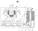
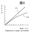
図1は、本発明における被冷却体とその冷却装置を搭載した液晶表示機器を模式的に示した概略構成図である。図2は、従来の液晶表示機器を模式的に示した概略構成図である。図3は、半導体発光素子の印加電流値と相対光度の関係を示す特性図である。図4は、本発明の冷却時における熱変換の状態図である。図5は、冷却装置における受熱部の熱の移動を示した動作図である。 FIG. 1 is a schematic configuration diagram schematically showing a liquid crystal display device equipped with an object to be cooled and its cooling device in the present invention. FIG. 2 is a schematic configuration diagram schematically showing a conventional liquid crystal display device. FIG. 3 is a characteristic diagram showing the relationship between the applied current value of the semiconductor light emitting element and the relative luminous intensity. FIG. 4 is a state diagram of heat conversion during cooling according to the present invention. FIG. 5 is an operation diagram showing the heat transfer of the heat receiving unit in the cooling device.
本発明の液晶表示機器1は、光源から照射される光を変調して画像情報を形成し、形成した画像情報をスクリーン上に投射して拡大表示するものである。この液晶表示機器1は、筐体2内に光学ユニット3を有し、光学ユニット3によって形成された画像情報を投射レンズ4によってスクリーン(図示しない)上に投射する。本発明は、この光学ユニット3を冷却するための冷却装置5を備えている。
The liquid
画像情報を形成する光学ユニット3の機能と構成の概略について、図1によって説明する。 The outline of the function and configuration of the optical unit 3 for forming image information will be described with reference to FIG.
光学ユニット3は、光源から射出された光を光学的な処理によって情報を光学画像に形成するための構成物であり、照明光学系31(R、G、B)、光学変換素子32(R,G,B)、色合成光学系33、等で構成される。 The optical unit 3 is a component for forming information into an optical image by optically processing light emitted from a light source, and includes an illumination optical system 31 (R, G, B), an optical conversion element 32 (R, G, B), a color synthesis optical system 33, and the like.
まず、照明光学系31について説明する。本発明の特徴は、照明光学系31(R、G、B)の光源311(R、G、B)に半導体発光素子を使用していることである。従来の白熱灯光源においては、白色光を赤、緑、青の単色光に分離するためのダイクロイックミラー等の色分離光学系を必要としていたが、単色光の半導体発光素子を光源311(R、G,B)として使用することによって、各光源から直接に光学変換素子32に単色光を投射することになり、色分離光学系を割愛している。
First, the illumination
説明を加えるが、半導体発光素子による光源は、点灯の応答速度が早い、寿命が長い、低消費電力である等の利点が多く上げられることから、液晶表示機器の光源としての期待が大きいものである。 As will be explained, the light source using a semiconductor light emitting element has many advantages such as quick response of lighting, long life, low power consumption, etc. is there.
ただ、この半導体発光素子は、1個の素子の発光する光量として未だ従来の白熱灯に比べ小さいために、複数個の半導体発光素子を束ねて光源としている。白熱灯と同等、あるいはそれ以上の光量を得ようとすると、多くの半導体発光素子をマトリックス状に並べることになる。光源311(R、G、B)として複数個の半導体発光素子を平面的に並べた上で液晶パネルへの平行光として投射するには、当然の如く大きなリフレクタ313(R、G、B)が必要になる。このリフレクタ313(R、G、B)を小型化にするために、集光体312(R、G、B)が設けられている。すなわち、複数個の半導体発光素子を並べた光源311(R、G、B)から照射される光を集光体312(R、G,B)により点光源として集光することにより、小型のリフレクタ313(R、G、B)の反射によって平行光として射出可能とする構成としている。 However, since this semiconductor light-emitting element is still smaller than the conventional incandescent lamp as the amount of light emitted by one element, a plurality of semiconductor light-emitting elements are bundled as a light source. In order to obtain an amount of light equal to or greater than that of an incandescent lamp, many semiconductor light emitting elements are arranged in a matrix. In order to project a plurality of semiconductor light emitting elements as a light source 311 (R, G, B) in a plane and then project as parallel light to a liquid crystal panel, it is natural that a large reflector 313 (R, G, B) is used. I need it. In order to reduce the size of the reflector 313 (R, G, B), a light collector 312 (R, G, B) is provided. That is, a small reflector is formed by condensing light emitted from a light source 311 (R, G, B) in which a plurality of semiconductor light emitting elements are arranged as a point light source by a condenser 312 (R, G, B). 313 (R, G, B) is reflected so that it can be emitted as parallel light.
ここで、集光体312(R、G、B)を割愛するためには、半導体発光素子の個数を減じて点光源に近い状態にすることであり、半導体発光素子の個数を減らすためには、1個あたりの半導体発光素子の光量を上げることなる。現在、半導体発光素子の技術開発は急速であり、大光量の半導体発光素子が開発され始めているが、未だ、光源とするには、数個の半導体発光素子をまとめざるを得ない状況である。 Here, in order to omit the light collector 312 (R, G, B), it is necessary to reduce the number of semiconductor light emitting elements to a state close to a point light source, and to reduce the number of semiconductor light emitting elements. This increases the amount of light emitted from each semiconductor light emitting element. At present, the technological development of semiconductor light emitting devices is rapid, and semiconductor light emitting devices with a large amount of light have begun to be developed. However, in order to make a light source, several semiconductor light emitting devices have to be put together.
一方、半導体発光素子の発光光量は図3に示されるような特性にあるため、半導体発光素子への印加電流を上げることができれば、光量を数倍に増加させることが可能である。ただ、この場合には、半導体発光素子の電流の増加に伴う熱も増加することになる。半導体発光素子における発熱は、白色灯のような高温度ではないが、半導体としての信頼性の問題は、温度上昇に伴って生じることから、半導体発光素子は冷却を十分に考慮する必要がある。 On the other hand, since the amount of light emitted from the semiconductor light emitting element has the characteristics shown in FIG. 3, if the current applied to the semiconductor light emitting element can be increased, the amount of light can be increased several times. However, in this case, the heat accompanying the increase in the current of the semiconductor light emitting element also increases. Although heat generation in the semiconductor light emitting element is not as high as that of a white lamp, the problem of reliability as a semiconductor occurs with an increase in temperature. Therefore, it is necessary to sufficiently consider cooling of the semiconductor light emitting element.
次に、光学変換素子32について説明する。光学変換素子32は、従来同様に集光レンズ321(R、G、B)と、入射側偏光板322(R、G、B)と、射出側偏光板324(R、G、B)と、液晶パネル323(R、G、B)の構成を3組有している。各入射側偏光板322(R、G、B)には、偏光方向が略一方向に揃えられた各色光が入射されるが、光の偏光軸とほぼ同一の方向の偏光光のみを通過させて、その他の光を吸収するものである。各出射側偏光板324(R、G、B)は、液晶パネル323(R、G、B)から射出された光のうち入射側偏光板322(R、G、B)を通過した光の透過軸と直行する偏光軸を有するもののみ透過させて、その他の光を吸収するものである。 Next, the optical conversion element 32 will be described. The optical conversion element 32 includes a condenser lens 321 (R, G, B), an incident side polarizing plate 322 (R, G, B), an exit side polarizing plate 324 (R, G, B), The liquid crystal panel 323 (R, G, B) has three configurations. Each incident-side polarizing plate 322 (R, G, B) receives light of each color whose polarization direction is aligned in substantially one direction, but allows only polarized light in a direction substantially the same as the polarization axis of the light to pass therethrough. It absorbs other light. Each output-side polarizing plate 324 (R, G, B) transmits light that has passed through the incident-side polarizing plate 322 (R, G, B) out of the light emitted from the liquid crystal panel 323 (R, G, B). Only light having a polarization axis perpendicular to the axis is transmitted, and other light is absorbed.
次の色合成光学系33は、各液晶パネル323(R、G、B)によって変調され、各射出側偏光板324(R、G、B)から射出された各色光ごとの画像情報を合成してカラー画像に形成するためのものであり、4つの直角プリズムを張り合わせて構成されている。 The next color synthesizing optical system 33 synthesizes image information for each color light that is modulated by each liquid crystal panel 323 (R, G, B) and emitted from each emission-side polarizing plate 324 (R, G, B). In order to form a color image, four right angle prisms are bonded together.
光通過の最終段である投射レンズ4は、複数のレンズを組合せた構成であり、色合成光学系33で形成されたカラー画像をスクリーン上に拡大投射するものである。 The projection lens 4 which is the final stage of light passage has a configuration in which a plurality of lenses are combined, and enlarges and projects the color image formed by the color synthesis optical system 33 on the screen.
このような液晶表示機器1において、例えば、高輝度の投射画面をえるためには、複数個の各単色半導体発光素子を可能な限り多数個を束ねた光源311(R、G、B)から可能な限りの大きな光量を確保することになり、発生する半導体発光素子の温度上昇を抑制するための冷却装置5を備えることになる。本発明は、光源311(R,G,B)を半導体発光素子としているので、従来の被冷却体であった液晶パネル323(R,G,B)や偏光板322、324(R,G,B)への照射熱を低減できる反面、半導体発光素子の温度上昇を抑制する必要となり、冷却装置5の被冷却体は、半導体発光素子としている。
In such a liquid
さらには、本発明の液晶表示装置1は、外部よりのごみや塵埃の混入を抑制、防止するために筐体2によってほぼ密閉構造としている。
Furthermore, the liquid
この液晶表示機器1の冷却装置5の基本構成について、図1によって説明する。本発明の半導体発光素子を冷却する冷却装置5は、複数の被冷却体に冷却風を強制通流する方式としている。その冷却装置5の構造は、内部に冷媒を通流する配管等で構成した流路と流路内を通流する冷媒への熱伝達を促進ために空気と熱接続するフィンとを有した第1の熱交換器51と、第1の熱交換器51と同様な構造による第2の熱交換器52を有している。第1の熱交換器51と、第2の熱交換器52とは、第1の配管群531によって循環流路を構成するように接続されている。この循環流路の中途には、冷媒を貯留するタンク54と、冷媒を循環駆動するポンプ55が接続されている。
The basic configuration of the
この構成による冷却装置5の冷却の作用について説明する。第1の熱交換器51は、内部を通流する冷媒によって筐体2内の空気の熱を受熱して、低温の冷却風に熱交換する。受熱した冷媒は、冷却装置5の配管531の循環流路によって第2の熱交換器52に移送される。第2の熱交換器52は、冷媒から受熱した熱を放熱する。冷媒はポンプ55により循環駆動され、熱移送を繰り返す。
The cooling effect | action of the
ここで、第1の熱交換器51は、筐体2の内部に設置されており、第2の熱交換器52は、筐体2の外部に設置されている。第1の熱交換器51において熱交換された低温度の空気(冷却風)によって被冷却体を冷却する。冷却風を被冷却体に通風するための送風路56は、筐体2の内部の第1の熱交換器51と被冷却体の半導体発光素子の光源311(R,G,B)とを連接するように設けられている。この送風路56内の冷却風の排出側には噴出し口57を有している。噴出し口57は、被冷却体の配置の状況によって必要に応じて最適な形状等で構成し、配置されている。
Here, the first heat exchanger 51 is installed inside the
さらには、この送風路56及び第1の熱交換器51の下端部には、第1の熱交換器51を通風して低温とされた冷却風により、筐体2内の空気の水分からの液化された水滴を受けるトレイ部561を構成している。このトレイ561とタンク54と直接に接続された第2の配管532を有しており、液化された水滴は、第2の配管532によりタンク54に冷媒とともに貯留される。
Furthermore, at the lower end portion of the
また、第1の熱交換器51に対向して配置され、筐体2の内部の空気を第1の熱交換器51に通風する第1のファン58と、噴出し口57に対向して配置され、冷却風を被冷却体に送風する第2のファン59を有して、筐体内の空気を通風している。ここで、被冷却体の3色光の光源311(R、G、B)は通風される冷却風と熱接続する冷却用のヒートシンク314(R、G、B)を有している。
The first heat exchanger 51 is disposed to face the first heat exchanger 51, and the air inside the
本発明の冷却方法による被冷却体の冷却状態と筐体内空気の熱変換状態を図4により説明する。 The cooling state of the object to be cooled by the cooling method of the present invention and the heat conversion state of the air in the housing will be described with reference to FIG.
液晶表示機器1は、筐体2により密閉された構造としているので、筐体2の内部の空気は、筐体2の外部の空気から遮断されて、外部のごみや塵埃の液晶表示機器1の内部への混入を防止していると共に、所定の温度(Ti)で筐体2の内部で滞留している。
Since the liquid
被冷却体(光源31)は、この筐体2内の空気を第1の熱交換器51で低温(To)の冷却風として形成して噴射されることにより冷却されるため、この被冷却体の冷却された温度(Tc)は、冷却風の空気温度(To)によって得られることになる。また、冷却風の空気温度(To)は、被冷却体の発熱温度(Th)を受熱して、空気温度(Ti)となって、密閉の筐体2内の空気として滞留することになる。すなわち、第1の熱交換器51を通流する冷媒での受熱によって、筐体2内に滞留している空気温度(Ti)を冷却風温度(To)に熱変換している。
The object to be cooled (light source 31) is cooled by forming the air in the
ここで、筐体2内に滞留する空気の温度(Ti)は、他の回路部品などの発熱によって受熱温度(Ti)より高温(Ti+)状態となる場合や、逆に、筐体2の外壁によって自然放熱されるため受熱温度(Ti)より低温(Ti―)状態となる場合等他の要因によって異なることが想定されるが、これらの温度の管理は設計上で考慮することとして、ここでは筐体2内で滞留する空気の温度を被冷却体の冷却温度(Tc)によってのみ関係するものとして考える。
Here, the temperature (Ti) of the air staying in the
筐体2内の空気は、第1のファン58によって第1の熱交換器51に吸引され、フィン等と熱接続した状態で通風された空気の熱は、第1の熱交換器51内の配管流路の内部を通流する冷媒に熱伝達して吸熱される。第1の熱交換器51の冷媒により吸熱された空気は、低温(To)の冷却風となり、送風路56によって導かれ、噴出し口57から対向配置されている光源311(R、G、B)のヒートシンク314(R、G、B)に向けて通風される。光源311(R、G、B)は、この低温(To)の冷却風によって被冷却体の発熱温度(Th)から受熱して冷却温度(Tc)に冷却される。
The air in the
一方、冷却装置5における第1の熱交換器51において筐体2内の空気より受熱した冷媒(温度:To)は、第1の配管群531を循環して第2の熱交換器52まで移送され、第2の熱交換器52において筐体2の外部の温度(Ta)の空気を通風されることによって放熱する。放熱された冷媒(温度:Tr)は、ポンプ55によって再び第1の配管群531内を循環して第1の熱交換器51に移送され、再び筐体2内の空気(温度:Ti)から受熱する。
On the other hand, the refrigerant (temperature: To) that has received heat from the air in the
冷却装置の冷却性能の向上は、被冷却体の発熱温度(Th)を冷媒によっていかに最大の熱量を吸熱して、冷却温度(Tc)に下げるか、かつ外気の温度(Ta)によって冷媒からいかに最大の熱量を放熱して、放熱温度(To)を下げるかによるものである。 The cooling performance of the cooling device can be improved by reducing the heat generation temperature (Th) of the object to be cooled by absorbing the maximum amount of heat by the refrigerant and lowering it to the cooling temperature (Tc), and from the refrigerant by the temperature (Ta) of the outside air. This is because the maximum amount of heat is radiated and the heat radiation temperature (To) is lowered.
低温(To)の冷却風により、発熱体の冷却が熱的なロスなく行われた場合には、発熱体の冷却温度(Tc)は冷却風の温度(To)と同じ温度となり、外気温度(Ta)により放熱が熱的なロス無く行われた場合には、冷媒液の放熱温度(Tr)は外気温度(Ta)と同じ温度となる。 When the heating element is cooled without thermal loss by the low-temperature (To) cooling air, the cooling temperature (Tc) of the heating element becomes the same as the temperature (To) of the cooling air, and the outside air temperature ( When heat radiation is performed without thermal loss according to Ta), the heat radiation temperature (Tr) of the refrigerant liquid is the same as the outside air temperature (Ta).
また、この熱交換の動作において、第1の熱交換器51における受熱量と第2の熱交換器52における放熱量が等しいことになる。ただ、実際においては、冷却風温度(To)により冷却された被冷却体の発熱温度(Th)は冷却風温度(To)より高い冷却温度(Tc)までしか下がらない場合がある。これは第1の熱交換51、及び第2の熱交換器52における熱伝達効率や、冷却風による熱伝達効率等によるものであるが、この状態においても冷却装置5における受熱量と放熱量は同量となることは当然である。
In this heat exchange operation, the amount of heat received by the first heat exchanger 51 is equal to the amount of heat released by the
そこで、本発明の冷却方式に関しての冷却性能について説明する。 The cooling performance related to the cooling system of the present invention will be described.
本発明の冷却方式と従来の液冷方式は、第1の熱交換器51の構造が異なるものの、この異なった第1の熱交換器において冷媒液で受熱した熱量を第2の熱交換器52(放熱部材)で放熱する構造は同じものである。このことから、本発明の第1の熱交換器51によって受熱され低温となされた空気温度(To)すなわち、冷媒液受熱温度(To)によって冷却される被冷却体の冷却状態について、従来の水冷方式の受熱ジャケットにおける受熱状態と比較すればよい。
Although the cooling system of the present invention and the conventional liquid cooling system are different in the structure of the first heat exchanger 51, the amount of heat received by the refrigerant liquid in the different first heat exchanger is converted into the
第1の熱交換器51における受熱量について図5によって説明する。図5は、冷却方式における第1の熱交換器の構造による温度の移動状態を説明したものである。図5(a)は、従来の液冷方式における熱交換器(受熱ジャケット)の温度移動の状態を参考として模式的に示したものであり、図5(b)は、本発明の冷却方式における第1の熱交換器の温度移動の状態を模式的に示している。両者を比較しながら説明する。本発明の第1の熱交換器51と従来の受熱ジャケットとともに高温部から熱を吸熱して低温部とする受熱部の構造であり、この受熱部の熱交換器における熱の移動について順を追って記す。以下の括弧内で付記した構成部品は、前者が図5(a)に関するものであり、後者が図5(b)に関するものである。 The amount of heat received in the first heat exchanger 51 will be described with reference to FIG. FIG. 5 illustrates the temperature shift state by the structure of the first heat exchanger in the cooling system. FIG. 5 (a) schematically shows a state of temperature movement of a heat exchanger (heat receiving jacket) in a conventional liquid cooling system as a reference, and FIG. 5 (b) shows the cooling system of the present invention. The state of the temperature shift of the 1st heat exchanger is shown typically. A description will be given while comparing the two. It is the structure of the heat receiving part which absorbs heat from the high temperature part together with the first heat exchanger 51 of the present invention and the conventional heat receiving jacket to make the low temperature part, and the heat transfer in the heat exchanger of this heat receiving part is followed in order. I write. In the following components shown in parentheses, the former relates to FIG. 5 (a) and the latter relates to FIG. 5 (b).
(1)高温部(発熱体/高温空気)は、熱交換器を構成する部材(受熱ジャケットと流路/フィンと流路)において、まず、熱伝達(グリース部伝達/空気強制対流伝達)される。 (1) The high temperature part (heating element / high temperature air) is first subjected to heat transfer (grease transfer / air forced convection transfer) in the members (heat receiving jacket and flow path / fin and flow path) constituting the heat exchanger. The
(2)「つづいて、熱交換器を構成する部材(受熱ジャケットと流路/フィンと流路)の材質内を熱伝導される。 (2) “Continuing, heat conduction is performed in the material of the members (heat receiving jacket, flow path / fin and flow path) constituting the heat exchanger.
(3)さらに、熱交換器を構成する部材(受熱ジャケットと流路/フィンと流路)から冷媒液に熱伝達される。 (3) Furthermore, heat is transferred from the members (heat receiving jacket, flow path / fin and flow path) constituting the heat exchanger to the refrigerant liquid.
(4)冷媒液内で熱伝導される。 (4) Conducted in the refrigerant liquid.
ここで、(2)の熱伝導、(3)の熱伝達、(4)の熱伝導による熱の移動は、本発明の冷却方式(b)と従来の液冷方式(a)とで使用される構成部材の材質、や駆動される冷媒液の流速等の条件を同じと仮定すると、この(2)、(3)、(4)の部分の熱交換性能は同じとなると想定できる。仮に、(a)、(b)の方式で熱交換性能が大きく異なる現象が発生するならば、その要因は、(1)の熱伝達(熱伝達率)の部分による相違といえる。 Here, the heat transfer of (2), the heat transfer of (3), and the heat transfer by the heat transfer of (4) are used in the cooling method (b) of the present invention and the conventional liquid cooling method (a). Assuming that the conditions such as the material of the constituent members and the flow rate of the driven refrigerant liquid are the same, it can be assumed that the heat exchange performance of the parts (2), (3), and (4) is the same. If a phenomenon in which the heat exchange performance is greatly different between the methods (a) and (b) occurs, it can be said that the cause is a difference due to the heat transfer (heat transfer coefficient) part of (1).
この(1)の熱伝達率は、W/(m2・K)の単位で表わされる値であり、
物体間の熱の移動能力を示すものである。物性によって定まる値ではなく、物質間の相対流速、圧力、表面形状などによって変化するものである。
The heat transfer coefficient of (1) is a value expressed in units of W / (m 2 · K),
It shows the ability to transfer heat between objects. It is not a value determined by physical properties, but changes depending on the relative flow velocity between materials, pressure, surface shape, and the like.
一般的な空気強制対流の熱伝達率は、20〜250W/m2・Kであり、グリース部による熱伝達率1000W/m2・Kと考えると、第1の熱交換器51のフィン形状面積を従来に受熱部面積に50倍に近い状況を確保することによって、同レベルの熱伝達量を確保できることを示している。 The heat transfer coefficient of general air forced convection is 20 to 250 W / m 2 · K, and assuming that the heat transfer rate by the grease part is 1000 W / m 2 · K, the fin shape area of the first heat exchanger 51 It is shown that a heat transfer amount of the same level can be ensured by securing a situation close to 50 times the area of the heat receiving part.
本発明においては、第1のファン58により送風される空気の流速と、第1の熱交換器51に設けられたフィンの面積によって設定される熱伝達率を従来の液冷方式のグリ−スの熱伝達率に約等しくなるように設定して冷却性能を得ている。
In the present invention, the heat transfer coefficient set by the flow rate of the air blown by the
この強制冷却風による冷却方式において十分な冷却性能を得ることができることが確認されることから、密閉された液晶表示装置1の内部の半導体発光素子の光源311の冷却だけでなく、光等の透過によって冷却の困難さを有する液晶パネルなどの被冷却体の冷却も容易に対応できる。このことは、被冷却体を特定の発熱体に限定されずに冷却できるとともに、外部のごみや塵埃の対策を必要とする電子機器においても使用できるものである。
Since it is confirmed that sufficient cooling performance can be obtained in this cooling method using forced cooling air, not only cooling of the light source 311 of the semiconductor light emitting element inside the sealed liquid
加えるに、第1の熱交換器51の近傍においては、高温(Ti)の空気を通風して、第1の熱交換器51により吸熱され、低温(To)の空気となることから、空気中の水分が冷却の過程で水滴となって生じる場合が想定される。仮に、水滴となった水分は送風路56の下端部に設けられたトレイ部に接続された第2の配管532によってタンク54に流れ込む構成として、液晶表示機器内の水滴によるトラブルを回避する構成としている。
In addition, in the vicinity of the first heat exchanger 51, high-temperature (Ti) air is ventilated and absorbed by the first heat exchanger 51 to become low-temperature (To) air. It is assumed that the water content is formed as water droplets during the cooling process. Assuming that the water that has become water droplets flows into the
1 液晶表示機器、2 筐体、3 光学ユニット、31 照明光学系、 311 光源、 314 ヒートシンク、32 光学変換素子、 321 集光レンズ、 322 入射側偏光板、 323 液晶パネル、 324 射出側偏光板、33 色合成光学系4 投射レンズ5 冷却装置、 51 第1の熱交換器、 52 第2の熱交換器56 送風路、 57 噴出し口。
DESCRIPTION OF
Claims (3)
該複数の単色光の光源から各々の光を照射される複数のライトバルブと、
該複数のライトバルブによって形成される情報を合成し、投射する光学部材とを備え、
略密閉した筐体で構成される液晶表示機器において、
前記複数の各々の光源は、光を照射する背面側にヒートシンクを一体的に有する構成とし、
該ヒートシンクを介して光源を冷却する冷却装置は、冷媒を通流する配管を備え、前記表示機器の筐体の内部に載置される第1の熱交換器と、冷媒を通流する配管を備え、前記表示機器の筐体の外部に設置される第2の熱交換器との間で冷媒を循環し、前記第1の熱交換器において冷媒により受熱し、前記第2の熱交換器によって冷媒から放熱する構成となし、
前記密閉された筐体の内部の空気を前記第1の熱交換器に通風して、前記第1の熱交換器によって前記筐体の内部の空気を低温風となして、前記第1の熱交換器から送出した前記低温風を前記複数の光源のヒートシンクに通風して該複数の光源を冷却する構成としたことを特徴とする液晶表示機器。 A plurality of monochromatic light sources by semiconductor light emitting elements;
A plurality of light valves irradiated with each light from the plurality of monochromatic light sources;
An optical member that synthesizes and projects information formed by the plurality of light valves,
In a liquid crystal display device composed of a substantially sealed casing,
Each of the plurality of light sources is configured to have a heat sink integrally on the back side that emits light,
The cooling device for cooling the light source via the heat sink includes a pipe through which the refrigerant flows, and includes a first heat exchanger placed inside the casing of the display device and a pipe through which the refrigerant flows. A refrigerant is circulated with a second heat exchanger installed outside the housing of the display device, and the first heat exchanger receives heat with the refrigerant, and the second heat exchanger No configuration to dissipate heat from the refrigerant,
The air inside the sealed casing is passed through the first heat exchanger, and the air inside the casing is converted into low-temperature air by the first heat exchanger, so that the first heat A liquid crystal display device, wherein the low temperature air sent from the exchanger is passed through heat sinks of the plurality of light sources to cool the plurality of light sources.
前記第1の熱交換器に通風された空気を前記光源のヒートシンクに送風する送風路を前記第1の熱交換器に隣接して備えて、前記低温風を前記送風路の噴出し口より前記複数の光源のヒートシンクに通風する構成としたことを特徴とする液晶表示機器。 The liquid crystal display device according to claim 1,
An air passage for blowing the air ventilated through the first heat exchanger to the heat sink of the light source is provided adjacent to the first heat exchanger, and the low temperature air is supplied from an outlet of the air passage. A liquid crystal display device characterized by being configured to ventilate heat sinks of a plurality of light sources.
前記冷却装置を、前記第1の熱交換器と、前記第2の熱交換器と、タンクと、ポンプとを第1の配管群によって接続して冷媒を循環する構成とし、前記第1の熱交換器および通風路に対面して通風路の下端に設けられたトレイ部を有し、該下端に設けたトレイ部と前記タンクとを第2の配管により直接接続したことを特徴とする液晶表示機器。
In the liquid crystal display device according to claim 1 and claim 2,
The cooling device has a configuration in which the first heat exchanger, the second heat exchanger, a tank, and a pump are connected by a first pipe group to circulate a refrigerant, and the first heat exchanger A liquid crystal display comprising a tray portion provided at a lower end of the ventilation path facing the exchanger and the ventilation path, and the tray portion provided at the lower end and the tank are directly connected by a second pipe. machine.
Priority Applications (1)
| Application Number | Priority Date | Filing Date | Title |
|---|---|---|---|
| JP2006224829A JP4811190B2 (en) | 2006-08-22 | 2006-08-22 | LCD display |
Applications Claiming Priority (1)
| Application Number | Priority Date | Filing Date | Title |
|---|---|---|---|
| JP2006224829A JP4811190B2 (en) | 2006-08-22 | 2006-08-22 | LCD display |
Publications (2)
| Publication Number | Publication Date |
|---|---|
| JP2008051831A JP2008051831A (en) | 2008-03-06 |
| JP4811190B2 true JP4811190B2 (en) | 2011-11-09 |
Family
ID=39235981
Family Applications (1)
| Application Number | Title | Priority Date | Filing Date |
|---|---|---|---|
| JP2006224829A Expired - Fee Related JP4811190B2 (en) | 2006-08-22 | 2006-08-22 | LCD display |
Country Status (1)
| Country | Link |
|---|---|
| JP (1) | JP4811190B2 (en) |
Families Citing this family (7)
| Publication number | Priority date | Publication date | Assignee | Title |
|---|---|---|---|---|
| JP2010230725A (en) * | 2009-03-25 | 2010-10-14 | Seiko Epson Corp | Projector |
| JP4831202B2 (en) * | 2009-04-03 | 2011-12-07 | セイコーエプソン株式会社 | projector |
| JP6900173B2 (en) * | 2016-11-25 | 2021-07-07 | キヤノン株式会社 | Lighting device and image display device using it |
| JP7031373B2 (en) * | 2018-03-01 | 2022-03-08 | セイコーエプソン株式会社 | projector |
| WO2020059397A1 (en) * | 2018-09-20 | 2020-03-26 | 富士フイルム株式会社 | Projecting device and method for controlling same |
| CN112823310A (en) * | 2018-09-25 | 2021-05-18 | 堺显示器制品株式会社 | Liquid crystal display device having a plurality of pixel electrodes |
| JP2022035242A (en) * | 2020-08-20 | 2022-03-04 | パナソニックIpマネジメント株式会社 | Cooling device and projection-type image display device including the same |
Family Cites Families (6)
| Publication number | Priority date | Publication date | Assignee | Title |
|---|---|---|---|---|
| JPH06189240A (en) * | 1992-12-18 | 1994-07-08 | Fujitsu General Ltd | Liquid crystal type projector |
| JP2005121250A (en) * | 2003-10-14 | 2005-05-12 | Seiko Epson Corp | Cooling device, and rear projector |
| JP2005121890A (en) * | 2003-10-16 | 2005-05-12 | Seiko Epson Corp | Image display device, and method for controlling temperature of light source |
| JP4096896B2 (en) * | 2004-03-10 | 2008-06-04 | セイコーエプソン株式会社 | projector |
| JP2006047718A (en) * | 2004-08-05 | 2006-02-16 | Seiko Epson Corp | Projector |
| JP4657022B2 (en) * | 2004-10-15 | 2011-03-23 | 三洋電機株式会社 | Projection display device |
-
2006
- 2006-08-22 JP JP2006224829A patent/JP4811190B2/en not_active Expired - Fee Related
Also Published As
| Publication number | Publication date |
|---|---|
| JP2008051831A (en) | 2008-03-06 |
Similar Documents
| Publication | Publication Date | Title |
|---|---|---|
| JP5023711B2 (en) | Cooling system | |
| US7993009B2 (en) | Projector | |
| US7556383B2 (en) | Projection display apparatus using liquid cooling and air cooling | |
| JP5085888B2 (en) | Cooling device for electronic equipment | |
| JP4559361B2 (en) | Projection display | |
| JP4172503B2 (en) | Cooling device and projector | |
| JP4811190B2 (en) | LCD display | |
| US8093547B2 (en) | Projector and light source apparatus having a second reflector for reflecting light in infrared region | |
| KR20060097937A (en) | Cooling apparatus and projector having the same | |
| JP5205064B2 (en) | Projection display device | |
| JP4657242B2 (en) | Projection display device | |
| JP4572158B2 (en) | Projection display | |
| JP4957019B2 (en) | projector | |
| JP2010197500A (en) | Light-emitting device, light source device, and projector using the light source device | |
| JP2009222869A (en) | Projector | |
| JP2004038105A (en) | Liquid crystal projector and projection block | |
| TW200909989A (en) | Projection device and heat dissipation method | |
| JP2009258670A (en) | Projector | |
| JPWO2018042816A1 (en) | Image projection device | |
| KR20140121525A (en) | Display apparatus | |
| JP4860663B2 (en) | Liquid crystal unit cooling method | |
| JP2020052367A (en) | Projection type display device | |
| JP7371672B2 (en) | projector | |
| JP5150181B2 (en) | Projector cooling system | |
| JP2024054504A (en) | projector |
Legal Events
| Date | Code | Title | Description |
|---|---|---|---|
| A621 | Written request for application examination |
Free format text: JAPANESE INTERMEDIATE CODE: A621 Effective date: 20090310 |
|
| A977 | Report on retrieval |
Free format text: JAPANESE INTERMEDIATE CODE: A971007 Effective date: 20110713 |
|
| TRDD | Decision of grant or rejection written | ||
| A01 | Written decision to grant a patent or to grant a registration (utility model) |
Free format text: JAPANESE INTERMEDIATE CODE: A01 Effective date: 20110726 |
|
| A01 | Written decision to grant a patent or to grant a registration (utility model) |
Free format text: JAPANESE INTERMEDIATE CODE: A01 |
|
| A61 | First payment of annual fees (during grant procedure) |
Free format text: JAPANESE INTERMEDIATE CODE: A61 Effective date: 20110808 |
|
| R151 | Written notification of patent or utility model registration |
Ref document number: 4811190 Country of ref document: JP Free format text: JAPANESE INTERMEDIATE CODE: R151 |
|
| FPAY | Renewal fee payment (event date is renewal date of database) |
Free format text: PAYMENT UNTIL: 20140902 Year of fee payment: 3 |
|
| S111 | Request for change of ownership or part of ownership |
Free format text: JAPANESE INTERMEDIATE CODE: R313111 |
|
| R350 | Written notification of registration of transfer |
Free format text: JAPANESE INTERMEDIATE CODE: R350 |
|
| S111 | Request for change of ownership or part of ownership |
Free format text: JAPANESE INTERMEDIATE CODE: R313111 |
|
| R350 | Written notification of registration of transfer |
Free format text: JAPANESE INTERMEDIATE CODE: R350 |
|
| R250 | Receipt of annual fees |
Free format text: JAPANESE INTERMEDIATE CODE: R250 |
|
| R250 | Receipt of annual fees |
Free format text: JAPANESE INTERMEDIATE CODE: R250 |
|
| R250 | Receipt of annual fees |
Free format text: JAPANESE INTERMEDIATE CODE: R250 |
|
| LAPS | Cancellation because of no payment of annual fees |