本発明に係る原稿圧着板開閉装置を用いた例えば複合機のようなOA機器の原稿圧着板を開いて見た斜視図である。It is the perspective view which opened and looked at the original pressure plate of OA equipment like a multifunction machine using the original pressure plate open / close device according to the present invention.
本発明に係る原稿圧着板開閉装置の側面図である。FIG. 3 is a side view of the document crimping plate opening / closing device according to the present invention.
図2に示した原稿圧着板開閉装置の平面図である。FIG. 3 is a plan view of the document crimping plate opening / closing device shown in FIG. 2.
図2に示した原稿圧着板開閉装置の背面図である。FIG. 3 is a rear view of the document crimping plate opening / closing device shown in FIG. 2.
図3に示した原稿圧着板開閉装置の内部構造を説明するための側断面図である。FIG. 4 is a side sectional view for explaining an internal structure of the document crimping plate opening / closing device shown in FIG. 3.
図3に示した原稿圧着板開閉装置の動作を説明するための側断面図である。FIG. 4 is a side sectional view for explaining the operation of the document crimping plate opening / closing device shown in FIG. 3.
図3に示した原稿圧着板開閉装置の動作を説明するための側断面図である。FIG. 4 is a side sectional view for explaining the operation of the document crimping plate opening / closing device shown in FIG. 3.
図2乃至図4に示した原稿圧着板開閉装置の取付部材を示し、(a)はその側面図、(b)はその平面図、(c)はその背面図である。FIGS. 2 to 4 show attachment members of the document crimping plate opening / closing device, wherein FIG. 2A is a side view thereof, FIG. 2B is a plan view thereof, and FIG.
図2乃至図4に示した原稿圧着板開閉装置の支持部材の底面図である。FIG. 5 is a bottom view of a support member of the document crimping plate opening / closing device shown in FIGS. 2 to 4.
図2乃至図4に示した原稿圧着板開閉装置ストッパー部材を示し、(a)はその側面図、(b)はその側断面図、(c)はその正面図である。FIGS. 2 to 4 show the stopper member of the original pressure plate opening / closing device shown in FIGS. 2 to 4, in which (a) is a side view thereof, (b) is a side sectional view thereof , and (c) is a front view thereof .
図2乃至図4に示した原稿圧着板開閉装置のストッパー部材の他の実施例を示す側断面図である。FIG. 5 is a side sectional view showing another embodiment of a stopper member of the document crimping plate opening / closing device shown in FIGS. 2 to 4.
本発明に係る原稿圧着板開閉装置の指挟み防止手段の他の実施例を示し、(a)はその側断面図、(b)はその背面図である。The other example of the finger pinching prevention means of the document pressing plate opening and closing apparatus according to the present invention is shown, (a) is a side sectional view thereof, and (b) is a rear view thereof.
本発明に係る原稿圧着板開閉装置の指挟み防止手段の他の実施例を示し、(a)はその平面図、(b)はその背面図である。The other example of the pinch prevention means of the document crimping plate opening and closing apparatus according to the present invention is shown, (a) is a plan view thereof, and (b) is a rear view thereof.
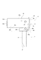
図2乃至図7は、本発明の実施例1に係る原稿圧着板開閉装置Bの一例を具体的に示す図である。本発明に係る原稿圧着板開閉装置Bは、装置本体a側へ取り付けられる取付部材1と、この取付部材1の両側板1b、1bへその両側板2b、2bをヒンジピン3を介して回転可能に連結した支持部材2と、この支持部材2の両側板2b、2bの自由端側へ連結ピン4を介して該支持部材2とは異なる方向へ回転可能となるように軸着したところの、原稿圧着板Cを取り付けるリフト部材6と、取付部材1の両側板1b、1b間に設けた受圧部材5と、この受圧部材5にカム部10aを当接させて前記支持部材2内部に抱持板2c、2cに抱えられて摺動可能に収装されたカムスライダー10と、リフト部材6の両側板6b、6b間に設けた作動部材9と、この作動部材9に当接させて支持部材2内部に摺動可能に収装されたスプリング受部材11と、カムスライダー10とスプリング受部材11との間に弾設させることにより、前記リフト部材6を支持部材2と重なり合う方向へ回転付勢させつつ、支持部材2を少なくとも原稿圧着板Cの開成方向へ付勢させる弾性手段12と、取付部材1と支持部材2及び又はリフト部材6との間に設けた指挟み防止手段13と、で構成したものである。
FIGS. 2 to 7 are diagrams specifically showing an example of the document pressing plate opening / closing device B according to the first embodiment of the present invention. The document crimping plate opening / closing apparatus B according to the present invention is capable of rotating the attachment member 1 attached to the apparatus main body a side, and both side plates 1b, 1b of the attachment member 1 via the hinge pins 3 to both side plates 2b, 2b. A document, which is pivotally attached to the connected support member 2 and the free ends of both side plates 2b, 2b of the support member 2 via a connection pin 4 so as to be rotatable in a direction different from that of the support member 2. A lift member 6 for attaching the crimping plate C, a pressure receiving member 5 provided between both side plates 1b and 1b of the attachment member 1, and a cam portion 10a abutting against the pressure receiving member 5 to hold the holding plate inside the support member 2 2c, 2c, a cam slider 10 that is slidably housed, an operating member 9 provided between both side plates 6b, 6b of the lift member 6, and a supporting member 2 in contact with the operating member 9 Spring receiving part slidably housed inside 11, and between the cam slider 10 and the spring receiving member 11, the support member 2 is at least opened to the original pressure plate C while the lift member 6 is rotationally biased in a direction overlapping the support member 2. It comprises elastic means 12 for biasing in the direction, and finger pinching prevention means 13 provided between the attachment member 1 and the support member 2 or the lift member 6.
さらに詳しくは、取付部材1は、とくに図8に示したように、装置本体a上に取り付けられる取付ベース1aと、この取付ベース1aの両側端部からそれぞれ当該取付ベース1aに対して直交する上方向(略直交する方向も含む)に折り曲げた両側板1b、1bと、取付ベース1aの一端部(後端部)から該取付ベース1aに対して直交する上方向(略直交する方向も含む)に折り曲げて、その両側部の一部を取付部材1の両側板1b、1bに係止させた略矩形状の後板1cと、から構成されている。その他、指示記号1d、1dのものはヒンジピン取付孔であり、指示記号1e、1eのものは受圧部材取付孔であり、さらに指示記号1f、1fのものは図示してない係止ピンの係止孔である。さらに、指示記号1g、1gは係止片であり、指示記号1h、1h(一方のみ表示)は、係止片1g、1gを係止させる係止孔であり、さらに指示記号1i、1kは取付孔である。
More specifically, as shown in FIG. 8, the mounting member 1 includes a mounting base 1a mounted on the apparatus main body a and upper portions orthogonal to the mounting base 1a from both side ends of the mounting base 1a. Both side plates 1b and 1b bent in a direction (including a substantially orthogonal direction) and an upward direction (including a substantially orthogonal direction) perpendicular to the mounting base 1a from one end (rear end) of the mounting base 1a And a substantially rectangular rear plate 1c in which a part of both side portions thereof is engaged with both side plates 1b and 1b of the mounting member 1. In addition, the designation symbols 1d and 1d are hinge pin mounting holes, the designation symbols 1e and 1e are pressure receiving member mounting holes, and the designation symbols 1f and 1f are latching locking pins (not shown). It is a hole. Furthermore, instruction symbol 1 g, 1 g is engaging piece, instruction symbols 1h, 1h (display only one) is Ri engaging hole der for locking the locking piece 1 g, 1 g, further indication symbol 1i, 1k is It is a mounting hole .
支持部材2は、とくに図9にも示したように、背板2aと、この背板2aの両端部から下方へ折り曲げられた両側板2b、2bと、この両側板2b、2bの下端側からは共に内側へ曲げられた抱持板2c、2cから構成されており、両側板2b、2bは上述したように、ヒンジピン3によって取付部材1の両側板1b、1bへ回転可能に連結されている。両側板2b、2bの自由端側には、連結ピン4を介してリフト部材6が回転可能に軸着されると共に、作動部材9の両端側が入り込むガイド溝部2d、2dが設けられている。さらに、背板2aの後部は後方へ伸張され後述する指挟み防止手段13を構成する伸張部2eが設けられ、この伸張部2eの両端部側には、これも後述する指挟み防止手段13を構成する溝部2f、2fが設けられている。その他、指示記号2h、2hは係止孔、指示記号2i、2iは組立時に用いるストッパー孔である。
The support member 2, especially as shown in FIG. 9, the back plate 2a, side plates 2b from both ends bent downwardly of the back plate 2a, and 2b, the side plates 2b, the lower end side of the 2b Are composed of holding plates 2c and 2c bent inward, and the side plates 2b and 2b are rotatably connected to the side plates 1b and 1b of the mounting member 1 by the hinge pins 3 as described above. . On the free ends of the side plates 2b and 2b, there are provided guide groove portions 2d and 2d into which the lift member 6 is rotatably mounted via the connecting pin 4 and into which both end sides of the operating member 9 enter. Further, the rear portion of the back plate 2a is extended rearward to be provided with extension portions 2e that constitute finger pinching prevention means 13 described later, and the finger pinching prevention means 13 that will also be described later is provided on both ends of the extension portion 2e. Groove portions 2f and 2f are provided. In addition, the indication symbols 2h and 2h are locking holes, and the indication symbols 2i and 2i are stopper holes used during assembly.
カムスライダー10とスプリング受部材11の間に、互いの両端部側を当該カムスライダー10とスプリング受部材11の互いの開口部内に挿入させて、大径コイルスプリングから成る弾性手段12が弾設されており、これにより、カム部10aは受圧部材5と圧接し、当接部11aは作動部材9と圧接状態にある。この弾性手段12を構成するコイルスプリングは、1個でも2個以上でもよく、さらには大径のコイルスプリングの中に小径のコイルスプリングを入れて互いに重合させて用いても良い。実施例のものは、大径のコイルスプリングを1個用いてカムスライダー10とスプリング受部材11をそれぞれ互いに離間する方向に付勢させている。
Between cam slider 10 and the spring receiving member 11, by inserting the both end portions of each other to the cam slider 10 and the mutual opening of the spring receiving member 11, the elastic means 12 consisting et al or the large-diameter coil scan purine grayed bullet Thus, the cam portion 10 a is in pressure contact with the pressure receiving member 5, and the contact portion 11 a is in pressure contact with the operating member 9. The elastic means 12 may be composed of one coil spring or two or more coil springs. Furthermore, a small-diameter coil spring may be placed in a large-diameter coil spring and overlapped with each other. Those examples are respectively is biased in a direction away from each other the cam slider 10 and the spring receiving member 11 by using one coil spring having a large diameter.
この閉成状態においては、伸張部2eや6dが後方に伸びて取付部材1やストッパー部材8の上端部側を覆い、さらに突起部8e、8eが間隙の外方向を塞ぐので、取付部材1の部分に手を当てた状態のときに原稿圧着板Cが不意に開いても、取付部材1やストッパー部材8と支持部材2やリフト部材6の後端部との間で指を挟んでしまうことを防止できるものである。尚、図10の(c)において指示記号8f、8f・・・は取付孔である。
In this closed state, the extension portions 2e and 6d extend rearward to cover the upper end side of the attachment member 1 and the stopper member 8, and the protrusions 8e and 8e block the outward direction of the gap. Even if the document pressing plate C opens unexpectedly when a hand is placed on the part, a finger may be caught between the mounting member 1 or the stopper member 8 and the rear end portion of the support member 2 or the lift member 6. Can be prevented. In FIG. 10C, reference symbols 8f, 8f,... Are mounting holes.
図11は、本発明に係る原稿圧着板開閉装置のさらに他の実施例を示す。この実施例2に係る原稿圧着板開閉装置Eは、リフト部材がない点で、実施例1のものと異なっている。即ち、取付部材20には、取付ベース20aと、両側板20b、20b(一方のみ表示)と、後板20cを有し、取付ベース20aに取付脚部21が設けられており、この取付脚部21は装置本体aに設けた取付挿入孔a’に挿脱自在に挿入されて装置本体aへ取り付けられている。支持部材22は、背板22aと、この背板22aの両側から下方へ折り曲げて形成させた両側板22b、22bと、この両側板22b、22bの下端部側から内側へ折り曲げて形成させた抱持板22c、22c(一方のみ表示)と、背板22aの一端部から下方へ折り曲げて形成させた頂板22dと、この頂板22dを支えるべく両側板22bの先端からそれぞれ内側へ折り曲げた押さえ板部22e、22e(一方のみ表示)とから構成され、ヒンジピン23を介して取付部材20に対して回動可能に連結されている。さらに、指示記号8のものは取付部材20の後板20cに取り付けたストッパー部材であり、指示記号8e、8eで示したものはストッパー部材8の側板8c、8cの上端部に設けた突起部である。このストッパー部材8の構成は実施例1のものと同じである。
FIG. 11 shows still another embodiment of the document crimping plate opening / closing device according to the present invention. The document crimping plate opening / closing device E according to the second embodiment is different from that of the first embodiment in that there is no lift member. That is, the mounting member 20 includes a mounting base 20a, both side plates 20b and 20b (only one is shown), and a rear plate 20c. The mounting base 20a is provided with a mounting leg 21. 21 is attached to the apparatus main body a by being removably inserted into an attachment insertion hole a ′ provided in the apparatus main body a. The support member 22 includes a back plate 22a, both side plates 22b and 22b formed by bending downward from both sides of the back plate 22a, and a side plate formed by bending inward from the lower end side of both side plates 22b and 22b. Holding plates 22c and 22c (only one is shown), a top plate 22d formed by bending downward from one end portion of the back plate 22a, and a holding plate portion bent inward from the ends of both side plates 22b to support the top plate 22d. 22e and 22e (only one is displayed), and is connected to the attachment member 20 via the hinge pin 23 so as to be rotatable. Further, the reference symbol 8 is a stopper member attached to the rear plate 20c of the attachment member 20, and the indication symbols 8e and 8e are protrusions provided on the upper ends of the side plates 8c and 8c of the stopper member 8. is there. The configuration of the stopper member 8 is the same as that of the first embodiment.